Embed Size (px)
Citation preview
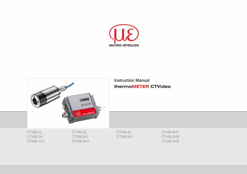
Instruction ManualthermoMETER CTVideo
CTVM-1L CTVM-1H CTVM-1H1
CTVM-2L CTVM-2H CTVM-2H1
CTVM-3L CTVM-3H
CTVM-3H1 CTVM-3H2 CTVM-3H3
MICRO-EPSILONMESSTECHNIKGmbH & Co. KGKönigbacher Strasse 15
94496 Ortenburg / Germany
Tel. +49 (0) 8542 / 168-0 Fax +49 (0) 8542 / [email protected]
Certified acc. to DIN EN ISO 9001: 2008
Infrared sensor
thermoMETER CTVideo
Contents
1. Safety ........................................................................................................................................ 71.1 Symbols Used ................................................................................................................................................. 71.2 Warnings .......................................................................................................................................................... 71.3 Notes on CE Identification ............................................................................................................................... 91.4 Proper Use ..................................................................................................................................................... 101.5 Proper Environment ....................................................................................................................................... 10
2. Technical Data ........................................................................................................................ 112.1 Functional Principle ....................................................................................................................................... 112.2 Sensor Models ............................................................................................................................................... 122.3 General Specification .................................................................................................................................... 132.4 Electrical Specification .................................................................................................................................. 142.5 Measurement Specification ........................................................................................................................... 15
2.5.1 CTVM-1 Models ............................................................................................................................ 152.5.2 CTVM-2 Models ........................................................................................................................... 162.5.3 CTVM-3 Models ........................................................................................................................... 17
3. Delivery ................................................................................................................................... 183.1 Unpacking ...................................................................................................................................................... 183.2 Storage .......................................................................................................................................................... 18
4. Optics ...................................................................................................................................... 19
5. Mechanical Installation .......................................................................................................... 21
6. Electrical Installation .............................................................................................................. 246.1 Cable Connections ........................................................................................................................................ 24
6.1.1 Standard Version .......................................................................................................................... 246.1.2 High Temperature Version ............................................................................................................ 24
6.2 Pin Assignment .............................................................................................................................................. 266.3 Power Supply ................................................................................................................................................. 276.4 Cable Mounting ............................................................................................................................................. 286.5 Ground Connection ....................................................................................................................................... 29
thermoMETER CTVideo
7. Sensor Calibration Code ....................................................................................................... 30
8. Outputs and Inputs ................................................................................................................. 318.1 Analog Output ................................................................................................................................................ 318.2 Digital Interface .............................................................................................................................................. 318.3 Functional Inputs ........................................................................................................................................... 328.4 Alarms ............................................................................................................................................................ 32
8.4.1 Output Channel 1 ......................................................................................................................... 328.4.2 Visual Alarms ................................................................................................................................ 33
9. Operation ................................................................................................................................ 349.1 Restoring Factory Setting .............................................................................................................................. 349.2 Sensor Setup ................................................................................................................................................. 369.3 Explanation to the Menu Items ...................................................................................................................... 379.4 Visor Options ................................................................................................................................................. 409.5 Focusing and Video Sighting ........................................................................................................................ 419.6 Error Messages .............................................................................................................................................. 42
10. Instructions for Operation...................................................................................................... 4210.1 Cleaning ......................................................................................................................................................... 42
11. Software .................................................................................................................................. 4311.1 Installation ...................................................................................................................................................... 4311.2 System Requirements ................................................................................................................................... 4311.3 Main Features ................................................................................................................................................ 43
12. Communication Settings ........................................................................................................ 4412.1 Serial Interface ............................................................................................................................................... 4412.2 Protocol .......................................................................................................................................................... 4412.3 ASCII Protocol ............................................................................................................................................... 4412.4 Saving of Parameter Settings ........................................................................................................................ 4512.5 Basics of Infrared Thermometry .................................................................................................................... 46
13. Emissivity ................................................................................................................................ 4713.1 Definition ........................................................................................................................................................ 4713.2 Determination of Unknown Emissivity ........................................................................................................... 4713.3 Characteristic Emissivities ............................................................................................................................. 48
thermoMETER CTVideo
14. Warranty ................................................................................................................................. 49
15. Service, Repair ....................................................................................................................... 50
16. Decommissioning, Disposal .................................................................................................. 50
Appendix
A 1 Accessories ............................................................................................................................ 51A 1.1 Air Purge Collar .............................................................................................................................................. 51A 1.2 Mounting Bracket .......................................................................................................................................... 52A 1.3 Water Cooled Housing .................................................................................................................................. 53A 1.4 High Temperature Cable ................................................................................................................................ 53A 1.5 Rail Mount Adapter for Controller .................................................................................................................. 54
A 2 Factory Default Settings ......................................................................................................... 55
A 3 Emissivity Table Metals .......................................................................................................... 57
A 4 Emissivity Table Non Metals .................................................................................................. 60
A 5 Smart Averaging ..................................................................................................................... 62

thermoMETER CTVideo
Page 7
Safety
thermoMETER CTVideo
1. Safety
The handling of the system assumes knowledge of the instruction manual.
1.1 Symbols Used
The following symbols are used in the instruction manual.
Indicates a hazardous situation which, if not avoided, may result in minor or moderate injuries.
Indicates a situation which, if not avoided, may lead to property damage.
Indicates a user action.
i Indicates a user tip.
Measure Indicates a hardware or a button/menu in the software.
1.2 Warnings
Connect the power supply and the display/output device in accordance with the safety regulations for electri-cal equipment.
> Danger of injury
> Damage to or destruction of the infrared sensor
Avoid shock and vibration to the infrared sensor. > Damage to or destruction of the infrared sensor
The power supply must not exceed the specified limits. > Damage to or destruction of the infrared sensor
Protect the USB cable against damage. > Damage to the infrared sensor, failure of the measuring device
Page 8
Safety
thermoMETER CTVideo
No solvent-based cleaning agents may have an effect on the sensor (neither for the optics nor the housing). > Damage to or destruction of the infrared sensor
Avoid static electricity, arc welders and induction heaters. Keep away from very strong EMF (electromagnetic fields).
> Damage to or destruction of the infrared sensor
Avoid abrupt changes in operating temperature. If this occurs, allow 20 minutes for thermal stabilization. > Faulty measurement
Avoid that the measurement object fills the field of optics completely. > Faulty measurement
Never connect a supply voltage. > Destruction of the output
Make sure to keep the optical path clear of any obstacles. > Faulty measurement
Page 9
Safety
thermoMETER CTVideo
1.3 Notes on CE Identification
The following applies to the thermoMETER CTVideo: - EU directive 2004/108/EC - EU directive 2011/65/EC, “RoHS“ category 9
Products which carry the CE mark satisfy the requirements of the quoted EU directives and the European standards (EN) listed therein. The EC declaration of conformity is kept available according to EC regulation, article 10 by the authorities responsible at
MICRO-EPSILON MESSTECHNIKGmbH & Co. KGKönigbacher Straße 1594496 Ortenburg / Germany
The system is designed for use in industry and laboratory and satisfies the requirements of the standards - EN 61326-1: 2006 - EN 61326-2-3: 2006 - EN 61010-1: 2001
The system satisfies the requirements if they comply with the regulations described in the instruction manual for installation and operation.
Page 10
Safety
thermoMETER CTVideo
1.4 Proper Use - The thermoMETER CTVideo is designed for use in industrial and laboratory areas. It is used for non-con-
tact temperature measurement. - The system may only be operated within the limits specified in the technical data, see Chap. 2.. - Use the system in such a way that in case of malfunctions or failure personnel or machinery are not endan-
gered. - Take additional precautions for safety and damage prevention for safety-related applications.
1.5 Proper Environment - Protection class: IP 65 - Operating temperature:
�Sensor: -20 ... 70 °C (-4 ... +158 °F) 1 �Controller: 0 ... 85 °C (+32 ... +185 °F) �Cable sensor - controller: max. 80 °C (+176 °F) 2
- Storage temperature: -40 ... 85 °C (-40 ... +185 °F) - Humidity: 10 - 95 %, non-condensing - EMC acc. to: EN 61326-1: 2006
EN 61326-2-3: 2006 EN 61010-1: 2001
Avoid abrupt changes in operating temperature. If this occurs, allow 20 minutes for thermal stabilization. > Faulty measurement
1) Laser will turn off automatically at operating temperatures > 50 °C.2) Optional: High temperature cable: 180 °C (+356 °F), see Chap. A 1.4
Page 11
Technical Data
thermoMETER CTVideo
2. Technical Data
2.1 Functional Principle
The sensors of the thermometer CTVideo series are noncontact infrared temperature sensors.
They calculate the surface temperature based on the emitted infrared energy of objects, see Chap. 12.5. The alignment of the sensor can be done with the integrated video sighting and crosshair laser aiming.
The sensor housing of the thermometer CTVideo sensor is made of stainless steel (IP 65/ NEMA-4 rating) – the controller is placed in a separate box made of die casting zinc.
i The thermometer CTVideo sensor is a sensitive optical system. Please use only the thread for mechani-cal installation.
Avoid mechanical violence on the sensor. > Destruction of the system
Page 12
Technical Data
thermoMETER CTVideo
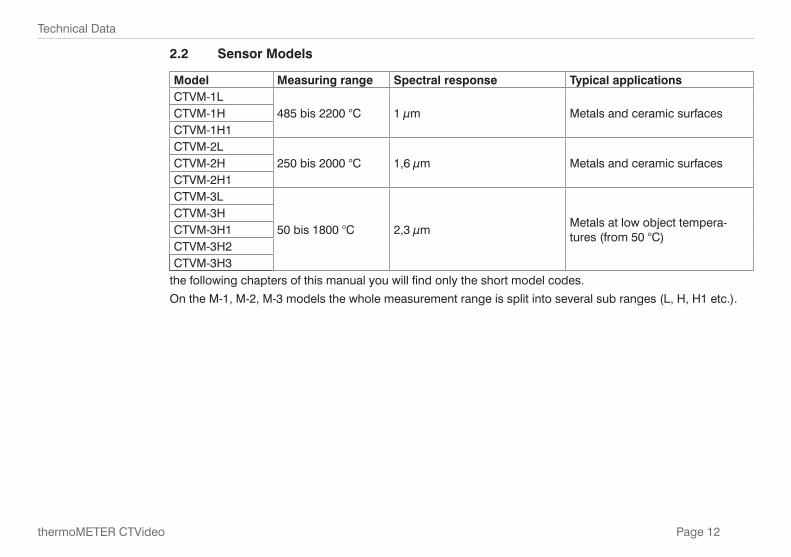
2.2 Sensor Models
Model Measuring range Spectral response Typical applicationsCTVM-1L
485 bis 2200 °C 1 μm Metals and ceramic surfacesCTVM-1HCTVM-1H1CTVM-2L
250 bis 2000 °C 1,6 μm Metals and ceramic surfacesCTVM-2HCTVM-2H1CTVM-3L
50 bis 1800 °C 2,3 μmMetals at low object tempera-tures (from 50 °C)
CTVM-3HCTVM-3H1CTVM-3H2CTVM-3H3
the following chapters of this manual you will find only the short model codes.
On the M-1, M-2, M-3 models the whole measurement range is split into several sub ranges (L, H, H1 etc.).
Page 13
Technical Data
thermoMETER CTVideo
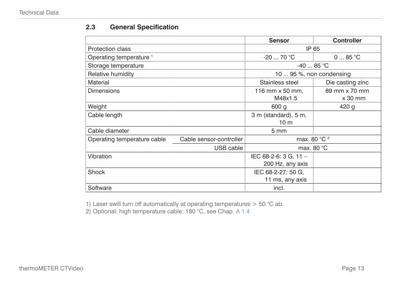
2.3 General Specification
Sensor ControllerProtection class IP 65Operating temperature 1 -20 ... 70 °C 0 ... 85 °CStorage temperature -40 ... 85 °CRelative humidity 10 ... 95 %, non condensingMaterial Stainless steel Die casting zincDimensions 116 mm x 50 mm,
M48x1.589 mm x 70 mm
x 30 mmWeight 600 g 420 gCable length 3 m (standard), 5 m,
10 mCable diameter 5 mmOperating temperature cable Cable sensor-controller max. 80 °C 2
USB cable max. 80 °CVibration IEC 68-2-6: 3 G, 11 –
200 Hz, any axisShock IEC 68-2-27: 50 G,
11 ms, any axisSoftware incl.
1) Laser swill turn off automatically at operating temperatures > 50 °C ab.2) Optional: high temperature cable: 180 °C, see Chap. A 1.4
Page 14
Technical Data
thermoMETER CTVideo
2.4 Electrical Specification
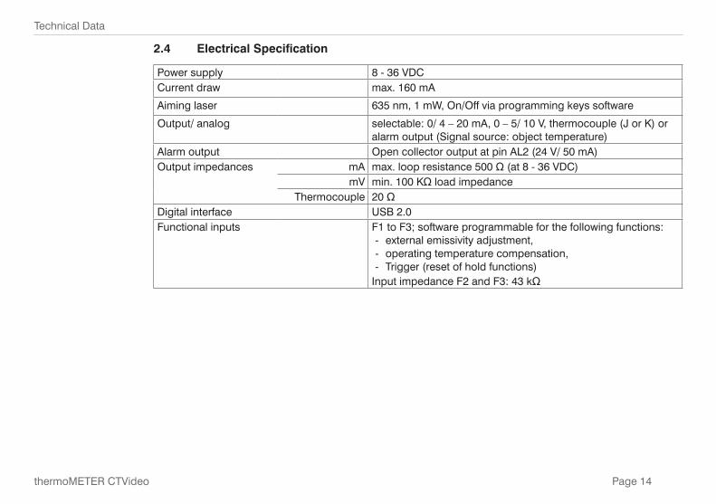
Power supply 8 - 36 VDCCurrent draw max. 160 mA
Aiming laser 635 nm, 1 mW, On/Off via programming keys software
Output/ analog selectable: 0/ 4 – 20 mA, 0 – 5/ 10 V, thermocouple (J or K) or alarm output (Signal source: object temperature)
Alarm output Open collector output at pin AL2 (24 V/ 50 mA)Output impedances mA max. loop resistance 500 Ω (at 8 - 36 VDC)
mV min. 100 KΩ load impedanceThermocouple 20 Ω
Digital interface USB 2.0Functional inputs F1 to F3; software programmable for the following functions:
- external emissivity adjustment, - operating temperature compensation, - Trigger (reset of hold functions)
Input impedance F2 and F3: 43 kΩ
Page 15
Technical Data
thermoMETER CTVideo
2.5 Measurement Specification
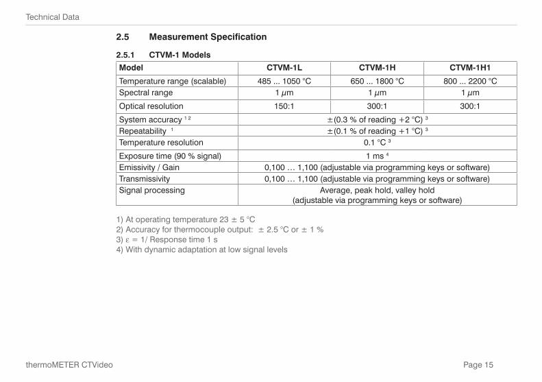
2.5.1 CTVM-1 Models
Model CTVM-1L CTVM-1H CTVM-1H1
Temperature range (scalable) 485 ... 1050 °C 650 ... 1800 °C 800 ... 2200 °CSpectral range 1 μm 1 μm 1 μm
Optical resolution 150:1 300:1 300:1
System accuracy 1 2 ±(0.3 % of reading +2 °C) 3
Repeatability 1 ±(0.1 % of reading +1 °C) 3
Temperature resolution 0.1 °C 3
Exposure time (90 % signal) 1 ms 4
Emissivity / Gain 0,100 … 1,100 (adjustable via programming keys or software)Transmissivity 0,100 … 1,100 (adjustable via programming keys or software)Signal processing Average, peak hold, valley hold
(adjustable via programming keys or software)
1) At operating temperature 23 ± 5 °C2) Accuracy for thermocouple output: ± 2.5 °C or ± 1 %3) e = 1/ Response time 1 s4) With dynamic adaptation at low signal levels
Page 16
Technical Data
thermoMETER CTVideo
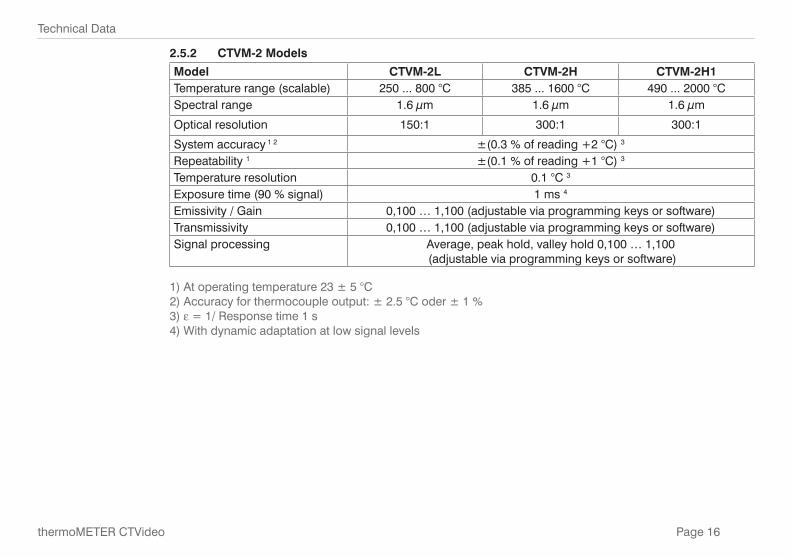
2.5.2 CTVM-2 Models
Model CTVM-2L CTVM-2H CTVM-2H1Temperature range (scalable) 250 ... 800 °C 385 ... 1600 °C 490 ... 2000 °CSpectral range 1.6 μm 1.6 μm 1.6 μm
Optical resolution 150:1 300:1 300:1
System accuracy 1 2 ±(0.3 % of reading +2 °C) 3
Repeatability 1 ±(0.1 % of reading +1 °C) 3
Temperature resolution 0.1 °C 3
Exposure time (90 % signal) 1 ms 4
Emissivity / Gain 0,100 … 1,100 (adjustable via programming keys or software)Transmissivity 0,100 … 1,100 (adjustable via programming keys or software)Signal processing Average, peak hold, valley hold 0,100 … 1,100
(adjustable via programming keys or software)
1) At operating temperature 23 ± 5 °C2) Accuracy for thermocouple output: ± 2.5 °C oder ± 1 %3) e = 1/ Response time 1 s4) With dynamic adaptation at low signal levels
Page 17
Technical Data
thermoMETER CTVideo
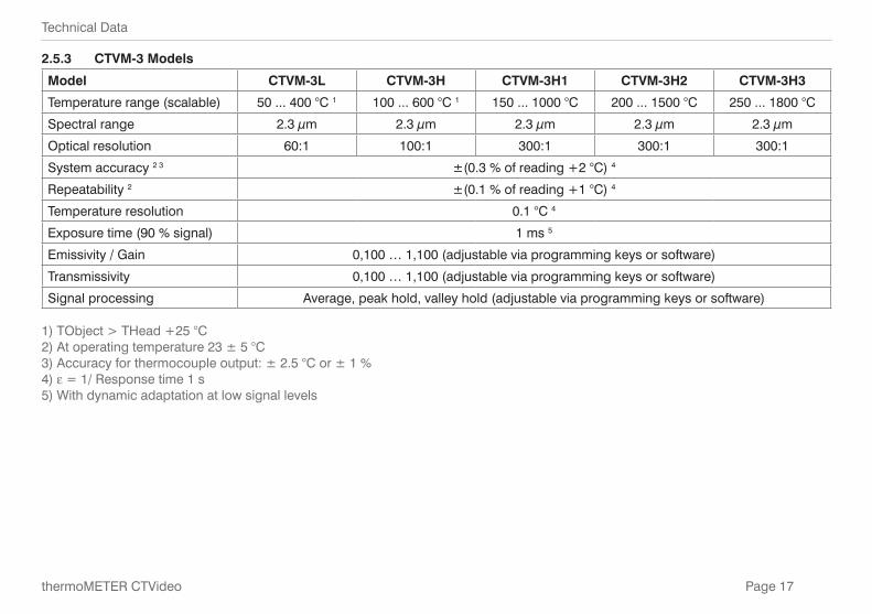
2.5.3 CTVM-3 Models
Model CTVM-3L CTVM-3H CTVM-3H1 CTVM-3H2 CTVM-3H3
Temperature range (scalable) 50 ... 400 °C 1 100 ... 600 °C 1 150 ... 1000 °C 200 ... 1500 °C 250 ... 1800 °C
Spectral range 2.3 μm 2.3 μm 2.3 μm 2.3 μm 2.3 μm
Optical resolution 60:1 100:1 300:1 300:1 300:1
System accuracy 2 3 ±(0.3 % of reading +2 °C) 4
Repeatability 2 ±(0.1 % of reading +1 °C) 4
Temperature resolution 0.1 °C 4
Exposure time (90 % signal) 1 ms 5
Emissivity / Gain 0,100 … 1,100 (adjustable via programming keys or software)
Transmissivity 0,100 … 1,100 (adjustable via programming keys or software)
Signal processing Average, peak hold, valley hold (adjustable via programming keys or software)
1) TObject > THead +25 °C2) At operating temperature 23 ± 5 °C3) Accuracy for thermocouple output: ± 2.5 °C or ± 1 %4) e = 1/ Response time 1 s 5) With dynamic adaptation at low signal levels
Page 18
Delivery
thermoMETER CTVideo
3. Delivery
3.1 Unpacking
1 thermoMETER CTVideo infrared sensor with connection cable and controller
1 Mounting nut and mounting bracket (fixed)
1 USB interface cable
1 CompactConnect Software-CD
1 Instruction manual
Check the delivery for completeness and shipping damage immediately after unpacking. In case of damage or missing parts, please contact the manufacturer or supplier immediately.
You will find optional accessories in appendix, see Chap. A 1.
3.2 Storage - Storage temperature: -40 ... 85 °C (-40 ... +185 °F) - Humidity: 10 ... 95 %, non-condensing
Page 19
Optics
thermoMETER CTVideo
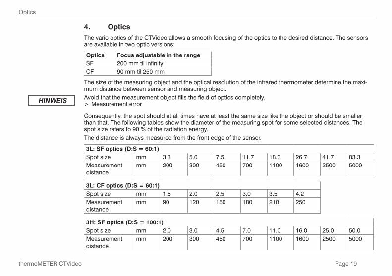
4. OpticsThe vario optics of the CTVideo allows a smooth focusing of the optics to the desired distance. The sensors are available in two optic versions:
Optics Focus adjustable in the rangeSF 200 mm til infinityCF 90 mm til 250 mm
The size of the measuring object and the optical resolution of the infrared thermometer determine the maxi-mum distance between sensor and measuring object.Avoid that the measurement object fills the field of optics completely.
> Measurement error
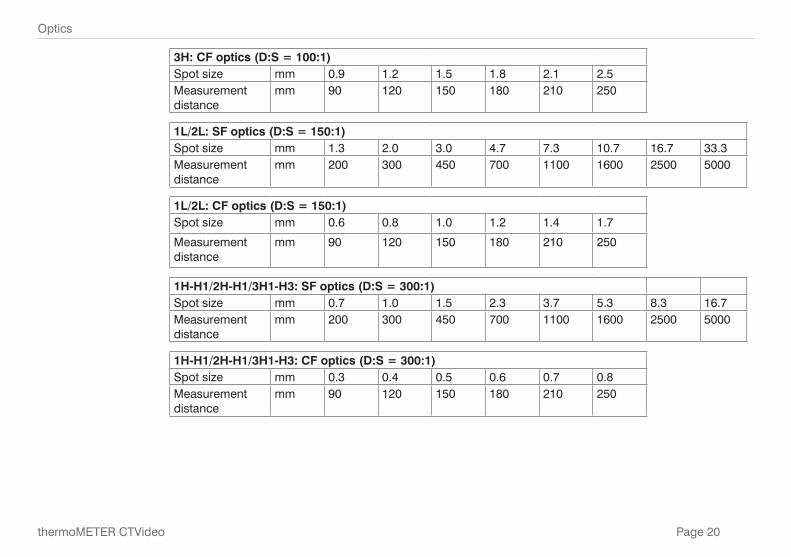
Consequently, the spot should at all times have at least the same size like the object or should be smaller than that. The following tables show the diameter of the measuring spot for some selected distances. The spot size refers to 90 % of the radiation energy.The distance is always measured from the front edge of the sensor.
3L: SF optics (D:S = 60:1)Spot size mm 3.3 5.0 7.5 11.7 18.3 26.7 41.7 83.3Measurement distance
mm 200 300 450 700 1100 1600 2500 5000
3L: CF optics (D:S = 60:1)Spot size mm 1.5 2.0 2.5 3.0 3.5 4.2Measurement distance
mm 90 120 150 180 210 250
3H: SF optics (D:S = 100:1)Spot size mm 2.0 3.0 4.5 7.0 11.0 16.0 25.0 50.0Measurement distance
mm 200 300 450 700 1100 1600 2500 5000
Page 20
Optics
thermoMETER CTVideo
3H: CF optics (D:S = 100:1)Spot size mm 0.9 1.2 1.5 1.8 2.1 2.5Measurement distance
mm 90 120 150 180 210 250
1L/2L: SF optics (D:S = 150:1)Spot size mm 1.3 2.0 3.0 4.7 7.3 10.7 16.7 33.3Measurement distance
mm 200 300 450 700 1100 1600 2500 5000
1L/2L: CF optics (D:S = 150:1)Spot size mm 0.6 0.8 1.0 1.2 1.4 1.7
Measurement distance
mm 90 120 150 180 210 250
1H-H1/2H-H1/3H1-H3: SF optics (D:S = 300:1)Spot size mm 0.7 1.0 1.5 2.3 3.7 5.3 8.3 16.7Measurement distance
mm 200 300 450 700 1100 1600 2500 5000
1H-H1/2H-H1/3H1-H3: CF optics (D:S = 300:1)Spot size mm 0.3 0.4 0.5 0.6 0.7 0.8Measurement distance
mm 90 120 150 180 210 250
Page 21
Mechanical Installation
thermoMETER CTVideo
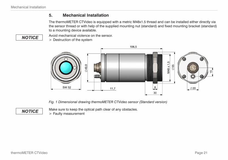
5. Mechanical Installation
The thermoMETER CTVideo is equipped with a metric M48x1.5 thread and can be installed either directly via the sensor thread or with help of the supplied mounting nut (standard) and fixed mounting bracket (standard) to a mounting device available.
Avoid mechanical violence on the sensor. > Destruction of the system
Fig. 1 Dimensional drawing thermoMETER CTVideo sensor (Standard version)
Make sure to keep the optical path clear of any obstacles. > Faulty measurement
Page 22
Mechanical Installation
thermoMETER CTVideo
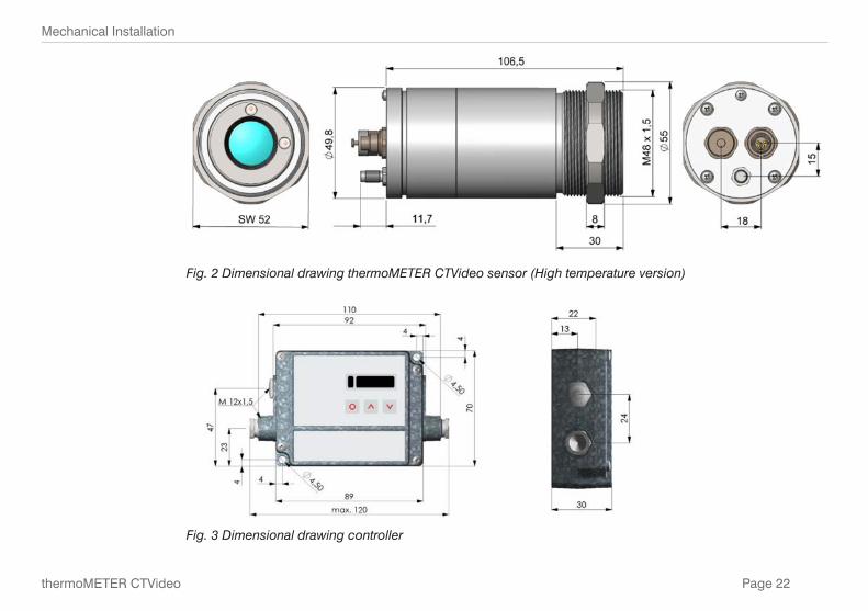
Fig. 2 Dimensional drawing thermoMETER CTVideo sensor (High temperature version)
Fig. 3 Dimensional drawing controller
Page 23
Mechanical Installation
thermoMETER CTVideo
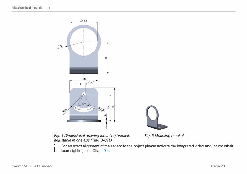
Fig. 4 Dimensional drawing mounting bracket, adjustable in one axis (TM-FB-CTL)
Fig. 5 Mounting bracket
i For an exact alignment of the sensor to the object please activate the integrated video and/ or crosshair laser sighting, see Chap. 9.4.
Page 24
Electrical Installation
thermoMETER CTVideo
6. Electrical Installation
6.1 Cable Connections
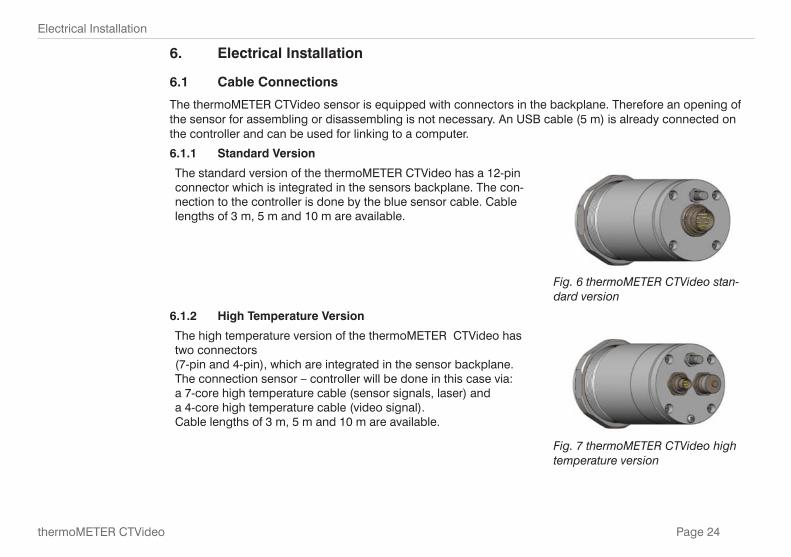
The thermoMETER CTVideo sensor is equipped with connectors in the backplane. Therefore an opening of the sensor for assembling or disassembling is not necessary. An USB cable (5 m) is already connected on the controller and can be used for linking to a computer.
6.1.1 Standard Version
The standard version of the thermoMETER CTVideo has a 12-pin connector which is integrated in the sensors backplane. The con-nection to the controller is done by the blue sensor cable. Cable lengths of 3 m, 5 m and 10 m are available.
Fig. 6 thermoMETER CTVideo stan-dard version
6.1.2 High Temperature Version
The high temperature version of the thermoMETER CTVideo has two connectors(7-pin and 4-pin), which are integrated in the sensor backplane. The connection sensor – controller will be done in this case via:a 7-core high temperature cable (sensor signals, laser) anda 4-core high temperature cable (video signal).Cable lengths of 3 m, 5 m and 10 m are available.
Fig. 7 thermoMETER CTVideo high temperature version
Page 25
Electrical Installation
thermoMETER CTVideo
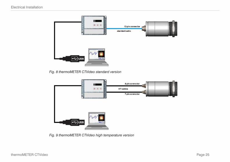
Fig. 8 thermoMETER CTVideo standard version
Fig. 9 thermoMETER CTVideo high temperature version
Page 26
Electrical Installation
thermoMETER CTVideo
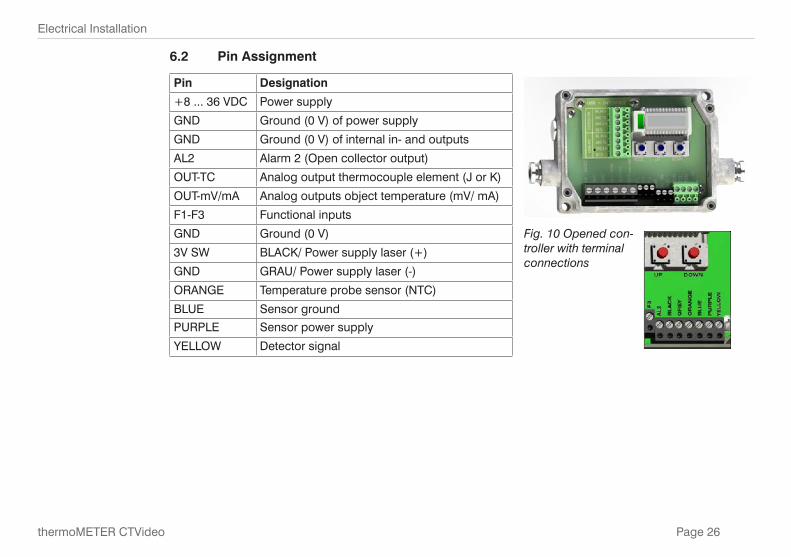
6.2 Pin Assignment
Pin Designation
+8 ... 36 VDC Power supply
GND Ground (0 V) of power supply
GND Ground (0 V) of internal in- and outputs
AL2 Alarm 2 (Open collector output)
OUT-TC Analog output thermocouple element (J or K)
OUT-mV/mA Analog outputs object temperature (mV/ mA)
F1-F3 Functional inputs
GND Ground (0 V) Fig. 10 Opened con-troller with terminal connections
3V SW BLACK/ Power supply laser (+)
GND GRAU/ Power supply laser (-)
ORANGE Temperature probe sensor (NTC)
BLUE Sensor ground
PURPLE Sensor power supply
YELLOW Detector signal
Page 27
Electrical Installation
thermoMETER CTVideo
6.3 Power Supply
Please use a separate, stabilized power supply unit with an output voltage of 5 – 28 VDC which can supply 160 mA. The ripple should be max. 200 mV.
i Please use shielded cables only for all power supply and data lines. The sensor shield has no to be grounded.
Never connect a supply voltage. > Destruction of the output
The thermoMETER CTVideo is not a 2-wire sensor.
Page 28
Electrical Installation
thermoMETER CTVideo
6.4 Cable Mounting
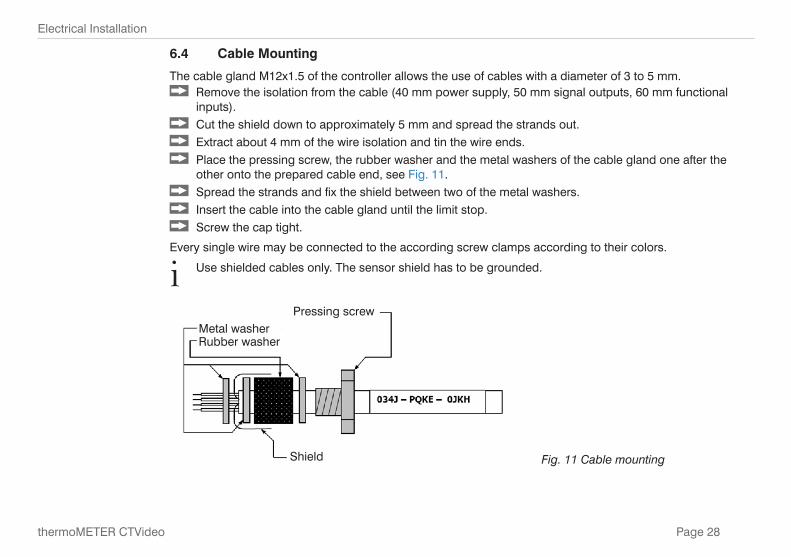
The cable gland M12x1.5 of the controller allows the use of cables with a diameter of 3 to 5 mm. Remove the isolation from the cable (40 mm power supply, 50 mm signal outputs, 60 mm functional
inputs). Cut the shield down to approximately 5 mm and spread the strands out. Extract about 4 mm of the wire isolation and tin the wire ends. Place the pressing screw, the rubber washer and the metal washers of the cable gland one after the
other onto the prepared cable end, see Fig. 11. Spread the strands and fix the shield between two of the metal washers. Insert the cable into the cable gland until the limit stop. Screw the cap tight.
Every single wire may be connected to the according screw clamps according to their colors.
i Use shielded cables only. The sensor shield has to be grounded.
Pressing screwMetal washerRubber washer
Shield Fig. 11 Cable mounting
Page 29
Electrical Installation
thermoMETER CTVideo
6.5 Ground Connection
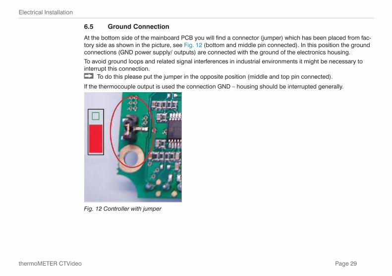
At the bottom side of the mainboard PCB you will find a connector (jumper) which has been placed from fac-tory side as shown in the picture, see Fig. 12 (bottom and middle pin connected). In this position the ground connections (GND power supply/ outputs) are connected with the ground of the electronics housing.
To avoid ground loops and related signal interferences in industrial environments it might be necessary to interrupt this connection.
To do this please put the jumper in the opposite position (middle and top pin connected).
If the thermocouple output is used the connection GND – housing should be interrupted generally.
Fig. 12 Controller with jumper
Page 30
Sensor Calibration Code
thermoMETER CTVideo
7. Sensor Calibration Code
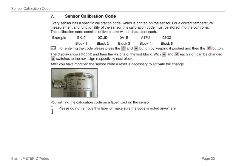
Every sensor has a specific calibration code, which is printed on the sensor. For a correct temperature measurement and functionality of the sensor this calibration code must be stored into the controller. The calibration code consists of five blocks with 4 characters each.
Example EKJ0 - 0OUD - 0A1B - A17U - 93OZ
Block 1 Block 2 Block 3 Block 4 Block 5 For entering the code please press the and button by keeping it pushed and then the button.
The display shows HCODE and then the 4 signs of the first block. With and each sign can be changed; switches to the next sign respectively next block.
After you have modified the sensor code a reset is necessary to activate the change
You will find the calibration code on a label fixed on the sensor.
i Please do not remove this label or make sure the code is noted anywhere.
Page 31
Outputs and Inputs
thermoMETER CTVideo
8. Outputs and Inputs
8.1 Analog Output
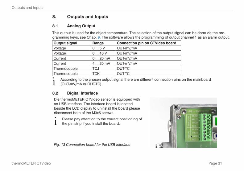
This output is used for the object temperature. The selection of the output signal can be done via the pro-gramming keys, see Chap. 9. The software allows the programming of output channel 1 as an alarm output.
Output signal Range Connection pin on CTVideo boardVoltage 0 ... 5 V OUT-mV/mAVoltage 0 ... 10 V OUT-mV/mACurrent 0 ... 20 mA OUT-mV/mACurrent 4 ... 20 mA OUT-mV/mAThermocouple TCJ OUT-TCThermocouple TCK OUT-TC
i According to the chosen output signal there are different connection pins on the mainboard (OUT-mV/mA or OUT-TC).
8.2 Digital InterfaceDie thermoMETER CTVideo sensor is equipped with an USB interface. The interface board is located beside the LCD display to uninstall the board please disconnect both of the M3x5 screws.
i Please pay attention to the correct positioning of the pin strip if you install the board.
Fig. 13 Connection board for the USB interface
Page 32
Outputs and Inputs
thermoMETER CTVideo
8.3 Functional Inputs
The three functional inputs F1 to F3 can be programmed with the software, only.
F1 (digital) Trigger (a 0 V - level on F1 resets the hold functions)
F2 (analog) External emissivity adjustment (0 - 10 V: 0 V e = 0.1; 9 V e = 1; 10 V e = 1.1)
F3 (analog) External compensation of operating temperature/ the range is scalable via software. (0 - 10 V -40 - 900 °C/ preset range: -20 - 200 °C)
F1-F3 (digital) Emissivity (digital choice via table) A non-connected input represents: F1 = High /F2, F3 = Low (High level: ≥+3 V ... +36 V / Low level: ≤ +0.4 V ... -36 V)
8.4 Alarms
The thermoMETER CTVideo has the following Alarm features:
All alarms (alarm 1, alarm 2, output channel 1 and 2 if used as alarm output) have a fixed hysterese of 2 K.
8.4.1 Output Channel 1
To activate the alarm function the output channel has to be switched into digital mode. For this purpose the software is required.
Page 33
Outputs and Inputs
thermoMETER CTVideo
8.4.2 Visual Alarms
These alarms will cause a change of the color of the LCD display and will also change the status of the optional relays interface. In addition the Alarm 2 can be used as open collector output at pin AL2 on the main-board (24 V/ 50 mA).
From factory side the alarms are defined as follows:
Alarm 1 Norm. closed/ Low-Alarm Alarm 2 Norm. open/ High-Alarm
Both of these alarms will have effect on the LCD color:
BLUE Alarm 1 activeRED Alarm 2 activeGREEN No alarm active
Extended setup like definition as low or high alarm (via change of normally open/ closed), selection of the signal source (TObj, THead, TBox) can be done with the software.

Page 34
Operation
thermoMETER CTVideo
9. Operation
After power up the unit the sensor starts an initializing routine for some seconds. During this time the display will show INIT. After this procedure the object temperature is shown in the display. The display backlight color changes according to the alarm settings, see Chap. 8.4.
9.1 Restoring Factory Setting To set the thermoMETER CTVideo back to the factory default settings, please press at first the button
and then the button and keep both pressed for approx. 3 seconds.
The display will show RESET for confirmation.
Display Modus (Example) Adjustment Range
S ON Laser Sighting (On) ON/OFF142.3C Object temperature (after signal processing)
(142.3 °C)Fixed
127CH Sensor temperature (127 °C) Fixed25CB Box temperature (25 °C) Fixed142CA Actual object temperature (142 °C) Fixed
MV5 Signal output channel 1 (0 - 5 V) 0 - 20 = 0 - 20 mA/
4 - 20 = 4 - 20 mA/
MV5 = 0 - 5 V/
MV10 = 0 - 10 V/
TCJ = Thermo couple type J/
TCK = Thermo couple type KE0.970 Emissivity (0,970) 0,100 ... 1,100
T1.000 Transmissivity (1,000) 0,100 ... 1,100
A 0.2 Signal output Average (0.2 s) A---- = inactive/0,1 ... 999,9 s
P---- Signal output Peak hold (inactive) P---- = inactive/0,1 ... 999,9 s/P ∞ ∞ ∞ ∞ = infinite
Page 35
Operation
thermoMETER CTVideo
Display Modus (Example) Adjustment Range
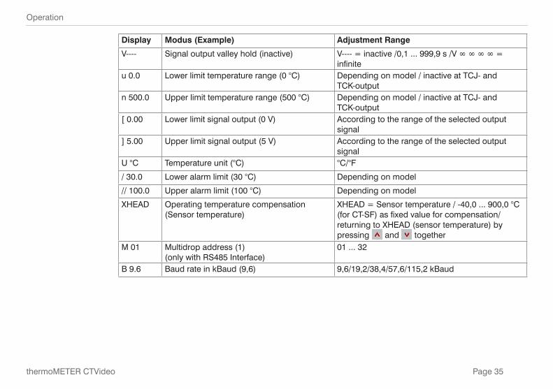
V---- Signal output valley hold (inactive) V---- = inactive /0,1 ... 999,9 s /V ∞ ∞ ∞ ∞ = infinite
u 0.0 Lower limit temperature range (0 °C) Depending on model / inactive at TCJ- and TCK-output
n 500.0 Upper limit temperature range (500 °C) Depending on model / inactive at TCJ- and TCK-output
[ 0.00 Lower limit signal output (0 V) According to the range of the selected output signal
] 5.00 Upper limit signal output (5 V) According to the range of the selected output signal
U °C Temperature unit (°C) °C/°F
/ 30.0 Lower alarm limit (30 °C) Depending on model
// 100.0 Upper alarm limit (100 °C) Depending on model
XHEAD Operating temperature compensation (Sensor temperature)
XHEAD = Sensor temperature / -40,0 ... 900,0 °C (for CT-SF) as fixed value for compensation/ returning to XHEAD (sensor temperature) by pressing and together
M 01 Multidrop address (1) (only with RS485 Interface)
01 ... 32
B 9.6 Baud rate in kBaud (9,6) 9,6/19,2/38,4/57,6/115,2 kBaud
Page 36
Operation
thermoMETER CTVideo
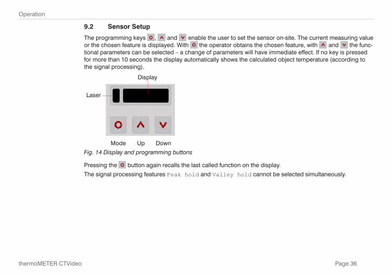
9.2 Sensor Setup
The programming keys , and enable the user to set the sensor on-site. The current measuring value or the chosen feature is displayed. With the operator obtains the chosen feature, with and the func-tional parameters can be selected – a change of parameters will have immediate effect. If no key is pressed for more than 10 seconds the display automatically shows the calculated object temperature (according to the signal processing).
Laser
Mode Up Down
Display
Fig. 14 Display and programming buttons
Pressing the button again recalls the last called function on the display.
The signal processing features Peak hold and Valley hold cannot be selected simultaneously.
Page 37
Operation
thermoMETER CTVideo
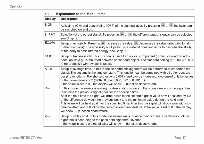
9.3 Explanation to the Menu ItemsDisplay Description
S ON Activating (ON) and deactivating (OFF) of the sighting laser. By pressing or the laser can be switched on and off.
MV5 Selection of the output signal. By pressing or the different output signals can be selected, see Chap. 9.1.
EO.970 Setup of emissivity. Pressing increases the value, decreases the value (also valid for all further functions). The emissivity (e - Epsilon) is a material constant factor to describe the ability of the body to emit infrared energy, see Chap. 13.
T1.000 Setup of transmissivity. This function is used if an optical component (protective window, addi-tional optics e.g.) is mounted between sensor and object. The standard setting is 1.000 = 100 % (if no protective window etc. is used).
A 0.2 Setup of average time. In this mode an arithmetic algorithm will be performed to smoothen the signal. The set time is the time constant. This function can be combined with all other post pro-cessing functions. The shortest value is 0,001 s and can be increased/ decreased only by values of the power series of 2 (0,002, 0,004, 0,008, 0,016, 0,032, ...). If the value is set to 0.0 the display will show --- (function deactivated).
P---- In this mode the sensor is waiting for descending signals. If the signal descends the algorithm maintains the previous signal peak for the specified time. After the hold time the signal will drop down to the second highest value or will descend by 1/8 of the difference between the previous peak and the minimum value during the hold time. This value will be held again for the specified time. After this the signal will drop down with slow time constant and will follow the current object temperature. If the value is set to 0.0 the display will show --- (function deactivated).
V---- Setup of valley hold. In this mode the sensor waits for ascending signals. The definition of the algorithm is according to the peak hold algorithm (inverted). If the value is set to 0.0 the display will show --- (function deactivated).
Page 38
Operation
thermoMETER CTVideo
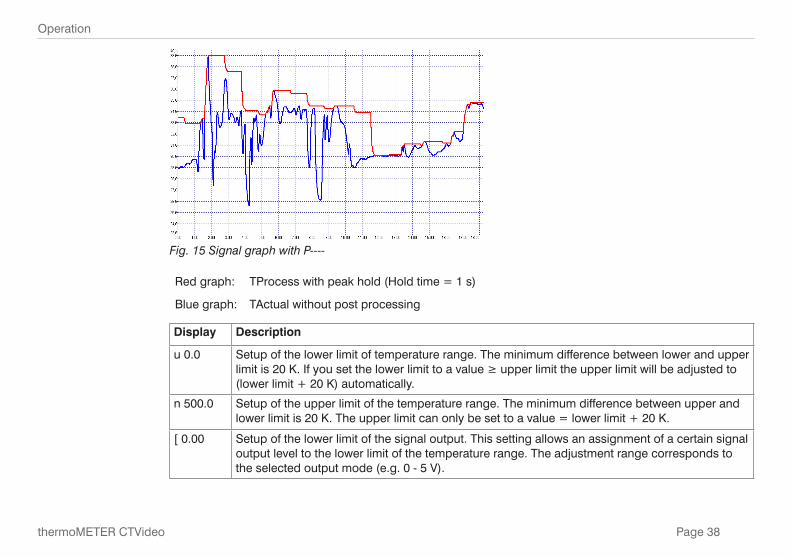
Fig. 15 Signal graph with P----
Red graph: TProcess with peak hold (Hold time = 1 s)
Blue graph: TActual without post processing
Display Description
u 0.0 Setup of the lower limit of temperature range. The minimum difference between lower and upper limit is 20 K. If you set the lower limit to a value ≥ upper limit the upper limit will be adjusted to (lower limit + 20 K) automatically.
n 500.0 Setup of the upper limit of the temperature range. The minimum difference between upper and lower limit is 20 K. The upper limit can only be set to a value = lower limit + 20 K.
[ 0.00 Setup of the lower limit of the signal output. This setting allows an assignment of a certain signal output level to the lower limit of the temperature range. The adjustment range corresponds to the selected output mode (e.g. 0 - 5 V).
Page 39
Operation
thermoMETER CTVideo
Display Description
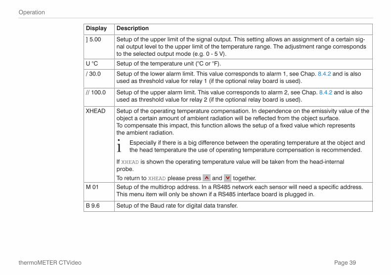
] 5.00 Setup of the upper limit of the signal output. This setting allows an assignment of a certain sig-nal output level to the upper limit of the temperature range. The adjustment range corresponds to the selected output mode (e.g. 0 - 5 V).
U °C Setup of the temperature unit (°C or °F).
/ 30.0 Setup of the lower alarm limit. This value corresponds to alarm 1, see Chap. 8.4.2 and is also used as threshold value for relay 1 (if the optional relay board is used).
// 100.0 Setup of the upper alarm limit. This value corresponds to alarm 2, see Chap. 8.4.2 and is also used as threshold value for relay 2 (if the optional relay board is used).
XHEAD Setup of the operating temperature compensation. In dependence on the emissivity value of the object a certain amount of ambient radiation will be reflected from the object surface. To compensate this impact, this function allows the setup of a fixed value which represents the ambient radiation.
i Especially if there is a big difference between the operating temperature at the object and the head temperature the use of operating temperature compensation is recommended.
If XHEAD is shown the operating temperature value will be taken from the head-internal probe.
To return to XHEAD please press and together.
M 01 Setup of the multidrop address. In a RS485 network each sensor will need a specific address. This menu item will only be shown if a RS485 interface board is plugged in.
B 9.6 Setup of the Baud rate for digital data transfer.
Page 40
Operation
thermoMETER CTVideo
9.4 Visor Options
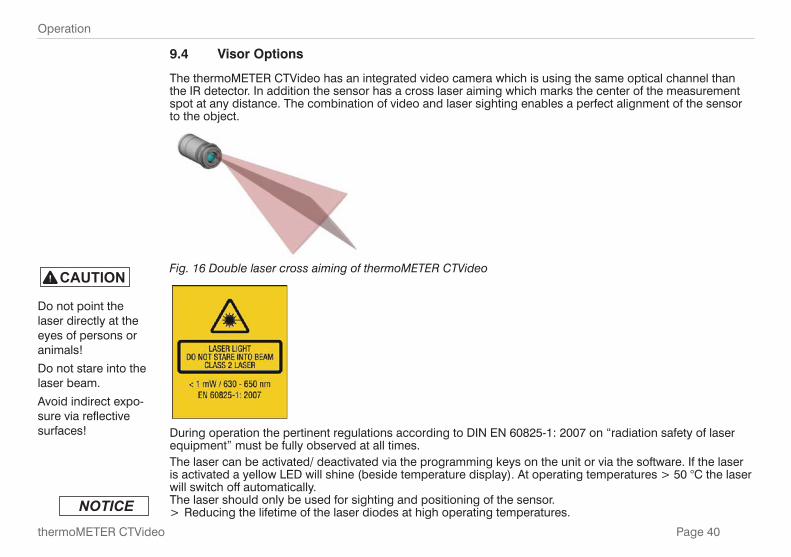
The thermoMETER CTVideo has an integrated video camera which is using the same optical channel than the IR detector. In addition the sensor has a cross laser aiming which marks the center of the measurement spot at any distance. The combination of video and laser sighting enables a perfect alignment of the sensor to the object.
Fig. 16 Double laser cross aiming of thermoMETER CTVideo
During operation the pertinent regulations according to DIN EN 60825-1: 2007 on “radiation safety of laser equipment” must be fully observed at all times.The laser can be activated/ deactivated via the programming keys on the unit or via the software. If the laser is activated a yellow LED will shine (beside temperature display). At operating temperatures > 50 °C the laser will switch off automatically. The laser should only be used for sighting and positioning of the sensor.
> Reducing the lifetime of the laser diodes at high operating temperatures.
Do not point the laser directly at the eyes of persons or animals!
Do not stare into the laser beam.
Avoid indirect expo-sure via reflective surfaces!
Page 41
Operation
thermoMETER CTVideo
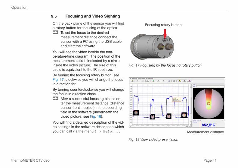
9.5 Focusing and Video Sighting
On the back plane of the sensor you will find a rotary button for focusing of the optics.
To set the focus to the desired measurement distance connect the sensor with a PC using the USB cable and start the software.
You will see the video beside the tem-perature-time diagram. The position of the measurement spot is indicated by a circle inside the video picture. The size of this circle is equivalent to the IR spot size.
By turning the focusing rotary button, see Fig. 17, clockwise you will change the focus in direction far.
By turning counterclockwise you will change the focus in direction close.
After a successful focusing please en-ter the measurement distance (distance sensor front – object) in the according field in the software (underneath the video picture, see Fig. 18).
You will find a detailed description of the vid-eo settings in the software description which you can call via the menu ? > Help....
Focusing rotary button
Fig. 17 Focusing by the focusing rotary button
Measurement distance
Fig. 18 View video presentation
Page 42
Instructions for Operation
thermoMETER CTVideo
9.6 Error Messages
The display of the thermoMETER CTVideo sensor can show the following error messages:
1. digit:
0x No error
1x Sensor temperature probe short circuit to GND
2x Controller temperature too low
4x Controller temperature too high
6x Controller temperature probe disconnected
8x Controller temperature probe short circuit to GND
2. digit:
x0 No error
x2 Object temperature too high
x4 Sensor temperature too low
x8 Sensor temperature too high
xC Sensor temperature probe disconnected (bn)
10. Instructions for Operation
10.1 Cleaning
Lens cleaning: Blow off loose particles using clean compressed air. The lens surface can be cleaned with a soft, humid tissue moistened with water or a water based glass cleaner.
Never use cleaning compounds which contain solvents (neither for the lens nor for the housing). > Destruction of the sensor and/or the controller
Page 43
Software
thermoMETER CTVideo
11. Software
11.1 Installation Insert the CompactConnect installation CD into the according drive on your computer.
If the autorun option is activated the installation wizard will start automatically. Otherwise please start CDset-up.exe from the CDROM.
Follow the instructions of the wizard until the installation is finished.
The installation wizard will place a launch icon on the desktop and in the start menu.
If you want to uninstall the software from your system please use the uninstall icon in the start menu. You will find a detailed software manual on the CD.
11.2 System Requirements - Windows XP, Windows Vista, Windows 7, 8 - USB interface - Hard disc with at least 30 MByte RAM - At least 128 MByte RAM - CD-ROM drive
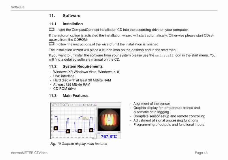
11.3 Main Features
- Alignment of the sensor - Graphic display for temperature trends and
automatic data logging - Complete sensor setup and remote controlling - Adjustment of signal processing functions - Programming of outputs and functional inputs
Fig. 19 Graphic display main features
Page 44
Communication Settings
thermoMETER CTVideo
12. Communication Settings
12.1 Serial Interface
Baud rate: 9.6 ... 115.2 kBaud (adjustable on the unit or via software)
Data bits: 8
Parity: none
Stop bits: 1
Flow control: off
12.2 Protocol
All sensors of the thermoMETER CTVideo series are using a binary protocol. Alternatively they can be switched to an ASCII protocol. To get a fast communication the protocol has no additional overhead with CR, LR or ACK bytes.
12.3 ASCII Protocol
To switch to the ASCII protocol please use the following command:
Decimal: 131
HEX: 0x83
Data, answer: byte 1
Result: 0 – Binary Protocol 1 – ASCII Protocol
Page 45
Communication Settings
thermoMETER CTVideo
12.4 Saving of Parameter Settings
After power on of the thermoMETER CTVideo sensor the flash mode is active. It means, changed parameter settings will be saved in the internal Flash-EEPROM and will be kept also after the sensor is switched off.
In case settings should be changed quite often or continuously the flash mode can be switched off by using the following command:
Decimal: 112
HEX: 0x70
Data, answer: byte 1
Result: 1 – Data will be written into the flash memory 2 – Data will not be written into the flash memory
If the flash mode is deactivated, all settings will only be kept as long as the CTVideo unit is powered. If the unit is switched off and powered on again all previous settings are lost.
The command 0x71 will poll the current status.
You will find a detailed protocol and command description on the software CD in the directory: \Commands.
Page 46
Communication Settings
thermoMETER CTVideo
12.5 Basics of Infrared Thermometry
Depending on the temperature of the object is accompanied by a change in the intensity of the radiation. For the measurement of “thermal radiation” infrared thermometry uses a wave-length ranging between 1 μ and 20 μm. The intensity of the emitted radiation depends on the material. This material contingent constant is described with the help of the emissivity which is a known value for most materials, see Chap. 13.
Infrared thermometers are optoelectronic sensors. They calculate the surface temperature on the basis of the emitted infrared radiation from an object. The most important feature of infrared thermometers is that they en-able the user to measure objects contactless. Consequently, these products help to measure the temperature of inaccessible or moving objects without difficulties. Infrared thermometers basically consist of the following components:
- Lens - Spectral filter - Detector - Controller (amplifier/ linearization/ signal processing)
The specifications of the lens decisively determine the optical path of the infrared thermometer, which is char-acterized by the ratio Distance to Spot size. The spectral filter selects the wavelength range, which is relevant for the temperature measurement. The detector in cooperation with the processing electronics transforms the emitted infrared radiation into electrical signals.
Page 47
Emissivity
thermoMETER CTVideo
13. Emissivity
13.1 Definition
The intensity of infrared radiation, which is emitted by each body, depends on the temperature as well as on the radiation features of the surface material of the measuring object. The emissivity (e – Epsilon) is used as a material constant factor to describe the ability of the body to emit infrared energy. It can range between 0 and 100 %. A “blackbody” is the ideal radiation source with an emissivity of 1,0 whereas a mirror shows an emissivity of 0,1.
If the emissivity chosen is too high, the infrared thermometer may display a temperature value which is much lower than the real temperature – assuming the measuring object is warmer than its surroundings. A low emissivity (reflective surfaces) carries the risk of inaccurate measuring results by interfering infrared radiation emitted by background objects (flames, heating systems, chamotte). To minimize measuring errors in such cases, the handling should be performed very carefully and the unit should be protected against reflecting radiation sources.
13.2 Determination of Unknown Emissivity - First, determine the actual temperature of the measuring object with a thermocouple or contact sensor.
Secondly, measure the temperature with the infrared thermometer and modify the emissivity until the dis-played result corresponds to the actual temperature.
- If you monitor temperatures of up to 380 °C you may place a special plastic sticker onto the measuring object, which covers it completely. Now set the emissivity to 0,95 and take the temperature of the sticker. Afterwards, determine the temperature of the adjacent area on the measuring object and adjust the
emissivity according to the value of the temperature of the sticker. - Cove a part of the surface of the measuring object with black, flat paint with an emissivity of 0,98.
Adjust the emissivity of your infrared thermometer to 0,98 and take the temperature of the colored sur-face.
Afterwards, determine the temperature of a directly adjacent area and modify the emissivity until the measured value corresponds to the temperature of the colored surface.
i On all three methods the object temperature must be different from the operating temperature.
Page 48
Emissivity
thermoMETER CTVideo
13.3 Characteristic Emissivities
In case none of the methods mentioned above help to determine the emissivity you may use the emissivity tables, see Chap. A 3, see Chap. A 4. These are average values, only. The actual emissivity of a material depends on the following factors:
- Temperature - Measuring angle - Geometry of the surface (flat, convex, concave) - Thickness of the material - Constitution of the surface (polished, oxidized, rough, sandblast) - Spectral range of the measurement - Transmissivity (e.g. with thin films)
Page 49
Warranty
thermoMETER CTVideo
14. Warranty
All components of the device have been checked and tested for perfect function in the factory. In the unlikely event that errors should occur despite our thorough quality control, this should be reported immediately to MICRO-EPSILON.
The warranty period lasts 12 months following the day of shipment. Defective parts, except wear parts, will be repaired or replaced free of charge within this period if you return the device free of cost to MICRO-EPSILON. This warranty does not apply to damage resulting from abuse of the equipment and devices, from forceful handling or installation of the devices or from repair or modifications performed by third parties.
No other claims, except as warranted, are accepted. The terms of the purchasing contract apply in full. MICRO-EPSILON will specifically not be responsible for eventual consequential damages. MICRO-EPSILON always strives to supply the customers with the finest and most advanced equipment. Development and re-finement is therefore performed continuously and the right to design changes without prior notice is accord-ingly reserved.
For translations in other languages, the data and statements in the German language operation manual are to be taken as authoritative.
Page 50
Service, Repair
thermoMETER CTVideo
15. Service, Repair
In the event of a defect on the infrared sensor, please send us the affected parts for repair or exchange.
In the case of faults the cause of which is not clear-ly identifiable, the entire measuring system must be sent back to:
MICRO-EPSILON MESSTECHNIK GmbH & Co. KG Königbacher Str. 15 94496 Ortenburg / Germany
Tel. +49 (0) 8542/ 168-0 Fax +49 (0) 8542 / 168-90 [email protected]
For customers in USA applies:
Send the affected parts or the entire measuring system back to:
MICRO-EPSILON USA 8120 Brownleigh Dr. Raleigh, NC 27617 /USA
Tel. +1 919 / 787-9707 Fax +1 919 / 787-9706 [email protected] www.micro-epsilon.com
For customers in Canada or South America applies:
Please contact your local distributor.
16. Decommissioning, Disposal Disconnect the USB cable from the infrared sensor.
The thermoMETER CTVideo is produced according to the directive 2011/65/EU, “RoHS“. Do the disposal according to the legal regulations (see directive 2002/96/EC).
Page 51
Anhang | Accessories
thermoMETER CTVideo
Appendix
A 1 Accessories
A 1.1 Air Purge Collar
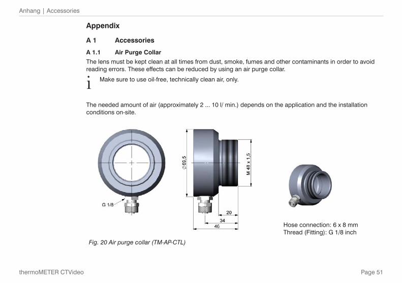
The lens must be kept clean at all times from dust, smoke, fumes and other contaminants in order to avoid reading errors. These effects can be reduced by using an air purge collar.
i Make sure to use oil-free, technically clean air, only.
The needed amount of air (approximately 2 ... 10 l/ min.) depends on the application and the installation conditions on-site.
Hose connection: 6 x 8 mm Thread (Fitting): G 1/8 inch
Fig. 20 Air purge collar (TM-AP-CTL)
Page 52
Anhang | Accessories
thermoMETER CTVideo
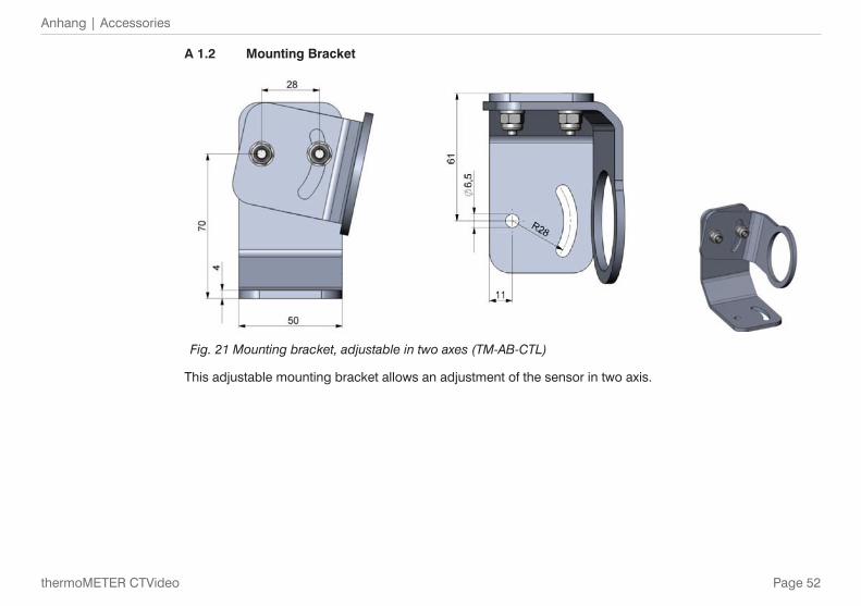
A 1.2 Mounting Bracket
Fig. 21 Mounting bracket, adjustable in two axes (TM-AB-CTL)
This adjustable mounting bracket allows an adjustment of the sensor in two axis.
Page 53
Anhang | Accessories
thermoMETER CTVideo
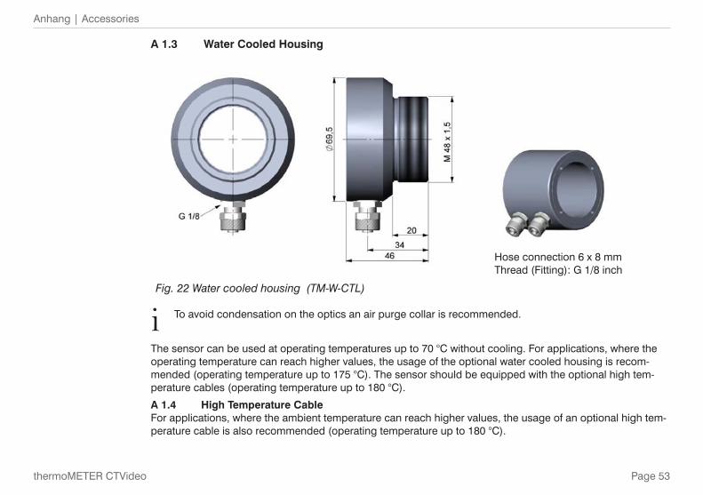
A 1.3 Water Cooled Housing
Hose connection 6 x 8 mm Thread (Fitting): G 1/8 inch
Fig. 22 Water cooled housing (TM-W-CTL)
i To avoid condensation on the optics an air purge collar is recommended.
The sensor can be used at operating temperatures up to 70 °C without cooling. For applications, where the operating temperature can reach higher values, the usage of the optional water cooled housing is recom-mended (operating temperature up to 175 °C). The sensor should be equipped with the optional high tem-perature cables (operating temperature up to 180 °C).
A 1.4 High Temperature CableFor applications, where the ambient temperature can reach higher values, the usage of an optional high tem-perature cable is also recommended (operating temperature up to 180 °C).
Page 54
Anhang | Accessories
thermoMETER CTVideo
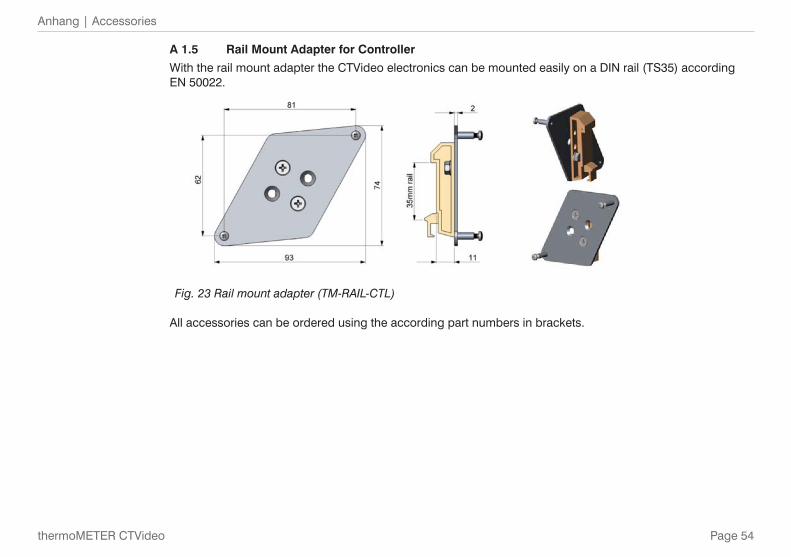
A 1.5 Rail Mount Adapter for Controller
With the rail mount adapter the CTVideo electronics can be mounted easily on a DIN rail (TS35) according EN 50022.
Fig. 23 Rail mount adapter (TM-RAIL-CTL)
All accessories can be ordered using the according part numbers in brackets.
Page 55
Anhang | Factory Default Settings
thermoMETER CTVideo
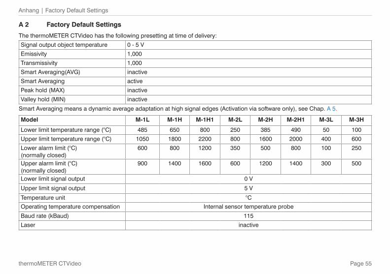
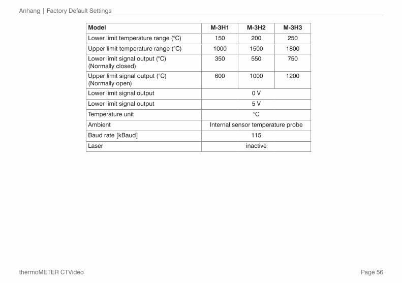
A 2 Factory Default Settings
The thermoMETER CTVideo has the following presetting at time of delivery:
Signal output object temperature 0 - 5 V
Emissivity 1,000
Transmissivity 1,000
Smart Averaging(AVG) inactive
Smart Averaging active
Peak hold (MAX) inactive
Valley hold (MIN) inactive
Smart Averaging means a dynamic average adaptation at high signal edges (Activation via software only), see Chap. A 5.
Model M-1L M-1H M-1H1 M-2L M-2H M-2H1 M-3L M-3H
Lower limit temperature range (°C) 485 650 800 250 385 490 50 100
Upper limit temperature range (°C) 1050 1800 2200 800 1600 2000 400 600
Lower alarm limit (°C) (normally closed)
600 800 1200 350 500 800 100 250
Upper alarm limit (°C) (normally closed)
900 1400 1600 600 1200 1400 300 500
Lower limit signal output 0 V
Upper limit signal output 5 V
Temperature unit °C
Operating temperature compensation Internal sensor temperature probe
Baud rate (kBaud) 115
Laser inactive
Page 56
Anhang | Factory Default Settings
thermoMETER CTVideo
Model M-3H1 M-3H2 M-3H3
Lower limit temperature range (°C) 150 200 250
Upper limit temperature range (°C) 1000 1500 1800
Lower limit signal output (°C) (Normally closed)
350 550 750
Upper limit signal output (°C) (Normally open)
600 1000 1200
Lower limit signal output 0 V
Lower limit signal output 5 V
Temperature unit °C
Ambient Internal sensor temperature probe
Baud rate [kBaud] 115
Laser inactive
Page 57
Anhang | Emissivity Table Metals
thermoMETER CTVideo
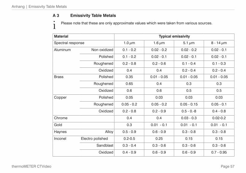
A 3 Emissivity Table Metals
i Please note that these are only approximate values which were taken from various sources.
Material Typical emissivity
Spectral response 1.0 μm 1.6 μm 5.1 μm 8 - 14 μm
Aluminum Non oxidized 0.1 - 0.2 0.02 - 0.2 0.02 - 0.2 0.02 - 0.1
Polished 0.1 - 0.2 0.02 - 0.1 0.02 - 0.1 0.02 - 0.1
Roughened 0.2 - 0.8 0.2 - 0.6 0.1 - 0.4 0.1 - 0.3
Oxidized 0.4 0.4 0.2 - 0.4 0.2 - 0.4
Brass Polished 0.35 0.01 - 0.05 0.01 - 0.05 0.01 - 0.05
Roughened 0.65 0.4 0.3 0.3
Oxidized 0.6 0.6 0.5 0.5
Copper Polished 0.05 0.03 0.03 0.03
Roughened 0.05 - 0.2 0.05 - 0.2 0.05 - 0.15 0.05 - 0.1
Oxidized 0.2 - 0.8 0.2 - 0.9 0.5 - 0.-8 0.4 - 0.8
Chrome 0.4 0.4 0.03 - 0.3 0.02-0.2
Gold 0.3 0.01 - 0.1 0.01 - 0.1 0.01 - 0.1
Haynes Alloy 0.5 - 0.9 0.6 - 0.9 0.3 - 0.8 0.3 - 0.8
Inconel Electro polished 0.2-0.5 0.25 0.15 0.15
Sandblast 0.3 - 0.4 0.3 - 0.6 0.3 - 0.6 0.3 - 0.6
Oxidized 0.4 - 0.9 0.6 - 0.9 0.6 - 0.9 0.7 - 0.95
Page 58
Anhang | Emissivity Table Metals
thermoMETER CTVideo
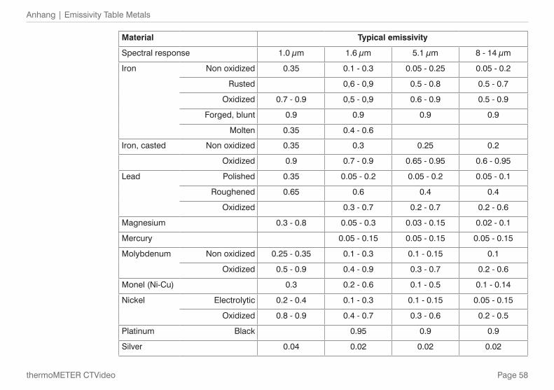
Material Typical emissivity
Spectral response 1.0 μm 1.6 μm 5.1 μm 8 - 14 μm
Iron Non oxidized 0.35 0.1 - 0.3 0.05 - 0.25 0.05 - 0.2
Rusted 0,6 - 0,9 0.5 - 0.8 0.5 - 0.7
Oxidized 0.7 - 0.9 0,5 - 0,9 0.6 - 0.9 0.5 - 0.9
Forged, blunt 0.9 0.9 0.9 0.9
Molten 0.35 0.4 - 0.6
Iron, casted Non oxidized 0.35 0.3 0.25 0.2
Oxidized 0.9 0.7 - 0.9 0.65 - 0.95 0.6 - 0.95
Lead Polished 0.35 0.05 - 0.2 0.05 - 0.2 0.05 - 0.1
Roughened 0.65 0.6 0.4 0.4
Oxidized 0.3 - 0.7 0.2 - 0.7 0.2 - 0.6
Magnesium 0.3 - 0.8 0.05 - 0.3 0.03 - 0.15 0.02 - 0.1
Mercury 0.05 - 0.15 0.05 - 0.15 0.05 - 0.15
Molybdenum Non oxidized 0.25 - 0.35 0.1 - 0.3 0.1 - 0.15 0.1
Oxidized 0.5 - 0.9 0.4 - 0.9 0.3 - 0.7 0.2 - 0.6
Monel (Ni-Cu) 0.3 0.2 - 0.6 0.1 - 0.5 0.1 - 0.14
Nickel Electrolytic 0.2 - 0.4 0.1 - 0.3 0.1 - 0.15 0.05 - 0.15
Oxidized 0.8 - 0.9 0.4 - 0.7 0.3 - 0.6 0.2 - 0.5
Platinum Black 0.95 0.9 0.9
Silver 0.04 0.02 0.02 0.02
Page 59
Anhang | Emissivity Table Metals
thermoMETER CTVideo
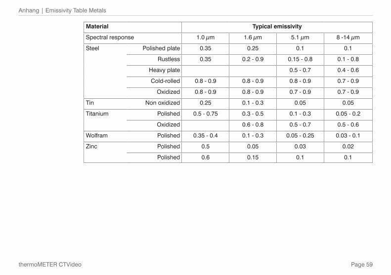
Material Typical emissivity
Spectral response 1.0 μm 1.6 μm 5.1 μm 8 -14 μm
Steel Polished plate 0.35 0.25 0.1 0.1
Rustless 0.35 0.2 - 0.9 0.15 - 0.8 0.1 - 0.8
Heavy plate 0.5 - 0.7 0.4 - 0.6
Cold-rolled 0.8 - 0.9 0.8 - 0.9 0.8 - 0.9 0.7 - 0.9
Oxidized 0.8 - 0.9 0.8 - 0.9 0.7 - 0.9 0.7 - 0.9
Tin Non oxidized 0.25 0.1 - 0.3 0.05 0.05
Titanium Polished 0.5 - 0.75 0.3 - 0.5 0.1 - 0.3 0.05 - 0.2
Oxidized 0.6 - 0.8 0.5 - 0.7 0.5 - 0.6
Wolfram Polished 0.35 - 0.4 0.1 - 0.3 0.05 - 0.25 0.03 - 0.1
Zinc Polished 0.5 0.05 0.03 0.02
Polished 0.6 0.15 0.1 0.1
Page 60
Anhang | Emissivity Table Non Metals
thermoMETER CTVideo
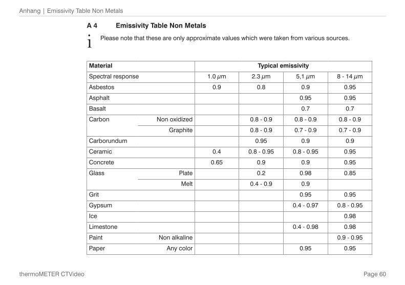
A 4 Emissivity Table Non Metals
i Please note that these are only approximate values which were taken from various sources.
Material Typical emissivity
Spectral response 1.0 μm 2.3 μm 5,1 μm 8 - 14 μm
Asbestos 0.9 0.8 0.9 0.95
Asphalt 0.95 0.95
Basalt 0.7 0.7
Carbon Non oxidized 0.8 - 0.9 0.8 - 0.9 0.8 - 0.9
Graphite 0.8 - 0.9 0.7 - 0.9 0.7 - 0.9
Carborundum 0.95 0.9 0.9
Ceramic 0.4 0.8 - 0.95 0.8 - 0.95 0.95
Concrete 0.65 0.9 0.9 0.95
Glass Plate 0.2 0.98 0.85
Melt 0.4 - 0.9 0.9
Grit 0.95 0.95
Gypsum 0.4 - 0.97 0.8 - 0.95
Ice 0.98
Limestone 0.4 - 0.98 0.98
Paint Non alkaline 0.9 - 0.95
Paper Any color 0.95 0.95
Page 61
Anhang | Emissivity Table Non Metals
thermoMETER CTVideo
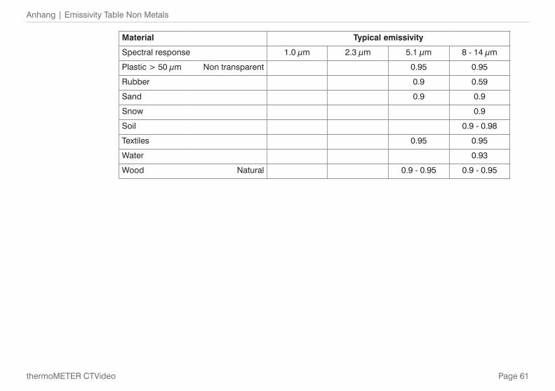
Material Typical emissivity
Spectral response 1.0 μm 2.3 μm 5.1 μm 8 - 14 μm
Plastic > 50 μm Non transparent 0.95 0.95
Rubber 0.9 0.59
Sand 0.9 0.9
Snow 0.9
Soil 0.9 - 0.98
Textiles 0.95 0.95
Water 0.93
Wood Natural 0.9 - 0.95 0.9 - 0.95
Page 62
Anhang | Smart Averaging
thermoMETER CTVideo
A 5 Smart Averaging
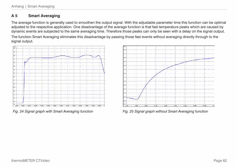
The average function is generally used to smoothen the output signal. With the adjustable parameter time this function can be optimal adjusted to the respective application. One disadvantage of the average function is that fast temperature peaks which are caused by dynamic events are subjected to the same averaging time. Therefore those peaks can only be seen with a delay on the signal output.
The function Smart Averaging eliminates this disadvantage by passing those fast events without averaging directly through to the signal output.
Fig. 24 Signal graph with Smart Averaging function Fig. 25 Signal graph without Smart Averaging function

MICRO-EPSILON MESSTECHNIK GmbH & Co. KG
Königbacher Str. 15 · 94496 Ortenburg / Germany
Tel. +49 (0) 8542 / 168-0 · Fax +49 (0) 8542 / 168-90
[email protected] · www.micro-epsilon.com
X9751322-B011045HDR
*X9751322-B01*
MICRO-EPSILON MESSTECHNIK