Embed Size (px)
Citation preview
D147-01-880Issue F
Instruction Manual
Wide Range Gauge
Description Item Number
WRG-S-NW25 D147-01-000
WRG-SL-NW25 D147-11-000
WRG-D-NW25 D147-02-000
WRG-S-DN40CF D147-03-000
© Edwards Limited 2007. All rights reserved. Page iEdwards and the Edwards logo are trademarks of Edwards Limited.
ContentsD147-01-880 Issue F
Contents
Section Page
1 Introduction ....................................................................................... 1
1.1 Scope and definitions ................................................................................................... 11.2 Description ................................................................................................................ 11.3 Gas dependency .......................................................................................................... 2
2 Technical data .................................................................................... 5
2.1 Mechanical data .......................................................................................................... 52.2 Performance, operating and storage conditions .................................................................... 52.3 Electrical data ............................................................................................................ 52.4 Materials exposed to vacuum .......................................................................................... 6
3 Installation ....................................................................................... 11
3.1 Unpack and inspect .....................................................................................................113.2 Fit the WRG to the vacuum system ..................................................................................113.3 Electrical connections ..................................................................................................113.3.1 Connect to Edwards controllers or AGD display ....................................................................113.3.2 Connect to your own supply and control equipment ..............................................................11
4 Operation ........................................................................................ 13
4.1 Safety .....................................................................................................................134.2 Pressure measurement .................................................................................................144.3 Atmosphere adjustment ...............................................................................................144.4 Vacuum adjustment ....................................................................................................154.5 Set-point .................................................................................................................154.6 Error monitoring ........................................................................................................16
5 Maintenance ..................................................................................... 17
5.1 Introduction .............................................................................................................175.2 Replace the body tube .................................................................................................175.3 Replace the electrode and pirani assemblies ......................................................................185.4 Replace the electronics and magnet housing ......................................................................195.5 Clean the internal components .......................................................................................19
6 Storage and disposal ........................................................................... 21
6.1 Storage ...................................................................................................................216.2 Disposal ...................................................................................................................21
7 Service, spares and accessories .............................................................. 23
7.1 Introduction .............................................................................................................237.2 Service ....................................................................................................................237.3 Spares .....................................................................................................................237.4 Accessories ...............................................................................................................24
For return of equipment, complete the HS Forms at the end of this manual.
dcs/
7823
/12/
07
D147-01-880 Issue F
Page ii © Edwards Limited 2007. All rights reserved.Edwards and the Edwards logo are trademarks of Edwards Limited.
Contents
Illustrations
Figure Page1 General view of the WRG-S and -SL ................................................................................... 22 General view of the WRG-D ............................................................................................ 33 Dimensions (mm) of the WRG-S-NW25 and WRG-SL-NW25 ........................................................ 74 Dimensions (mm) of the WRG-D-NW25 ............................................................................... 85 Dimensions (mm) of the WRG-S-DN40CF ............................................................................. 96 Schematic diagram of typical electrical connections for the WRG .............................................127 Pressure-voltage characteristic of the WRG ........................................................................148 Refitting the body tube assembly ....................................................................................189 Exploded view of the body tube assembly ..........................................................................20
Tables
Table Page1 Pin identification .......................................................................................................12
Trademark credits
Scotchbrite™ is a trademark of 3M Global Trading, Inc.
© Edwards Limited 2007. All rights reserved. Page 1Edwards and the Edwards logo are trademarks of Edwards Limited.
IntroductionD147-01-880 Issue F
1 Introduction1.1 Scope and definitions
This manual provides installation, operation and maintenance instructions for the Edwards WRG (Wide Range Gauge). You must use the WRG as specified in this manual.
Read this manual before you install and operate the WRG. Important safety information is highlighted as WARNING and CAUTION instructions; you must obey these instructions. The use of WARNINGS and CAUTIONS is defined below.
CAUTIONCautions are given where failure to observe the instruction could result in damage to the equipment, associated equipment or process.
The units used throughout the manual conform to the SI international system of units of measurement.
The following symbol is on the Wide Range Gauge:
1.2 Description
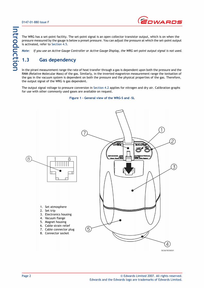
The Wide Range Gauge, shown in Figure 1, is a combined inverted magnetron and pirani gauge in a single compact unit.
The WRG incorporates a unique striking mechanism consisting of a small incandescent filament mounted inside the magnetron tube. This filament is automatically ignited providing enough emission electrons to initiate the discharge.
The WRG incorporates an intelligent microprocessor based control system which is used to control the various features such as:
Automatic control of the magnetron HT voltage during the ignition of the gauge.
Reduction of the HT voltage after ignition to enhance the life time of the gauge.
Automatic adjustment of the pirani vacuum reading.
Provision of an error monitoring feature which will help identify the exact cause of failure.
Simple adjustment of the set-point trip level.
Three versions of the Wide Range Gauge are available: the ‘S’, ‘SL’ and the ‘D’ gauges. The ‘S’ and ‘SL’ versions have an FCC68 connector socket while the ‘D’ version has a 9 way D-type socket. The ‘SL’ gauges have a very low external magnetic field and are suitable for use with sensitive analytical instruments. The ‘S’ version is available with either a NW25 or DN40CF flange.
The WRG is compatible with the AGC range (Active Gauge Controllers) and with the appropriate versions of the AGD (Active Gauge Display). Alternatively, an independent power supply can be used for the WRG and the output signal can be read with a voltmeter or an analogue-to-digital converter.
WARNING
Warnings are given where failure to observe the instruction could result in injury or death to people.
From August 2005, Edwards will offer European customers a recycling service.
D147-01-880 Issue F
Page 2 © Edwards Limited 2007. All rights reserved.Edwards and the Edwards logo are trademarks of Edwards Limited.
Introduction
The WRG has a set-point facility. The set-point signal is an open collector transistor output, which is on when the pressure measured by the gauge is below a preset pressure. You can adjust the pressure at which the set-point output is activated, refer to Section 4.5.
Note: If you use an Active Gauge Controller or Active Gauge Display, the WRG set-point output signal is not used.
1.3 Gas dependency
In the pirani measurement range the rate of heat transfer through a gas is dependent upon both the pressure and the RMM (Relative Molecular Mass) of the gas. Similarly, in the inverted magnetron measurement range the ionisation of the gas in the vacuum system is dependent on both the pressure and the physical properties of the gas. Therefore, the output signal of the WRG is gas dependent.
The output signal voltage to pressure conversion in Section 4.2 applies for nitrogen and dry air. Calibration graphs for use with other commonly used gases are available on request.
Figure 1 - General view of the WRG-S and -SL
1. Set atmosphere2. Set trip3. Electronics housing4. Vacuum flange5. Magnet housing6. Cable strain relief7. Cable connector plug8. Connector socket
© Edwards Limited 2007. All rights reserved. Page 3Edwards and the Edwards logo are trademarks of Edwards Limited.
IntroductionD147-01-880 Issue F
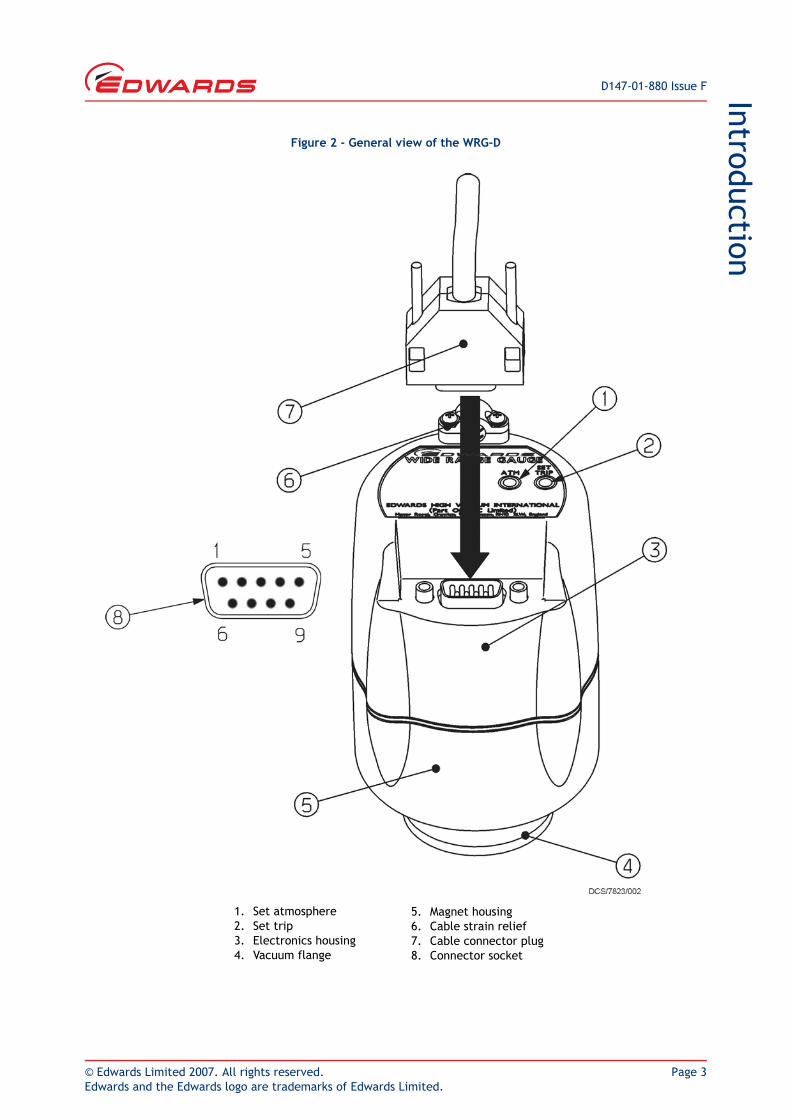
Figure 2 - General view of the WRG-D
1. Set atmosphere2. Set trip3. Electronics housing4. Vacuum flange
5. Magnet housing6. Cable strain relief7. Cable connector plug8. Connector socket

D147-01-880 Issue F
Page 4 © Edwards Limited 2007. All rights reserved.Edwards and the Edwards logo are trademarks of Edwards Limited.
This page has been intentionally left blank.

© Edwards Limited 2007. All rights reserved. Page 5Edwards and the Edwards logo are trademarks of Edwards Limited.
Technical dataD147-01-880 Issue F
2 Technical data2.1 Mechanical data
2.2 Performance, operating and storage conditions
2.3 Electrical data
Dimensions See Figure 3, 4 and 5
Mass
WRG-S-NW25 750 g
WRG-D-NW25 750 g
WRG-SL-NW25 800 g
WRG-S-DN40CF 1000 g
Volume of gauge tube 26 cm3
Enclosure rating
WRG-S-NW25 IP40
WRG-SL-NW25 IP40
WRG-S-DN40CF IP40
WRG-D-NW25 IP44 (provided that the gauge is mounted vertically with the vacuum flange at the bottom)
Ambient temperature
Operation 5 to 60 °C
Storage 0 to 70 °C
Ambient humidity (operation) max 90% RH (non-condensing) up to 31 °C max 70% RH (non-condensing) above 31 °C
Maximum internal pressure 6 bar absolute (5 bar gauge)
Maximum operating altitude 2000 m
Pressure measurement range 100 to 10-9 mbar (indicates pressures up to 1000 mbar at reduced accuracy)
Pollution category IEC1010 Category 2
Electrical supply
Voltage +14.5 to +36 V d.c.
Max voltage ripple 1 V peak to peak
Max source resistance 50 Ω
Maximum power consumption 2 W
Electrical connector
WRG-S-NW25 FCC68/RJ45 type, 8-way
WRG-SL-NW25 FCC68/RJ45 type, 8-way
WRG-S-DN40CF FCC68/RJ45 type, 8-way
WRG-D-NW25 9 way D-type male

D147-01-880 Issue F
Page 6 © Edwards Limited 2007. All rights reserved.Edwards and the Edwards logo are trademarks of Edwards Limited.
Technical data
2.4 Materials exposed to vacuum
Stainless steel (AISI 304, 316, 321, 347)
Fluoroelastomer
Soda lime glass
Tungsten
Trace of Nickel and Nickel iron
Pressure output signal
Range 2 - 10 V d.c.
Error range < 1.5 V d.c. or > 10.15 V d.c.
Impedance 0.1 Ω
Min load impedance 10 kΩ
Max current source 1 mA
Set-point output external load rating 40 V d.c., 100 mA max
Set-point trip level
Range 1.8 to 10.2 V
Hysteresis 330 mV
Back EMF suppression diode *
Min. surge rating 1 A
Min. reverse voltage rating 100 V
Atmosphere calibration input
Control sense Active low
Active level < 1.5 V
Control impedance 100 kΩ pull-up to positive supply
Gauge identification resistance 75 kΩ ± 2%* Required when you use an external d.c. relay connected to the set-point output.
© Edwards Limited 2007. All rights reserved. Page 7Edwards and the Edwards logo are trademarks of Edwards Limited.
Technical dataD147-01-880 Issue F
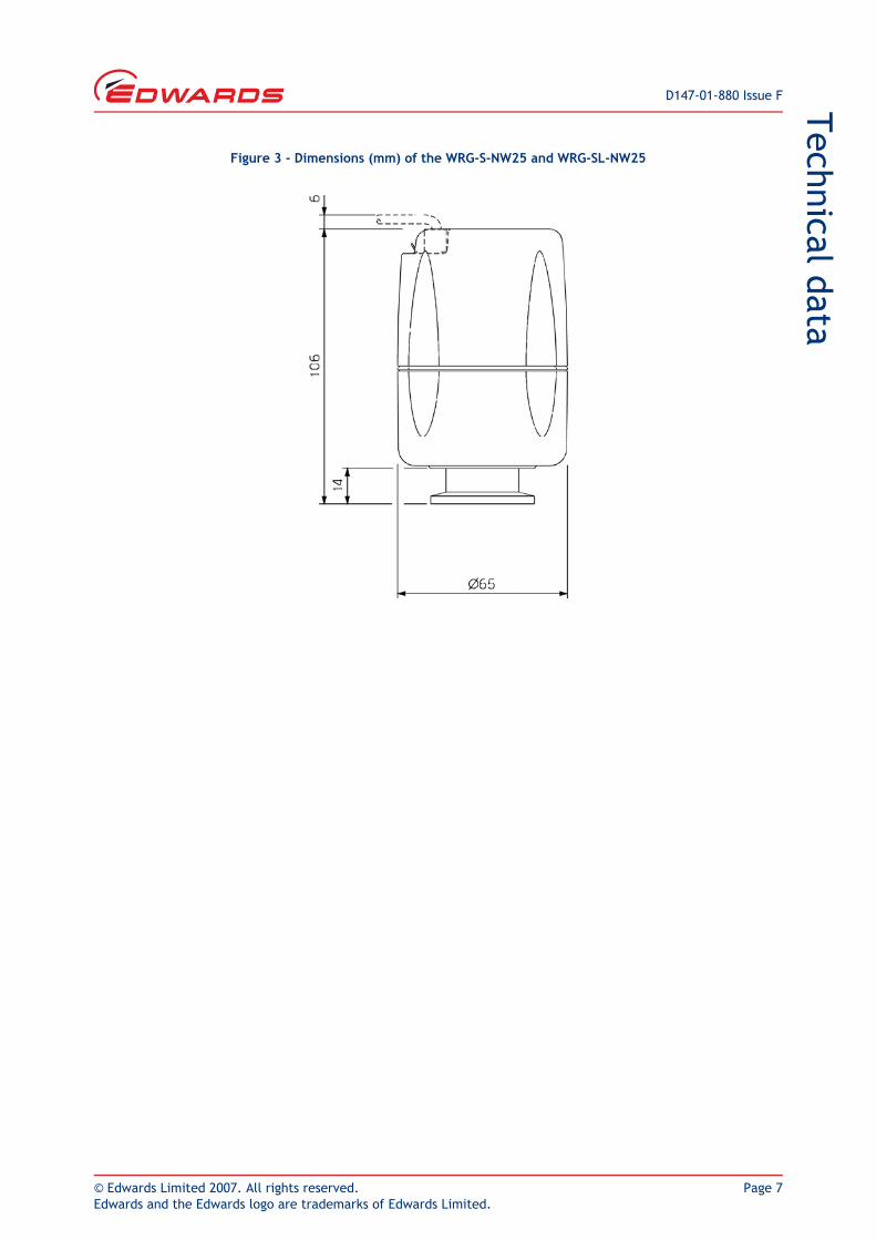
Figure 3 - Dimensions (mm) of the WRG-S-NW25 and WRG-SL-NW25
D147-01-880 Issue F
Page 8 © Edwards Limited 2007. All rights reserved.Edwards and the Edwards logo are trademarks of Edwards Limited.
Technical data
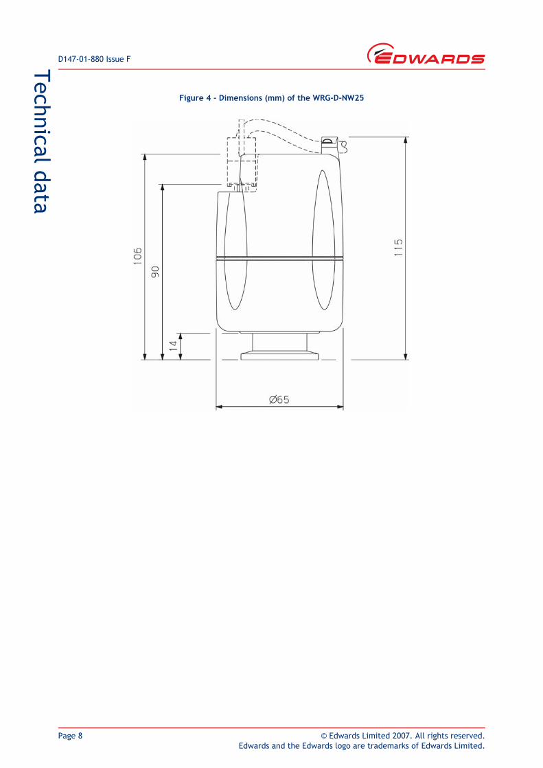
Figure 4 - Dimensions (mm) of the WRG-D-NW25
© Edwards Limited 2007. All rights reserved. Page 9Edwards and the Edwards logo are trademarks of Edwards Limited.
Technical dataD147-01-880 Issue F
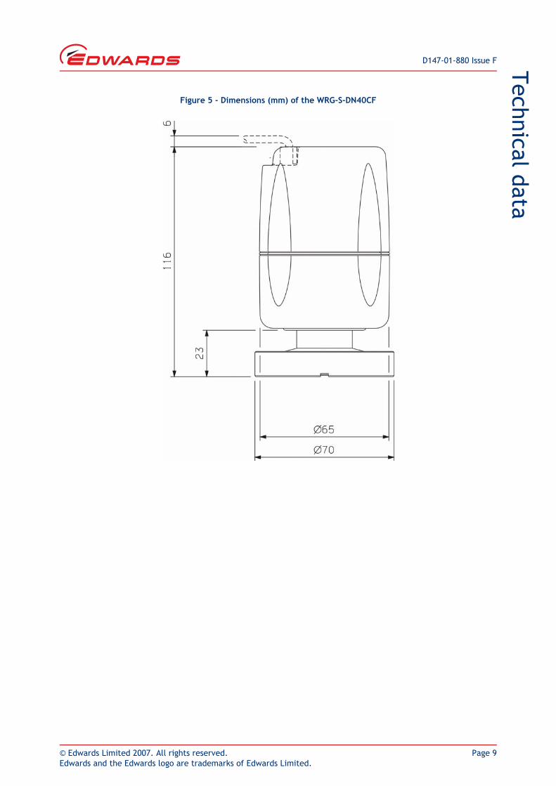
Figure 5 - Dimensions (mm) of the WRG-S-DN40CF

D147-01-880 Issue F
Page 10 © Edwards Limited 2007. All rights reserved.Edwards and the Edwards logo are trademarks of Edwards Limited.
This page has been intentionally left blank.
© Edwards Limited 2007. All rights reserved. Page 11Edwards and the Edwards logo are trademarks of Edwards Limited.
InstallationD147-01-880 Issue F
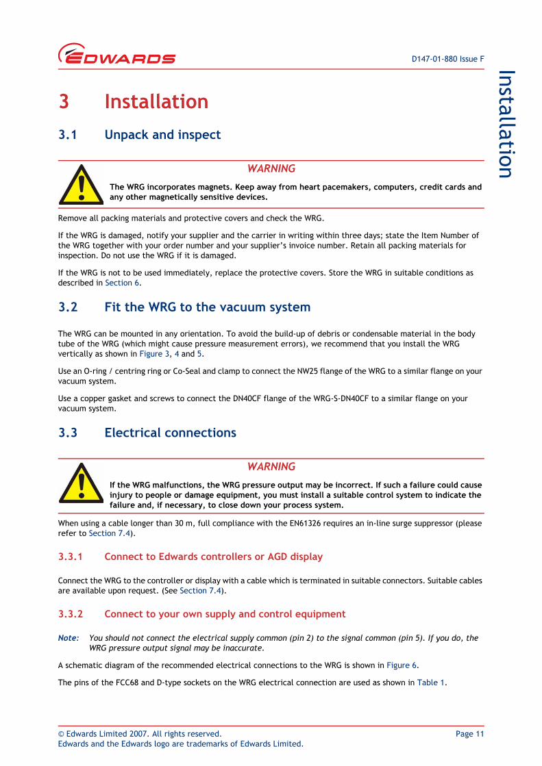
3 Installation3.1 Unpack and inspect
Remove all packing materials and protective covers and check the WRG.
If the WRG is damaged, notify your supplier and the carrier in writing within three days; state the Item Number of the WRG together with your order number and your supplier’s invoice number. Retain all packing materials for inspection. Do not use the WRG if it is damaged.
If the WRG is not to be used immediately, replace the protective covers. Store the WRG in suitable conditions as described in Section 6.
3.2 Fit the WRG to the vacuum system
The WRG can be mounted in any orientation. To avoid the build-up of debris or condensable material in the body tube of the WRG (which might cause pressure measurement errors), we recommend that you install the WRG vertically as shown in Figure 3, 4 and 5.
Use an O-ring / centring ring or Co-Seal and clamp to connect the NW25 flange of the WRG to a similar flange on your vacuum system.
Use a copper gasket and screws to connect the DN40CF flange of the WRG-S-DN40CF to a similar flange on your vacuum system.
3.3 Electrical connections
When using a cable longer than 30 m, full compliance with the EN61326 requires an in-line surge suppressor (please refer to Section 7.4).
3.3.1 Connect to Edwards controllers or AGD display
Connect the WRG to the controller or display with a cable which is terminated in suitable connectors. Suitable cables are available upon request. (See Section 7.4).
3.3.2 Connect to your own supply and control equipment
Note: You should not connect the electrical supply common (pin 2) to the signal common (pin 5). If you do, the WRG pressure output signal may be inaccurate.
A schematic diagram of the recommended electrical connections to the WRG is shown in Figure 6.
The pins of the FCC68 and D-type sockets on the WRG electrical connection are used as shown in Table 1.
WARNING
The WRG incorporates magnets. Keep away from heart pacemakers, computers, credit cards and any other magnetically sensitive devices.
WARNING
If the WRG malfunctions, the WRG pressure output may be incorrect. If such a failure could cause injury to people or damage equipment, you must install a suitable control system to indicate the failure and, if necessary, to close down your process system.
D147-01-880 Issue F
Page 12 © Edwards Limited 2007. All rights reserved.Edwards and the Edwards logo are trademarks of Edwards Limited.
Installation
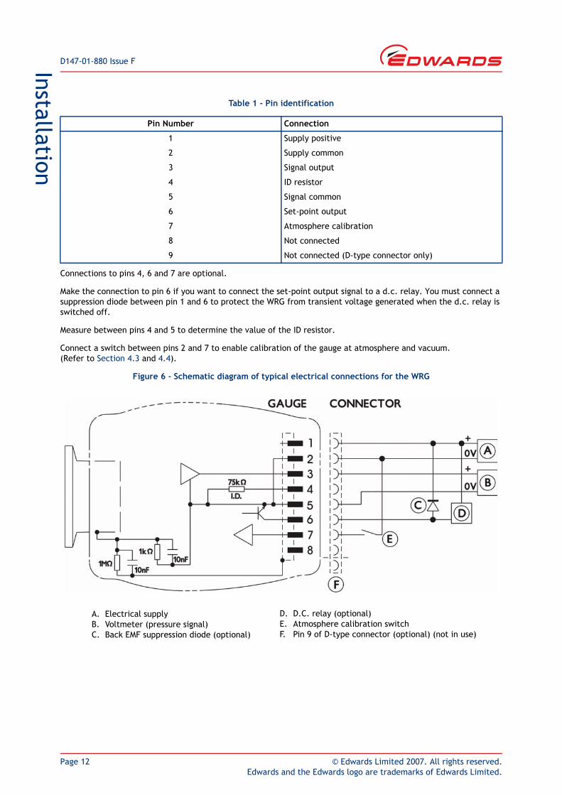
Connections to pins 4, 6 and 7 are optional.
Make the connection to pin 6 if you want to connect the set-point output signal to a d.c. relay. You must connect a suppression diode between pin 1 and 6 to protect the WRG from transient voltage generated when the d.c. relay is switched off.
Measure between pins 4 and 5 to determine the value of the ID resistor.
Connect a switch between pins 2 and 7 to enable calibration of the gauge at atmosphere and vacuum. (Refer to Section 4.3 and 4.4).
Figure 6 - Schematic diagram of typical electrical connections for the WRG
Table 1 - Pin identification
Pin Number Connection
1 Supply positive
2 Supply common
3 Signal output
4 ID resistor
5 Signal common
6 Set-point output
7 Atmosphere calibration
8 Not connected
9 Not connected (D-type connector only)
A. Electrical supplyB. Voltmeter (pressure signal)C. Back EMF suppression diode (optional)
D. D.C. relay (optional)E. Atmosphere calibration switchF. Pin 9 of D-type connector (optional) (not in use)
© Edwards Limited 2007. All rights reserved. Page 13Edwards and the Edwards logo are trademarks of Edwards Limited.
Operation
D147-01-880 Issue F
4 Operation4.1 Safety
CAUTIONThe WRG has a magnet which may affect sensitive devices such as floppy disks. The effect is reduced on the -SL version.
WARNING
Do not use the WRG to measure the pressure of explosive or flammable gases or mixtures.
WARNING
Never operate the WRG when it is disconnected from the vacuum system or when there are explosive or flammable gases in the surrounding atmosphere or the vacuum system. High voltages (up to 3 kV) are generated inside the body tube of the WRG; these could cause injury to people or could be a source of ignition.
WARNING
Do not disconnect the electronics and magnet housing from the body tube when the body tube is connected to the vacuum system. If there is a plasma discharge in the vacuum system near the body tube, the body tube can become electrically charged.
WARNING
When the pressure of gases of high molecular weight are measured, the pressure indicated can be below the true pressure. Ensure that the WRG is not over-pressurised when you use heavy gases.
WARNING
Use the gauge only for its intended purpose as described in this instruction manual.
WARNING
The WRG incorporates magnets. Keep away from heart pacemakers, computers, credit cards and any other magnetically sensitive devices.

D147-01-880 Issue F
Page 14 © Edwards Limited 2007. All rights reserved.Edwards and the Edwards logo are trademarks of Edwards Limited.
Operation
4.2 Pressure measurement
If you connect the WRG to an Edwards AGC controller or AGD display, the pressure measured by the WRG is shown on the display.
If you connect the signal output of the WRG to a voltmeter, convert the measured voltage to the corresponding pressure value using the following equation:
where V is the measured voltage. For example, if the measured voltage V = 4, then pressure P = 10-6 mbar. Refer also to Figure 7.
4.3 Atmosphere adjustment
Use the “ATM” switch (see Figure 1 and 2, item 3) or pin 7 and 2 to set the reading at atmosphere.
Switch on the power supply to the WRG and allow it to operate at atmospheric pressure for at least 10 minutes.
With the vacuum system at atmospheric pressure, press the “ATM” switch with an appropriate tool. The output of the gauge will be automatically adjusted to read atmosphere.
Figure 7 - Pressure-voltage characteristic of the WRG
P =10(1.5 V-12) mbar
= 10(1.5 V-10) Pascal
= 10(1.5 V-12.125) torr

© Edwards Limited 2007. All rights reserved. Page 15Edwards and the Edwards logo are trademarks of Edwards Limited.
Operation
D147-01-880 Issue F
4.4 Vacuum adjustment
The WRG will perform the pirani sensor vacuum setting automatically every time the WRG is pumped down to a pressure lower than 10-4 mbar. Therefore a manual setting of vacuum is not required unless the pirani tube is replaced.
If the gauge fails to indicate pressure of < 10-3 mbar, then a manual vacuum setting is required. To perform this operation, follow the procedure below.
Reduce the system pressure to 10-5 mbar or below and wait for 1 minute. Press and release the “ATM” switch and wait for approximately 30 seconds until the adjustment is completed. Manual adjustment of the vacuum reading is recommended when replacing the pirani tube or after a long period of storage.
If an operator has tried to set the atmosphere or vacuum reading while the actual pressure is between 10-2 and 102 mbar, an error voltage of 1 V will be displayed indicating a pirani failure. See Section 4.6.
4.5 Set-point
Note: The set-point is not used if you connect the WRG to an Edwards Active Gauge Controller or Active Gauge Display.
To read the voltage at which the set-point output signal is activated, press the set trip switch (see Figure 1 and 2) with an appropriate tool. The output of the gauge will indicate the set trip level for 3 seconds after which the output will read the normal voltage output.
To adjust the voltage at which the set-point output signal is activated, press the set trip switch and hold it down for more than 3 seconds. The set-point voltage will start scrolling upwards. Remove pressure from the switch as soon as you reach the required trip voltage. To make a finer adjustment, remove pressure from the set trip switch and immediately depress the switch as many times as required. Each depression will increase the set trip voltage by about 10 mV. Refer to Section 4.2 to determine the operating voltage which corresponds to a given pressure.
The WRG has an error monitoring facility, which ensures that the set-point output signal is off:
when the gauge is switched off
for 2 seconds immediately after the WRG is switched on
when the pressure output signal is out of range
when an error voltage is detected, see Section 4.6
If required, you can adjust the set-point operating voltage to < 1.9 V. This ensures that the set-point output is permanently off.
If required, you can use the set-point output signal to indicate when the gauge is operating correctly. Adjust the set-point operating voltage to > 10.15 V. The set-point output will then be on if the gauge is operating normally, and off if an error condition is detected.
Note: If you adjust the set-point operating voltage to > 9.7 V, the hysteresis voltage will be > 10 V and the set-point output signal may not switch off when the pressure rises. If so, the set-point output signal will switch off only when the gauge is switched off.
D147-01-880 Issue F
Page 16 © Edwards Limited 2007. All rights reserved.Edwards and the Edwards logo are trademarks of Edwards Limited.
Operation
4.6 Error monitoring
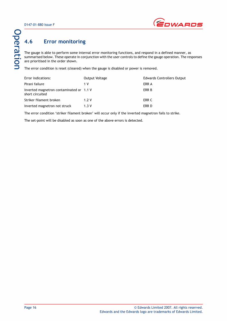
The gauge is able to perform some internal error monitoring functions, and respond in a defined manner, as summarised below. These operate in conjunction with the user controls to define the gauge operation. The responses are prioritised in the order shown.
The error condition is reset (cleared) when the gauge is disabled or power is removed.
The error condition ‘striker filament broken’ will occur only if the inverted magnetron fails to strike.
The set-point will be disabled as soon as one of the above errors is detected.
Error indications: Output Voltage Edwards Controllers Output
Pirani failure 1 V ERR A
Inverted magnetron contaminated or short circuited
1.1 V ERR B
Striker filament broken 1.2 V ERR C
Inverted magnetron not struck 1.3 V ERR D

© Edwards Limited 2007. All rights reserved. Page 17Edwards and the Edwards logo are trademarks of Edwards Limited.
Maintenance
D147-01-880 Issue F
5 Maintenance5.1 Introduction
The internal components of the WRG are shown in Figure 8. The WRG is designed so that you can clean these components, or use the spares listed in Section 7.3 to replace these components. Refer to the following sections for details of maintenance procedures, which you should perform when necessary.
5.2 Replace the body tube
Refer to Figure 8 and use the following procedures to replace the body tube.
To remove the body tube assembly:
Switch off the WRG electrical supply and ensure that the vacuum system is at atmospheric pressure.
Disconnect the cable connector plug (Figure 1 and 2, item 7) and remove the WRG from the vacuum system.
Hold the magnet housing firmly and pull the body tube assembly to remove.
To refit the body tube assembly:
Insert the body tube assembly into the magnet housing and then rotate it while maintaining gentle pressure until the tube assembly locates. Push fully home until the locking spring snaps into position.
Refit the gauge to the vacuum system as described in Section 3.2 and reconnect the electrical supply.
WARNING
Do not disconnect the electronics and magnet housing from the body tube when the body tube is connected to the vacuum system. If there is a plasma discharge in the vacuum system near the body tube, the pins of the anode assembly can become electrically charged.
WARNING
Disconnect the cable from the WRG before you remove the WRG from the vacuum system. High voltages are generated inside the WRG.
D147-01-880 Issue F
Page 18 © Edwards Limited 2007. All rights reserved.Edwards and the Edwards logo are trademarks of Edwards Limited.
Maintenance
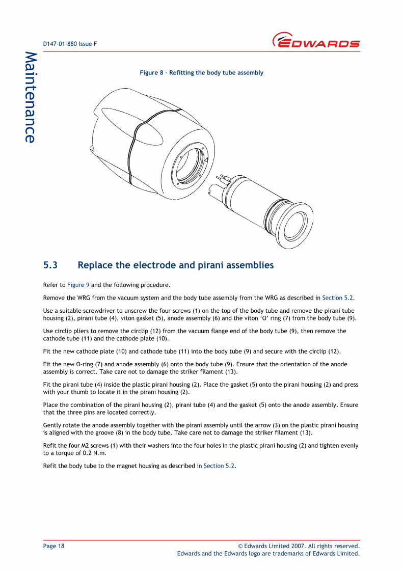
Figure 8 - Refitting the body tube assembly
5.3 Replace the electrode and pirani assemblies
Refer to Figure 9 and the following procedure.
Remove the WRG from the vacuum system and the body tube assembly from the WRG as described in Section 5.2.
Use a suitable screwdriver to unscrew the four screws (1) on the top of the body tube and remove the pirani tube housing (2), pirani tube (4), viton gasket (5), anode assembly (6) and the viton ‘O’ ring (7) from the body tube (9).
Use circlip pliers to remove the circlip (12) from the vacuum flange end of the body tube (9), then remove the cathode tube (11) and the cathode plate (10).
Fit the new cathode plate (10) and cathode tube (11) into the body tube (9) and secure with the circlip (12).
Fit the new O-ring (7) and anode assembly (6) onto the body tube (9). Ensure that the orientation of the anode assembly is correct. Take care not to damage the striker filament (13).
Fit the pirani tube (4) inside the plastic pirani housing (2). Place the gasket (5) onto the pirani housing (2) and press with your thumb to locate it in the pirani housing (2).
Place the combination of the pirani housing (2), pirani tube (4) and the gasket (5) onto the anode assembly. Ensure that the three pins are located correctly.
Gently rotate the anode assembly together with the pirani assembly until the arrow (3) on the plastic pirani housing is aligned with the groove (8) in the body tube. Take care not to damage the striker filament (13).
Refit the four M2 screws (1) with their washers into the four holes in the plastic pirani housing (2) and tighten evenly to a torque of 0.2 N.m.
Refit the body tube to the magnet housing as described in Section 5.2.
© Edwards Limited 2007. All rights reserved. Page 19Edwards and the Edwards logo are trademarks of Edwards Limited.
Maintenance
D147-01-880 Issue F
5.4 Replace the electronics and magnet housing
The magnet housing and end-cap contain the WRG control electronics. Replace the complete unit as described below.
Remove the WRG from the vacuum system and the body tube assembly as described in Section 5.2.
Dispose of the old electronics and magnet housing (refer to Section 6.2).
Fit the body tube to the new electronics and magnet housing as described in Section 5.2. Refit the WRG to the vacuum system as described in Section 3.2.
5.5 Clean the internal components
Refer to Figure 9 in the following procedure.
Remove the internal components from the magnet housing as described in Section 5.3.
Clean the pirani tube (4) in alcohol for about 5 minutes (using an ultrasonic tank if available). Place the pirani tube (4) with the opening end facing downward on a piece of clean tissue and leave it to dry.
Use an abrasive material (e. g. Scotchbrite™) to clean the anode assembly (6). Extra care is required when cleaning the area around the striker filament (13).
Clean the anode assembly (6) in alcohol for about 5 minutes (using an ultrasonic tank if available). Place the anode assembly (6) on a piece of clean tissue and leave it to dry.
Degrease the cathode plate (10), cathode tube (11) and body tube (9) in a suitable degreasing agent. Thoroughly soak them in a suitable laboratory detergent. Rinse in clean water to remove the detergent and then in methanol to remove all of the water, then thoroughly dry the components.
Refit the components in the electronics and magnet housing as described in Section 5.2.

D147-01-880 Issue F
Page 20 © Edwards Limited 2007. All rights reserved.Edwards and the Edwards logo are trademarks of Edwards Limited.
Maintenance
Figure 9 - Exploded view of the body tube assembly
1. M2 screws and washers2. Pirani housing3. Alignment arrow4. Pirani tube5. Gasket6. Anode assembly7. O-ring
8. Alignment groove9. Body tube10. Cathode plate11. Cathode tube12. Circlip13. Strike filament
© Edwards Limited 2007. All rights reserved. Page 21Edwards and the Edwards logo are trademarks of Edwards Limited.
Storage and disposalD147-01-880 Issue F
6 Storage and disposal6.1 Storage
Return the WRG to its protective packaging and store the WRG in clean dry conditions until required for use. Do not exceed the storage temperature conditions specified in Section 2.
When required for use, prepare and install the WRG as described in Section 3.
6.2 Disposal
Dispose of the WRG and any components safely in accordance with all local and national safety and environmental requirements.
Alternatively, you may be able to recycle the WRG and/or cables; contact Edwards or your supplier for advice (also see below).
The WRG and associated cables are within the scope of the European Directive on Waste Electrical and Electronic Equipment, 2002/96/EC. From August 2005, Edwards will offer European customers a recycling service for theWRG/cables at the end of the product’s life. Contact Edwards for advice on how to return the WRG/cables for recycling.
Particular care must be taken if the WRG has been contaminated with dangerous process substances or if the WRG has been overheated or has been in a fire. Fluoroelastomers are used in the WRG; these are safe in normal use, but can decompose into dangerous breakdown products if heated to 260 °C and above.

D147-01-880 Issue F
Page 22 © Edwards Limited 2007. All rights reserved.Edwards and the Edwards logo are trademarks of Edwards Limited.
This page has been intentionally left blank.
© Edwards Limited 2007. All rights reserved. Page 23Edwards and the Edwards logo are trademarks of Edwards Limited.
Service, spares and accessoriesD147-01-880 Issue F
7 Service, spares and accessories7.1 Introduction
Edwards products, spares and accessories are available from Edwards companies in Belgium, Brazil, Canada, France, Germany, Hong Kong, Italy, Japan, Korea, Switzerland, United Kingdom, U.S.A and a world-wide network of distributors. The majority of these centres employ Service Engineers who have undergone comprehensive Edwards training courses.
When you maintain this Edwards product, we recommend you use only Edwards maintenance and service kits.
Order spare parts and accessories from your nearest Edwards company or distributor. When you order, please state for each part required:
Model and Item Number of your equipment
Serial number (if any)
Item Number and description of the part.
7.2 Service
Edwards products are supported by a world-wide network of Edwards Service Centres. Each Service Centre offers a wide range of options including: equipment decontamination; service exchange; repair; rebuild and testing to factory specifications. Equipment which has been serviced, repaired or built is returned with a full warranty.
Your local Service Centre can also provide Edwards engineers to support on-site maintenance, service or repair of your equipment.
For more information about service options, contact your nearest Service Centre or other Edwards company.
7.3 Spares
Spares Item Number
Electronics and magnet housing
WRG-S-NW25 D147-01-800
WRG-SL-NW25 D147-11-800
WRG-D-NW25 D147-02-800
Body tube assembly NW25 D147-01-801
Body tube assembly DN40CF D147-03-801
Electrode assembly kit *
* The electrode assembly kit contains one each of the following components: cathode plate, cathode tube, anode assembly, O-ring, plastic pirani housing, circlip, gasket and 4 screws and washers.
D147-01-802
Pirani tube replacement kit †
† The pirani tube replacement kit contains one each of the following components: pirani tube assembly, pirani housing, gasket and 4 screws and washers.
D147-01-803
Full body tube service kit ‡
‡ The full body tube service kit contains one each of the following components: cathode plate, cathode tube, anode assembly, O-ring, pirani tube assembly, plastic pirani housing, circlip, gasket and 4 screws and washers.
D147-01-804
D147-01-880 Issue F
Page 24 © Edwards Limited 2007. All rights reserved.Edwards and the Edwards logo are trademarks of Edwards Limited.
Service, spares and accessories
7.4 Accessories
The cables suitable for use with the WRG are as follows. These cables are supplied with 8-way male electrical connectors on both ends.
Cable length Item Number
0.5 m 18 inches D400-01-005
1 m 3 feet D400-01-010
3 m 10 feet D400-01-030
5 m 15 feet D400-01-050
10 m 30 feet D400-01-100
15 m 50 feet D400-01-150
25 m 80 feet D400-01-250
50 m 150 feet D400-01-500
100 m 325 feet D400-01-999
9-way D type to FCC68 adapter D400-03-100
Surge suppressor D400-06-000