Embed Size (px)
Citation preview
WARRANTYGreat Planes® Model Manufacturing Co. guarantees this kit to be free from defects in both material and workmanship at the date of purchase.This warranty does not cover any component parts damaged by use or modification. In no case shall Great Planes’ liability exceed theoriginal cost of the purchased kit. Further, Great Planes reserves the right to change or modify this warranty without notice.
In that Great Planes has no control over the final assembly or material used for final assembly, no liability shall be assumed nor accepted forany damage resulting from the use by the user of the final user-assembled product. By the act of using the user-assembled product, the useraccepts all resulting liability.
If the buyer is not prepared to accept the liability associated with the use of this product, the buyer is advised to return this kitimmediately in new and unused condition to the place of purchase.
READ THROUGH THIS MANUAL BEFORE STARTINGCONSTRUCTION. IT CONTAINS IMPORTANTINSTRUCTIONS AND WARNINGS CONCERNINGTHE ASSEMBLY AND USE OF THIS MODEL.
GPMZ0216 for GPMA1305 V1.0 Entire Contents © Copyright 2002
1610 Interstate Drive Champaign, IL 61822(217) 398-8970, Ext. 2
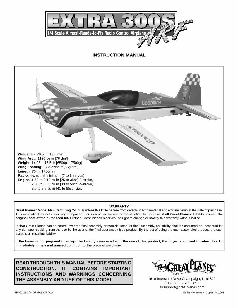
INSTRUCTION MANUAL
Wingspan: 78.5 in [1995mm] Wing Area: 1180 sq in [76 dm2] Weight: 14.25 – 16.5 lb [6500g – 7500g] Wing Loading: 27.8 oz/sq ft [85g/dm2] Length: 70 in [1780mm] Radio: 4-channel minimum (7 to 8 servos)Engine: 1.60 to 2.10 cu in [25 to 35cc] 2-stroke,
2.00 to 3.00 cu in [33 to 50cc] 4-stroke,2.5 to 3.8 cu in [41 to 65cc] Gas
INTRODUCTION................................................................2IMAA ..................................................................................2SAFETY PRECAUTIONS ..................................................3DECISIONS YOU MUST MAKE BEFOREBEGINNING TO BUILD .....................................................3
Radio Equipment .........................................................4Engine Recommendations...........................................4
ADDITIONAL ITEMS REQUIRED .....................................4Hardware & Accessories .............................................4Adhesives & Building Supplies ....................................5Optional Supplies & Tools............................................5
IMPORTANT BUILDING NOTES.......................................5METRIC/INCH RULER ......................................................6ORDERING REPLACEMENT PARTS...............................6KIT CONTENTS.................................................................7BUILDING INSTRUCTIONS ..............................................8
Preparations.................................................................8ASSEMBLE THE WING.....................................................8
Hook up the Ailerons ...................................................8Mount the Wing on the Fuselage...............................11
ASSEMBLE THE FUSELAGE.........................................11Install the Servo Tray .................................................11Engine Mounting Preparations ..................................12Install the Engine .......................................................13Install a Glow Engine.................................................13Install a Gas Engine ..................................................15Install the Cowl ..........................................................18Install the Tail Surfaces ..............................................19Installing the Landing Gear........................................23Finish the Radio Installation ......................................26Finish the Cockpit ......................................................27Apply the Decals........................................................27
GET THE MODEL READY TO FLY..................................27Check the Control Directions .....................................27Set the Control Throws ..............................................28Balance the Model (C.G.) ..........................................28Balance the Model Laterally ......................................29
PREFLIGHT .....................................................................29Identify Your Model.....................................................29Charge the Batteries..................................................29Balance the Propellers...............................................29Ground Check............................................................29Range Check .............................................................29
ENGINE SAFETY PRECAUTIONS .................................30AMA SAFETY CODE (excerpt) ......................................30IMAA SAFETY CODE (excerpt) .....................................30CHECK LIST....................................................................32FLYING.............................................................................32
Fuel Mixture Adjustments ..........................................32Takeoff .......................................................................33Flight ..........................................................................33Landing ......................................................................33Performance Settings ................................................333D Control Throws .....................................................343D Servo Arms ..........................................................34Servos........................................................................34
APPENDIX .......................................................................35FLIGHT TRIMMING..........................................................38TAIL WHEEL PUSHROD PATTERN................................39ENGINE MOUNT TEMPLATE..........................................39
The Great Planes 1/4-Scale Patty Wagstaff Extra 300SARFis a versatile airplane designed for giant-scale aerobatics. TheExtra 300S ARF is capable of wild, 3D aerobatics while stillkeeping the slow speed and landing performance of a lowwing sport model. The Extra 300S ARF is an airplane thatwill go where you point it without any surprises.
For the latest technical updates or manual corrections to theExtra 300S ARF, visit the web site listed below and selectthe Extra 300S ARF. If there is new technical information orchanges to this model, a “tech notice” box will appear in theupper left corner of the page.
http://www.greatplanes.com/airplanes/index.html
The Extra 300S ARF is an excellent sport-scale model andis eligible to fly in IMAA events. The IMAA (InternationalMiniature Aircraft Association) is an organization thatpromotes non-competitive flying of giant-scale models. Ifyou plan to attend an IMAA event, contact the IMAA for acopy of the IMAA Safety Code at the address or telephonenumber below.
IMAA205 S. Hilldale Road
Salina, KS 67401(913) 823-5569
Scale CompetitionThough the Extra 300S is an ARF and may not have thesame level of detail as an “all-out” scratch-built competitionmodel, it is a scale model none-the-less and is thereforeeligible to compete in the Fun Scale class in AMAcompetition (we receive many favorable reports of GreatPlanes ARFs in scale competition!) In Fun Scale, the“builder of the model” rule does not apply. To receive the fivepoints for scale documentation, the only proof required thata full-size aircraft of this type in this paint/markings schemedid exist is a single sheet such as a kit box cover from aplastic model, a photo, or a profile painting, etc. If the photois in black and white, other written documentation of colormust be provided. Contact the AMA for a rule book with fulldetails.
IMAA
INTRODUCTION
TABLE OF CONTENTS
2
If you would like photos of the full-size Patty Wagstaff Extra300S for scale documentation, or if you would like to studythe photos to add more scale details, photo packs areavailable from:
Bob’s Aircraft Documentation3114 Yukon Ave
Costa Mesa, CA 92626Telephone: (714) 979-8058
Fax: (714) 979-7279e-mail: www.bobsairdoc.com
1.Your Extra 300S ARF should not be considered a toy, butrather a sophisticated, working model that functions verymuch like a full-size airplane. Because of its performancecapabilities, the Extra 300S ARF, if not assembled andoperated correctly, could possibly cause injury to you orspectators and damage to property.
2. You must assemble the model according to theinstructions. Do not alter or modify the model, as doing somay result in an unsafe or unflyable model. In a few casesthe instructions may differ slightly from the photos. In thoseinstances the written instructions should be considered ascorrect.
3. You must take time to build straight, true and strong.
4. You must use an R/C radio system that is in first-classcondition, and a correctly sized engine and components(fuel tank, wheels, etc.) throughout the building process.
5. You must correctly install all R/C and other componentsso that the model operates correctly on the ground and inthe air.
6. You must check the operation of the model before everyflight to insure that all equipment is operating and that themodel has remained structurally sound. Be sure to checkclevises or other connectors often and replace them if theyshow any signs of wear or fatigue.
7. If you are not already an experienced R/C pilot, youshould fly the model only with the help of a competent,experienced R/C pilot.
8. While this kit has been flight tested to exceed normal use,if the plane will be used for extremely high stress flying,such as extreme 3D flying, the modeler is responsible fortaking steps to reinforce the high stress points.
WARNING: The cowl and wheel pants included in this kitare made of fiberglass, the fibers of which may cause eye,skin and respiratory tract irritation. Never blow into a part(wheel pant, cowl) to remove fiberglass dust, as the dustmay blow back into your eyes. Always wear safety goggles,a particle mask and rubber gloves when grinding, drillingand sanding fiberglass parts. Vacuum the parts and thework area thoroughly after working with fiberglass parts.
Remember: Take your time and follow the instructionsto end up with a well-built model that is straight and true.
If you have not flown this type of model before, werecommend that you get the assistance of an experiencedpilot in your R/C club for your first flights. If you’re not amember of a club, your local hobby shop has informationabout clubs in your area whose membership includesexperienced pilots.
In addition to joining an R/C club, we strongly recommendyou join the AMA (Academy of Model Aeronautics). AMAmembership is required to fly at AMA sanctioned clubs.There are over 2,500 AMA chartered clubs across thecountry. Among other benefits, the AMA provides insuranceto its members who fly at sanctioned sites and events.Additionally, training programs and instructors are availableat AMA club sites to help you get started the right way. Contactthe AMA at the address or toll-free phone number below:
This is a partial list of items required to finish the Extra 300SARF that may require planning or decision making beforestarting to build. Stock numbers are provided in parentheses.
DECISIONS YOU MUST MAKEBEFORE BEGINNING TO BUILD
Academy of Model Aeronautics5151 East Memorial Drive
Muncie, IN 47302Tele: (800) 435-9262Fax (765) 741-0057
Or via the Internet at:http://www.modelaircraft.org
We, as the kit manufacturer, provide you with a top qualitythoroughly tested kit and instructions, but ultimately thequality and flyability of your finished model depends onhow you build it; therefore, we cannot in any wayguarantee the performance of your completed model,and no representations are expressed or implied as tothe performance or safety of your completed model.PROTECT YOUR MODEL, YOURSELF
& OTHERS...FOLLOW THESEIMPORTANT SAFETY PRECAUTIONS
3
The Extra 300S ARF can use a simple 4 to 6-channel radiowith several “Y” reversing and non-reversing harnesses or itcan use a 6 to 10-channel computer radio. Even though theairplane flies fine with a simple radio, we stronglyrecommend that a computer radio be installed as this willmake it easier to obtain the best performance of all flyingstyles possible with the Extra 300S ARF. Also, all servosused on this airplane should be capable of delivering atleast 60 oz-in of torque with the exception of the throttleservo. Digital servos are highly recommended for 3D flying.
Note: Battery selection is also very important. The batteriesmust be in good condition. To verify this, make sure youcycle them several times before you fly the airplane and thatthey reach their advertised capacity. If you use 60 oz-inservos on your airplane, the minimum battery sizerecommended is a 4-cell, 1200mAh battery. If you are usingdigital servos on your airplane, a 4-cell, 2000mAh battery isthe minimum size recommended. Please make sure yourbatteries are fully charged before each flight, and check andrecharge them if needed between flights. A Hobbico® DigitalVoltmeter MKIII (HCAP0356) works well for checking yourbattery voltage. A Hobbico Quick Field Charger™ (HCAM3000)will charge your batteries between flights.
The recommended engine size range for the Extra 300SARF is 1.60 cu in to 2.10 cu in [25 to 35cc] 2-stroke, 2.00 cuin to 3.00 cu in [33 to 50cc] 4-stroke or 2.5 cu in to 3.8 cu in[41 to 65cc] Gas. Sport style flying will be possible with thelower engine sizes recommended while 3D style flying willrequire the larger sizes recommended. If an engine in theupper end of the size range is used, throttle managementmust be practiced. The larger size engines recommendedare for 3D style flying which means that the engine iscapable of producing several pounds of thrust more thanwhat the model weighs. Full throttle should only be usedduring straight up maneuvers, never during straight andlevel flying or while diving as this might over stress theairplane. The airplane has been tested with engines withinthe recommended range, including the upper end, and itproved to be capable of handling all of them.
The Extra 300S ARF includes the hardware andinstructions necessary to install a glow type engine. If youdecide to install a gas engine you will need to supply yourown fuel tank and hardware necessary to install and run theengine.You may also need to modify the fuel tank supports.
You must not install a larger engine than recommendedunder any circumstances. Installing a larger engine thanrecommended will void your warranty and will overstressyour airplane to the point where it may break in the air. Theairplane is designed and built so that it will fly well withengines within the recommended range.
This is the list of hardware and accessories required tofinish the Extra 300S ARF. Stock numbers are provided inparentheses.
❏ Engine 1.60 cu in to 2.10 cu in [25 to 35cc] 2-stroke,2.00 cu in to 3.00 cu in [33 to 50cc] 4-stroke, or 2.7 cuin to 3.8 cu in [44 to 65cc] Gas
❏ Suitable propellers (refer to the engine manufacturer’srecommendations)
❏ Switch and charge jack mounting set (Great Planes-GPMM1000) or (Ernst-ERNM3001)
❏ R/C foam rubber (1/4"-HCAQ1000, or 1/2" HCAQ1050)
If you plan to use a non-computer radio you willalso need:❏ 4-Channel radio with seven servos for a glow engine❏ 5-Channel radio with eight servos for a gas engine❏ (4) 12" Servo extension (ailerons, throttle, elevator,
rudder) (HCAM2100 Futaba®)❏ (2) “Y” harness (rudder, aileron) (HCAM2500)❏ (1) “Y” harness with servo reverser (elevator)
(FUTM4150)
If you plan to use a computer radio you will also need:❏ 7-Channel Radio with seven servos for a glow engine❏ 8-Channel Radio with eight servos for a gas engine.❏ (3) 12" Servo extension (ailerons, glow throttle) (HCAM2100)❏ (4) 24" Servo extensions (rudder, elevator) (HCAM2200)❏ (4) 6" Servo extensions (elevator, ailerons) (HCAM2200)
If you plan to use a glow engine you will also need:❏ 3' Fuel tubing❏ Great Planes Aluminum Plug (GPMQ4166) or Great
Planes Easy Fueler™ Valve for glow (GPMQ4160)❏ Pitts style muffler for your engine
If you plan to use a gas engine such as the Fuji™ BT 50,you will also need:❏ 3' Gas fuel tubing (GPMQ4133)❏ Great Planes Aluminum Plug (GPMQ4166) or Great
Planes Easy Fueler Valve for gas (GPMQ4161)❏ Great Planes Ignition Switch Harness (GPMG2150)❏ 36" Plastic pushrod (GPMQ3710)❏ 2-56 x 30" Pushrod (GPMQ3716)❏ 2 Threaded rods for plastic inner rod (GPMQ3831)❏ 2 Plastic clevises (GPMQ3800)❏ (4) 1/4-20 x 2" Bolts❏ (4) 1/4-20 Blind nuts (GPMQ3332)❏ (4) 1/4" Flat washers ❏ Gas tank for gasoline
Hardware & Accessories
ADDITIONAL ITEMS REQUIRED
Engine Recommendations
Radio Equipment
4
In addition to common household tools and hobby tools, thisis the “short list” of the most important items required tobuild the Extra 300S ARF. Great Planes Pro™ CA andEpoxy glue are recommended.
❏ Top Flite® MonoKote® sealing iron (TOPR2100)❏ Top Flite Panel Line Pen (TOPQ2510)❏ 1/2 oz. Thin Pro CA (GPMR6001)❏ 1/2 oz. Medium Pro CA+ (GPMR6007)❏ 30-Minute Epoxy (GPMR6047)❏ 6-Minute Epoxy (GPMR6042)❏ Hobby knife (HCAR0105)❏ #11 Blades (HCAR0211)❏ Small T-pins (HCAR5100)❏ Builder’s triangle (HCAR0480)❏ Electric drill and 1/16" [1.6mm], 5/64" [2.0mm], 3/32"
[2.4mm], 7/64" [2.8 mm], #28 (0.136") [3.4mm], 3/16"[4.8mm], 1/4" [6.4mm] drill bits.
❏ Small Phillips and flat blade screwdrivers (HCAR1040)❏ Pliers with a wire cutter (HCAR0630)❏ 8-32 tap and drill set (GPMR8103) (for glow engine)❏ Great Planes Pro Threadlocker™ (GPMR6060)❏ Heat shrink tubing (GPMM1060)❏ Curved-tip Canopy Scissors for trimming plastic parts
(HCAR0667)❏ Masking tape❏ Hobbico® solder iron (HCAR0776)❏ Denatured alcohol❏ Paper towels❏ K & S #801 Kevlar® thread string (K+SR4575)❏ Allen wrenches❏ Rotary tool such as Dremel® Moto-Tool® (for fiberglass
cowl and wheel pants)❏ Small clamp
Here is a list of optional tools mentioned in the manual thatwill help you build the Extra 300S ARF.
❏ Top Flite MonoKote heat gun (TOPR2000)❏ Top Flite Trim Seal Tool (TOPR2200)❏ Top Flite Precision Magnetic Prop Balancer™ (TOPQ5700)❏ Top Flite Hot Sock™ iron cover (TOPR2175)❏ Hobbico Hot Knife™ (HACR0770)❏ 3M “75” spray adhesive (MMMR1900)❏ Straightedge with scale (HCAR0475)❏ Cutting mat (HCAR0456)❏ CA Debonder (GPMR6039)❏ CA Applicator Tips (HCAR3780)❏ CA accelerator (GPMR6034)❏ Epoxy Brushes (GPMR8060)❏ Mixing Sticks (GPMR8055)❏ Dead Center™ Engine Mount Hole Locator (GPMR8130)❏ Great Planes AccuThrow™ Deflection Gauge (for measuring
control throws, GPMR2405)
❏ Hobbico Servo Horn Drill (HCAR0698)❏ Robart Superstand II (ROBP1402)❏ Single-sided foam tape (wing seating tape, GPMQ4422)
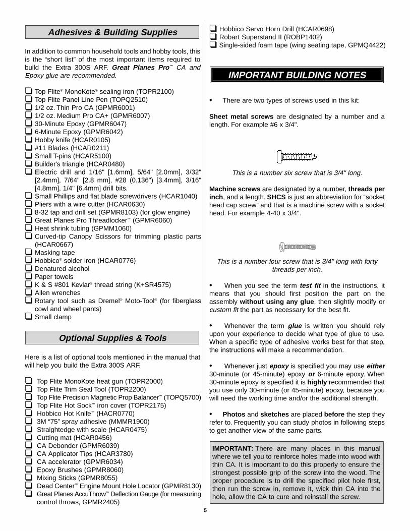
• There are two types of screws used in this kit:
Sheet metal screws are designated by a number and alength. For example #6 x 3/4".
This is a number six screw that is 3/4" long.
Machine screws are designated by a number, threads perinch, and a length. SHCS is just an abbreviation for “sockethead cap screw” and that is a machine screw with a sockethead. For example 4-40 x 3/4".
This is a number four screw that is 3/4" long with fortythreads per inch.
• When you see the term test fit in the instructions, itmeans that you should first position the part on theassembly without using any glue, then slightly modify orcustom fit the part as necessary for the best fit.
• Whenever the term glue is written you should relyupon your experience to decide what type of glue to use.When a specific type of adhesive works best for that step,the instructions will make a recommendation.
• Whenever just epoxy is specified you may use either30-minute (or 45-minute) epoxy or 6-minute epoxy. When30-minute epoxy is specified it is highly recommended thatyou use only 30-minute (or 45-minute) epoxy, because youwill need the working time and/or the additional strength.
• Photos and sketches are placed before the step theyrefer to. Frequently you can study photos in following stepsto get another view of the same parts.
IMPORTANT: There are many places in this manualwhere we tell you to reinforce holes made into wood withthin CA. It is important to do this properly to ensure thestrongest possible grip of the screw into the wood. Theproper procedure is to drill the specified pilot hole first,then run the screw in, remove it, wick thin CA into thehole, allow the CA to cure and reinstall the screw.
IMPORTANT BUILDING NOTES
Optional Supplies & Tools
Adhesives & Building Supplies
5
• The Extra 300S ARF is covered with Top FliteMonoKote film. Should repairs ever be required, MonoKotecan be patched with additional MonoKote purchasedseparately. MonoKote is packaged in six-foot rolls, but somehobby shops also sell it by the foot. If only a small piece ofMonoKote is needed for a minor patch, perhaps a fellowmodeler would give you some. MonoKote is applied with amodel airplane covering iron, but in an emergency a regulariron could be used. A roll of MonoKote includes fullinstructions for application.
Following are the colors used on this model and ordernumbers for six foot rolls.
Red–TOPQ0201Jet White–TOPQ0204
Sapphire Blue–TOPQ0226Metallic Gold–TOPQ0404
6
To order replacement parts for the Great Planes Extra 300S ARF, use the order numbers in the Replacement Parts Listthat follows. Replacement parts are available only as listed. Not all parts are available separately (an aileron cannot bepurchased separately, but is only available with the wing kit). Replacement parts are not available from Product Support,but can be purchased from hobby shops or mail order/Internet order firms. Hardware items (screws, nuts, bolts) are alsoavailable from these outlets. If you need assistance locating a dealer to purchase parts, visit www.greatplanes.com andclick on “Where to Buy.” If this kit is missing parts, contact Great Planes Product Support.
Replacement Parts List
Order Number Description How to PurchaseMissing pieces ......................Contact Product SupportInstruction manual.................Contact Product SupportFull-size plans .......................Not available
GPMA2329......................................Wing TubeGPMA2330......................................Wing SetGPMA2331......................................FuselageGPMA2332......................................Stab SetGPMA2333......................................RudderGPMA2334......................................Landing GearGPMA2335......................................Wheel Pants SetGPMA2336......................................CanopyGPMA2337......................................CowlGPMA2338......................................Decal SetGPMA2339......................................Stab Tubes (2)
ORDERING REPLACEMENT PARTS
................Contact Your HobbySupplier to PurchaseThese Items
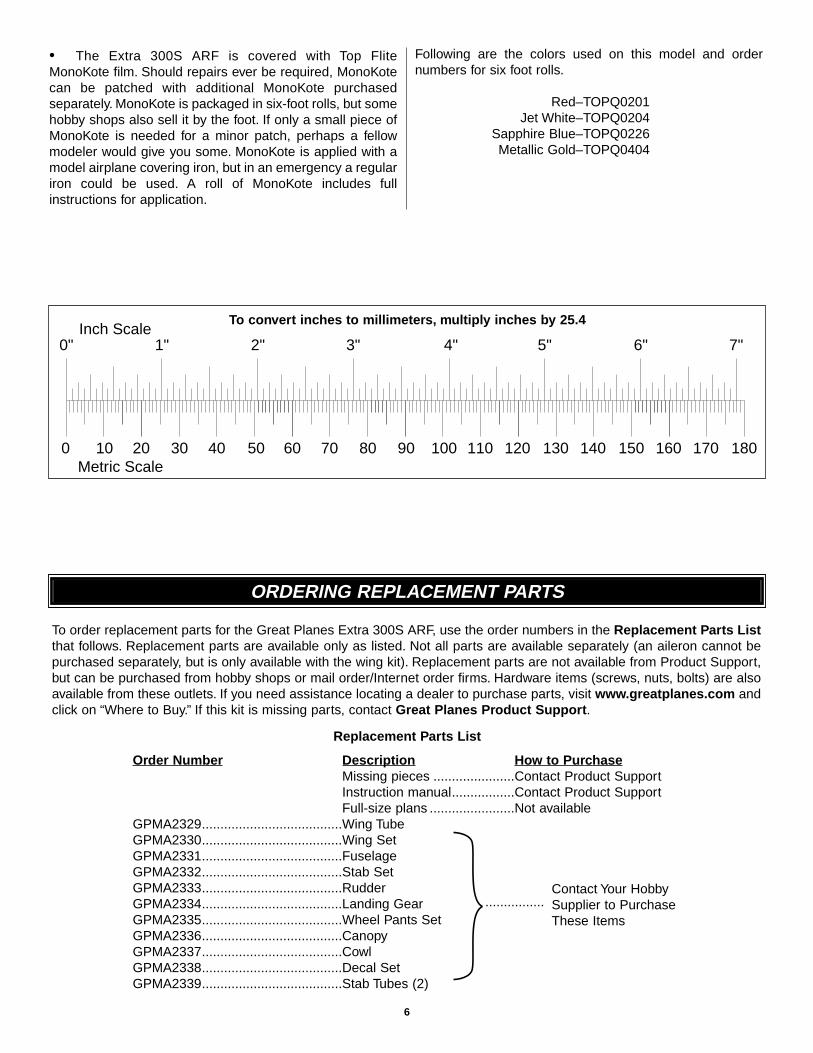
0" 1" 2" 3" 4" 5" 6" 7"
0 10 20 30 40 50 60 70 80 90 100 110 120 130 140 150 160 170 180
Inch Scale
Metric Scale
To convert inches to millimeters, multiply inches by 25.4
7
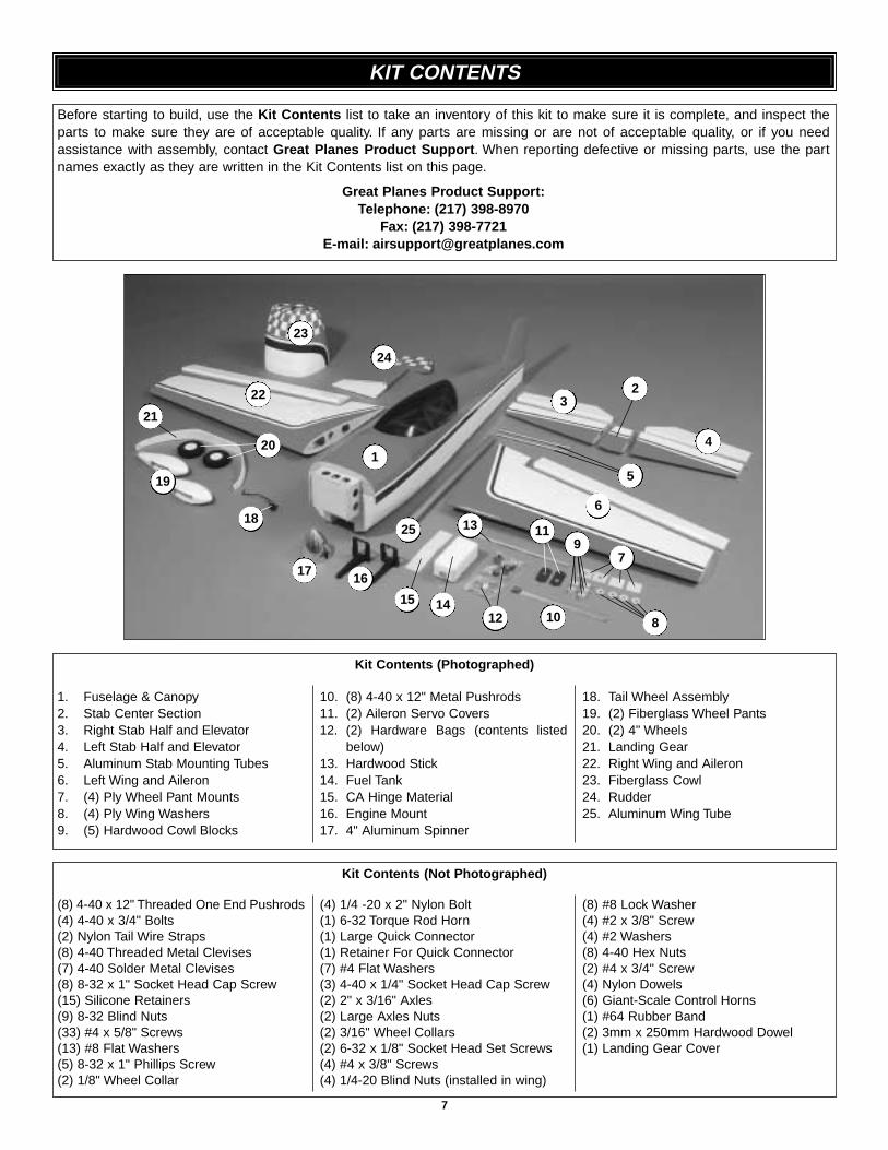
1. Fuselage & Canopy2. Stab Center Section3. Right Stab Half and Elevator4. Left Stab Half and Elevator5. Aluminum Stab Mounting Tubes6. Left Wing and Aileron7. (4) Ply Wheel Pant Mounts8. (4) Ply Wing Washers9. (5) Hardwood Cowl Blocks
10. (8) 4-40 x 12" Metal Pushrods11. (2) Aileron Servo Covers12. (2) Hardware Bags (contents listed
below)13. Hardwood Stick14. Fuel Tank15. CA Hinge Material16. Engine Mount17. 4" Aluminum Spinner
18. Tail Wheel Assembly19. (2) Fiberglass Wheel Pants20. (2) 4" Wheels21. Landing Gear22. Right Wing and Aileron23. Fiberglass Cowl24. Rudder25. Aluminum Wing Tube
(8) 4-40 x 12" Threaded One End Pushrods(4) 4-40 x 3/4" Bolts(2) Nylon Tail Wire Straps(8) 4-40 Threaded Metal Clevises(7) 4-40 Solder Metal Clevises(8) 8-32 x 1" Socket Head Cap Screw(15) Silicone Retainers(9) 8-32 Blind Nuts(33) #4 x 5/8" Screws(13) #8 Flat Washers(5) 8-32 x 1" Phillips Screw(2) 1/8" Wheel Collar
(4) 1/4 -20 x 2" Nylon Bolt(1) 6-32 Torque Rod Horn(1) Large Quick Connector(1) Retainer For Quick Connector(7) #4 Flat Washers(3) 4-40 x 1/4" Socket Head Cap Screw(2) 2" x 3/16" Axles(2) Large Axles Nuts(2) 3/16" Wheel Collars(2) 6-32 x 1/8" Socket Head Set Screws(4) #4 x 3/8" Screws(4) 1/4-20 Blind Nuts (installed in wing)
(8) #8 Lock Washer(4) #2 x 3/8" Screw(4) #2 Washers(8) 4-40 Hex Nuts(2) #4 x 3/4" Screw(4) Nylon Dowels(6) Giant-Scale Control Horns(1) #64 Rubber Band(2) 3mm x 250mm Hardwood Dowel(1) Landing Gear Cover
Kit Contents (Photographed)
Kit Contents (Not Photographed)
Before starting to build, use the Kit Contents list to take an inventory of this kit to make sure it is complete, and inspect theparts to make sure they are of acceptable quality. If any parts are missing or are not of acceptable quality, or if you needassistance with assembly, contact Great Planes Product Support. When reporting defective or missing parts, use the partnames exactly as they are written in the Kit Contents list on this page.
Great Planes Product Support:Telephone: (217) 398-8970
Fax: (217) 398-7721E-mail: [email protected]
KIT CONTENTS
22
24
23
1
23
4
5
6
79
8
11
10121415
1617
18
19
20
21
25 13
❏ 1. If you have not done so already, remove the majorparts of the kit from the box (wings, fuselage, cowl, tailparts, etc.) and inspect them for damage. If any parts aredamaged or missing, contact Product Support at theaddress or telephone number listed in the front cover.
❏ 2. Remove the masking tape and separate the aileronsfrom the wing and the elevators from the stab. Use acovering iron with a covering sock on high heat to tightenthe model’s covering if necessary. Apply pressure with a HotGlove over sheeted areas to thoroughly bond the coveringto the wood.
❏ 1. The first steps in the construction of this wing will bethe installation of the ailerons and the aileron servos. Theprocess described here will explain how to install the rightaileron and the right aileron servo. The process has to berepeated again to install the left aileron and the left aileronservo, or you can work on both at the same time.
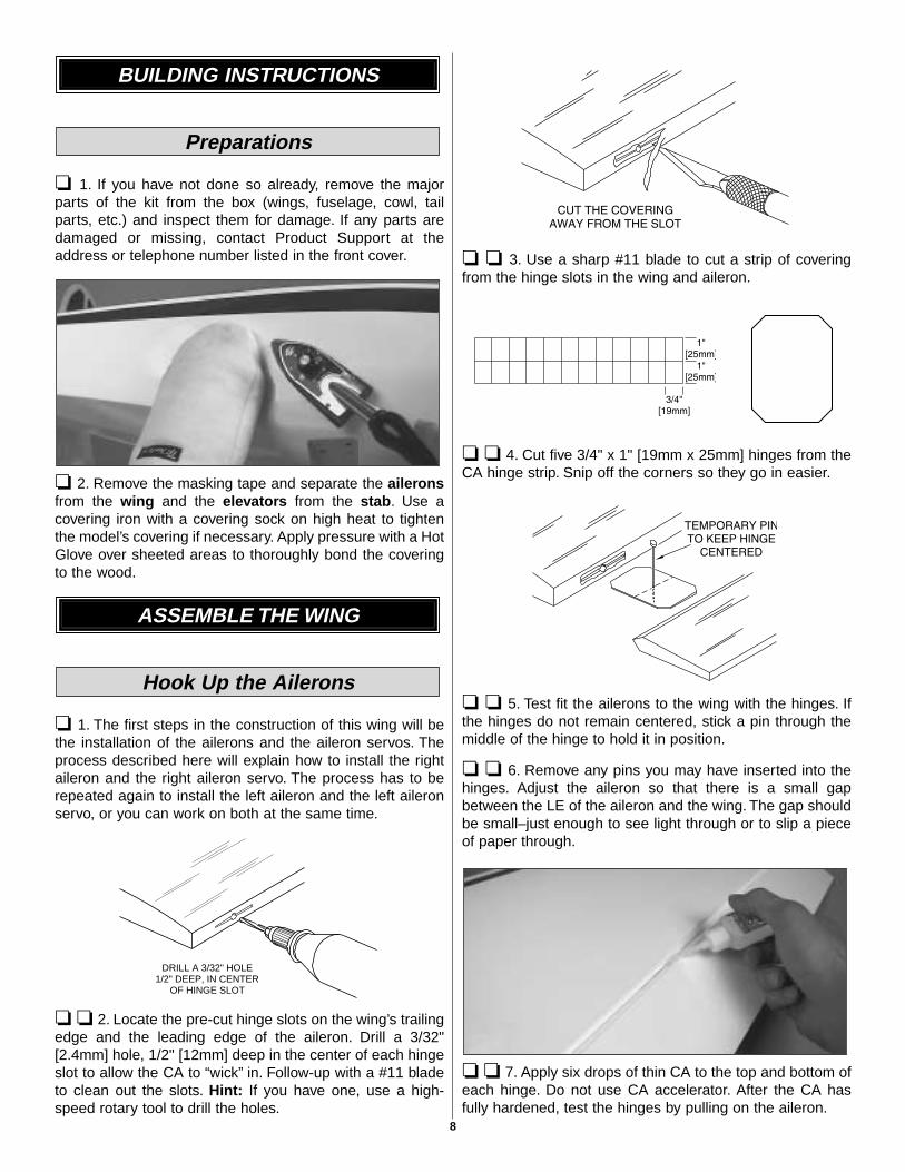
❏ ❏ 2. Locate the pre-cut hinge slots on the wing’s trailingedge and the leading edge of the aileron. Drill a 3/32"[2.4mm] hole, 1/2" [12mm] deep in the center of each hingeslot to allow the CA to “wick” in. Follow-up with a #11 bladeto clean out the slots. Hint: If you have one, use a high-speed rotary tool to drill the holes.
❏ ❏ 3. Use a sharp #11 blade to cut a strip of coveringfrom the hinge slots in the wing and aileron.
❏ ❏ 4. Cut five 3/4" x 1" [19mm x 25mm] hinges from theCA hinge strip. Snip off the corners so they go in easier.
❏ ❏ 5. Test fit the ailerons to the wing with the hinges. Ifthe hinges do not remain centered, stick a pin through themiddle of the hinge to hold it in position.
❏ ❏ 6. Remove any pins you may have inserted into thehinges. Adjust the aileron so that there is a small gapbetween the LE of the aileron and the wing. The gap shouldbe small–just enough to see light through or to slip a pieceof paper through.
❏ ❏ 7. Apply six drops of thin CA to the top and bottom ofeach hinge. Do not use CA accelerator. After the CA hasfully hardened, test the hinges by pulling on the aileron.
DRILL A 3/32" HOLE1/2" DEEP, IN CENTER
OF HINGE SLOT
Hook Up the Ailerons
ASSEMBLE THE WING
Preparations
BUILDING INSTRUCTIONS
8
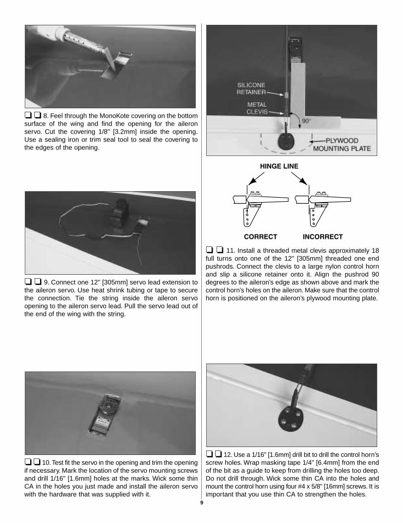
❏ ❏ 8. Feel through the MonoKote covering on the bottomsurface of the wing and find the opening for the aileronservo. Cut the covering 1/8" [3.2mm] inside the opening.Use a sealing iron or trim seal tool to seal the covering tothe edges of the opening.
❏ ❏ 9. Connect one 12" [305mm] servo lead extension tothe aileron servo. Use heat shrink tubing or tape to securethe connection. Tie the string inside the aileron servoopening to the aileron servo lead. Pull the servo lead out ofthe end of the wing with the string.
❏ ❏ 10.Test fit the servo in the opening and trim the openingif necessary. Mark the location of the servo mounting screwsand drill 1/16" [1.6mm] holes at the marks. Wick some thinCA in the holes you just made and install the aileron servowith the hardware that was supplied with it.
❏ ❏ 11. Install a threaded metal clevis approximately 18full turns onto one of the 12" [305mm] threaded one endpushrods. Connect the clevis to a large nylon control hornand slip a silicone retainer onto it. Align the pushrod 90degrees to the aileron’s edge as shown above and mark thecontrol horn’s holes on the aileron. Make sure that the controlhorn is positioned on the aileron’s plywood mounting plate.
❏ ❏ 12. Use a 1/16" [1.6mm] drill bit to drill the control horn’sscrew holes. Wrap masking tape 1/4" [6.4mm] from the endof the bit as a guide to keep from drilling the holes too deep.Do not drill through. Wick some thin CA into the holes andmount the control horn using four #4 x 5/8" [16mm] screws. It isimportant that you use thin CA to strengthen the holes.
9
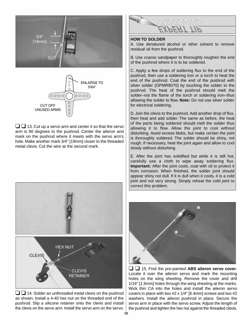
❏ ❏ 13. Cut up a servo arm and center it so that the servoarm is 90 degrees to the pushrod. Center the aileron andmark on the pushrod where it meets with the servo arm’shole. Make another mark 3/4" [19mm] closer to the threadedmetal clevis. Cut the wire at the second mark.
❏ ❏ 14. Solder an unthreaded metal clevis on the pushrodas shown. Install a 4-40 hex nut on the threaded end of thepushrod. Slip a silicone retainer onto the clevis and installthe clevis on the servo arm. Install the servo arm on the servo.
❏ ❏ 15. Find the pre-painted ABS aileron servo cover.Locate it over the aileron servo and mark the mountingholes on the wing sheeting. Remove the cover and drill1/16" [1.6mm] holes through the wing sheeting at the marks.Wick thin CA into the holes and install the aileron servocovers in place with two #2 x 1/4" [6.4mm] screws and two #2washers. Install the aileron pushrod in place. Secure theservo arm in place with the servo screw. Adjust the length ofthe pushrod and tighten the hex nut against the threaded clevis.
HOW TO SOLDERA. Use denatured alcohol or other solvent to removeresidual oil from the pushrod.
B. Use coarse sandpaper to thoroughly roughen the endof the pushrod where it is to be soldered.
C. Apply a few drops of soldering flux to the end of thepushrod, then use a soldering iron or a torch to heat theend of the pushrod. Coat the end of the pushrod withsilver solder (GPMR8070) by touching the solder to thepushrod. The heat of the pushrod should melt thesolder–not the flame of the torch or soldering iron–thusallowing the solder to flow. Note: Do not use silver solderfor electrical soldering.
D. Join the clevis to the pushrod. Add another drop of flux,then heat and add solder. The same as before, the heatof the parts being soldered should melt the solder thusallowing it to flow. Allow the joint to cool withoutdisturbing. Avoid excess blobs, but make certain the jointis thoroughly soldered. The solder should be shiny, notrough. If necessary, heat the joint again and allow to coolslowly without disturbing.
E. After the joint has solidified but while it is still hot,carefully use a cloth to wipe away soldering flux.Important: After the joint cools, coat with oil to protect itfrom corrosion. When finished, the solder joint shouldappear shiny not dull. If it is dull when it cools, it is a coldjoint and not very strong. Simply reheat the cold joint tocorrect this problem.
10
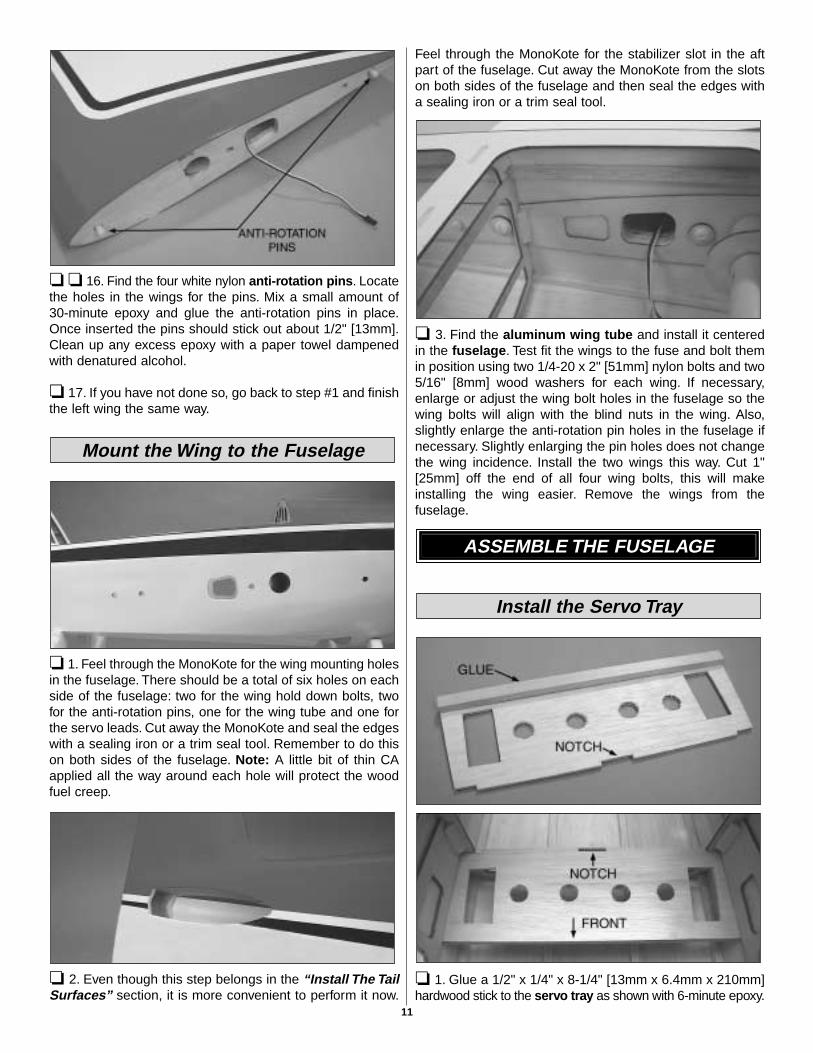
❏ ❏ 16. Find the four white nylon anti-rotation pins. Locatethe holes in the wings for the pins. Mix a small amount of30-minute epoxy and glue the anti-rotation pins in place.Once inserted the pins should stick out about 1/2" [13mm].Clean up any excess epoxy with a paper towel dampenedwith denatured alcohol.
❏ 17. If you have not done so, go back to step #1 and finishthe left wing the same way.
❏ 1. Feel through the MonoKote for the wing mounting holesin the fuselage. There should be a total of six holes on eachside of the fuselage: two for the wing hold down bolts, twofor the anti-rotation pins, one for the wing tube and one forthe servo leads. Cut away the MonoKote and seal the edgeswith a sealing iron or a trim seal tool. Remember to do thison both sides of the fuselage. Note: A little bit of thin CAapplied all the way around each hole will protect the woodfuel creep.
❏ 2. Even though this step belongs in the “Install The TailSurfaces” section, it is more convenient to perform it now.
Feel through the MonoKote for the stabilizer slot in the aftpart of the fuselage. Cut away the MonoKote from the slotson both sides of the fuselage and then seal the edges witha sealing iron or a trim seal tool.
❏ 3. Find the aluminum wing tube and install it centeredin the fuselage. Test fit the wings to the fuse and bolt themin position using two 1/4-20 x 2" [51mm] nylon bolts and two5/16" [8mm] wood washers for each wing. If necessary,enlarge or adjust the wing bolt holes in the fuselage so thewing bolts will align with the blind nuts in the wing. Also,slightly enlarge the anti-rotation pin holes in the fuselage ifnecessary. Slightly enlarging the pin holes does not changethe wing incidence. Install the two wings this way. Cut 1"[25mm] off the end of all four wing bolts, this will makeinstalling the wing easier. Remove the wings from thefuselage.
❏ 1. Glue a 1/2" x 1/4" x 8-1/4" [13mm x 6.4mm x 210mm]hardwood stick to the servo tray as shown with 6-minute epoxy.
Install the Servo Tray
ASSEMBLE THE FUSELAGE
Mount the Wing to the Fuselage
11
Once the glue has cured, install the servo tray in place asshown using 6-minute epoxy. The notched side fits againstthe former.
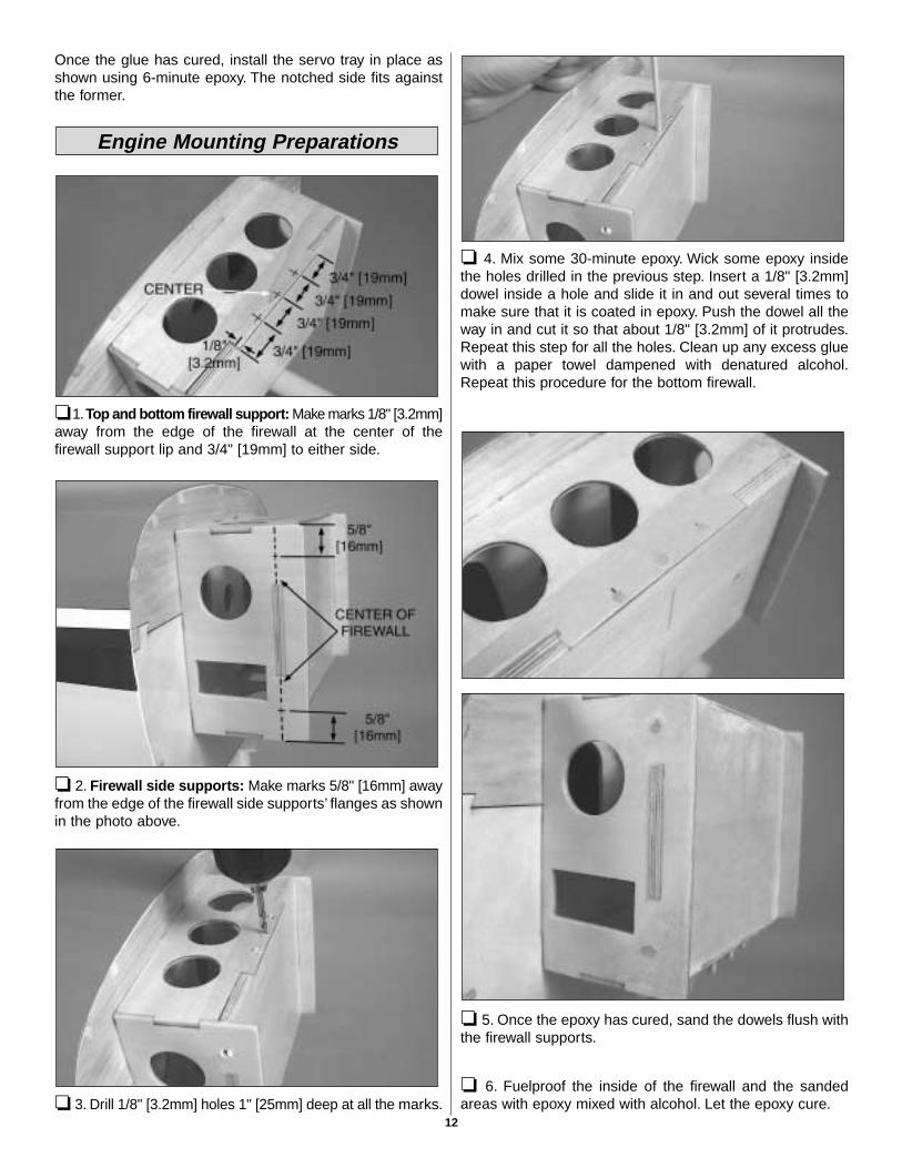
❏ 1.Top and bottom firewall support: Make marks 1/8" [3.2mm]away from the edge of the firewall at the center of thefirewall support lip and 3/4" [19mm] to either side.
❏ 2. Firewall side supports: Make marks 5/8" [16mm] awayfrom the edge of the firewall side supports’ flanges as shownin the photo above.
❏ 3. Drill 1/8" [3.2mm] holes 1" [25mm] deep at all the marks.
❏ 4. Mix some 30-minute epoxy. Wick some epoxy insidethe holes drilled in the previous step. Insert a 1/8" [3.2mm]dowel inside a hole and slide it in and out several times tomake sure that it is coated in epoxy. Push the dowel all theway in and cut it so that about 1/8" [3.2mm] of it protrudes.Repeat this step for all the holes. Clean up any excess gluewith a paper towel dampened with denatured alcohol.Repeat this procedure for the bottom firewall.
❏ 5. Once the epoxy has cured, sand the dowels flush withthe firewall supports.
❏ 6. Fuelproof the inside of the firewall and the sandedareas with epoxy mixed with alcohol. Let the epoxy cure.
Engine Mounting Preparations
12
Both gas and glow engines can be installed on this airplaneso two installations will be shown in this instruction book.The first installation shown will be of an O.S.® 1.60 FX(OSMG0661) glow engine. The second installation shownwill be of a Fuji BT-50SA (FJIG0050) gas engine. Bothengine installations are typical of engines of their respectivesize and type. Follow this instruction manual step by step ifyou are installing either of these engines. Use thisinstruction manual as a guide if you are installing othersimilar engines.
If you are installing a gas engine, skip the “Install a GlowEngine” section and go to page 15, “Install a Gas Engine.”
❏ 1. Cut the engine mount template from page 39. Usespray adhesive or tape to temporarily attach the template tothe firewall. Align the template using the vertical andhorizontal lines stamped into the firewall. Drill 3/16" [4.8mm]holes through the firewall at the marks.
❏ 2. Remove the engine mount template. Install four 8-32blind nuts on the back of the firewall using one 8-32 x 1"[25mm] SHCS and a #8 flat washer as shown. Use a smallamount of epoxy on the blind nuts to keep them in place. Donot get epoxy in the threads.
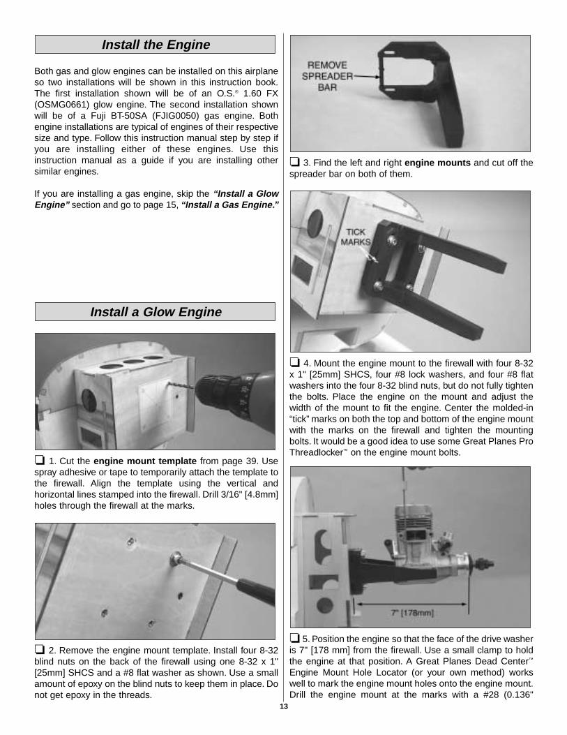
❏ 3. Find the left and right engine mounts and cut off thespreader bar on both of them.
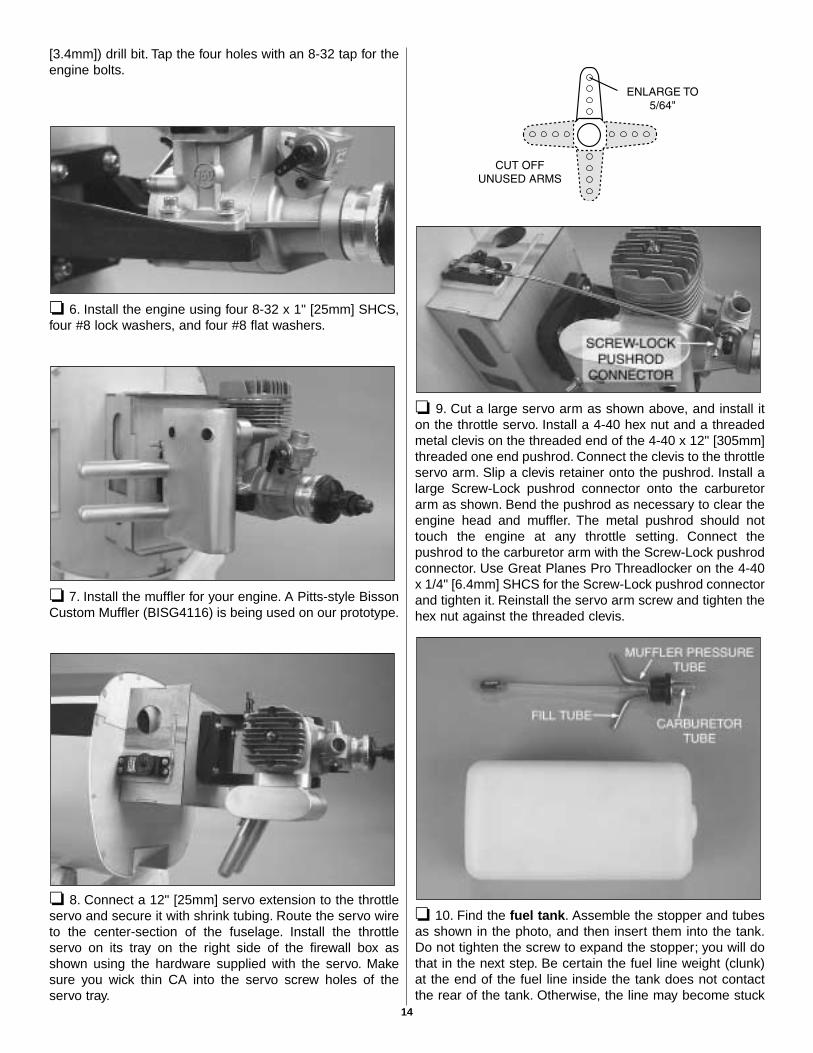
❏ 4. Mount the engine mount to the firewall with four 8-32x 1" [25mm] SHCS, four #8 lock washers, and four #8 flatwashers into the four 8-32 blind nuts, but do not fully tightenthe bolts. Place the engine on the mount and adjust thewidth of the mount to fit the engine. Center the molded-in“tick” marks on both the top and bottom of the engine mountwith the marks on the firewall and tighten the mountingbolts. It would be a good idea to use some Great Planes ProThreadlocker™ on the engine mount bolts.
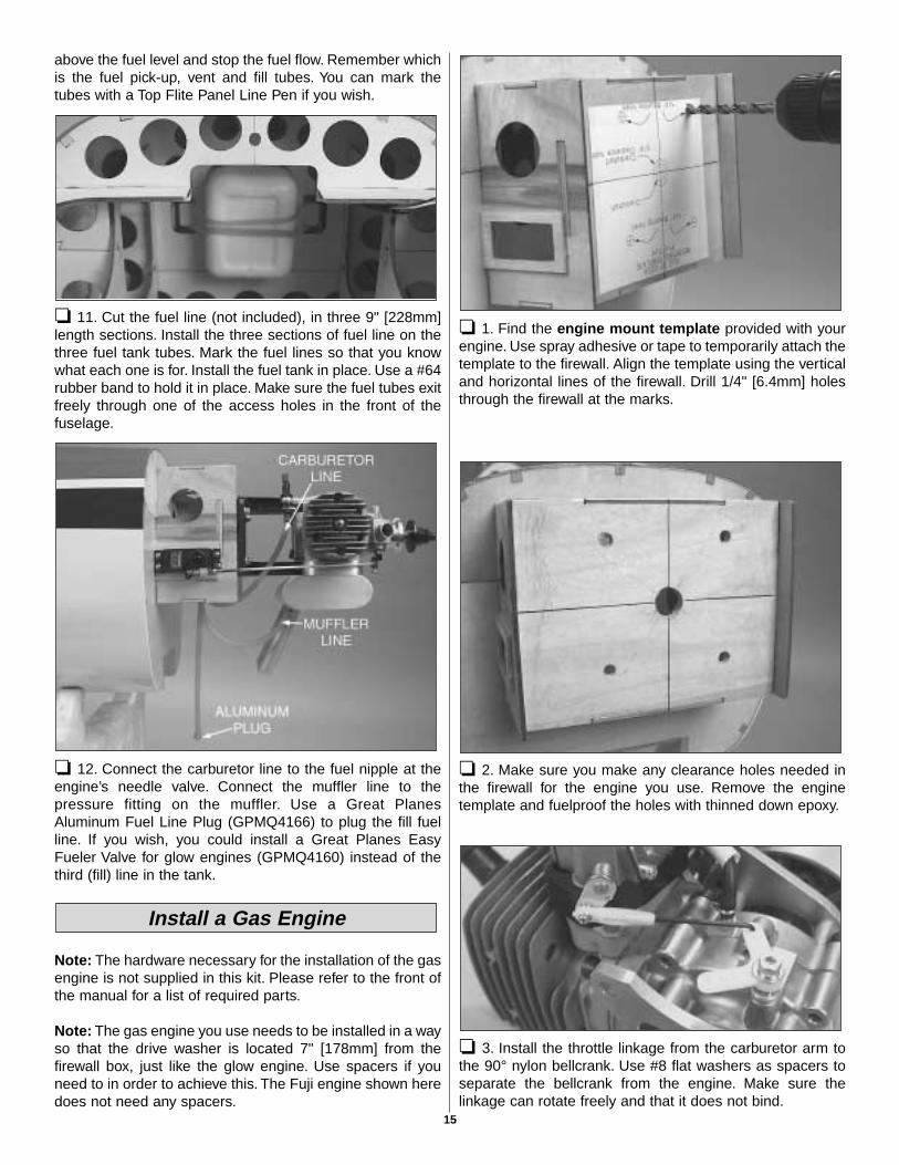
❏ 5. Position the engine so that the face of the drive washeris 7" [178 mm] from the firewall. Use a small clamp to holdthe engine at that position. A Great Planes Dead Center™
Engine Mount Hole Locator (or your own method) workswell to mark the engine mount holes onto the engine mount.Drill the engine mount at the marks with a #28 (0.136"
Install a Glow Engine
Install the Engine
13
[3.4mm]) drill bit. Tap the four holes with an 8-32 tap for theengine bolts.
❏ 6. Install the engine using four 8-32 x 1" [25mm] SHCS,four #8 lock washers, and four #8 flat washers.
❏ 7. Install the muffler for your engine. A Pitts-style BissonCustom Muffler (BISG4116) is being used on our prototype.
❏ 8. Connect a 12" [25mm] servo extension to the throttleservo and secure it with shrink tubing. Route the servo wireto the center-section of the fuselage. Install the throttleservo on its tray on the right side of the firewall box asshown using the hardware supplied with the servo. Makesure you wick thin CA into the servo screw holes of theservo tray.
❏ 9. Cut a large servo arm as shown above, and install iton the throttle servo. Install a 4-40 hex nut and a threadedmetal clevis on the threaded end of the 4-40 x 12" [305mm]threaded one end pushrod. Connect the clevis to the throttleservo arm. Slip a clevis retainer onto the pushrod. Install alarge Screw-Lock pushrod connector onto the carburetorarm as shown. Bend the pushrod as necessary to clear theengine head and muffler. The metal pushrod should nottouch the engine at any throttle setting. Connect thepushrod to the carburetor arm with the Screw-Lock pushrodconnector. Use Great Planes Pro Threadlocker on the 4-40x 1/4" [6.4mm] SHCS for the Screw-Lock pushrod connectorand tighten it. Reinstall the servo arm screw and tighten thehex nut against the threaded clevis.
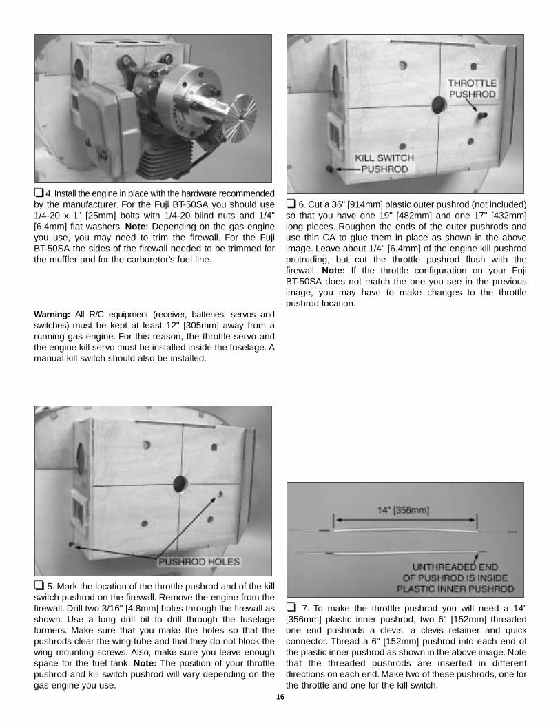
❏ 10. Find the fuel tank. Assemble the stopper and tubesas shown in the photo, and then insert them into the tank.Do not tighten the screw to expand the stopper; you will dothat in the next step. Be certain the fuel line weight (clunk)at the end of the fuel line inside the tank does not contactthe rear of the tank. Otherwise, the line may become stuck
14
above the fuel level and stop the fuel flow. Remember whichis the fuel pick-up, vent and fill tubes. You can mark thetubes with a Top Flite Panel Line Pen if you wish.
❏ 11. Cut the fuel line (not included), in three 9" [228mm]length sections. Install the three sections of fuel line on thethree fuel tank tubes. Mark the fuel lines so that you knowwhat each one is for. Install the fuel tank in place. Use a #64rubber band to hold it in place. Make sure the fuel tubes exitfreely through one of the access holes in the front of thefuselage.
❏ 12. Connect the carburetor line to the fuel nipple at theengine’s needle valve. Connect the muffler line to thepressure fitting on the muffler. Use a Great PlanesAluminum Fuel Line Plug (GPMQ4166) to plug the fill fuelline. If you wish, you could install a Great Planes EasyFueler Valve for glow engines (GPMQ4160) instead of thethird (fill) line in the tank.
Note: The hardware necessary for the installation of the gasengine is not supplied in this kit. Please refer to the front ofthe manual for a list of required parts.
Note: The gas engine you use needs to be installed in a wayso that the drive washer is located 7" [178mm] from thefirewall box, just like the glow engine. Use spacers if youneed to in order to achieve this. The Fuji engine shown heredoes not need any spacers.
❏ 1. Find the engine mount template provided with yourengine. Use spray adhesive or tape to temporarily attach thetemplate to the firewall. Align the template using the verticaland horizontal lines of the firewall. Drill 1/4" [6.4mm] holesthrough the firewall at the marks.
❏ 2. Make sure you make any clearance holes needed inthe firewall for the engine you use. Remove the enginetemplate and fuelproof the holes with thinned down epoxy.
❏ 3. Install the throttle linkage from the carburetor arm tothe 90° nylon bellcrank. Use #8 flat washers as spacers toseparate the bellcrank from the engine. Make sure thelinkage can rotate freely and that it does not bind.
Install a Gas Engine
15
❏ 4. Install the engine in place with the hardware recommendedby the manufacturer. For the Fuji BT-50SA you should use1/4-20 x 1" [25mm] bolts with 1/4-20 blind nuts and 1/4"[6.4mm] flat washers. Note: Depending on the gas engineyou use, you may need to trim the firewall. For the FujiBT-50SA the sides of the firewall needed to be trimmed forthe muffler and for the carburetor’s fuel line.
Warning: All R/C equipment (receiver, batteries, servos andswitches) must be kept at least 12" [305mm] away from arunning gas engine. For this reason, the throttle servo andthe engine kill servo must be installed inside the fuselage. Amanual kill switch should also be installed.
❏ 5. Mark the location of the throttle pushrod and of the killswitch pushrod on the firewall. Remove the engine from thefirewall. Drill two 3/16" [4.8mm] holes through the firewall asshown. Use a long drill bit to drill through the fuselageformers. Make sure that you make the holes so that thepushrods clear the wing tube and that they do not block thewing mounting screws. Also, make sure you leave enoughspace for the fuel tank. Note: The position of your throttlepushrod and kill switch pushrod will vary depending on thegas engine you use.
❏ 6. Cut a 36" [914mm] plastic outer pushrod (not included)so that you have one 19" [482mm] and one 17" [432mm]long pieces. Roughen the ends of the outer pushrods anduse thin CA to glue them in place as shown in the aboveimage. Leave about 1/4" [6.4mm] of the engine kill pushrodprotruding, but cut the throttle pushrod flush with thefirewall. Note: If the throttle configuration on your FujiBT-50SA does not match the one you see in the previousimage, you may have to make changes to the throttlepushrod location.
❏ 7. To make the throttle pushrod you will need a 14"[356mm] plastic inner pushrod, two 6" [152mm] threadedone end pushrods a clevis, a clevis retainer and quickconnector. Thread a 6" [152mm] pushrod into each end ofthe plastic inner pushrod as shown in the above image. Notethat the threaded pushrods are inserted in differentdirections on each end. Make two of these pushrods, one forthe throttle and one for the kill switch.
16
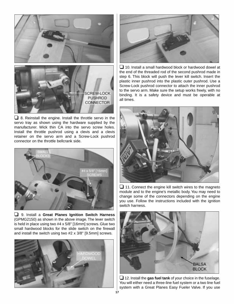
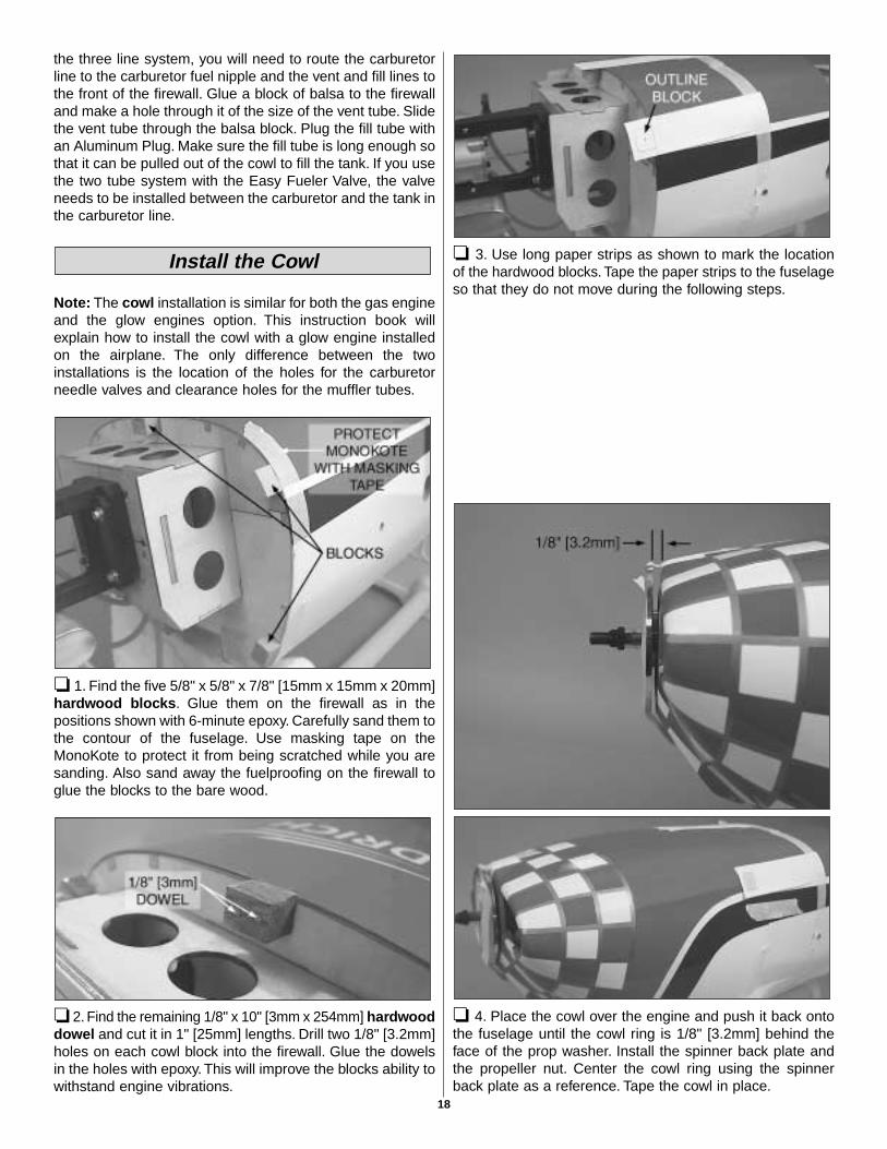
❏ 8. Reinstall the engine. Install the throttle servo in theservo tray as shown using the hardware supplied by themanufacturer. Wick thin CA into the servo screw holes.Install the throttle pushrod using a clevis and a clevisretainer on the servo arm and a Screw-Lock pushrodconnector on the throttle bellcrank side.
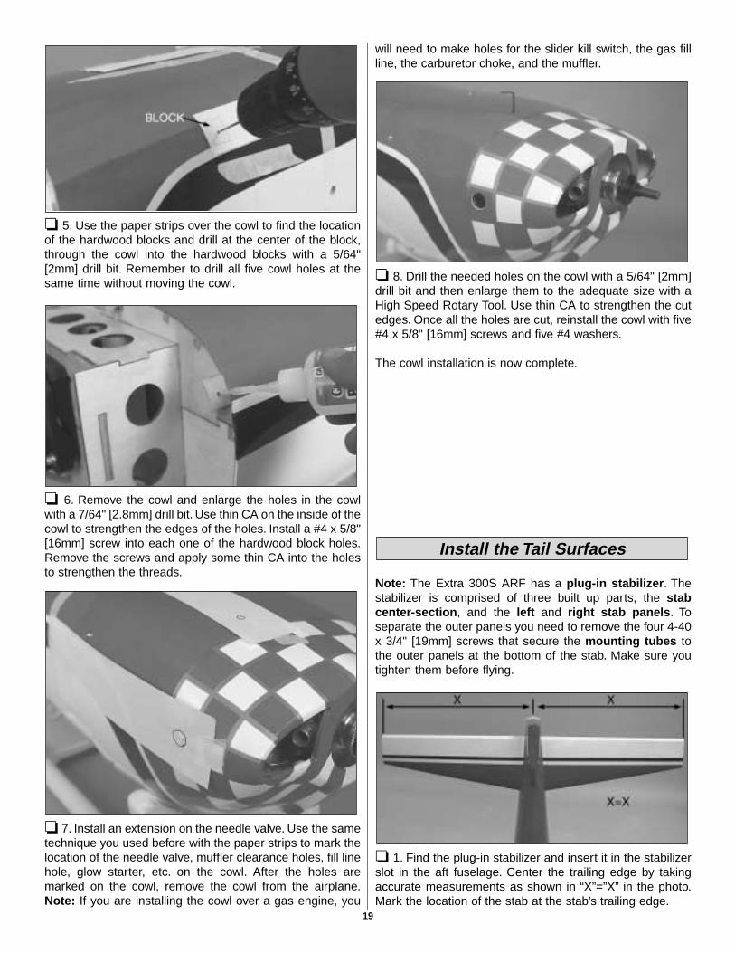
❏ 9. Install a Great Planes Ignition Switch Harness(GPMG2150) as shown in the above image. The lever switchis held in place using two #4 x 5/8" [16mm] screws. Glue twosmall hardwood blocks for the slide switch on the firewalland install the switch using two #2 x 3/8" [9.5mm] screws.
❏ 10. Install a small hardwood block or hardwood dowel atthe end of the threaded rod of the second pushrod made instep 6. This block will push the lever kill switch. Insert theplastic inner pushrod into the plastic outer pushrod. Use aScrew-Lock pushrod connector to attach the inner pushrodto the servo arm. Make sure the setup works freely, with nobinding. It is a safety device and must be operable atall times.
❏ 11. Connect the engine kill switch wires to the magnetomodule and to the engine’s metallic body. You may need tochange some of the connectors depending on the engineyou use. Follow the instructions included with the ignitionswitch harness.
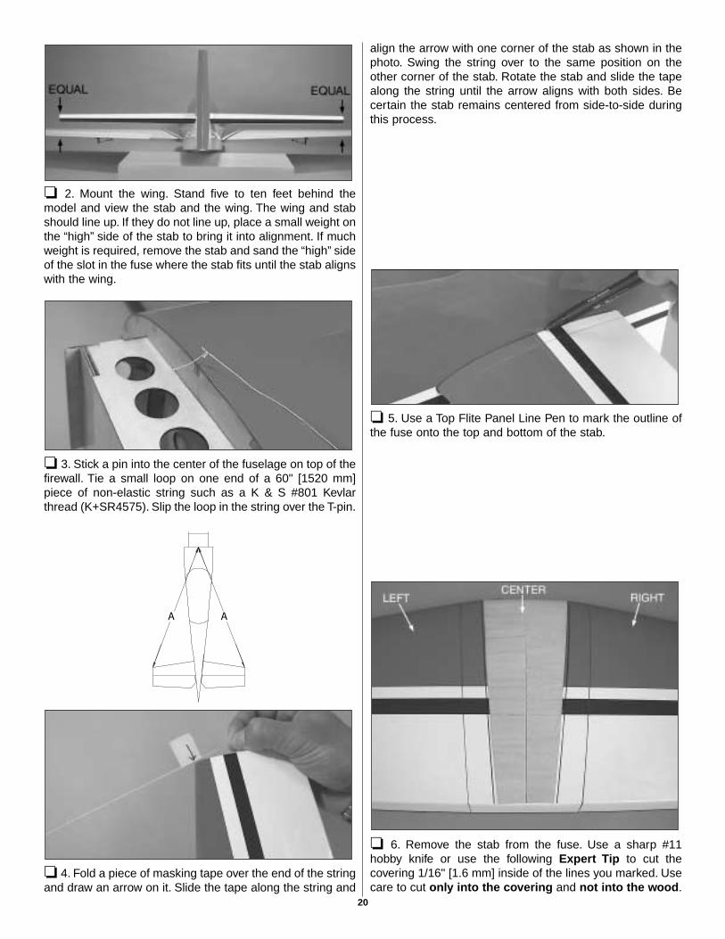
❏ 12. Install the gas fuel tank of your choice in the fuselage.You will either need a three-line fuel system or a two line fuelsystem with a Great Planes Easy Fueler Valve. If you use
17
the three line system, you will need to route the carburetorline to the carburetor fuel nipple and the vent and fill lines tothe front of the firewall. Glue a block of balsa to the firewalland make a hole through it of the size of the vent tube. Slidethe vent tube through the balsa block. Plug the fill tube withan Aluminum Plug. Make sure the fill tube is long enough sothat it can be pulled out of the cowl to fill the tank. If you usethe two tube system with the Easy Fueler Valve, the valveneeds to be installed between the carburetor and the tank inthe carburetor line.
Note: The cowl installation is similar for both the gas engineand the glow engines option. This instruction book willexplain how to install the cowl with a glow engine installedon the airplane. The only difference between the twoinstallations is the location of the holes for the carburetorneedle valves and clearance holes for the muffler tubes.
❏ 1. Find the five 5/8" x 5/8" x 7/8" [15mm x 15mm x 20mm]hardwood blocks. Glue them on the firewall as in thepositions shown with 6-minute epoxy. Carefully sand them tothe contour of the fuselage. Use masking tape on theMonoKote to protect it from being scratched while you aresanding. Also sand away the fuelproofing on the firewall toglue the blocks to the bare wood.
❏ 2. Find the remaining 1/8" x 10" [3mm x 254mm] hardwooddowel and cut it in 1" [25mm] lengths. Drill two 1/8" [3.2mm]holes on each cowl block into the firewall. Glue the dowelsin the holes with epoxy. This will improve the blocks ability towithstand engine vibrations.
❏ 3. Use long paper strips as shown to mark the locationof the hardwood blocks. Tape the paper strips to the fuselageso that they do not move during the following steps.
❏ 4. Place the cowl over the engine and push it back ontothe fuselage until the cowl ring is 1/8" [3.2mm] behind theface of the prop washer. Install the spinner back plate andthe propeller nut. Center the cowl ring using the spinnerback plate as a reference. Tape the cowl in place.
Install the Cowl
18
❏ 5. Use the paper strips over the cowl to find the locationof the hardwood blocks and drill at the center of the block,through the cowl into the hardwood blocks with a 5/64"[2mm] drill bit. Remember to drill all five cowl holes at thesame time without moving the cowl.
❏ 6. Remove the cowl and enlarge the holes in the cowlwith a 7/64" [2.8mm] drill bit. Use thin CA on the inside of thecowl to strengthen the edges of the holes. Install a #4 x 5/8"[16mm] screw into each one of the hardwood block holes.Remove the screws and apply some thin CA into the holesto strengthen the threads.
❏ 7. Install an extension on the needle valve. Use the sametechnique you used before with the paper strips to mark thelocation of the needle valve, muffler clearance holes, fill linehole, glow starter, etc. on the cowl. After the holes aremarked on the cowl, remove the cowl from the airplane.Note: If you are installing the cowl over a gas engine, you
will need to make holes for the slider kill switch, the gas fillline, the carburetor choke, and the muffler.
❏ 8. Drill the needed holes on the cowl with a 5/64" [2mm]drill bit and then enlarge them to the adequate size with aHigh Speed Rotary Tool. Use thin CA to strengthen the cutedges. Once all the holes are cut, reinstall the cowl with five#4 x 5/8" [16mm] screws and five #4 washers.
The cowl installation is now complete.
Note: The Extra 300S ARF has a plug-in stabilizer. Thestabilizer is comprised of three built up parts, the stabcenter-section, and the left and right stab panels. Toseparate the outer panels you need to remove the four 4-40x 3/4" [19mm] screws that secure the mounting tubes tothe outer panels at the bottom of the stab. Make sure youtighten them before flying.
❏ 1. Find the plug-in stabilizer and insert it in the stabilizerslot in the aft fuselage. Center the trailing edge by takingaccurate measurements as shown in “X”=”X” in the photo.Mark the location of the stab at the stab’s trailing edge.
Install the Tail Surfaces
19
❏ 2. Mount the wing. Stand five to ten feet behind themodel and view the stab and the wing. The wing and stabshould line up. If they do not line up, place a small weight onthe “high” side of the stab to bring it into alignment. If muchweight is required, remove the stab and sand the “high” sideof the slot in the fuse where the stab fits until the stab alignswith the wing.
❏ 3. Stick a pin into the center of the fuselage on top of thefirewall. Tie a small loop on one end of a 60" [1520 mm]piece of non-elastic string such as a K & S #801 Kevlarthread (K+SR4575). Slip the loop in the string over the T-pin.
❏ 4. Fold a piece of masking tape over the end of the stringand draw an arrow on it. Slide the tape along the string and
align the arrow with one corner of the stab as shown in thephoto. Swing the string over to the same position on theother corner of the stab. Rotate the stab and slide the tapealong the string until the arrow aligns with both sides. Becertain the stab remains centered from side-to-side duringthis process.
❏ 5. Use a Top Flite Panel Line Pen to mark the outline ofthe fuse onto the top and bottom of the stab.
❏ 6. Remove the stab from the fuse. Use a sharp #11hobby knife or use the following Expert Tip to cut thecovering 1/16" [1.6 mm] inside of the lines you marked. Usecare to cut only into the covering and not into the wood.
20
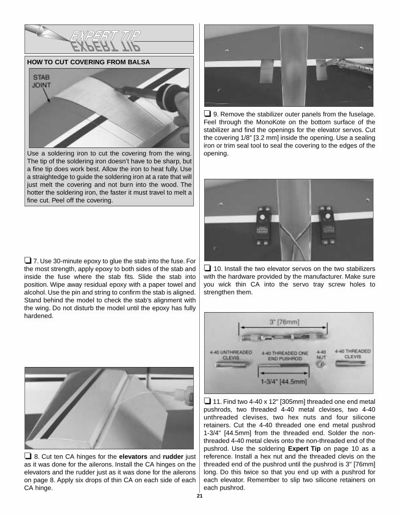
❏ 7. Use 30-minute epoxy to glue the stab into the fuse. Forthe most strength, apply epoxy to both sides of the stab andinside the fuse where the stab fits. Slide the stab intoposition. Wipe away residual epoxy with a paper towel andalcohol. Use the pin and string to confirm the stab is aligned.Stand behind the model to check the stab’s alignment withthe wing. Do not disturb the model until the epoxy has fullyhardened.
❏ 8. Cut ten CA hinges for the elevators and rudder justas it was done for the ailerons. Install the CA hinges on theelevators and the rudder just as it was done for the aileronson page 8. Apply six drops of thin CA on each side of eachCA hinge.
❏ 9. Remove the stabilizer outer panels from the fuselage.Feel through the MonoKote on the bottom surface of thestabilizer and find the openings for the elevator servos. Cutthe covering 1/8" [3.2 mm] inside the opening. Use a sealingiron or trim seal tool to seal the covering to the edges of theopening.
❏ 10. Install the two elevator servos on the two stabilizerswith the hardware provided by the manufacturer. Make sureyou wick thin CA into the servo tray screw holes tostrengthen them.
❏ 11. Find two 4-40 x 12" [305mm] threaded one end metalpushrods, two threaded 4-40 metal clevises, two 4-40unthreaded clevises, two hex nuts and four siliconeretainers. Cut the 4-40 threaded one end metal pushrod 1-3/4" [44.5mm] from the threaded end. Solder the non-threaded 4-40 metal clevis onto the non-threaded end of thepushrod. Use the soldering Expert Tip on page 10 as areference. Install a hex nut and the threaded clevis on thethreaded end of the pushrod until the pushrod is 3" [76mm]long. Do this twice so that you end up with a pushrod foreach elevator. Remember to slip two silicone retainers oneach pushrod.
HOW TO CUT COVERING FROM BALSA
Use a soldering iron to cut the covering from the wing.The tip of the soldering iron doesn’t have to be sharp, buta fine tip does work best. Allow the iron to heat fully. Usea straightedge to guide the soldering iron at a rate that willjust melt the covering and not burn into the wood. Thehotter the soldering iron, the faster it must travel to melt afine cut. Peel off the covering.
21
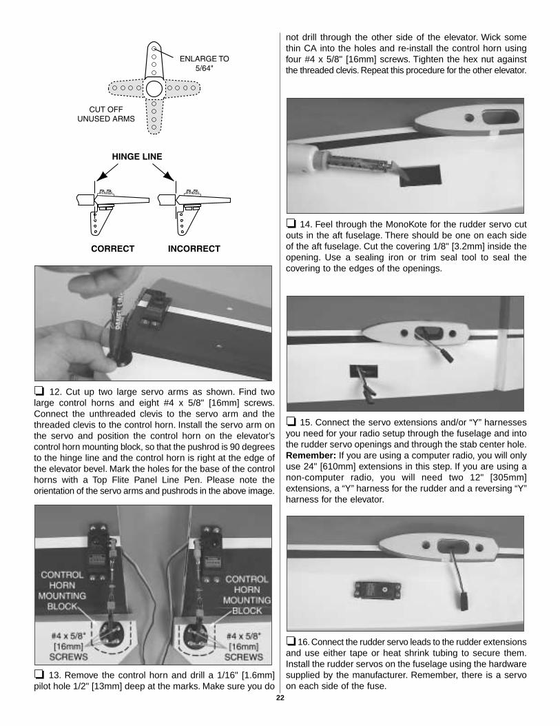
❏ 12. Cut up two large servo arms as shown. Find twolarge control horns and eight #4 x 5/8" [16mm] screws.Connect the unthreaded clevis to the servo arm and thethreaded clevis to the control horn. Install the servo arm onthe servo and position the control horn on the elevator’scontrol horn mounting block, so that the pushrod is 90 degreesto the hinge line and the control horn is right at the edge ofthe elevator bevel. Mark the holes for the base of the controlhorns with a Top Flite Panel Line Pen. Please note theorientation of the servo arms and pushrods in the above image.
❏ 13. Remove the control horn and drill a 1/16" [1.6mm]pilot hole 1/2" [13mm] deep at the marks. Make sure you do
not drill through the other side of the elevator. Wick somethin CA into the holes and re-install the control horn usingfour #4 x 5/8" [16mm] screws. Tighten the hex nut againstthe threaded clevis. Repeat this procedure for the other elevator.
❏ 14. Feel through the MonoKote for the rudder servo cutouts in the aft fuselage. There should be one on each sideof the aft fuselage. Cut the covering 1/8" [3.2mm] inside theopening. Use a sealing iron or trim seal tool to seal thecovering to the edges of the openings.
❏ 15. Connect the servo extensions and/or “Y” harnessesyou need for your radio setup through the fuselage and intothe rudder servo openings and through the stab center hole.Remember: If you are using a computer radio, you will onlyuse 24" [610mm] extensions in this step. If you are using anon-computer radio, you will need two 12" [305mm]extensions, a “Y” harness for the rudder and a reversing “Y”harness for the elevator.
❏ 16. Connect the rudder servo leads to the rudder extensionsand use either tape or heat shrink tubing to secure them.Install the rudder servos on the fuselage using the hardwaresupplied by the manufacturer. Remember, there is a servoon each side of the fuse.
22
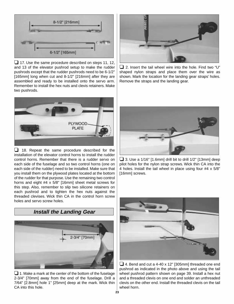
❏ 17. Use the same procedure described on steps 11, 12,and 13 of the elevator pushrod setup to make the rudderpushrods except that the rudder pushrods need to be 6-1/2"[165mm] long when cut and 8-1/2" [216mm] after they areassembled and ready to be installed onto the servo arm.Remember to install the hex nuts and clevis retainers. Maketwo pushrods.
❏ 18. Repeat the same procedure described for theinstallation of the elevator control horns to install the ruddercontrol horns. Remember that there is a rudder servo oneach side of the fuselage and so two control horns (one oneach side of the rudder) need to be installed. Make sure thatyou install them on the plywood plates located at the bottomof the rudder for that purpose. Use the remaining two controlhorns and eight #4 x 5/8" [16mm] sheet metal screws forthis step. Also, remember to slip two silicone retainers oneach pushrod and to tighten the hex nuts against thethreaded clevises. Wick thin CA in the control horn screwholes and servo screw holes.
❏ 1. Make a mark at the center of the bottom of the fuselage2-3/4" [70mm] away from the end of the fuselage. Drill a7/64" [2.8mm] hole 1" [25mm] deep at the mark. Wick thinCA into this hole.
❏ 2. Insert the tail wheel wire into the hole. Find two “U”shaped nylon straps and place them over the wire asshown. Mark the location for the landing gear straps’ holes.Remove the straps and the landing gear.
❏ 3. Use a 1/16" [1.6mm] drill bit to drill 1/2" [13mm] deeppilot holes for the nylon strap screws. Wick thin CA into the4 holes. Install the tail wheel in place using four #4 x 5/8"[16mm] screws.
❏ 4. Bend and cut a 4-40 x 12" [305mm] threaded one endpushrod as indicated in the photo above and using the tailwheel pushrod pattern shown on page 39. Install a hex nutand a threaded clevis on one end and solder an unthreadedclevis on the other end. Install the threaded clevis on the tailwheel horn.
Install the Landing Gear
23
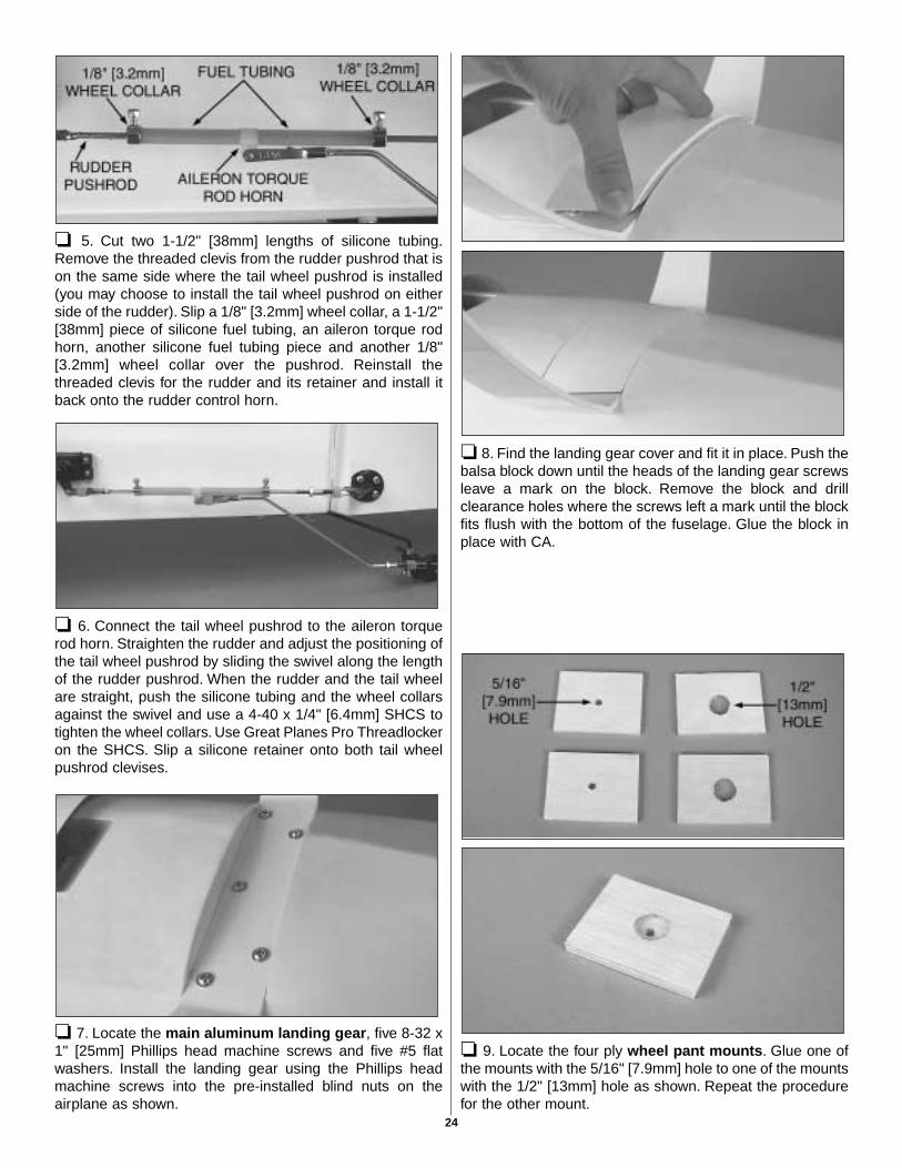
❏ 5. Cut two 1-1/2" [38mm] lengths of silicone tubing.Remove the threaded clevis from the rudder pushrod that ison the same side where the tail wheel pushrod is installed(you may choose to install the tail wheel pushrod on eitherside of the rudder). Slip a 1/8" [3.2mm] wheel collar, a 1-1/2"[38mm] piece of silicone fuel tubing, an aileron torque rodhorn, another silicone fuel tubing piece and another 1/8"[3.2mm] wheel collar over the pushrod. Reinstall thethreaded clevis for the rudder and its retainer and install itback onto the rudder control horn.
❏ 6. Connect the tail wheel pushrod to the aileron torquerod horn. Straighten the rudder and adjust the positioning ofthe tail wheel pushrod by sliding the swivel along the lengthof the rudder pushrod. When the rudder and the tail wheelare straight, push the silicone tubing and the wheel collarsagainst the swivel and use a 4-40 x 1/4" [6.4mm] SHCS totighten the wheel collars. Use Great Planes Pro Threadlockeron the SHCS. Slip a silicone retainer onto both tail wheelpushrod clevises.
❏ 7. Locate the main aluminum landing gear, five 8-32 x1" [25mm] Phillips head machine screws and five #5 flatwashers. Install the landing gear using the Phillips headmachine screws into the pre-installed blind nuts on theairplane as shown.
❏ 8. Find the landing gear cover and fit it in place. Push thebalsa block down until the heads of the landing gear screwsleave a mark on the block. Remove the block and drillclearance holes where the screws left a mark until the blockfits flush with the bottom of the fuselage. Glue the block inplace with CA.
❏ 9. Locate the four ply wheel pant mounts. Glue one ofthe mounts with the 5/16" [7.9mm] hole to one of the mountswith the 1/2" [13mm] hole as shown. Repeat the procedurefor the other mount.
24
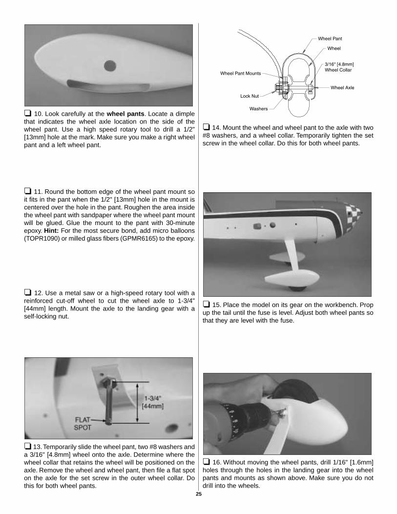
❏ 10. Look carefully at the wheel pants. Locate a dimplethat indicates the wheel axle location on the side of thewheel pant. Use a high speed rotary tool to drill a 1/2"[13mm] hole at the mark. Make sure you make a right wheelpant and a left wheel pant.
❏ 11. Round the bottom edge of the wheel pant mount soit fits in the pant when the 1/2" [13mm] hole in the mount iscentered over the hole in the pant. Roughen the area insidethe wheel pant with sandpaper where the wheel pant mountwill be glued. Glue the mount to the pant with 30-minuteepoxy. Hint: For the most secure bond, add micro balloons(TOPR1090) or milled glass fibers (GPMR6165) to the epoxy.
❏ 12. Use a metal saw or a high-speed rotary tool with areinforced cut-off wheel to cut the wheel axle to 1-3/4"[44mm] length. Mount the axle to the landing gear with aself-locking nut.
❏ 13.Temporarily slide the wheel pant, two #8 washers anda 3/16" [4.8mm] wheel onto the axle. Determine where thewheel collar that retains the wheel will be positioned on theaxle. Remove the wheel and wheel pant, then file a flat spoton the axle for the set screw in the outer wheel collar. Dothis for both wheel pants.
❏ 14. Mount the wheel and wheel pant to the axle with two#8 washers, and a wheel collar. Temporarily tighten the setscrew in the wheel collar. Do this for both wheel pants.
❏ 15. Place the model on its gear on the workbench. Propup the tail until the fuse is level. Adjust both wheel pants sothat they are level with the fuse.
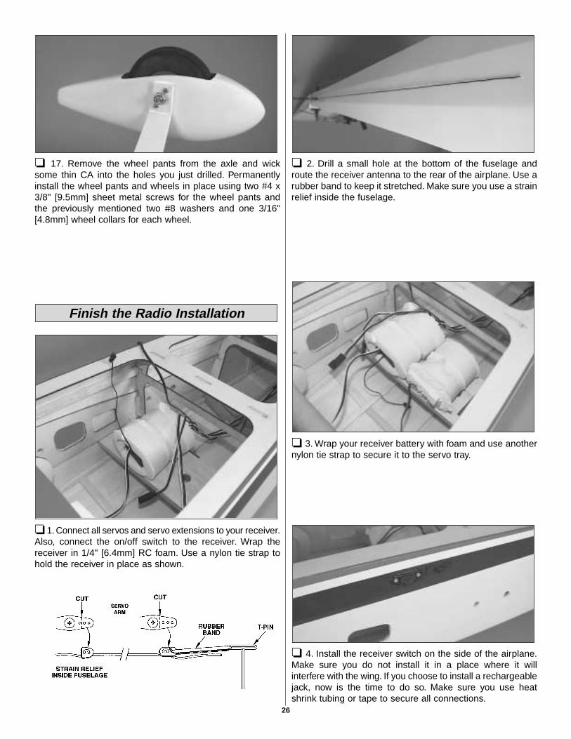
❏ 16. Without moving the wheel pants, drill 1/16" [1.6mm]holes through the holes in the landing gear into the wheelpants and mounts as shown above. Make sure you do notdrill into the wheels.
25
❏ 17. Remove the wheel pants from the axle and wicksome thin CA into the holes you just drilled. Permanentlyinstall the wheel pants and wheels in place using two #4 x3/8" [9.5mm] sheet metal screws for the wheel pants andthe previously mentioned two #8 washers and one 3/16"[4.8mm] wheel collars for each wheel.
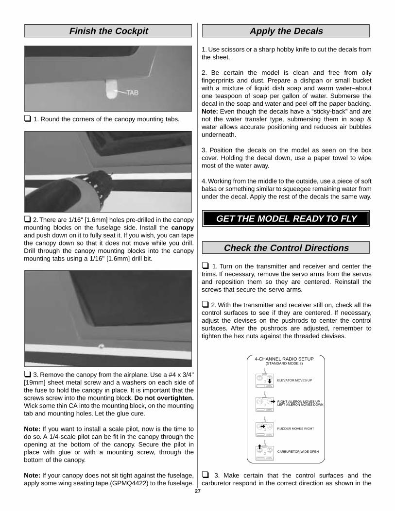
❏ 1. Connect all servos and servo extensions to your receiver.Also, connect the on/off switch to the receiver. Wrap thereceiver in 1/4" [6.4mm] RC foam. Use a nylon tie strap tohold the receiver in place as shown.
❏ 2. Drill a small hole at the bottom of the fuselage androute the receiver antenna to the rear of the airplane. Use arubber band to keep it stretched. Make sure you use a strainrelief inside the fuselage.
❏ 3. Wrap your receiver battery with foam and use anothernylon tie strap to secure it to the servo tray.
❏ 4. Install the receiver switch on the side of the airplane.Make sure you do not install it in a place where it willinterfere with the wing. If you choose to install a rechargeablejack, now is the time to do so. Make sure you use heatshrink tubing or tape to secure all connections.
Finish the Radio Installation
26
❏ 1. Round the corners of the canopy mounting tabs.
❏ 2. There are 1/16" [1.6mm] holes pre-drilled in the canopymounting blocks on the fuselage side. Install the canopyand push down on it to fully seat it. If you wish, you can tapethe canopy down so that it does not move while you drill.Drill through the canopy mounting blocks into the canopymounting tabs using a 1/16" [1.6mm] drill bit.
❏ 3. Remove the canopy from the airplane. Use a #4 x 3/4"[19mm] sheet metal screw and a washers on each side ofthe fuse to hold the canopy in place. It is important that thescrews screw into the mounting block. Do not overtighten.Wick some thin CA into the mounting block, on the mountingtab and mounting holes. Let the glue cure.
Note: If you want to install a scale pilot, now is the time todo so. A 1/4-scale pilot can be fit in the canopy through theopening at the bottom of the canopy. Secure the pilot inplace with glue or with a mounting screw, through thebottom of the canopy.
Note: If your canopy does not sit tight against the fuselage,apply some wing seating tape (GPMQ4422) to the fuselage.
1. Use scissors or a sharp hobby knife to cut the decals fromthe sheet.
2. Be certain the model is clean and free from oilyfingerprints and dust. Prepare a dishpan or small bucketwith a mixture of liquid dish soap and warm water–aboutone teaspoon of soap per gallon of water. Submerse thedecal in the soap and water and peel off the paper backing.Note: Even though the decals have a “sticky-back” and arenot the water transfer type, submersing them in soap &water allows accurate positioning and reduces air bubblesunderneath.
3. Position the decals on the model as seen on the boxcover. Holding the decal down, use a paper towel to wipemost of the water away.
4. Working from the middle to the outside, use a piece of softbalsa or something similar to squeegee remaining water fromunder the decal. Apply the rest of the decals the same way.
❏ 1. Turn on the transmitter and receiver and center thetrims. If necessary, remove the servo arms from the servosand reposition them so they are centered. Reinstall thescrews that secure the servo arms.
❏ 2. With the transmitter and receiver still on, check all thecontrol surfaces to see if they are centered. If necessary,adjust the clevises on the pushrods to center the controlsurfaces. After the pushrods are adjusted, remember totighten the hex nuts against the threaded clevises.
❏ 3. Make certain that the control surfaces and thecarburetor respond in the correct direction as shown in the
CARBURETOR WIDE OPEN
RUDDER MOVES RIGHT
LEFT AILERON MOVES DOWNRIGHT AILERON MOVES UP
ELEVATOR MOVES UP
4-CHANNELTRANSMITTER
(STANDARD MODE 2)4-CHANNEL RADIO SETUP
TRANSMITTER4-CHANNEL
TRANSMITTER4-CHANNEL
TRANSMITTER4-CHANNEL
Check the Control Directions
GET THE MODEL READY TO FLY
Apply the DecalsFinish the Cockpit
27
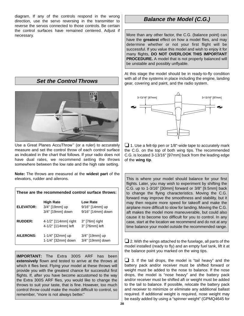
diagram. If any of the controls respond in the wrongdirection, use the servo reversing in the transmitter toreverse the servos connected to those controls. Be certainthe control surfaces have remained centered. Adjust ifnecessary.
Use a Great Planes AccuThrow™ (or a ruler) to accuratelymeasure and set the control throw of each control surfaceas indicated in the chart that follows. If your radio does nothave dual rates, we recommend setting the throwssomewhere between the low rate and the high rate setting.
Note: The throws are measured at the widest part of theelevators, rudder and ailerons.
At this stage the model should be in ready-to-fly conditionwith all of the systems in place including the engine, landinggear, covering and paint, and the radio system.
❏ 1. Use a felt-tip pen or 1/8"-wide tape to accurately markthe C.G. on the top of both wing tips. The recommendedC.G. is located 3-13/16" [97mm] back from the leading edgeof the wing tip.
❏ 2. With the wings attached to the fuselage, all parts of themodel installed (ready to fly) and an empty fuel tank, lift it atthe balance point you marked on the wing tips.
❏ 3. If the tail drops, the model is “tail heavy” and thebattery pack and/or receiver must be shifted forward orweight must be added to the nose to balance. If the nosedrops, the model is “nose heavy” and the battery packand/or receiver must be shifted aft or weight must be addedto the tail to balance. If possible, relocate the battery packand receiver to minimize or eliminate any additional ballastrequired. If additional weight is required, nose weight maybe easily added by using a “spinner weight” (GPMQ4645 for
This is where your model should balance for your firstflights. Later, you may wish to experiment by shifting theC.G. up to 1-3/16" [30mm] forward or 3/8" [9.5mm] backto change the flying characteristics. Moving the C.G.forward may improve the smoothness and stability, but itmay then require more speed for takeoff and make theairplane more difficult to slow for landing. Moving the C.G.aft makes the model more maneuverable, but could alsocause it to become too difficult for you to control. In anycase, start at the location we recommend and do not at anytime balance your model outside the recommended range.
More than any other factor, the C.G. (balance point) canhave the greatest effect on how a model flies, and maydetermine whether or not your first flight will besuccessful. If you value this model and wish to enjoy it formany flights, DO NOT OVERLOOK THIS IMPORTANTPROCEDURE. A model that is not properly balanced willbe unstable and possibly unflyable.
Balance the Model (C.G.)
IMPORTANT: The Extra 300S ARF has beenextensively flown and tested to arrive at the throws atwhich it flies best. Flying your model at these throws willprovide you with the greatest chance for successful firstflights. If, after you have become accustomed to the waythe Extra 300S ARF flies, you would like to change thethrows to suit your taste, that is fine. However, too muchcontrol throw could make the model difficult to control, soremember, “more is not always better.”
These are the recommended control surface throws:
High Rate Low RateELEVATOR: 3/4" [19mm] up 9/16" [14mm] up
3/4" [19mm] down 9/16" [14mm] down
RUDDER: 4-1/2" [114mm] right 3" [76m] right4-1/2" [114mm] left 3" [76mm] left
AILERONS: 1-1/4" [32mm] up 3/4" [19mm] up1-1/4" [32mm] down 3/4" [19mm] down
Set the Control Throws
28
the 1 oz. weight, or GPMQ4646 for the 2 oz. weight). Ifspinner weight is not practical or is not enough, use GreatPlanes (GPMQ4485) “stick-on” lead. A good place to addstick-on nose weight is to the firewall (don’t attach weight tothe cowl–it is not intended to support weight). Begin byplacing incrementally increasing amounts of weight on thebottom of the fuse over the firewall until the model balances.Once you have determined the amount of weight required,it can be permanently attached. If required, tail weight maybe added by cutting open the bottom of the fuse and gluingit permanently inside.
Note: Do not rely upon the adhesive on the back of the leadweight to permanently hold it in place. Over time, fuel andexhaust residue may soften the adhesive and cause theweight to fall off. Use #2 sheet metal screws, RTV siliconeor epoxy to permanently hold the weight in place.
❏ 4. IMPORTANT: If you found it necessary to add anyweight, recheck the C.G. after the weight has been installed.
❏ 1. With the wing level, have an assistant help you lift themodel by the engine propeller shaft and the bottom of thefuse under the TE of the fin. Do this several times.
❏ 2. If one wing always drops when you lift the model, itmeans that side is heavy. Balance the airplane by addingweight to the other wing tip. An airplane that has beenlaterally balanced will track better in loops and othermaneuvers.
No matter if you fly at an AMA sanctioned R/C club site or ifyou fly somewhere on your own, you should always haveyour name, address, telephone number and AMA numberon or inside your model. It is required at all AMA R/C clubflying sites and AMA sanctioned flying events. Fill out theidentification tag in page 35 of this manual and place it onor inside your model.
Follow the battery charging instructions that came with yourradio control system to charge the batteries. You shouldalways charge your transmitter and receiver batteries thenight before you go flying, and at other times asrecommended by the radio manufacturer.
Note: Checking the condition of your receiver battery packis highly recommended. All battery packs, whether it’s a
trusty pack you’ve just taken out of another model, or a newbattery pack you just purchased, should be cycled, notingthe discharge capacity. Oftentimes, a weak battery pack canbe identified (and a valuable model saved!) by comparing itsactual capacity to its rated capacity. Refer to the instructionsand recommendations that come with your cycler. If youdon’t own a battery cycler, perhaps you can have a friendcycle your pack and note the capacity for you.
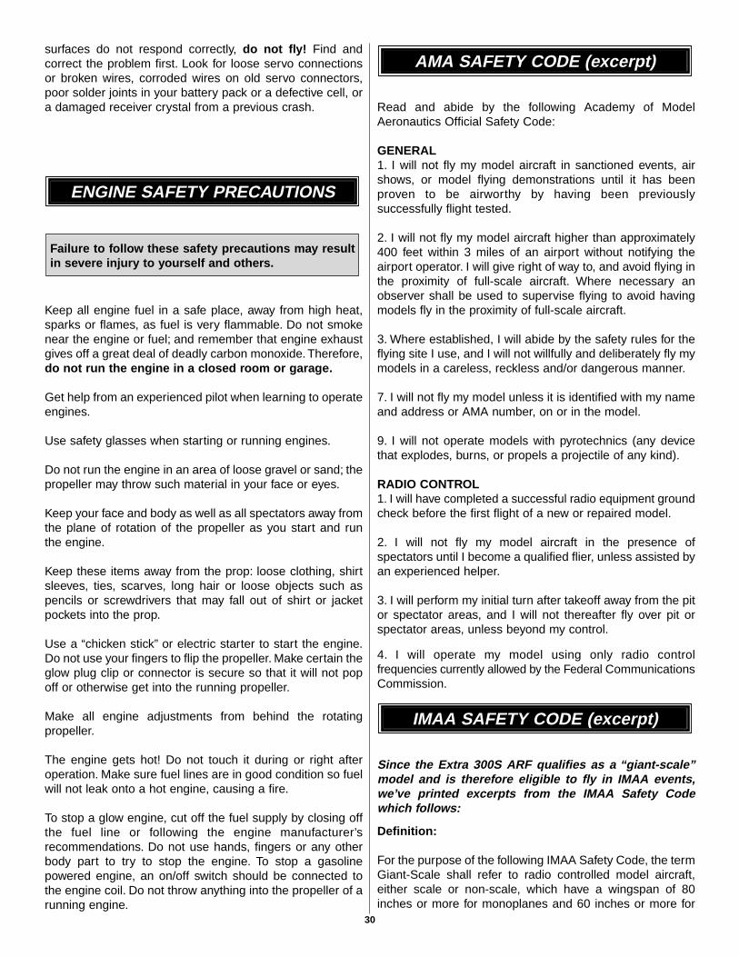
Carefully balance your propeller and spare propellers beforeyou fly. An unbalanced prop can be the single mostsignificant cause of vibration that can damage your model.Not only will engine mounting screws and bolts loosen,possibly with disastrous effect, but vibration may alsodamage your radio receiver and battery. Vibration can alsocause your fuel to foam, which will, in turn, cause yourengine to run hot or quit.
We use a Top Flite Precision Magnetic Prop Balancer™
(TOPQ5700) in the workshop and keep a Great PlanesFingertip Prop Balancer (GPMQ5000) in our flight box.
If the engine is new, follow the engine manufacturer’sinstructions to break-in the engine. After break-in,confirm that the engine idles reliably, transitions smoothlyand rapidly to full power and maintains fullpower–indefinitely. After you run the engine on the model,inspect the model closely to make sure all screws remainedtight, the hinges are secure, the prop is secure and allpushrods and connectors are secure.
Ground check the operational range of your radio before thefirst flight of the day. With the transmitter antenna collapsedand the receiver and transmitter on, you should be able towalk at least 100 feet away from the model and still havecontrol. Have an assistant stand by your model and, whileyou work the controls, tell you what the control surfaces aredoing. Repeat this test with the engine running at variousspeeds with an assistant holding the model, using handsignals to show you what is happening. If the control
Range Check
Ground Check
Balance the Propellers
Charge the Batteries
Identify Your Model
PREFLIGHT
Balance the Model Laterally
29
surfaces do not respond correctly, do not fly! Find andcorrect the problem first. Look for loose servo connectionsor broken wires, corroded wires on old servo connectors,poor solder joints in your battery pack or a defective cell, ora damaged receiver crystal from a previous crash.
Keep all engine fuel in a safe place, away from high heat,sparks or flames, as fuel is very flammable. Do not smokenear the engine or fuel; and remember that engine exhaustgives off a great deal of deadly carbon monoxide. Therefore,do not run the engine in a closed room or garage.
Get help from an experienced pilot when learning to operateengines.
Use safety glasses when starting or running engines.
Do not run the engine in an area of loose gravel or sand; thepropeller may throw such material in your face or eyes.
Keep your face and body as well as all spectators away fromthe plane of rotation of the propeller as you start and runthe engine.
Keep these items away from the prop: loose clothing, shirtsleeves, ties, scarves, long hair or loose objects such aspencils or screwdrivers that may fall out of shirt or jacketpockets into the prop.
Use a “chicken stick” or electric starter to start the engine.Do not use your fingers to flip the propeller. Make certain theglow plug clip or connector is secure so that it will not popoff or otherwise get into the running propeller.
Make all engine adjustments from behind the rotatingpropeller.
The engine gets hot! Do not touch it during or right afteroperation. Make sure fuel lines are in good condition so fuelwill not leak onto a hot engine, causing a fire.
To stop a glow engine, cut off the fuel supply by closing offthe fuel line or following the engine manufacturer’srecommendations. Do not use hands, fingers or any otherbody part to try to stop the engine. To stop a gasolinepowered engine, an on/off switch should be connected tothe engine coil. Do not throw anything into the propeller of arunning engine.
Read and abide by the following Academy of ModelAeronautics Official Safety Code:
GENERAL1. I will not fly my model aircraft in sanctioned events, airshows, or model flying demonstrations until it has beenproven to be airworthy by having been previouslysuccessfully flight tested.
2. I will not fly my model aircraft higher than approximately400 feet within 3 miles of an airport without notifying theairport operator. I will give right of way to, and avoid flying inthe proximity of full-scale aircraft. Where necessary anobserver shall be used to supervise flying to avoid havingmodels fly in the proximity of full-scale aircraft.
3. Where established, I will abide by the safety rules for theflying site I use, and I will not willfully and deliberately fly mymodels in a careless, reckless and/or dangerous manner.
7. I will not fly my model unless it is identified with my nameand address or AMA number, on or in the model.
9. I will not operate models with pyrotechnics (any devicethat explodes, burns, or propels a projectile of any kind).
RADIO CONTROL1. I will have completed a successful radio equipment groundcheck before the first flight of a new or repaired model.
2. I will not fly my model aircraft in the presence ofspectators until I become a qualified flier, unless assisted byan experienced helper.
3. I will perform my initial turn after takeoff away from the pitor spectator areas, and I will not thereafter fly over pit orspectator areas, unless beyond my control.
4. I will operate my model using only radio controlfrequencies currently allowed by the Federal CommunicationsCommission.
Since the Extra 300S ARF qualifies as a “giant-scale”model and is therefore eligible to fly in IMAA events,we’ve printed excerpts from the IMAA Safety Codewhich follows:
Definition:
For the purpose of the following IMAA Safety Code, the termGiant-Scale shall refer to radio controlled model aircraft,either scale or non-scale, which have a wingspan of 80inches or more for monoplanes and 60 inches or more for
IMAA SAFETY CODE (excerpt)
AMA SAFETY CODE (excerpt)
Failure to follow these safety precautions may resultin severe injury to yourself and others.
ENGINE SAFETY PRECAUTIONS
30
multi-winged model aircraft and have a ramp weight (fueledand ready to fly) of 55 lbs. or less.
Section 1.0: SAFETY STANDARD
1.1 – Adherence to Code: This safety code is to be strictlyfollowed.
1.2 The most current AMA Safety Code in effect is to beobserved. However, the competition sections of the codemay be disregarded.
Section 3.0: Safety Check
3.4 – Flight Testing: All Giant-Scale R/C aircraft are to havebeen flight tested and flight trimmed with a minimum of sixflights before the model is allowed to fly at an IMAASanctioned event.
3.5 – Proof of Flight: The completing and signing of theDeclaration section of the Safety Inspection form by the pilot(or owner) shall document as fact that each aircraft hasbeen successfully flight-tested and proven airworthy prior toan IMAA event.
Section 5.0: EMERGENCY ENGINE SHUT OFF (kill switch)
5.1 All magneto spark ignition engines must have a coilgrounding switch on the aircraft to stop the engine. This willalso prevent accidental starting of the engine. This switchshall be readily available to both pilot and helper. This switchis to be operated manually and without the use of the radiosystem.
5.2 Engines with battery power ignition systems must havea switch to turn off the power from the battery pack todisable the engine from firing. This will also preventaccidental starting of the engine. This switch shall be readilyavailable to both pilot and helper. This switch shall beoperated manually and without the use of the RadioSystem.
5.3 There must also be a means to stop the engine from thetransmitter. The most common method is to close thecarburetor throat completely using throttle trim. However,other methods are acceptable. This requirement applies toall glow/gas ignition engines regardless of size.
Section 6.0: RADIO REQUIREMENTS
6.1 All transmitters must be FCC type certified.
6.2 FCC Technician or higher-class license required for 6meter band operation only.
Additional IMAA General Recommendations
The following recommendations are included in the SafetyCode not to police such items, but rather to offer basicsuggestions for enhanced safety.
Servos need to be of a rating capable to handle the loadsthat the control surfaces impose upon the servos. Standardservos are not recommended for control surfaces. Servosshould be rated heavy-duty. For flight-critical controlfunctions a minimum of 45 inch/ounces of torque should beconsidered. This should be considered a minimum forsmaller aircraft and higher torque servos are stronglyencouraged for larger aircraft. The use of one servo for eachaileron and one for each elevator half is stronglyrecommended. Use of dual servos is also recommended forlarger aircraft.
On-board batteries shall be 1000 mAh up to 20 lbs., 1200mAh to 30 lbs., 1800 mAh to 40 lbs., and 2000 mAh over 40lbs. flying weight. The number and size of servos, size andloads on control surfaces, and added features should beconsidered as an increase to these minimums. Batteriesshould be able to sustain power to the onboard radiocomponents for a minimum of one hour total flying timebefore recharging.
Redundant and fail-safe battery systems are recommended.
The use of anti-glitch devices for long leads are recommended.
There is no maximum engine displacement limit, as it is theposition of this body that an underpowered aircraft presentsa greater danger than an overpowered aircraft. However, theselection of engine size relative to airframe strength andpower loading mandates good discretionary judgment bythe designer and builder. Current AMA maximums forengine displacement are 6.0 cu. in. for two-stroke and 9.6cu. in. for four-stroke engines. These maximums apply onlyto AMA Sanctions concerning competition events (such as511, 512, 515 and 520) and, as such, the maximums apply.All IMAA (non competition) events should be sanctioned asClass “C” events, in which these engine size maximums donot apply.
Generally, it is recommended that no attempt should bemade to fly a radio controlled model aircraft with a gasolineengine in which the model aircraft weight would exceedtwelve (12) pounds (underpowered) per cubic inch of enginedisplacement, or be less than five (5) pounds (overpowered)per cubic inch of engine displacement. Example: Using a 3cu. in. engine, a model would likely be underpowered at anaircraft weight greater than 36 pounds. With the sameengine, an aircraft weighing less than 15 pounds wouldlikely be overpowered.
Servo arms and wheels should be rated heavy-duty. Glass-filled servo arms and control horns are highly recommended.
Control surfaces linkages are listed in order of preference:
1. Cable system (pull-pull). A tiller bar is highly recommendedalong with necessary bracing.
2. Arrow Shaft, fiberglass or aluminum, 1/4" or 5/16" O.D.bracing every six (6) to ten (10) inches is highlyrecommended.
31
3. Tube-in-tube (nyrod). Bracing every few inches is highlyrecommended. Inner tube should be totally enclosed inouter tube.
4. Hardwood dowel, 3/8" O.D. bracing every six (6) to ten(10) inches is highly recommended.
Hinges should be rated heavy-duty and manufactured forGiant-Scale use primarily. Homemade and original designhinges are acceptable if determined to be adequate for theintended use.
Clevis (steel, excluding heavy-duty ball links) andattachment hardware should be heavy-duty 4-40 threadedrod type. 2-56 threaded size rod is acceptable for someapplications (e.g. throttle). Clevis is to have lock nuts andsleeve or spring keepers.
Propeller tips should be painted or colored in a visible andcontrasting manner so as to increase the visibility of thepropeller tip arc.
❏ 1. Fuelproof all areas exposed to fuel or exhaustresidue such as the wing saddle area or the enginespacer if needed.
❏ 2. Check the C.G. according to the measurementsprovided in the manual.
❏ 3. Be certain the battery and receiver are securelymounted in the fuse. Simply stuffing them into placewith foam rubber is not sufficient.
❏ 4 Extend your receiver antenna and make sure it hasa strain relief inside the fuselage to keep tension offthe solder joint inside the receiver.
❏ 5. Balance your model laterally as explained in theinstructions.
❏ 6. Use thread locking compound to secure criticalfasteners such as the screws that hold thecarburetor arm (if applicable), Screw-Lock pushrodconnectors, etc.
❏ 7. Add a drop of oil to the axles so the wheels willturn freely.
❏ 8. Make sure all hinges are securely glued in place.❏ 9. Reinforce holes for wood screws with thin CA
where appropriate (servo mounting screws, cowlmounting screws, etc.).
❏ 10. Confirm that all controls operate in the correctdirection and the throws are set up according tothe manual.
❏ 11. Make sure there are silicone retainers on all theclevises and that all servo arms are secured to theservos with the screws included with your radio.
❏ 12. Secure the connections between servo wires and Y-connectors or servo extensions, and theconnection between your battery pack and theon/off switch with vinyl tape, heat shrink tubing orspecial clips suitable for that purpose.
❏ 13. Make sure any servo extension cords you may haveused do not interfere with other systems (servoarms, pushrods, etc.).
❏ 14. Make sure the fuel lines are connected and arenot kinked.
❏ 15 Balance your propeller (and spare propellers).❏ 16. Tighten the propeller nut and spinner.❏ 17. Place your name, address, AMA number and
telephone number on or inside your model.❏ 18. Cycle your receiver battery pack (if necessary) and
make sure it is fully charged.❏ 19. If you wish to photograph your model, do so before
your first flight.❏ 20. Range check your radio when you get to the flying field.
The Extra 300S ARF is a great-flying model that fliessmoothly and predictably. The Extra 300S ARF does not,however, possess the self-recovery characteristics of aprimary R/C trainer and should be flown only beexperienced R/C pilots.
A fully cowled engine may run at a higher temperature thanan un-cowled engine. For this reason, the fuel mixtureshould be richened so the engine runs at about 200 rpmbelow peak speed. By running the engine slightly rich, youwill help prevent dead-stick landings caused by overheating.
Fuel Mixture Adjustments
FLYING
During the last few moments of preparation your mindmay be elsewhere anticipating the excitement of the firstflight. Because of this, you may be more likely to overlookcertain checks and procedures that should be performedbefore the model is flown. To help avoid this, a check listis provided to make sure these important areas are notoverlooked. Many are covered in the instruction manual,so where appropriate, and refer to the manual forcomplete instructions. Be sure to check the items off asthey are completed (that’s why it’s called a check list!).
CHECK LIST
32
Before you get ready to takeoff, see how the model handleson the ground by doing a few practice runs at low speedson the runway. Hold “up” elevator to keep the tail wheel onthe ground. If necessary, adjust the tail wheel so the modelwill roll straight down the runway. If you need to calm yournerves before the maiden flight, shut the engine down andbring the model back into the pits. Top off the fuel, thencheck all fasteners and control linkages for peace of mind.
Remember to takeoff into the wind. When you’re ready, pointthe model straight down the runway, hold a bit of up elevatorto keep the tail on the ground to maintain tail wheel steering,and then gradually advance the throttle. As the model gainsspeed, decrease up elevator allowing the tail to come off theground. One of the most important things to remember witha tail dragger is to always be ready to apply right rudder tocounteract engine torque. Gain as much speed as yourrunway and flying site will practically allow before gentlyapplying up elevator, lifting the model into the air. At thismoment it is likely that you will need to apply more rightrudder to counteract engine torque. Be smooth on theelevator stick, allowing the model to establish a gentle climbto a safe altitude before turning into the traffic pattern.
For reassurance and to keep an eye on other traffic, it is agood idea to have an assistant on the flight line with you.Tellhim to remind you to throttle back once the plane gets to acomfortable altitude.While full throttle is usually desirable fortakeoff, most models fly more smoothly at reduced speeds.
Take it easy with the Extra 300S ARF for the first few flights,gradually getting acquainted with it as you gain confidence.
Adjust the trims to maintain straight and level flight. Afterflying around for a while, and while still at a safe altitude withplenty of fuel, practice slow flight and execute practicelanding approaches by reducing the throttle to see how themodel handles at slower speeds. Add power to see how sheclimbs as well. Continue to fly around, executing variousmaneuvers and making mental notes (or having yourassistant write them down) of what trim or C.G. changesmay be required to fine tune the model so it flies the way youlike. Mind your fuel level, but use this first flight to becomefamiliar with your model before landing.
To initiate a landing approach, lower the throttle while on thedownwind leg. Allow the nose of the model to pitchdownward to gradually bleed off altitude. Continue to losealtitude, but maintain airspeed by keeping the nose down asyou turn onto the crosswind leg. Make your final turn towardthe runway (into the wind) keeping the nose down tomaintain airspeed and control. Level the attitude when themodel reaches the runway threshold, modulating the throttleas necessary to maintain your glide path and airspeed. Ifyou are going to overshoot, smoothly advance the throttle(always ready on the right rudder to counteract torque) andclimb out to make another attempt. When you’re ready tomake your landing flare and the model is a foot or so off thedeck, smoothly increase up elevator until it gently touchesdown. Once the model is on the runway and has lost flyingspeed, hold up elevator to place the tail on the ground,regaining tail wheel control.
One final note about flying your model. Have a goal or flightplan in mind for every flight. This can be learning a newmaneuver(s), improving a maneuver(s) you already know, orlearning how the model behaves in certain conditions (suchas on high or low rates). This is not necessarily to improveyour skills (though it is never a bad idea!), but moreimportantly so you do not surprise yourself by impulsivelyattempting a maneuver and suddenly finding that you’ve runout of time, altitude or airspeed. Every maneuver should bedeliberate, not impulsive. For example, if you’re going to doa loop, check your altitude, mind the wind direction(anticipating rudder corrections that will be required tomaintain heading), remember to throttle back at the top, andmake certain you are on the desired rates (high/low rates).A flight plan greatly reduces the chances of crashing yourmodel just because of poor planning and impulsive moves.Remember to think.
The Extra 300S ARF will perform 3-D aerobatics easily ifyou use the larger engines recommended within the enginerange. If you setup your airplane to do 3D maneuvers, you
Performance Settings for theExtra 300S ARF
Landing
Flight
Takeoff
CAUTION (THIS APPLIES TO ALL R/C AIRPLANES): If,while flying, you notice any unusual sounds, such as alow-pitched “buzz,” this may indicate control surfaceflutter. Because flutter can quickly destroy components ofyour airplane, any time you detect flutter you mustimmediately cut the throttle and land the airplane! Checkall servo grommets for deterioration (this may indicatewhich surface fluttered), and make sure all pushrodlinkages are secure and free of play. If the control surfacefluttered once, it probably will flutter again under similarcircumstances unless you can eliminate the free-play orflexing in the linkages. Here are some things which cancause flutter: Excessive hinge gap; Not mounting controlhorns solidly; Poor fit of clevis pin in horn; Side-play ofpushrod in guide tube caused by tight bends; Poor fit ofZ-bend in servo arm; Insufficient glue used when gluing inthe elevator joiner wire; Excessive play or backlash inservo gears; and Insecure servo mounting.
33
will need to be throttle conscious; that is, never apply fullthrottle on straight and level flying or in dives to preventflutter.
The large control throws require servos with great centering.The digital servos are second to none in this department.Digital servos such as the Futaba S9250 (FUTM0220)should be used on all control surfaces of this airplane foroptimum performance. The test models were also flownsuccessfully in 3D mode with analog Futaba S9304(FUTM0095) servos.
Have a ball! But always stay in control and fly in a safemanner.
GOOD LUCK AND GREAT FLYING!
Why only adjust ATV slightly? Control linkages arereally just a lesson in leverage. The less distance theservo is moving for a given throw at the surface, the lessleverage you have given the servo to do the job. Thusthe lower you set the ATV the less power you areleaving for the servo to apply to the surface. Additionally,a servo has only so many points within its range ofmotion. By cutting its range in half, you’ve alsodiminished the precision of the servo by 50%. Becauseof both of these issues, we strongly recommend settingthe high rates as close as possible to 100% on the ATV.
Dual Rates: Setting dual rates helps make your modeleasier to fly in a variety of situations. For example, anexpert pilot who wants to do torque rolls will need alarge amount of control throw. However, he does notwant that same huge volume of throw when he is tryingto do smooth loops or slow rolls. Low rates give yourmodel a soft feel, with aggressive responsiveness just aflip of a switch away.
Exponential, the best of both rates: Exponential is afeature which modelers tend to either love or hate. Thebenefits of exponential are that they make the elevator,for example, feel like it is on low rates when you aremoving the stick near center; however, when you getfarther from center the model gets progressively moreresponsive. The reason this is helpful is that it allowsyou to make soft, minor adjustments when smallcorrections are needed, but still allows you sufficientthrow to make major changes at full stick. For example,you can smoothly level the wings while flying alongstraight and level without over-controlling, yet still haveenough aileron throw at full stick to complete a one-second roll.
Idle Down and Throttle Kill: Idle down allows you tohave a switch set for a high idle, ideal for mostaerobatics where you have little or no risk of deadsticking, as well as a lower idle setting for, say, landings,taxiing, and minimum throttle maneuvers such as spins.The throttle kill setting on most computer radios will idleyour engine down whatever percent you set it so thatyour engine will shut off when the switch is thrown andthe throttle stick is in the idle position. This is anexcellent safety feature to shut off your engine inemergency situations.
COMPUTER RADIOSAs you prepare to fly the Extra 300S ARF for the firsttime, there are a few features on computer radios we’dlike to mention. There are many others, of course, butthese are commonly used features on most computerradios. If you are using a non-computerized radio, thisinformation may still be of interest to you for futureinstallations.
ATV or Travel Volume: ATV is a wonderful feature ofcomputer radios which allows you to make minoradjustments to how far a servo travels at its extremes.For example, you install the throttle pushrod, and it’salmost perfect, except you have some binding at wideopen. Instead of struggling with the clevises to try tokeep full throttle but not have the binding, you can turndown the ATV slightly until the binding is gone.
Servos
Larger than stock servo arms are highly recommendedfor getting the 3D throws for the Extra 300S ARF. Do notmove the pushrods in on the control horns to get theincreased throw, as doing that intensifies any play in thesystem. Dubro Super Strength Arms sets (DUBM6670)were used on the test models.
3D Servo Arms
ELEVATOR: 3-1/4" [83mm] Up3-1/4" [83mm] Down
RUDDER: 6-1/2" [165mm] Right6-1/2" [165mm] Left
AILERONS: 1-3/4" [45mm] Up1-3/4" [45mm] Down
3D Control Throws
34
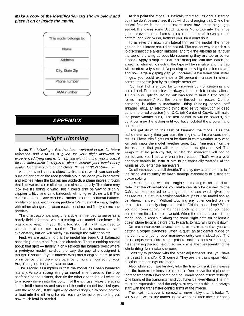
Make a copy of the identification tag shown below andplace it on or inside the model.
Note: The following article has been reprinted in part for futurereference and also as a guide for your flight instructor orexperienced flying partner to help you with trimming your model. Iffurther information is required, please contact your local hobbydealer, local flying club or call Great Planes at (217) 398-8970
A model is not a static object. Unlike a car, which you can onlyhunt left or right on the road (technically, a car does yaw in corners,and pitches when the brakes are applied), a plane moves throughthat fluid we call air in all directions simultaneously. The plane maylook like it’s going forward, but it could also be yawing slightly,slipping a little and simultaneously climbing or diving a bit! Thecontrols interact. Yaw can be a rudder problem, a lateral balanceproblem or an aileron rigging problem. We must make many flights,with minor changes between each, to isolate and finally correct theproblem.
The chart accompanying this article is intended to serve as ahandy field reference when trimming your model. Laminate it inplastic and keep it in your flight box. You just might have need toconsult it at the next contest! The chart is somewhat self-explanatory, but we will briefly run through the salient points.
First, we are assuming that the model has been C.G. balancedaccording to the manufacturer’s directions. There’s nothing sacredabout that spot — frankly, it only reflects the balance point wherea prototype model handled the way the guy who designed itthought it should. If your model’s wing has a degree more or lessof incidence, then the whole balance formula is incorrect for you.But, it’s a good ballpark place to start.
The second assumption is that the model has been balancedlaterally. Wrap a strong string or monofilament around the propshaft behind the spinner, then tie the other end to the tail wheel orto a screw driven into the bottom of the aft fuse. Make the stringinto a bridle harness and suspend the entire model inverted (yes,with the wing on!). If the right wing always drops, sink some screwsor lead into the left wing tip, etc. You may be surprised to find outhow much lead is needed.
At this point the model is statically trimmed. It’s only a startingpoint, so don’t be surprised if you wind up changing it all. One othercritical feature is that the ailerons must have their hinge gapsealed. If shoving some Scotch tape or MonoKote into the hingegap to prevent the air from slipping from the top of the wing to thebottom, and vice-versa, bothers you, then don’t do it.
To achieve the maximum lateral trim on the model, the hingegap on the ailerons should be sealed. The easiest way to do this isto disconnect the aileron linkages, and fold the ailerons as far overthe top of the wing as possible (assuming they are top or centerhinged). Apply a strip of clear tape along the joint line. When theaileron is returned to neutral, the tape will be invisible, and the gapwill be effectively sealed. Depending on how big the ailerons are,and how large a gaping gap you normally leave when you installhinges, you could experience a 20 percent increase in aileroncontrol response just by this simple measure.
Your first flights should be to ascertain control centering andcontrol feel. Does the elevator always come back to neutral after a180° turn or Split-S? Do the ailerons tend to hunt a little after arolling maneuver? Put the plane through its paces. Controlcentering is either a mechanical thing (binding servos, stifflinkages, etc.), an electronic thing (bad servo resolution or deadband in the radio system), or C.G. (aft Center of Gravity will makethe plane wander a bit). The last possibility will be obvious, butdon’t continue the testing until you have isolated the problem andcorrected it.
Let’s get down to the task of trimming the model. Use thetachometer every time you start the engine, to insure consistentresults. These trim flights must be done in calm weather. Any windwill only make the model weather vane. Each “maneuver” on thelist assumes that you will enter it dead straight-and-level. Thewings must be perfectly flat, or else the maneuver will not becorrect and you’ll get a wrong interpretation. That’s where yourobserver comes in. Instruct him to be especially watchful of thewings as you enter the maneuvers.
Do all maneuvers at full throttle. The only deviation from this is ifthe plane will routinely be flown through maneuvers at a differentpower setting.
Let’s commence with the “engine thrust angle” on the chart.Note that the observations you make can also be caused by theC.G., so be prepared to change both to see which gives thedesired result. Set up a straight-and-level pass. The model shouldbe almost hands-off. Without touching any other control on thetransmitter, suddenly chop the throttle. Did the nose drop? Whenyou add power again, did the nose pitch up a bit? If so, you needsome down thrust, or nose weight. When the thrust is correct, themodel should continue along the same flight path for at least adozen plane lengths before gravity starts to naturally bring it down.
Do each maneuver several times, to make sure that you aregetting a proper diagnosis. Often, a gust, an accidental nudge onthe controls, or just a poor maneuver entry can mislead you. Thethrust adjustments are a real pain to make. On most models, itmeans taking the engine out, adding shims, then reassembling thewhole thing. Don’t take shortcuts.
Don’t try to proceed with the other adjustments until you havethe thrust line and/or C.G. correct. They are the basis upon whichall other trim settings are made.
Also, while you have landed, take the time to crank the clevisesuntil the transmitter trims are at neutral. Don’t leave the airplane sothat the transmitter has some odd-ball combination of trim settings.One bump of the transmitter and you have lost everything. The trimmust be repeatable, and the only sure way to do this is to alwaysstart with the transmitter control trims at the middle.
The next maneuver is somewhat more tricky than it looks. Toverify C.G., we roll the model up to a 45° bank, then take our hands
Flight Trimming
APPENDIX
35
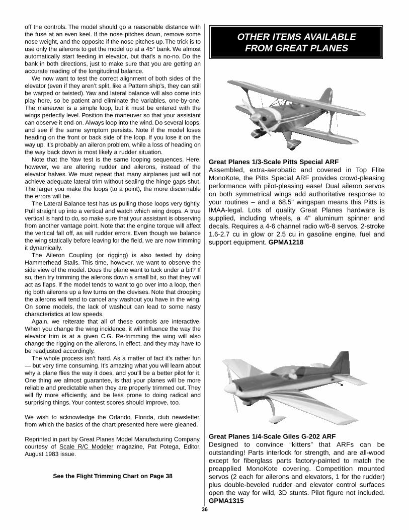
off the controls. The model should go a reasonable distance withthe fuse at an even keel. If the nose pitches down, remove somenose weight, and the opposite if the nose pitches up. The trick is touse only the ailerons to get the model up at a 45° bank. We almostautomatically start feeding in elevator, but that’s a no-no. Do thebank in both directions, just to make sure that you are getting anaccurate reading of the longitudinal balance.
We now want to test the correct alignment of both sides of theelevator (even if they aren’t split, like a Pattern ship’s, they can stillbe warped or twisted). Yaw and lateral balance will also come intoplay here, so be patient and eliminate the variables, one-by-one.The maneuver is a simple loop, but it must be entered with thewings perfectly level. Position the maneuver so that your assistantcan observe it end-on. Always loop into the wind. Do several loops,and see if the same symptom persists. Note if the model losesheading on the front or back side of the loop. If you lose it on theway up, it’s probably an aileron problem, while a loss of heading onthe way back down is most likely a rudder situation.
Note that the Yaw test is the same looping sequences. Here,however, we are altering rudder and ailerons, instead of theelevator halves. We must repeat that many airplanes just will notachieve adequate lateral trim without sealing the hinge gaps shut.The larger you make the loops (to a point), the more discernablethe errors will be.
The Lateral Balance test has us pulling those loops very tightly.Pull straight up into a vertical and watch which wing drops. A truevertical is hard to do, so make sure that your assistant is observingfrom another vantage point. Note that the engine torque will affectthe vertical fall off, as will rudder errors. Even though we balancethe wing statically before leaving for the field, we are now trimmingit dynamically.
The Aileron Coupling (or rigging) is also tested by doingHammerhead Stalls. This time, however, we want to observe theside view of the model. Does the plane want to tuck under a bit? Ifso, then try trimming the ailerons down a small bit, so that they willact as flaps. If the model tends to want to go over into a loop, thenrig both ailerons up a few turns on the clevises. Note that droopingthe ailerons will tend to cancel any washout you have in the wing.On some models, the lack of washout can lead to some nastycharacteristics at low speeds.
Again, we reiterate that all of these controls are interactive.When you change the wing incidence, it will influence the way theelevator trim is at a given C.G. Re-trimming the wing will alsochange the rigging on the ailerons, in effect, and they may have tobe readjusted accordingly.
The whole process isn’t hard. As a matter of fact it’s rather fun— but very time consuming. It’s amazing what you will learn aboutwhy a plane flies the way it does, and you’ll be a better pilot for it.One thing we almost guarantee, is that your planes will be morereliable and predictable when they are properly trimmed out. Theywill fly more efficiently, and be less prone to doing radical andsurprising things. Your contest scores should improve, too.
We wish to acknowledge the Orlando, Florida, club newsletter,from which the basics of the chart presented here were gleaned.
Reprinted in part by Great Planes Model Manufacturing Company,courtesy of Scale R/C Modeler magazine, Pat Potega, Editor,August 1983 issue.
See the Flight Trimming Chart on Page 38
Great Planes 1/3-Scale Pitts Special ARFAssembled, extra-aerobatic and covered in Top FliteMonoKote, the Pitts Special ARF provides crowd-pleasingperformance with pilot-pleasing ease! Dual aileron servoson both symmetrical wings add authoritative response toyour routines – and a 68.5" wingspan means this Pitts isIMAA-legal. Lots of quality Great Planes hardware issupplied, including wheels, a 4" aluminum spinner anddecals. Requires a 4-6 channel radio w/6-8 servos, 2-stroke1.6-2.7 cu in glow or 2.5 cu in gasoline engine, fuel andsupport equipment. GPMA1218
Great Planes 1/4-Scale Giles G-202 ARF Designed to convince “kitters” that ARFs can beoutstanding! Parts interlock for strength, and are all-woodexcept for fiberglass parts factory-painted to match thepreapplied MonoKote covering. Competition mountedservos (2 each for ailerons and elevators, 1 for the rudder)plus double-beveled rudder and elevator control surfacesopen the way for wild, 3D stunts. Pilot figure not included.GPMA1315
OTHER ITEMS AVAILABLEFROM GREAT PLANES
36
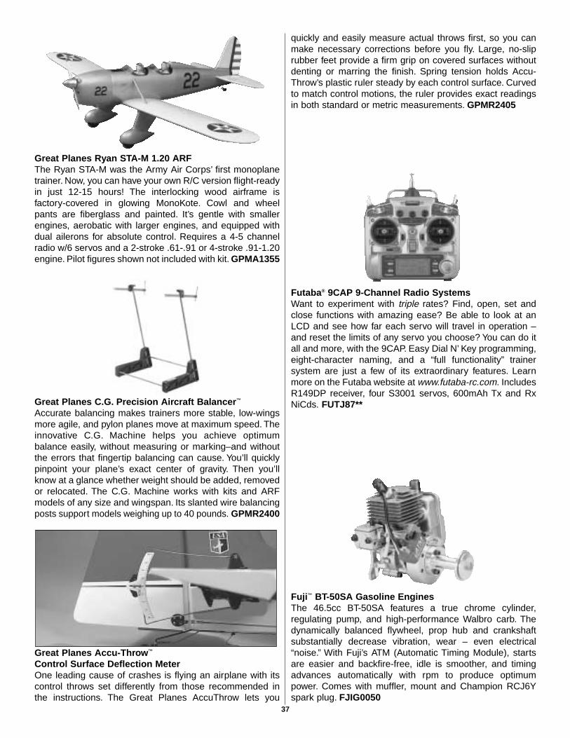
Great Planes Ryan STA-M 1.20 ARFThe Ryan STA-M was the Army Air Corps’ first monoplanetrainer. Now, you can have your own R/C version flight-readyin just 12-15 hours! The interlocking wood airframe isfactory-covered in glowing MonoKote. Cowl and wheelpants are fiberglass and painted. It’s gentle with smallerengines, aerobatic with larger engines, and equipped withdual ailerons for absolute control. Requires a 4-5 channelradio w/6 servos and a 2-stroke .61-.91 or 4-stroke .91-1.20engine. Pilot figures shown not included with kit. GPMA1355
Great Planes C.G. Precision Aircraft Balancer™
Accurate balancing makes trainers more stable, low-wingsmore agile, and pylon planes move at maximum speed. Theinnovative C.G. Machine helps you achieve optimumbalance easily, without measuring or marking–and withoutthe errors that fingertip balancing can cause. You’ll quicklypinpoint your plane’s exact center of gravity. Then you’llknow at a glance whether weight should be added, removedor relocated. The C.G. Machine works with kits and ARFmodels of any size and wingspan. Its slanted wire balancingposts support models weighing up to 40 pounds. GPMR2400
Great Planes Accu-Throw™
Control Surface Deflection MeterOne leading cause of crashes is flying an airplane with itscontrol throws set differently from those recommended inthe instructions. The Great Planes AccuThrow lets you
quickly and easily measure actual throws first, so you canmake necessary corrections before you fly. Large, no-sliprubber feet provide a firm grip on covered surfaces withoutdenting or marring the finish. Spring tension holds Accu-Throw’s plastic ruler steady by each control surface. Curvedto match control motions, the ruler provides exact readingsin both standard or metric measurements. GPMR2405
Futaba® 9CAP 9-Channel Radio SystemsWant to experiment with triple rates? Find, open, set andclose functions with amazing ease? Be able to look at anLCD and see how far each servo will travel in operation –and reset the limits of any servo you choose? You can do itall and more, with the 9CAP. Easy Dial N’ Key programming,eight-character naming, and a “full functionality” trainersystem are just a few of its extraordinary features. Learnmore on the Futaba website at www.futaba-rc.com. IncludesR149DP receiver, four S3001 servos, 600mAh Tx and RxNiCds. FUTJ87**
Fuji™ BT-50SA Gasoline EnginesThe 46.5cc BT-50SA features a true chrome cylinder,regulating pump, and high-performance Walbro carb. Thedynamically balanced flywheel, prop hub and crankshaftsubstantially decrease vibration, wear – even electrical“noise.” With Fuji’s ATM (Automatic Timing Module), startsare easier and backfire-free, idle is smoother, and timingadvances automatically with rpm to produce optimumpower. Comes with muffler, mount and Champion RCJ6Yspark plug. FJIG0050
37
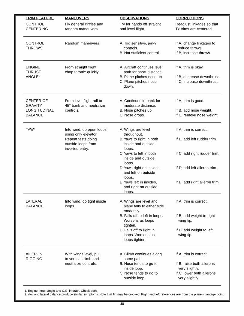
38
TRIM FEATURE MANEUVERS OBSERVATIONS CORRECTIONS
Readjust linkages so thatTx trims are centered.
If A, change linkages toreduce throws.
If B, increase throws.
If A, trim is okay.
If B, decrease downthrust.If C, increase downthrust.
If A, trim is good.
If B, add nose weight.If C, remove nose weight.
If A, trim is correct.
If B, add left rudder trim.
If C, add right rudder trim.
If D, add left aileron trim.
If E, add right aileron trim.
If A, trim is correct.
If B, add weight to rightwing tip.
If C, add weight to leftwing tip.
If A, trim is correct.
If B, raise both aileronsvery slightly.
If C, lower both aileronsvery slightly.
1. Engine thrust angle and C.G. interact. Check both.2. Yaw and lateral balance produce similar symptoms. Note that fin may be crooked. Right and left references are from the plane’s vantage point.
CONTROLCENTERING
CONTROLTHROWS
ENGINETHRUSTANGLE1
CENTER OFGRAVITYLONGITUDINALBALANCE
YAW2
LATERALBALANCE
AILERONRIGGING
Fly general circles andrandom maneuvers.
Random maneuvers
From straight flight,chop throttle quickly.
From level flight roll to45° bank and neutralizecontrols.
Into wind, do open loops,using only elevator.Repeat tests doingoutside loops frominverted entry.
Into wind, do tight insideloops.
With wings level, pullto vertical climb andneutralize controls.
Try for hands off straightand level flight.
A. Too sensitive, jerkycontrols.
B. Not sufficient control.
A. Aircraft continues levelpath for short distance.
B. Plane pitches nose up.C. Plane pitches nose
down.
A. Continues in bank formoderate distance.
B. Nose pitches up.C. Nose drops.
A. Wings are levelthroughout.
B. Yaws to right in bothinside and outsideloops.
C. Yaws to left in bothinside and outsideloops.
D. Yaws right on insides,and left on outsideloops.
E. Yaws left in insides,and right on outsideloops.
A. Wings are level andplane falls to either siderandomly.
B. Falls off to left in loops.Worsens as loops tighten.
C. Falls off to right inloops. Worsens asloops tighten.
A. Climb continues alongsame path.
B. Nose tends to go toinside loop.
C. Nose tends to go tooutside loop.
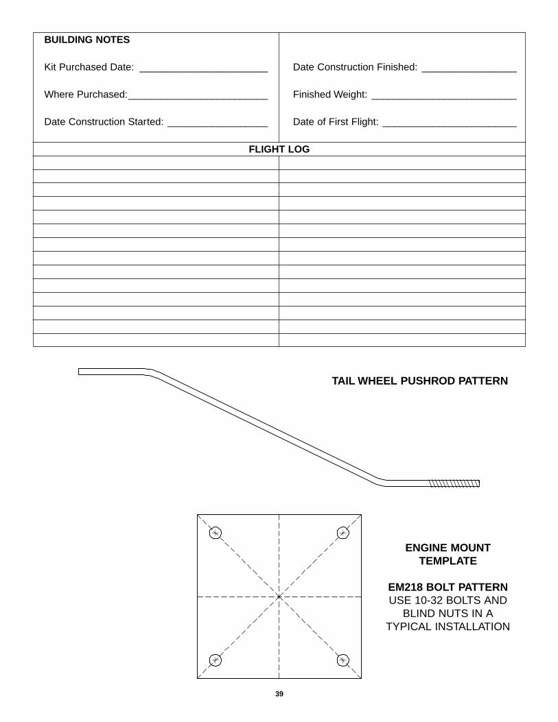
39
BUILDING NOTES
Kit Purchased Date: _______________________
Where Purchased:_________________________
Date Construction Started: __________________
Date Construction Finished: _________________
Finished Weight: __________________________
Date of First Flight: ________________________
FLIGHT LOG
TAIL WHEEL PUSHROD PATTERN
ENGINE MOUNTTEMPLATE
EM218 BOLT PATTERNUSE 10-32 BOLTS AND
BLIND NUTS IN ATYPICAL INSTALLATION


![Extra 300S [40]](https://img.pdfslide.us/doc/110x75/577cd5791a28ab9e789ae1cf/extra-300s-40.jpg)