Embed Size (px)
Citation preview
Instruction Manual
31080 (1/8 DIN)Controller
31080-0-00.p65 3/24/00, 11:58 AM1
INDEX
MOUNTING REQUIREMENTS ........................................ 1CONNECTIONS ............................................................... 1PRELIMINARY HARDWARE SETTINGS ........................ 6INSTRUMENT CONFIGURATION ................................... 8
Configuration procedure .......................................... 8RUN TIME MODE .......................................................... 16
Display function ...................................................... 16Indicators ............................................................... 16Pushbutton functionality duringoperative mode ...................................................... 16Enable/disable the control output .......................... 17Manual function ...................................................... 17Out 1 failure detection function .............................. 18Loop break alarm function ..................................... 18SP/SP2 selection ................................................... 18Direct access to the set point ................................ 19Serial link ................................................................ 19SMART function ..................................................... 19Lamp test ............................................................... 19
RUN TIME PARAMETERS ............................................ 20ERROR MESSAGES ...................................................... 22GENERAL INFORMATIONS .......................................... 24MAINTENANCE .............................................................. 24DEFAULT PARAMETERS ............................................ A.1SECURITY CODES ....................................................... A.2CODING ........................................................................ A.3
31080-0-00.p65 3/24/00, 11:58 AM2
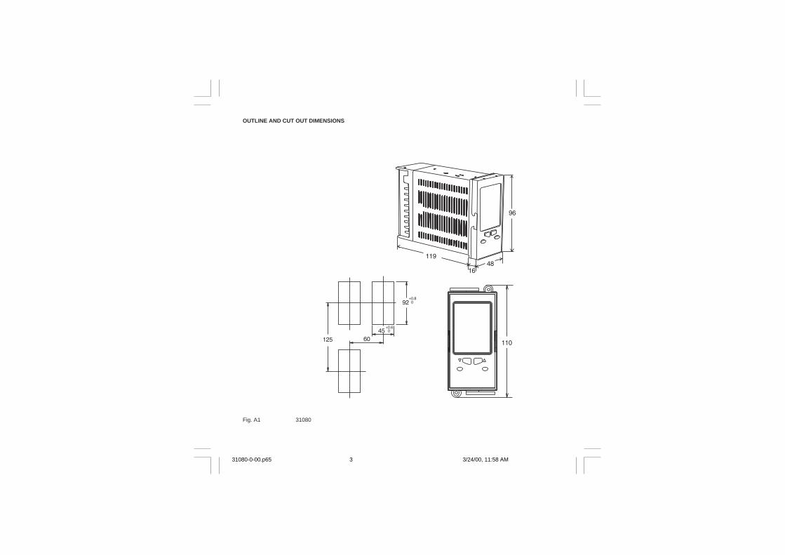
OUTLINE AND CUT OUT DIMENSIONS
Fig. A1 31080
31080-0-00.p65 3/24/00, 11:58 AM3
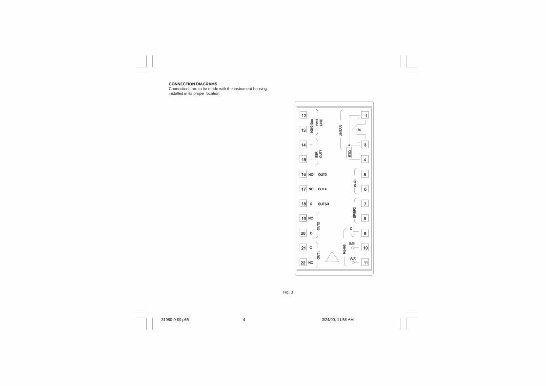
CONNECTION DIAGRAMSConnections are to be made with the instrument housinginstalled in its proper location.
Fig. B
31080-0-00.p65 3/24/00, 11:58 AM4
1
MOUNTING REQUIREMENTS
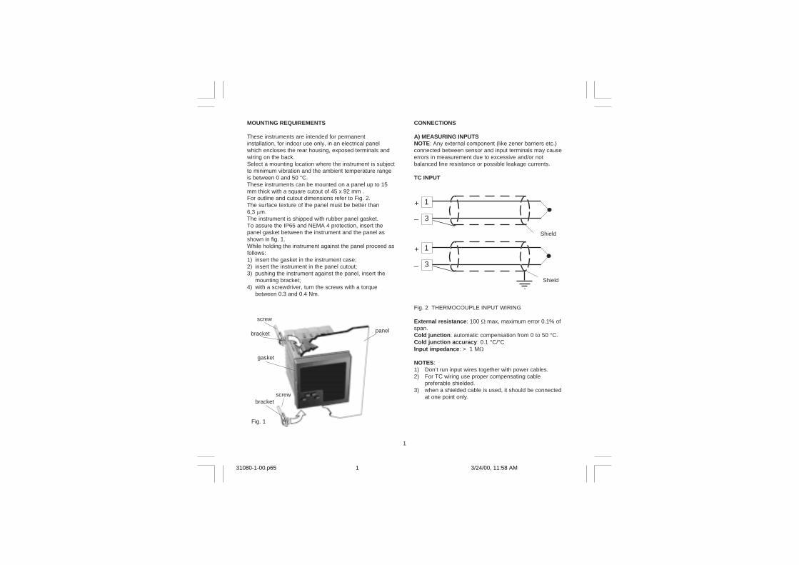
These instruments are intended for permanentinstallation, for indoor use only, in an electrical panelwhich encloses the rear housing, exposed terminals andwiring on the back.Select a mounting location where the instrument is subjectto minimum vibration and the ambient temperature rangeis between 0 and 50 °C.These instruments can be mounted on a panel up to 15mm thick with a square cutout of 45 x 92 mm .For outline and cutout dimensions refer to Fig. 2.The surface texture of the panel must be better than6,3 mm.The instrument is shipped with rubber panel gasket.To assure the IP65 and NEMA 4 protection, insert thepanel gasket between the instrument and the panel asshown in fig. 1.While holding the instrument against the panel proceed asfollows:1) insert the gasket in the instrument case;2) insert the instrument in the panel cutout;3) pushing the instrument against the panel, insert the
mounting bracket;4) with a screwdriver, turn the screws with a torque
between 0.3 and 0.4 Nm.
CONNECTIONS
A) MEASURING INPUTSNOTE: Any external component (like zener barriers etc.)connected between sensor and input terminals may causeerrors in measurement due to excessive and/or notbalanced line resistance or possible leakage currents.
TC INPUT
Fig. 2 THERMOCOUPLE INPUT WIRING
External resistance : 100 W max, maximum error 0.1% ofspan.Cold junction : automatic compensation from 0 to 50 °C.Cold junction accuracy : 0.1 °C/°CInput impedance : > 1 MW
NOTES:1) Don’t run input wires together with power cables.2) For TC wiring use proper compensating cable
preferable shielded.3) when a shielded cable is used, it should be connected
at one point only.
3
+
_
Shield
1
3
+
_
Shield
1
panel
screw
Fig. 1
bracket
gasket
screwbracket
31080-1-00.p65 3/24/00, 11:58 AM1
2
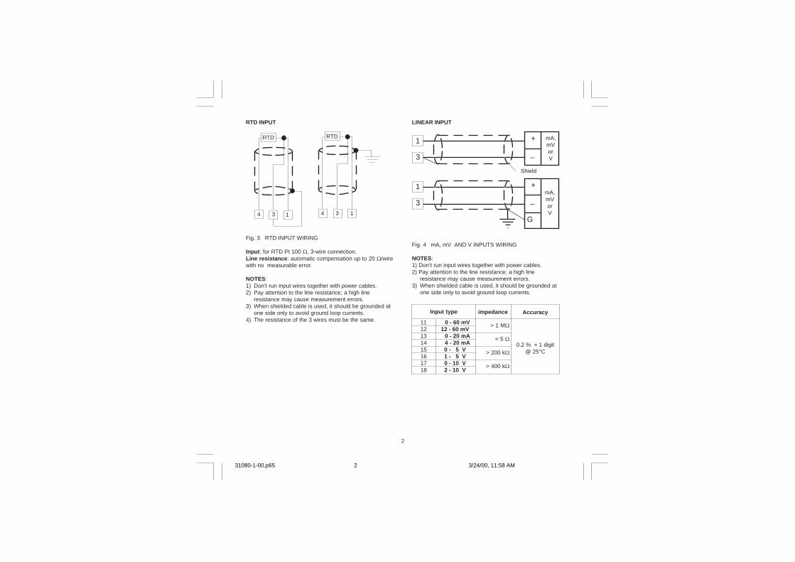
LINEAR INPUT
Fig. 4 mA, mV AND V INPUTS WIRING
NOTES:1) Don’t run input wires together with power cables.2) Pay attention to the line resistance; a high line
resistance may cause measurement errors.3) When shielded cable is used, it should be grounded at
one side only to avoid ground loop currents.
RTD INPUT
Fig. 3 RTD INPUT WIRING
Input : for RTD Pt 100 W, 3-wire connection.Line resistance : automatic compensation up to 20 W/wirewith no measurable error.
NOTES:1) Don’t run input wires together with power cables.2) Pay attention to the line resistance; a high line
resistance may cause measurement errors.3) When shielded cable is used, it should be grounded at
one side only to avoid ground loop currents.4) The resistance of the 3 wires must be the same.
4
RTD
13 4
RTD
13
mA,mVorV3
Shield
1
3
1
G
_
+
_
+mA,mVorV
Input type
1112131415161718
0 - 60 mV12 - 60 mV 0 - 20 mA 4 - 20 mA
0 - 5 V1 - 5 V0 - 10 V2 - 10 V
impedance
> 1 MW
< 5 W
> 200 kW
> 400 kW
Accuracy
0.2 % + 1 digit@ 25°C
31080-1-00.p65 3/24/00, 11:58 AM2
3
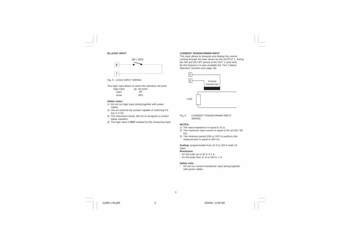
B) LOGIC INPUT
Fig. 5 - LOGIC INPUT WIRING
This logic input allows to select the operative set point.logic input op. set point
open SPclose SP2
Safety notes:1) Do not run logic input wiring together with power
cables.2) Use an external dry contact capable of switching 0.5
mA, 5 V DC.3) The instrument needs 100 ms to recognize a contact
status variation.4) The logic input is NOT isolated by the measuring input
8
SP / SP2
7
CURRENT TRANSFORMER INPUTThis input allows to measure and display the currentrunning through the load, driven by the OUTPUT 1, duringthe ON and the OFF period of the OUT 1 cycle time.By this features it is also available the "Out 1 failuredetection" function (see page 18)
Fig. 6 CURRENT TRANSFORMER INPUTWIRING
NOTES:1) The input impedance is equal to 10 W.2) The maximum input current is equal to 50 mA (50 / 60
Hz).3) The minimum period (ON or OFF) to perform this
measurement is equal to 400 ms.
Scaling : programmable from 10 A to 100 A (with 1Astep).Resolution : - for full scale up to 20 A: 0.1 A. - for full scale from 21 A to 100 A: 1 A
Safety note:- Do not run current transformer input wiring together
with power cables.
Load
Currenttransformer
6
5
31080-1-00.p65 3/24/00, 11:58 AM3
4
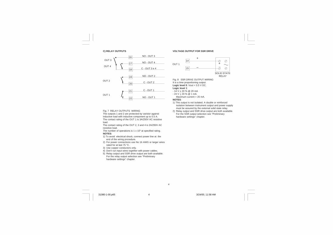
VOLTAGE OUTPUT FOR SSR DRIVE
Fig. 8 SSR DRIVE OUTPUT WIRINGIt is a time proportioning output.Logic level 0 : Vout < 0.5 V DC.Logic level 1 :- 14 V + 20 % @ 20 mA- 24 V + 20 % @ 1 mA.
Maximum current = 20 mA.NOTES:1) This output is not isolated. A double or reinforced
isolation between instrument output and power supplymust be assured by the external solid state relay.
2) Relay output and SSR drive output are both available.For the SSR output selection see "Preliminaryhardware settings" chapter.
C) RELAY OUTPUTS
Fig. 7 RELAY OUTPUTS WIRINGThe outputs 1 and 2 are protected by varistor againstinductive load with inductive component up to 0.5 A.The contact rating of the OUT 1 is 3A/250V AC resistiveload.The contact rating of the OUT 2, 3 and 4 is 2A/250V ACresistive load.The number of operations is 1 x 10⁵ at specified rating.NOTES:1) To avoid electrical shock, connect power line at the
end of the wiring procedure.2) For power connections use No 16 AWG or larger wires
rated for at last 75 °C.3) Use copper conductors only.4) Don’t run input wires together with power cables.5) Relay output and SSR drive output are both available.
For the relay output selection see "Preliminaryhardware settings" chapter.
18
16
17 NO - OUT 4
NO - OUT 3
C - OUT 3 e 4
OUT 3
OUT 4
19
20 C - OUT 2
NO - OUT 2
OUT 2
21
22 NO - OUT 1
C - OUT 1
OUT 1
SOLID STATERELAY
+
_ _+
14
15
OUT 1
31080-1-00.p65 3/24/00, 11:58 AM4
5
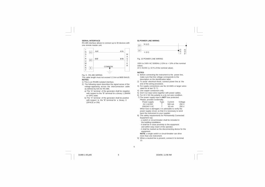
SERIAL INTERFACERS-485 interface allows to connect up to 30 devices withone remote master unit.
Fig. 9 - RS-485 WIRINGThe cable length must not exceed 1.5 km at 9600 BAUD.NOTES:1) This is an RS485 isolated interface.2) The following report describes the signal sense of the
voltage appearing across the interconnection cableas defined by EIA for RS-485.a) The ”A” terminal of the generator shall be negative
with respect to the ”B” terminal for a binary 1 (MARKor OFF) state.
b) The ”A” terminal of the generator shall be positivewith respect to the ”B” terminal for a binary 0(SPACE or ON)
D) POWER LINE WIRING
Fig. 10 POWER LINE WIRING
100V to 240V AC 50/60Hz (-15% to + 10% of the nominalvalue).24 V AC/DC (+ 10 % of the nominal value).
NOTES:1) Before connecting the instrument to the power line,
make sure that line voltage corresponds to thedescription on the identification label.
2) To avoid electrical shock, connect power line at theend of the wiring procedure.
3) For supply connections use No 16 AWG or larger wiresrated for at last 75 °C.
4) Use copper conductors only.5) Don’t run input wires together with power cables.6) For 24 V DC the polarity is a do not care condition. 7) The power supply input is NOT fuse protected.
Please, provide it externally.Power supply Type Current Voltage24 V AC/DC T 500 mA 250 V
100/240 V AC T 63 mA 250 VWhen fuse is damaged, it is advisable to verify thepower supply circuit, so that it is necessary to sendback the instrument to your supplier.
8) The safety requirements for Permanently ConnectedEquipment say:- a switch or circuit-breaker shall be included in
the building installation;- It shall be in close proximity to the equipment
and within easy reach of the operator;- it shall be marked as the disconnecting device for the
equipment.NOTE: a single switch or circuit-breaker can drivemore than one instrument.
9) When a neutral line is present, connect it to terminal13.
12
13N (L2)
L (L1)
N (
L2)
L (L
1)
10
9COMMON
11
B'/BB/B'
A/A' A'/A
MASTER
INSTRUMENT
31080-1-00.p65 3/24/00, 11:58 AM5
6
A
A
B
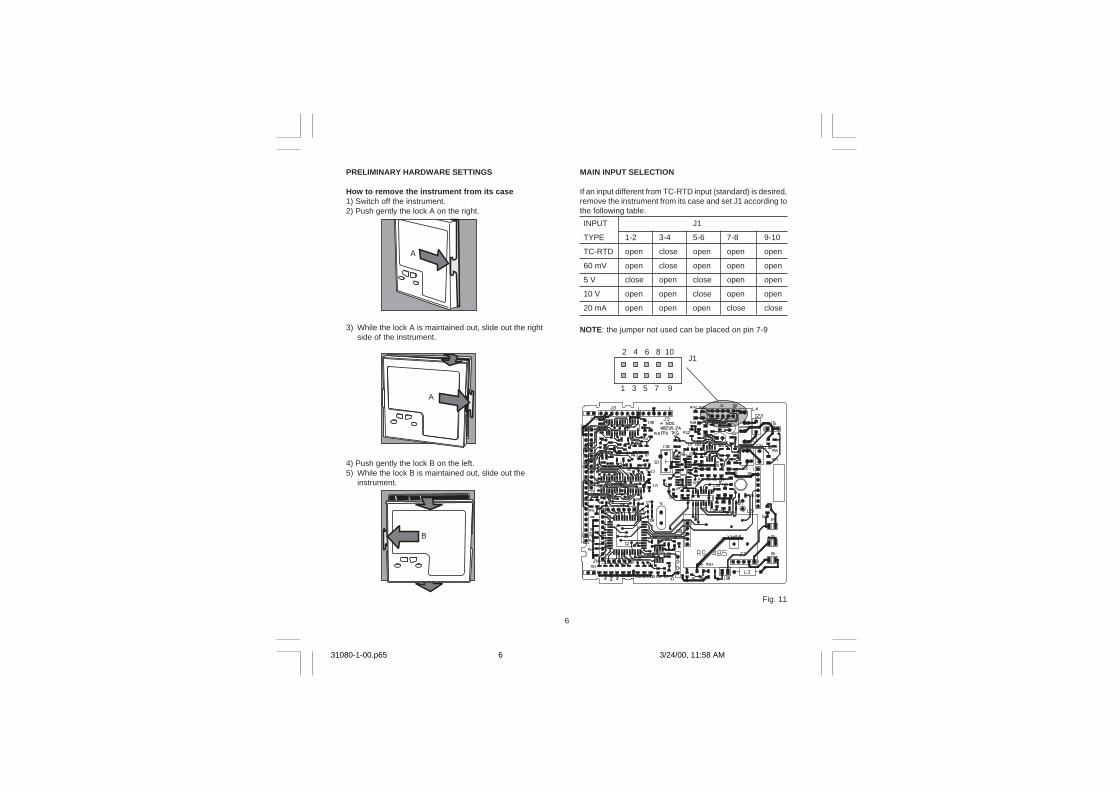
MAIN INPUT SELECTION
If an input different from TC-RTD input (standard) is desired,remove the instrument from its case and set J1 according tothe following table.
INPUT J1
TYPE 1-2 3-4 5-6 7-8 9-10
TC-RTD open close open open open
60 mV open close open open open
5 V close open close open open
10 V open open close open open
20 mA open open open close close
NOTE: the jumper not used can be placed on pin 7-9
PRELIMINARY HARDWARE SETTINGS
How to remove the instrument from its case1) Switch off the instrument.2) Push gently the lock A on the right.
3) While the lock A is maintained out, slide out the rightside of the instrument.
4) Push gently the lock B on the left.5) While the lock B is maintained out, slide out the
instrument.
Fig. 11
1 3 5 7 9
2 4 6 8 10J1
31080-1-00.p65 3/24/00, 11:58 AM6
7
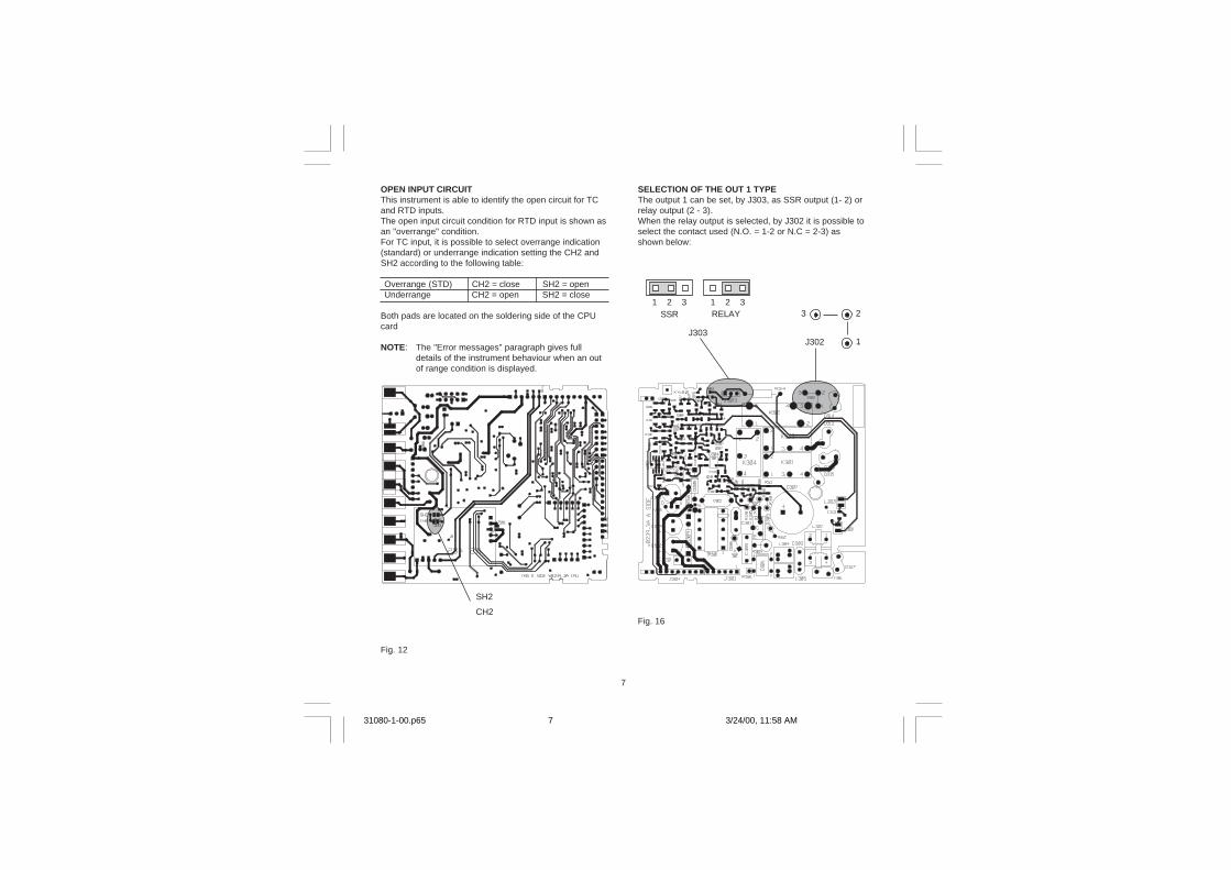
SELECTION OF THE OUT 1 TYPEThe output 1 can be set, by J303, as SSR output (1- 2) orrelay output (2 - 3).When the relay output is selected, by J302 it is possible toselect the contact used (N.O. = 1-2 or N.C = 2-3) asshown below:
Fig. 16
OPEN INPUT CIRCUITThis instrument is able to identify the open circuit for TCand RTD inputs.The open input circuit condition for RTD input is shown asan "overrange" condition.For TC input, it is possible to select overrange indication(standard) or underrange indication setting the CH2 andSH2 according to the following table:
Overrange (STD) CH2 = close SH2 = openUnderrange CH2 = open SH2 = close
Both pads are located on the soldering side of the CPUcard
NOTE: The "Error messages" paragraph gives fulldetails of the instrument behaviour when an outof range condition is displayed.
Fig. 12
SH2
CH2
1 2 3
J303
3 2
1J302
1 2 3SSR RELAY
31080-1-00.p65 3/24/00, 11:58 AM7
8
INSTRUMENT CONFIGURATION
Run time and configuration modesWhen the instrument is in run time mode and nomodification parameter is in progress, the measuredvariable is shown on the upper display, while the set pointis shown on the lower display (we define this condition"normal display mode").
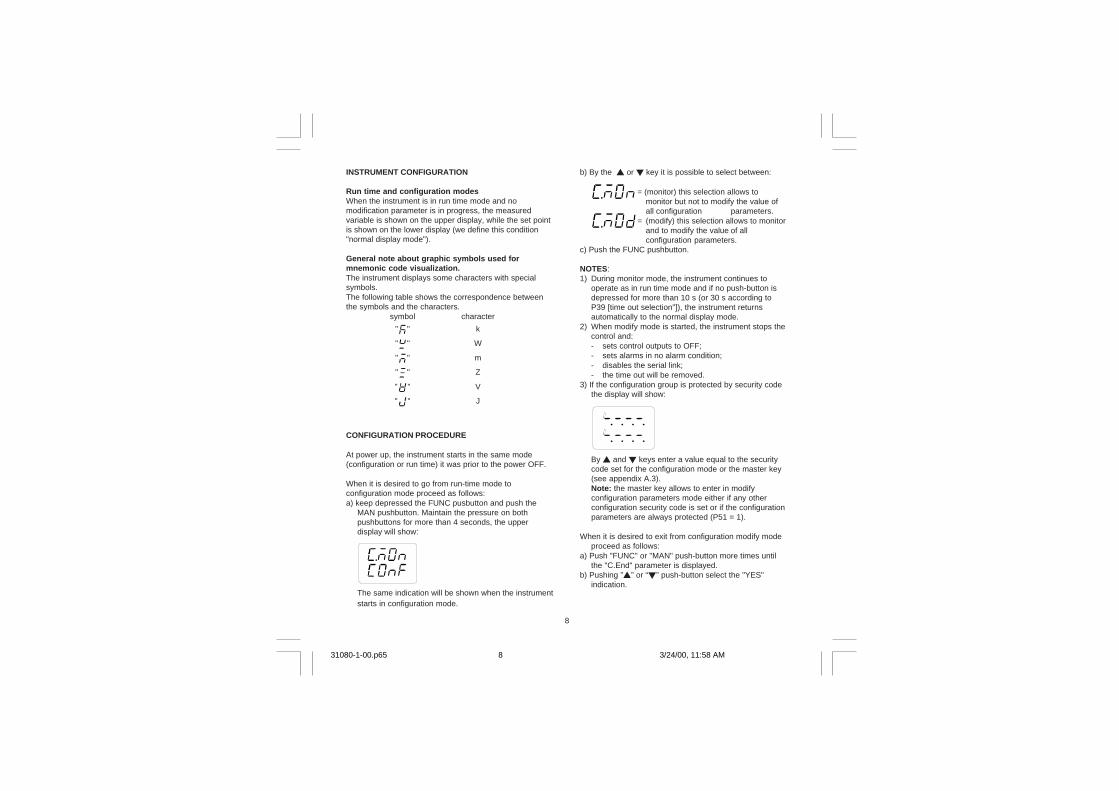
General note about graphic symbols used formnemonic code visualization.The instrument displays some characters with specialsymbols.The following table shows the correspondence betweenthe symbols and the characters.
symbol character
" " k
" " W
" " m
" " Z
" " V
" " J
CONFIGURATION PROCEDURE
At power up, the instrument starts in the same mode(configuration or run time) it was prior to the power OFF.
When it is desired to go from run-time mode toconfiguration mode proceed as follows:a) keep depressed the FUNC pusbutton and push the
MAN pushbutton. Maintain the pressure on bothpushbuttons for more than 4 seconds, the upperdisplay will show:
The same indication will be shown when the instrumentstarts in configuration mode.
b) By the s or t key it is possible to select between:
= (monitor) this selection allows tomonitor but not to modify the value ofall configuration parameters.
= (modify) this selection allows to monitorand to modify the value of allconfiguration parameters.
c) Push the FUNC pushbutton.
NOTES:1) During monitor mode, the instrument continues to
operate as in run time mode and if no push-button isdepressed for more than 10 s (or 30 s according toP39 [time out selection"]), the instrument returnsautomatically to the normal display mode.
2) When modify mode is started, the instrument stops thecontrol and:- sets control outputs to OFF;- sets alarms in no alarm condition;- disables the serial link;- the time out will be removed.
3) If the configuration group is protected by security codethe display will show:
By s and t keys enter a value equal to the securitycode set for the configuration mode or the master key(see appendix A.3).Note: the master key allows to enter in modifyconfiguration parameters mode either if any otherconfiguration security code is set or if the configurationparameters are always protected (P51 = 1).
When it is desired to exit from configuration modify modeproceed as follows:
a) Push "FUNC" or "MAN" push-button more times untilthe "C.End" parameter is displayed.
b) Pushing ”s” or “t” push-button select the "YES"indication.
31080-1-00.p65 3/24/00, 11:58 AM8
9
c) Push “FUNC” push-button. The instrument ends theconfiguration modify mode, preforms an automaticreset and restarts in the run time mode.
Pushbutton function during configuration modeFUNC = This will memorize the new value of the
selected parameter and go to the nextparameter (increasing order).
MAN = This will scroll back the parameters withoutmemorization of the new value.
s = This will increase the value of the selectedparameter
t = This will decrease the value of the selectedparameter.
CONFIGURATION PARAMETERSNotes:1) In the following pages we will describe all the
parameters of the instrument but the instrument willshow only the parameters related with the specifichardware and in accordance with the specificinstrument configuration (i.e. setting OUT 3 equal to 0(not used), all the parameters related with alarm 2 willbe skipped).
2) During configuration mode, the lower display showsthe mnemonic code of the selected parameter whilethe upper display shows the value or the statusassigned to the selected parameter.
dF.Cn = Default configuration parameterloading
Available in modify configuration parameters onlyOFF = No loading datatb1 = Loading European Table default parameters.tb2 = Loading American Table default parameters.NOTE: the list of both default parameter tables is reported
at Appendix A.
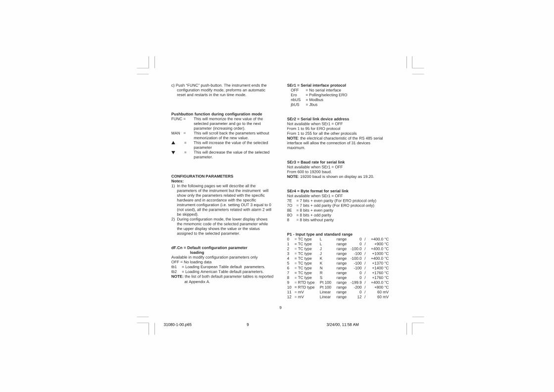
SEr1 = Serial interface protocolOFF = No serial interfaceEro = Polling/selecting EROnbUS = ModbusjbUS = Jbus
SEr2 = Serial link device addressNot available when SEr1 = OFFFrom 1 to 95 for ERO protocolFrom 1 to 255 for all the other protocolsNOTE: the electrical characteristic of the RS 485 serialinterface will allow the connection of 31 devicesmaximum.
SEr3 = Baud rate for serial linkNot available when SEr1 = OFFFrom 600 to 19200 baud.NOTE: 19200 baud is shown on display as 19.20.
SEr4 = Byte format for serial linkNot available when SEr1 = OFF7E = 7 bits + even parity (For ERO protocol only)7O = 7 bits + odd parity (For ERO protocol only)8E = 8 bits + even parity8O = 8 bits + odd parity8 = 8 bits without parity
P1 - Input type and standard range0 = TC type L range 0 / +400.0 °C1 = TC type L range 0 / +900 °C2 = TC type J range -100.0 / +400.0 °C3 = TC type J range -100 / +1000 °C4 = TC type K range -100.0 / +400.0 °C5 = TC type K range -100 / +1370 °C6 = TC type N range -100 / +1400 °C7 = TC type R range 0 / +1760 °C8 = TC type S range 0 / +1760 °C9 = RTD type Pt 100 range -199.9 / +400.0 °C10 = RTD type Pt 100 range -200 / +800 °C11 = mV Linear range 0 / 60 mV12 = mV Linear range 12 / 60 mV
31080-1-00.p65 3/24/00, 11:58 AM9
10
13 = mA Linear range 0 / 20 mA14 = mA Linear range 4 / 20 mA15 = V Linear range 0 / 5 V16 = V Linear range 1 / 5 V17 = V Linear range 0 / 10 V18 = V Linear range 2 / 10 V19 = TC type L range 0 / +1650 °F20 = TC type J range -150 / +1830 °F21 = TC type K range -150 / +2500 °F22 = TC type N range -150 / +2550 °F23 = TC type R range 0 / +3200 °F24 = TC type S range 0 / +3200 °F25 = RTD type Pt 100 range -199.9 / +400.0 °F26 = RTD type Pt 100 range -330 / +1470 °F27 = TC type T range -199.9 / 400.0 °C28 = TC type T range -330 / 750 °FNOTE: selecting P1 = 0, 2, 4, 9, 25 or 27, the instrumentset automatically P40 = FLtr. For all the remaining rangesit will set P40 = nOFL.
P2 = Decimal point positionThis parameter is available only when a linear input isselected (P1 = 11 to 18).
----. = No decimal figure.---.- = One decimal figure.--.-- = Two decimal figures.-.--- = Three decimal figures.
P3 = Initial scale valueFor linear inputs it is programmable from -1999 to 4000.For TC and RTD input it is programmable within the inputrange.Notes:1) When this parameter is modified, rL parameter will be
re-aligned to it.2) If a linear input is selected, the value of this parameter
can be greater than P4 in order to get a reversereadout.
P4 = Full scale valueFor linear inputs it is programmable from -1999 to 4000.For TC and RTD inputs, it is programmable within theinput range.
Notes:1) When this parameter is modified, rH parameter will be
re-aligned to it.2) If a linear input is selected, the value of this parameter
can be smaller than P3 in order to get a reversereadout.
The initial and full scale values determine the input spanwhich is used by the PID algorithm, the SMART and thealarm functions.
NOTE: the minimum input span (S = P4 - P3), in absolutevalue, should be set as follows:- For linear inputs, S > 100 units.- For TC input with °C readout, S > 300 °C.- For TC input with °F readout, S > 550 °F.- For RTD input with °C readout, S > 100 °C.- For RTD input with °F readout, S > 200 °F.
P5 = Output 1 typeChanging the P5 setting, also Cy1 parameter will beautomatically modified.rEL = Relay [the cycle time (Cy1) will be forced to 15 s]SSr = SSR [the cycle time (Cy1) will be forced to 4 s]
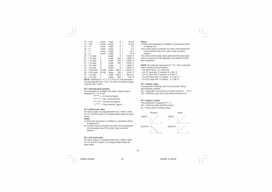
P6 = Output 1 actionThis parameter is skipped if P7 = 4rEV = Reverse action (Heating action)dir = Direct action (Cooling action)
t
INPUT
t
OUTPUT
t
INPUT
t
OUTPUT
Reverse Direct
31080-1-00.p65 3/24/00, 11:58 AM10
11
P7 = Output 2 function.0 = output not used.1 = it is used as Alarm 1 output and the alarm 1 is
programmed as process alarm.2 = it is used as Alarm 1 output and the alarm 1 is
programmed as band alarm.3 = it is used as Alarm 1 output and the alarm 1 is
programmed as deviation alarm.4 = it is used as secondary control output (Cooling
output).NOTE: setting P7 = 4, the P6 parameter is forced to "rEV".
P8 = Cooling media.Available only when P7 = 4- AIr = Air is used as cooling media.- OIL = Oil is used as cooling media.- H2O = Direct water is used as cooling media.Changing P8 parameter, the instrument forces the cycletime and relative cooling gain parameter to the defaultvalue related with the chosen cooling mediaWhen P8 = AIr - Cy2 = 10 s and rC = 1.00
P8 = OIL - Cy2 = 4 s and rC = 0.80P8 = H2O - Cy2 = 2 and rC = 0.40
P9 = Alarm 1 operating modeAvailable only when P7 is equal to 1,2 or 3.H.A. = High alarm (outside for band alarm) with
automatic reset.L.A. = Low alarm (inside for band alarm) with automatic
reset.H.L. = High alarm (outside for band alarm) with manual
reset (latched alarm).L.L. = low alarm (inside for band alarm) with manual
reset (latched alarm).
P10 = Current measurement (in Amp.)(See also "Display function" and "Out 1 failure detection").OFF = Current measurement disabledn.O. = Set P10 to n.O. when the load is energized during
the ON status of the instrument output (relay ener-gized or SSR output status 1).
n.C. = Set P10 to n.C. when the load is energized duringthe OFF status of the instrument output (relay de-energized or SSR output status 0).
P11 = Current transformer rangeThis parameter is present only if P10 is different from OFF.Programmable from 10 to 100 A.
P12 = Output 3 function0 = Output not used for alarm 2.1 = it is used as Alarm 2 output and the alarm 2 is
programmed as process alarm.2 = it is used as Alarm 2 output and the alarm 2 is
programmed as band alarm.3 = it is used as Alarm 2 output and the alarm 2 is
programmed as deviation alarm.NOTE: The output 3 relay operates as a logic OR amongthe alarm 2, the "Out 1 failure detection" (OFD) functionand the "Loop break alarm" (LBA) function.
P13 = Alarm 2 operating mode & type of resetassigned to "Output 1 failure detection" and"Loop Break Alarm" functions.
Available only when P12 is different from 0 or P10 isdifferent from OFF or P47 is different from dIS.H.A. = High alarm (outside for band alarm) with
automatic reset.L.A. = Low alarm (inside for band alarm) with automatic
reset.H.L. = High alarm (outside band) with manual reset
(latched alarm).L.L. = low alarm (inside band) with manual reset
(latched alarm).NOTE: The "Out 1 failure detection" and "loop breakalarm" functions assume only the selected reset type(manual or automatic).
P14 = Output 4 function0 = Output not used.1 = it is used as Alarm 3 output and the alarm 3 is
programmed as process alarm.2 = it is used as Alarm 3 output and the alarm 3 is
programmed as band alarm.3 = it is used as Alarm 3 output and the alarm 3 is
programmed as deviation alarm.
31080-1-00.p65 3/24/00, 11:58 AM11
12
P15 = Alarm 3 operative modeAvailable only when P14 is different from 0.H.A. = High alarm (outside for band alarm) with
automatic reset.L.A. = Low alarm (inside for band alarm) with automatic
reset.H.L. = High alarm (outside band) with manual reset
(latched alarm).L.L. = low alarm (inside band) with manual reset
(latched alarm).
P16 = Programmability of the alarm 3.Available only when P14 is different from 0.OPrt = Alarm 3 threshold and hysteresis are
programmable in operating mode.COnF = Alarm 3 threshold and hysteresis are
programmable in configuration mode.
P17 = Alarm 3 threshold valueAvailable only when P14 is different from 0 and P16 isequal to "COnF".Range:- For process alarm - within the span limits (P4 - P3)- For band alarm - from 0 to 500 units.- For deviation alarm - from -500 to 500 units.
P18 = Alarm 3 hysteresis valueAvailable only when P14 is different from 0 and P16 isequal to "COnF".Range: from 0.1% to 10.0 % of the span (P4 - P3)
P19= Soft Start thresholdThreshold value, in eng. units, to initiate the "Soft start"function (output power limiting) at start up.Range: within the readout span.NOTE: this threshold value will not be taken into accountwhen tOL = InF.
P20 = Safety lock0 = No parameter protection. The device is always in
unlock condition and all parameters can be modified.
1 = The device is always in lock condition and no one ofthe parameters (exception made for set points [SP,SP2] and alarm manual reset) can be modified (forSMART status see P31 parameter).
From 2 to 4999 = This combination number is a secretvalue to be used, in run time (see nnn parameter) toput device in lock/unlock condition.For SP, SP2 and manual reset of the alarms, thelock/unlock condition has no effect (for SMARTstatus see P31).
From 5000 to 9999 = This combination number is a secretvalue to be used, in run time (see nnn parameter) toput device in lock/unlock condition.For SP, SP2, manual reset of the alarm, AL1, AL2,AL3, Hbd and SCA, the lock/unlock condition has noeffect (for SMART status see P31).
NOTE: when safety lock is selected, the secret value cannot be displayed anymore and the display will show 0, 1,SFt.A (when P20 is encompassed between 2 and 4999)or SFt.b (when P20 is encompassed between 5000 and9999)
P21 = Alarm 1 actionAvailable only when P7 is different from 0 or 4.dir = direct action (relay energized in alarm condition)rEV = reverse action (relay de-energized in alarm
condition)
P22 = Alarm 1 stand-by function (mask)Available only when P7 is different from 0 or 4.OFF = stand-by function (mask alarm) disabledOn = stand-by function (mask alarm) enabledNOTE: If the alarm is programmed as band or deviationalarm, this function masks the alarm condition after a setpoint change or at the instrument start-up until processvariable reaches the alarm threshold plus or minushysteresis. If the alarm is programmed as a processalarm, this function masks the alarm condition atinstrument start-up until the process variable reaches thealarm threshold plus or minus hysteresis.
31080-1-00.p65 3/24/00, 11:58 AM12
13
P23 = action of: the Alarm 2, the "Out 1 failuredetection" function and of the "Loop breakalarm" function.
Available only when P12 is different from 0 or P10 isdifferent from "OFF" or P47 is different from dIS.dir = direct (relay energized in alarm condition)rEV = reverse (relay de-energized in alarm condition)
P24 = Alarm 2 stand-by function (mask alarm)Available only when P12 is different from 0.OFF = stand-by function (mask alarm) disabledOn = stand-by function (mask alarm) enabledNOTE: see NOTE about P22 parameter.P25 = Alarm 3 actionAvailable only when P14 is different from 0.dir = direct (relay energized in alarm condition)rEV = reverse (relay de-energized in alarm condition)
P26 = Alarm 3 stand-by function (mask alarm)Available only when P14 is different from 0.OFF = stand-by function (mask alarm) disabledOn = stand-by function (mask alarm) enabledNOTE: see NOTE about P22 parameter.
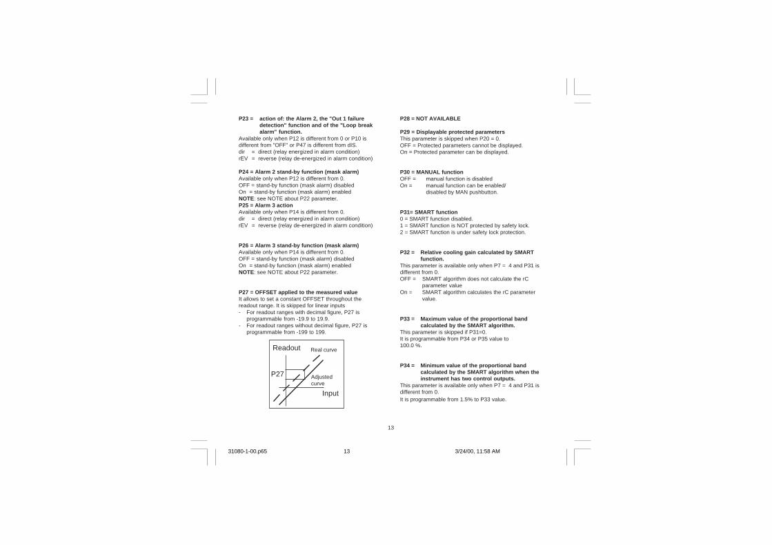
P27 = OFFSET applied to the measured valueIt allows to set a constant OFFSET throughout thereadout range. It is skipped for linear inputs- For readout ranges with decimal figure, P27 is
programmable from -19.9 to 19.9.- For readout ranges without decimal figure, P27 is
programmable from -199 to 199.
P28 = NOT AVAILABLE
P29 = Displayable protected parametersThis parameter is skipped when P20 = 0.OFF = Protected parameters cannot be displayed.On = Protected parameter can be displayed.
P30 = MANUAL functionOFF = manual function is disabledOn = manual function can be enabled/
disabled by MAN pushbutton.
P31= SMART function0 = SMART function disabled.1 = SMART function is NOT protected by safety lock.2 = SMART function is under safety lock protection.
P32 = Relative cooling gain calculated by SMARTfunction.
This parameter is available only when P7 = 4 and P31 isdifferent from 0.OFF = SMART algorithm does not calculate the rC
parameter valueOn = SMART algorithm calculates the rC parameter
value.
P33 = Maximum value of the proportional bandcalculated by the SMART algorithm.
This parameter is skipped if P31=0.It is programmable from P34 or P35 value to100.0 %.
P34 = Minimum value of the proportional bandcalculated by the SMART algorithm when theinstrument has two control outputs.
This parameter is available only when P7 = 4 and P31 isdifferent from 0.It is programmable from 1.5% to P33 value.
Real curveReadout
Adjustedcurve
Input
P27
31080-1-00.p65 3/24/00, 11:58 AM13
14
P35 = Minimum value of the proportional bandcalculated by the SMART algorithm when theinstrument has one control output.
This parameter is skipped if P7 = 4 or P31=0.It is programmable from 1.0 % to P33 value.
P36 = Minimum value of the integral time calculatedby the SMART algorithm.
This parameter is skipped if P31=0.It is programmable from 1 second (00.01) to 2 minutes
P37 = Device status at instrument start up.This parameter is skipped when P30 = OFF.0 = the instrument starts in AUTO mode.1 = It starts in the same way it was prior to the power shut
down. If the instrument was in manual mode, the poweroutput will be set to 0.
P38 = NOT AVAILABLE
P39 = Timeout selectionThis parameter allows to set the time duration of thetimeout for parameter setting used by the instrumentduring the operating mode.tn. 10 = 10 secondstn 30 = 30 seconds
P40 = Digital filter on the displayed valueIt is possible to apply to the displayed value a digital filterof the first order with a time constant equal to:
- 4 s for TC and RTD inputs- 2 s for linear inputs
noFL. = no filterFLtr = filter enabled
P41 = Conditions for output safety value0 = No safety value (see "Error Messages")1 = Safety value applied when overrange or underrange
condition is detected.
2 = Safety value applied when overrange condition isdetected.
3 = Safety value applied when underrange condition isdetected.
P42 = Output safety valueThis parameter is skipped when P41 = 0This value can be set- from 0 to 100 % when P7 is different from 4- from -100 % to 100 % when P7 is equal to 4
P43 = Extension of the anti-reset-wind upRange: from -30 to +30 % of the proportional band.NOTE: a positive value increases the high limit of the anti-reset-wind up (over set point) while a negative valuedecreases the low limit of the anti-reset-wind up (underset point).
P44 = Control action typePid - the instrument operates with a PID algorithm.Pi - the instrument operates with a PI algorithm.
P45 = Set point indicationFn.SP = during operative mode, when the instrument
performs a ramp, it will show the final set pointvalue.
OP.SP = during operative mode, when the instrumentperforms a ramp, it will show the operative setpoint.
P46= Operative set point alignment at instrument startup.
0 = At start up, the operative set point will be aligned toSP or SP2 according to the status of the logic input.
1 = At start up, the operative set point will be aligned tothe measured value an then it will reach the selectedset point with a programmable ramp (see Grd1 andGrd2 operative parameters).
NOTE: if the instrument detects an out of range or anerror condition on the measured value it will operate asdescribed for P46 = 0.
31080-1-00.p65 3/24/00, 11:58 AM14
15
P47 = "Loop break alarm" function.dIS = Alarm not usedEnb = The alarm condition of the "Loop break alarm"
(LBA) will be shown by the OUT 3 LED only.EnbO = The alarm condition of the "Loop break alarm"
(LBA) will be shown by the OUT 3 LED and bythe OUT 3 relay status.
NOTES:1) The alarm 2, the Output 1 failure detection and the loop
break alarm are in OR condition on the same output(OUT 3).
2) The loop break alarm reset type is programmed by P13parameter.
3) For more details see "Loop Break Alarm function" atpag 18.
P48 = "Loop break alarm" deviation.This parameter is available only when P47 is differentfrom dIS.Programmable from 0 to 500 units
P49 = "Loop break alarm" time.This parameter is available only when P47 is differentfrom dIS.Programmable from 00.01 to 40.00 mm.ss.
P50 = "Loop break alarm" hysteresis.This parameter is available only when P47 is differentfrom dIS.Programmable from 1to 50% of the power output.
P51 = Security code for configuration parameters0 No protection (it is always possible to modify all
configuration parameters);1 always protected (it is not possible to modify any
configuration parameter);from 2 to 9999 security code for configuration parameter
protection.Notes:1) If a value from 2 to 9999 has been assigned as security
code it cannot be displayed anymore, when returningon this parameter the display will show "On".
2) If the security code is forgotten a new value can be set.3) For configuration parameter only is available a passe-
partout code, by this code it is possible to enter inmodify configuration mode even if the configurationparameters are protected (S.CnF = 1 or from 2 to9999).The passe-partout code is located in Appendix A.
4) Fill out and cut the part of the Appendix A reserved tothe security codes if it is desired to keep them secrets.
C. End = End configurationThis parameter allows to come back to the run time mode.NO = the instrument remains in configuration mode and
comes back to the first display of the configura-tion mode (dF.Cn).
YES = This selection ends the configuration mode. theinstrument performs an automatic reset andrestart the run time mode.
31080-1-00.p65 3/24/00, 11:58 AM15
16
RUN TIME MODE
DISPLAY FUNCTIONSThe upper display shows the measured value while thelower display shows the programmed set point value (wedefine the above condition as “normal display mode”).Note : When the rate of change (Grd1, Grd2) is utilized,
the displayed set point value may be differentfrom the operating set point.
It is possible to change the information on the lowerdisplay as follows:- Push the FUNC pushbutton for more than 3 s but less
than 10 s. The lower display will show "A." followed bythe current consumed by the load (driven by the OUT1) when the load is in ON condition (see also "OUT 1failure detection").
- Push "FUNC" pushbutton again. The lower display willshow "b." followed by the leakage current running inthe load (driven by the OUT 1) when the load is in OFFcondition (see also "OUT 1 failure detection").
- Push "FUNC" pushbutton again. The lower display willshow "H." followed by OUT 1 power value (from 0 to100%).
- Push FUNC pushbutton again. The lower display willshow "C." followed by OUT 2 power value (from 0 to100%).
- Push FUNC pushbutton again. The display will returnin "Normal Display Mode".
NOTE: The "A.", "b" and "C." informations will bedisplayed only if the relative function has been previouslyconfigured.
When no pushbutton is pressed during the time out (seeP39), the display will automatically return in "NormalDisplay Mode".In order to keep continuously the desired information onthe lower display, depress "s" or "t" push- buttons toremove the timeout.When is desired to return in "Normal Display Mode" pushFUNC push-button again.
INDICATORS°C Lit when the process variable is shown in Celsius
degree.°F Lit when the process variable is shown in
Fahrenheit degree.SMRT Flashing when the first part of the SMART
algorithm is active.Lit when the second part of the SMART algorithmis active.
OUT 1 Lit when the OUT 1 is in ON condition.OUT 2 Lit when OUT 2 is ON or alarm 1 is in the alarm
state.OUT3 Lit when the alarm 2 is in the alarm state.
Flashing with slow rate when the "Out 1 failuredetection" or/and "Loop break alarm" are in alarmstate.Flashing with high rate when the "Out 1 failuredetection" or "Loop break alarm" is in the alarmstate and alarm 2 is in alarm state.
OUT4 Lit when the alarm 3 is in alarm condition.REM Lit when the instrument is in REMOTE condition
(functions and parameters are controlled viaserial link).
SPX Lit when SP2 is used.Flashes when a set point from serial link is used.
MAN Lit when the instrument is in MANUAL mode.
Pushbutton functionality during operating mode.FUNC = o when the instrument is in "normal display
mode"1) with a brief pressure (<3 s) it starts the
parameter modification procedure.2) with a pressure more than 3 s but less
than 10s, it changes the indication on thelower display (see "display function").
3) with a pressure more than 10 s, itenables the "Lamp test" (see "Lamptest")
o During parameter modification, it allows tomemorize the new value of the selectedparameter and go to the next parameter(increasing order).
31080-1-00.p65 3/24/00, 11:58 AM16
17
ENABLE/DISABLE THE CONTROL OUTPUTWhen the instrument is in "normal display mode", bykeeping depressed for more than 5 s the s and FUNCpushbuttons, it is possible to disable the control outputs.In this open loop mode the device will function as anindicator, the lower display will show the word OFF and allcontrol outputs will be in the OFF state.When the control outputs are disabled the alarms are alsoin non alarm condition.The alarms output conditions depend on the alarm actiontype (see P21-P23-P25).Depress for more than 5 s the s and FUNC pushbuttonsto restore the control status.The alarm stand-by function, if configured, will beactivated as per power up.If a shut down occurs when the control output is disabled,at instrument power up the control output will be disabledagain.
MANUAL FUNCTIONIt is possible to enter in MANUAL mode (only if enabled byP30=On) by depressing the MAN pushbutton for morethan 1 sec.The command is accepted and executed only if thedisplay is in "Normal Display Mode".When in MANUAL mode the LED MAN lights up while thelower display shows the power output values.The value of OUT 1 is shown by the two most significantdigits while the value of OUT 2 (if present) is shown by thetwo less significant digits.The decimal point between the two values will be flashingto indicate instrument in MANUAL mode.Note :
- The graphic symbol " " is used for OUT1 = 100 %- The graphic symbol " " is used for OUT2 = 100 %
The power output can be modified by using s and tpushbuttons.By depressing, for more than 2 seconds, MAN pushbuttonagain the device returns in AUTO mode.
MAN = o when the instrument is in "normal displaymode", pushing MAN pushbutton for morethan 1 s, it is possible to enable or disablethe manual function.
o During parameter modification, it allows toscroll back the parameters withoutmemorizing the new setting.
s = o During parameter modification, it allows toincrease the value of the selectedparameter
o During MANUAL mode, it allows to increasethe output value.
t = o During parameter modification, it allows todecrease the value of the selectedparameter
o During MANUAL mode, it allows todecrease the output value.
s+MAN = During parameter modification they allow tojump to the maximum programmable value.
t+MAN = During parameter modification they allow tojump to the minimum programmable value.
s + FUNC = During parameter modification they allow toincrease the value under modification withhigher rate.
t + FUNC = During parameter modification they allow todecrease the value under modification withhigher rate.
FUNC + MAN =When the instrument is in normal displaymode, pushing the two buttons for morethan 4 seconds, the instrument will go inconfiguration mode.
s + t = They allow to load the run time defaultparameters.
NOTE: a 10 or 30 seconds time out (see P 39) can beselected for parameter modification during run time mode.If, during operative parameter modification, no pushbuttonis pressed for more than 10 (30) seconds, the instrumentgoes automatically to the “normal display mode” and theeventual modification of the last parameter will be lost.
31080-1-00.p65 3/24/00, 11:58 AM17

18
The transfer from AUTO to MANUAL and viceversa isbumpless (this function is not provided if integral action isexcluded).If transfer from AUTO to MANUAL is performed during thefirst part of SMART algorithm (TUNE) when returning inAUTO the device will be forced automatically to thesecond part of the SMART algorithm (ADAPTIVE).At power up the device will be in the AUTO mode or as itwas left prior to power shut down depending on P37configuration selection.Note : When start up occurs in Manual mode the power
output (OUT1 - OUT2) is set to 0.
OUT 1 FAILURE DETECTION FUNCTIONThe device is capable (for the load driven by the OUT 1)to measure and display:- the current running in the load when the load is
energized- the leakage current, flowing through the load, when the
load is de-energized.If the P10 parameter has been correctly set, theinstrument generates an alarm when:- the current running in the load is lower than the "Hbd"
parameter value (It shows a partial or total break downof the load, the break down of the actuator or a powerdown due to a protection or a fuse intervention);
- the leakage current is higher than the "SCA" parametervalue (It shows a short circuit of the actuator).
The "Display function" paragraph describes how to showthe two current values.A fault condition is shown by OUT 3 LED flashing and byOUT 3 relay status.If the ON or OFF period is lower than 400 ms the relativemeasurement couldn't be performed and the instrumentwill show flashing the last measured value.
"LOOP BREAK ALARM" FUNCTIONThe functioning principle of this alarm is based on theconcept that, with a steady load and steady power output,the process rate of rise [deviation (P48)/time (P49)] issteady as well.Thus, analyzing the process rate of rise of the limitconditions it is possible to estimate the two rates of risewhich define the correct process behaviour.The limit conditions are:3 for one control output: 0% and the value of the "OLH"
parameter or3 for two control outputs: 100% and the value of the
"OLH" parameter.The LBA function is automatically activated when thecontrol algorithm requires the maximum or the minimumpower and, if the process response is slower than theestimated rate of rise, the instrument generates an alarmindication in order to show that one or more element ofthe control loop is in fault condition.Deviation: from 0 to 500 units.Timer: from 1 sec. to 40 min.Hysteresis : from 1% to 50 % of the output span.NOTES:1) The LBA does not operate during the soft start.2) If the instrument operates with the SMART function, the
LBA may be operating.3) For this special function the hysteresis is related with
the power output value and not with its rate of rise.
SP/SP2 SELECTIONIt is possible to select the operating set point (SP or SP2) onlyby a logic input (terminals 7 and 8).By setting P45, it is possible to display the final or theoperative set point during a ramp execution.
31080-1-00.p65 3/24/00, 11:58 AM18
19
DIRECT ACCESS TO SET POINTWhen the device is in AUTO mode and in “Normal DisplayMode”, it is possible to access directly to set pointmodification (SP or SP2).Pushing s or t for more than 2 s, the set point will beginchanging.The new setpoint value becomes operative since nopushbutton has been depressed at the end of 2 stimeout.
SERIAL LINKThe device can be connected to a host computer by aserial link.The host can put the device in LOCAL (functions andparameters are controlled via keyboard) or in REMOTE(functions and parameters are controlled via serial link)mode.The REMOTE status is signalled by a LED labelled REM.This instrument allows to modify the run time andconfiguration parameters via serial link.The necessary conditions to implement this function arethe following:1) Serial parameters from SEr1 to SEr4 should be
properly configured.2) Device must be in the RUN TIME mode
During the downloading of configuration the devicegoes in open loop with all output in OFF state.
At the end of configuration procedure, the device performsan automatic reset and then returns to close loop control.
SMART functionIt is used to optimize automatically the control action.At instrument power up, if the SMART is ON, the secondalgorithm will be enabled.To enable the SMART function, push the FUNCpushbutton until "Sñrt" parameter is shown.Pushing s or t set the display "On" and push theFUNC pushbutton.The SMRT LED will turn on or flashing according to theselected algorithm.When the smart function is enabled, it is possible todisplay but not to modify the control parameters (Pb, ti, td,and rC).To disable the SMART function, push the FUNCpushbutton again until "Sñrt" parameter is shown.Pushing s or t set the display "OFF" and push theFUNC pushbutton. The SMRT LED will turn OFF.The instrument will maintain the current set of controlparameter and will enabled parameter modification.NOTES:1) When ON/OFF control is programmed (Pb=0), the
SMART function is disabled.2) The SMART enabling/disabling can be protected by
safety key (see P31).
LAMP TESTWhen it is desired to verify the display efficiency, pushFUNC pushbutton for more than 10 s. The instrument willturn ON, with a 50 % duty cycle, all the LEDs of thedisplay (we define this function "LAMP TEST").No time out is applied to the LAMP TEST.When it is desired to come back to the normal displaymode, push FUNC pushbutton again.During the lamp test the instrument continues to controlthe process but no keyboard function is available(exception made for FUNC pushbutton).
31080-1-00.p65 3/24/00, 11:58 AM19
20
RUN TIME PARAMETERSPush the FUNC pushbutton, the lower display will showthe code while the upper display will show the value or thestatus (On or OFF) of the selected parameter.By s or t pushbutton it is possible to set the desiredvalue or the desired status.Pushing the FUNC pushbutton, the instrument memorizesthe new value (or the new status) and goes to the nextparameter.Some of the following parameter may be skippedaccording to the instrument configuration.
Param. DESCRIPTION
SP Set point (in eng. units).Range: from rL to rH.SP is operative when the logic input is open.
Sñrt SMART status .The On or OFF indication shows the currentstatus of the SMART function (enabled ordisabled respectively).Set On to enable the SMART function.Set OFF to disable the SMART function.
n.rSt Manual reset of the alarms .This parameter is skipped if none of the alarmshave the manual reset function.Set On and push FUNC to reset the alarms.
SP2 Set point 2 (in eng. units).Range: from rL to rH.SP2 is operative when the logic input is closed.
nnn Software key for parameter protection .This parameter is skipped if P20 = 0 or 1On = the instrument is in LOCK conditionOFF = the instrument is in UNLOCK conditionWhen it is desired to switch from LOCK toUNLOCK condition, set a value equal to P20parameter.When it is desired to switch from UNLOCK toLOCK condition, set a value different from P20parameter.
AL1 Alarm 1 thresholdThis parameter is available only if P 7 is equalto 1, 2 or 3.
Ranges:- Span limits for process alarm.- From 0 to 500 units for band alarm.- From -500 to 500 units for deviationalarm.
HSA1 Alarm 1 hysteresisThis parameter is available only if P 7 is equalto 1, 2 or 3.Range: From 0.1% to 10.0% of the input spanor 1 LSD.Note : If the hysteresis of a band alarm is largerthan the alarm band, the instrument will use anhysteresis value equal to the programmed bandminus 1 digit.
AL2 Alarm 2 thresholdThis parameter is available only if P 12 is equalto 1, 2 or 3.For other details see AL1 parameter.
HSA2 Alarm 2 hysteresisThis parameter is available only if P 12 is equalto 1, 2 or 3.For other details see HSA1 parameter.
AL3 Alarm 3 thresholdThis parameter is available only if P 14 is equalto 1, 2 or 3 and P16 = OPrt.For range details see AL1 parameter.
HSA3 Alarm 3 hysteresisThis parameter is available only if P 14 is equalto 1, 2 or 3 and P16 = OPrt.For other details see HSA1 parameter.
Pb Proportional bandRange:- From 1.0% to 100.0% of the input spanwhen P 7 is different from 4.- From 1.5% to 100.0% of the input spanwhen P 7 is equal to 4.When Pb parameter is set to 0, the controlaction becomes ON/OFF.Note : When device is working with SMARTalgorithm the Pb value will be limited by P33and P35 parameters (when P7 is different from4) or P33 and P34 parameters (when P7 isequal to 4)
31080-1-00.p65 3/24/00, 11:58 AM20
21
HyS Hysteresis for ON/OFF control actionAvailable only when Pb=0.Range: from 0.1% to 10.0% of the input span.
ti Integral timeThis parameter is skipped if Pb=0 (ON/OFFaction).Range: from 00.01 to 20.00 [mm.ss]. Abovethis value the display blanks and integral actionis excludedNote : When the device is working with SMARTalgorithm, the minimum value of the integraltime will be limited by P36 parameter.
td Derivative timeThis parameter is skipped if Pb=0 (ON/OFFaction) or P44 = Pi.Range: From 00.00 to 10.00 mm.ss.Note : When device is working with SMARTalgorithm the td value will be equal to a quarterof Ti value.
IP Integral pre-load.This parameter is skipped if Pb=0 (ON/OFFaction).- For one control output, it is program-mable from 0 to 100 % of the outputspan.- For two control outputs it is program-mable from -100% (100 % cooling) to100 % (100 % heating)
Cy1 Output 1 cycle timeRange: From 1 to 200 s.
Cy2 Output 2 cycle timeAvailable only if P7 is equal to 4.Range: From 1 to 200 s.
rC Relative Cooling gain .This parameter is skipped if Pb=0 (ON/OFFaction) or P7 different from 4.Range: from 0.20 to 1.00Note : When the device is working with SMARTalgorithm and P32 is set to ON the rC value islimited in accordance with the selected type ofcooling media:- from 0.85 to 1.00 when P8 = AIr- from 0.80 to 0.90 when P8 = OIL- from 0.30 to 0.60 when P8 = H2O
OLAP Dead band/Overlap between H/Coutputs .This parameter is skipped if Pb=0 (ON/OFFaction) or P7 different from 4.Range: from -20 to 50 % of the proportional band.A negative OLAP value shows a dead bandwhile a positive value shows an overlap.
rL Set point low limitRange: from min. range value (P3) to rH.Notes :1) When P3 has been modified, rL will be
realigned to it2) if rL has been modified and the SP (or SP2)
value is lower than the new rL value, the SP(or SP2) value will be realigned to it.
rH Set point high limitRange: From rL to full scale value (P4)Notes :1) When P4 has been modified, rH will be
realigned to it2) if rH has been modified and the SP (or SP2)
value is higher than the new rH value, theSP (or SP2) value will be realigned to it.
Grd1 Ramp applied to an increasing set pointchangeRange: from 1 to 100 digits per minutes.Above this value the display shows “Inf”meaning that the transfer will be done as a stepchange.
Grd2 Ramp applied to a decreasing set pointchangesFor other details see Grd1 parameter.
OLH Output high limitRange:- From 0 to 100 % when device is configuredwith one control output.- From -100 to 100% when device is configuredwith two control outputs.
tOL Time duration of the output power limiter(Soft start)Range: from 1 to 540 min. Above this value thedisplay shows “InF” meaning that the limitingaction is always onNote : The tOL can be modified but the newvalue will become operative only at the nextinstrument start up.
31080-1-00.p65 3/24/00, 11:58 AM21
22
Hbd Threshold value for out 1 break down alarmThis parameter is skipped if P10=OFF.Range: From 0 to Full scale value (see P11).Function: see "Out 1 failure detection".Note : The threshold resolution will be equal to0.1 A for range up to 20 A and 1 A for rangefrom 21 A to 100 A.The hysteresis of this alarm is fixed to 1% of fsv
SCA Threshold value for OUT 1 short circuitalarm .This parameter is skipped if P10=OFF.Range: From 0 to Full scale value (see P11).Function: see "Out 1 failure detection".Note : The threshold resolution will be equal to0.1 A for range up to 20 A and 1 A for range upto 100 A.The hysteresis of this alarm is fixed to 1% of fsv
rnP Control output maximum rate of riseThis parameter is skipped if Pb=0 (ON/OFFaction)It is programmable from 1% to 25% of theoutput per second.Above the 25%/s, the display will show "InF"meaning that no ramp is imposed.
ERROR MESSAGES
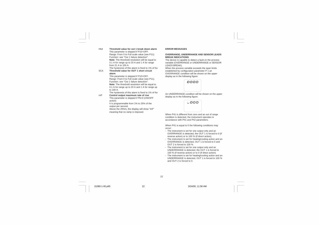
OVERRANGE, UNDERRANGE AND SENSOR LEADSBREAK INDICATIONSThe device is capable to detect a fault on the processvariable (OVERRANGE or UNDERRANGE or SENSORLEADS BREAK).When the process variable exceeds the span limitsestablished by configuration parameter P 1 anOVERRANGE condition will be shown on the upperdisplay as in the following figure:
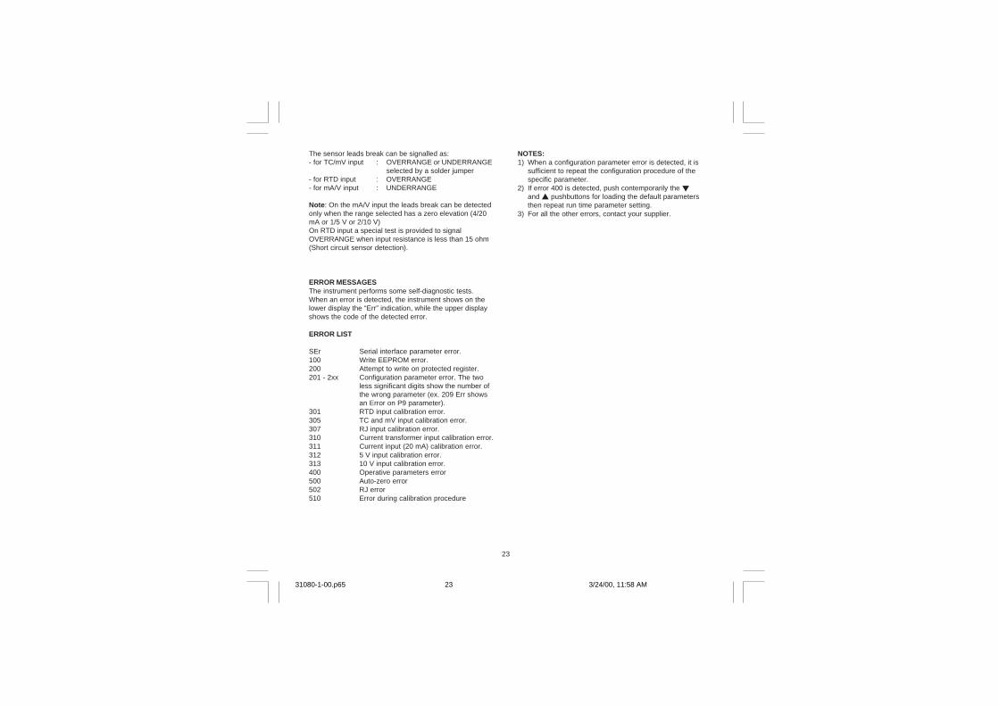
An UNDERRANGE condition will be shown on the upperdisplay as in the following figure:
When P41 is different from zero and an out of rangecondition is detected, the instrument operates inaccordance with P41 and P42 parameters.
When P41 is equal to 0 the following conditions mayoccur:- The instrument is set for one output only and an
OVERRANGE is detected, the OUT 1 is forced to 0 (ifreverse action) or to 100 % (if direct action).
- The instrument is set for heating/cooling action and anOVERRANGE is detected, OUT 1 is forced to 0 andOUT 2 is forced to 100 %.
- The instrument is set for one output only and anUNDERRANGE is detected, the OUT 1 is forced to100 % (if reverse action) or to 0 (if direct action).
- The instrument is set for heating/cooling action and anUNDERRANGE is detected, OUT 1 is forced to 100 %and OUT 2 is forced to 0.
31080-1-00.p65 3/24/00, 11:58 AM22
23
The sensor leads break can be signalled as:- for TC/mV input : OVERRANGE or UNDERRANGE
selected by a solder jumper- for RTD input : OVERRANGE- for mA/V input : UNDERRANGE
Note : On the mA/V input the leads break can be detectedonly when the range selected has a zero elevation (4/20mA or 1/5 V or 2/10 V)On RTD input a special test is provided to signalOVERRANGE when input resistance is less than 15 ohm(Short circuit sensor detection).
ERROR MESSAGESThe instrument performs some self-diagnostic tests.When an error is detected, the instrument shows on thelower display the “Err” indication, while the upper displayshows the code of the detected error.
ERROR LIST
SEr Serial interface parameter error.100 Write EEPROM error.200 Attempt to write on protected register.201 - 2xx Configuration parameter error. The two
less significant digits show the number ofthe wrong parameter (ex. 209 Err showsan Error on P9 parameter).
301 RTD input calibration error.305 TC and mV input calibration error.307 RJ input calibration error.310 Current transformer input calibration error.311 Current input (20 mA) calibration error.312 5 V input calibration error.313 10 V input calibration error.400 Operative parameters error500 Auto-zero error502 RJ error510 Error during calibration procedure
NOTES:1) When a configuration parameter error is detected, it is
sufficient to repeat the configuration procedure of thespecific parameter.
2) If error 400 is detected, push contemporarily the tand s pushbuttons for loading the default parametersthen repeat run time parameter setting.
3) For all the other errors, contact your supplier.
31080-1-00.p65 3/24/00, 11:58 AM23
24
GENERAL INFORMATIONS
GENERAL SPECIFICATIONSCase: PC black color;self-extinguishing degree: according to UL 746CFront protection - designed and tested for IP 65 andNEMA 4X for indoor locations (when panel gasket isinstalled).Test were performed in accordance with CEI 70-1 andNEMA 250-1991 STD.Weight : 360 g.Power consumption : 5.5 W max.Insulation resistance : > 100 MW according toIEC 1010-1.Dielectric strength : 2300 V rms according toEN 61010-1.Display updating time : 500 ms.Sampling time: 250 ms for linear inputs
500 ms for TC and RTD inputs.Resolution : 30000 counts.Accuracy : + 0.2% f.s.v. + 1 digit @ 25 °C ambient tempera-ture and nominal power supply voltage.Common mode rejection : 120 dB at 50/60 Hz.Normal mode rejection: 60 dB at 50/60 Hz.Electromagnetic compatibility and safety require-ments : This instrument is marked CE.Therefore, it is conforming to council directives 89/336/EEC (reference harmonized standard EN 50081-2 andEN 50082-2) and to council directives 73/23/EEC and93/68/EEC (reference harmonized standard EN 61010-1).Installation category : IIPollution degree : 2Temperature drift : (CJ excluded)< 200 ppm/°C of span for mV and TC ranges 1, 3, 5, 6, 19,
20, 21, 22.< 300 ppm/°C of span for mA/V< 400 ppm/°C of span for RTD range 10, 26 and TC range
0, 2, 4, 27 and 28.< 500 ppm/°C of span for RTD range 9 and TC ranges 7,
8, 23, 24.< 800 ppm/°C of span for RTD range 25.Operative temperature : from 0 to 50 °C.Storage temperature : -20 to +70 °CHumidity : from 20 % to 85% RH, non condensing.
Protections :1) WATCH DOG circuit for automatic restart.2) DIP SWITCH for protection against tampering ofconfiguration and calibration parameters.Control output updating time :- 250 ms when a linear input is selected- 500 ms when a TC or RTD input is selected.
MAINTENANCE1) REMOVE POWER FROM THE POWER SUPPLY
TERMINALS AND FROM RELAY OUTPUTTERMINALS
2) Remove the instrument from case.3) Using a vacuum cleaner or a compressed air jet (max.
3 kg/cm2) remove all deposit of dust and dirt whichmay be present on the louvers and on the internalcircuits trying to be careful for not damage theelectronic components.
4) To clean external plastic or rubber parts use only acloth moistened with:- Ethyl Alcohol (pure or denatured) [C
2H
5OH] or
- Isopropil Alcohol (pure or denatured) [(CH3)2CHOH]or- Water (H2O)
5) Verify that there are no loose terminals.6) Before re-inserting the instrument in its case, be sure
that it is perfectly dry.7) re-insert the instrument and turn it ON.
31080-1-00.p65 3/24/00, 11:58 AM24
Appendix A.1
APPENDIX ADEFAULT PARAMETERS
DEFAULT RUN TIME PARAMETERS
PARAMETER DEFAULT VALUESP = Initial scale valueSnRT = Disablen.SRt = OFFSP2 = Initial scale valuennn = OFFAL1 = Initial scale value for process alarm
0 for deviation or band alarmHSA1 = 0.1 %AL2 = Initial scale value for process alarm
0 for deviation or band alarmHSA2 = 0.1 %AL3 = Initial scale value for process alarm
= 0 for deviation or band alarmHSA3 = 0.1 %PB = 4.0 %HyS = 0.5 %ti = 4.00 (4 minutes)td = 1.00 (1 minute)
IP = 30 % if one control output isconfigured
= 0 if two control outputs areconfigured
Cy1 = 15 seconds for relay output= 4 seconds for SSR output
Cy2 = 10 seconds for P8 = AIr= 4 seconds for P8 = OIL= 2 seconds for P8 = H2O
rC = 1.00 for P8 = AIr= 0.80 for P8 = OIL= 0.40 for P8 = H2O
OLAP = 0rL = Initial scale valuerH = Full scale valueGrd 1 = Infinite (step transfer)Grd 2 = Infinite (step transfer)OLH = 100 %tOL = InfiniteHbd = 50 % of the full scale valueSCA = 100% of the full scale valuernP = Infinite
31080-A-00.p65 3/24/00, 11:58 AM1
Appendix A.2
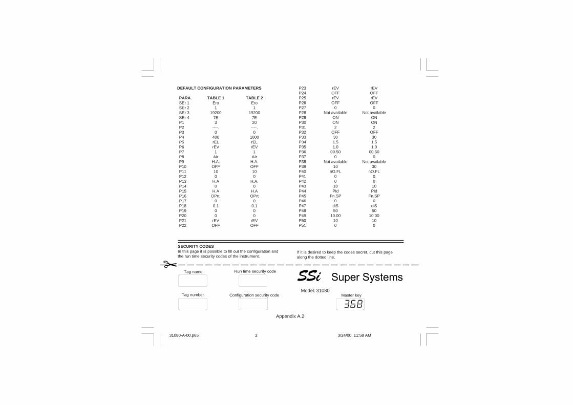
DEFAULT CONFIGURATION PARAMETERS
PARA . TABLE 1 TABLE 2SEr 1 Ero EroSEr 2 1 1SEr 3 19200 19200SEr 4 7E 7EP1 3 20P2 ----. ----.P3 0 0P4 400 1000P5 rEL rELP6 rEV rEVP7 1 1P8 AIr AIrP9 H.A. H.A.P10 OFF OFFP11 10 10P12 0 0P13 H.A H.A.P14 0 0P15 H.A H.AP16 OPrt. OPrtP17 0 0P18 0.1 0.1P19 0 0P20 0 0P21 rEV rEVP22 OFF OFF
P23 rEV rEVP24 OFF OFFP25 rEV rEVP26 OFF OFFP27 0 0P28 Not available Not availableP29 ON ONP30 ON ONP31 2 2P32 OFF OFFP33 30 30P34 1.5 1.5P35 1.0 1.0P36 00.50 00.50P37 0 0P38 Not available Not availableP39 10 30P40 nO.FL nO.FLP41 0 0P42 0 0P43 10 10P44 PId PIdP45 Fn.SP Fn.SPP46 0 0P47 diS diSP48 50 50P49 10.00 10.00P50 10 10P51 0 0
SECURITY CODESIn this page it is possible to fill out the configuration andthe run time security codes of the instrument.
Tag name
Tag number
Run time security code
Configuration security code Master keyModel: 31080
If it is desired to keep the codes secret, cut this pagealong the dotted line.
31080-A-00.p65 3/24/00, 11:58 AM2

Appendix A.3
31080-A-00.p65 3/24/00, 12:03 PM3

Super Systems Inc.4250 Creek RdCincinnati, OH 452411-800-666-4330http://www.supersystems.com
���������� ���������������
170.IU0.XKR.S00
31080-A-00.p65 4/5/00, 6:14 PM4