Embed Size (px)
Citation preview
BA_FSV_EN_12 Datum: 2011-11-15Edition: Rev. 03/11.2011
BA_FSV_EN_12
Instruction ManualFire PROtec
Cop
yrig
ht b
y S
IMO
N R
WA
Sys
tem
e G
mbH
Sub
ject
to te
chni
cal c
hang
es a
nd e
rror
s.
Instruction Manual Fire PROtecBA_FSV_EN_12 BA_FSV_EN_12Instruction manual for automatic textile Fire curtains.
Valid for following item numbers:• FSV 53011• FSV 53021• FSV 53031• FSV 53041

BA_FSV_EN_12 Date: 2011-11-15 Edition: Rev. 03/11.2011
Table of contents
Instruction ManualFire PROtec
1. Table of contents
1. Table of contents .............................................................................................................................................2
2. General ...........................................................................................................................................................4
2.1 Forward to this manual ............................................................................................................................4
2.2 Description of product .............................................................................................................................4
2.3 Intended Use ...........................................................................................................................................4
2.4 Technical data .........................................................................................................................................5
2.4.1 Fire curtain ......................................................................................................................................5
3. Safety regulations ...........................................................................................................................................5
3.1 Variants ...................................................................................................................................................6
4. Figures ............................................................................................................................................................7
5. Installation .......................................................................................................................................................9
5.1 Installation variants ................................................................................................................................10
5.1.1 Fixing to the ceiling .......................................................................................................................10
5.1.2 Fixing to the wall ...........................................................................................................................10
5.2 Install head box .....................................................................................................................................10
5.2.1 Installation of “single-piece” head box ..........................................................................................11
5.2.2 Installation of “two-piece” head box ..............................................................................................11
5.3 Installing roller assembly .......................................................................................................................13
5.4 Complete the installation .......................................................................................................................14
5.5 Install side guides ..................................................................................................................................18
5.6 Installing suspended ceiling stop unit (optional) ....................................................................................22
6. Start up ..........................................................................................................................................................22
6.1 Attach installation retainer .....................................................................................................................22
7. Care and maintenance ..................................................................................................................................23
7.1 Functional check ...................................................................................................................................23
7.2 Maintenance ..........................................................................................................................................23
7.3 Clean curtain material ...........................................................................................................................23
7.4 Repair and exchange ............................................................................................................................23
7.5 Warranty conditions ...............................................................................................................................23
7.6 Maintenance check list ..........................................................................................................................24
8. Appendix .......................................................................................................................................................25

BA_FSV_EN_12 Date: 2011-11-15Edition: Rev. 03/11.2011
Table of contents
Instruction ManualFire PROtec
Page 3
8.1 Declarations ..........................................................................................................................................25
8.1.1 EC Manufacturer’s declaration .....................................................................................................25
8.1.2 Declaration of conformity ..............................................................................................................25
8.2 Company addresses .............................................................................................................................25
8.2.1 Germany: ......................................................................................................................................25
8.2.2 Austria: ..........................................................................................................................................25
8.2.3 Switzerland: ..................................................................................................................................25
8.2.4 Hungary ........................................................................................................................................25
8.3 Notes .....................................................................................................................................................26
Fire PROtec
BA_FSV_EN_12 Date: 2011-11-15 Edition: Rev. 03/11.2011
General
Instruction ManualFire PROtec
Instruction ManualFire PROtecBA_FSV_EN_122. General
2.1 Forward to this manual
This manual has been created for the purposes of pro-per operation, installation and maintenance by trained, experienced specialist personnel (e.g. electrician) and/or specialist personnel with knowledge involving the in-stallation of electrical devices.
Read the instruction manual carefully and follow the prescribed sequence. Retain the operating manual for later use/maintenance. Please precisely observe the pin assignment, the minimum and maximum perfor-mance data (see „Technical data“) and the installation instructions. Incorrect usage or improper operation/as-sembly can cause the loss of system functions and re-sult in damage to property and/or persons.
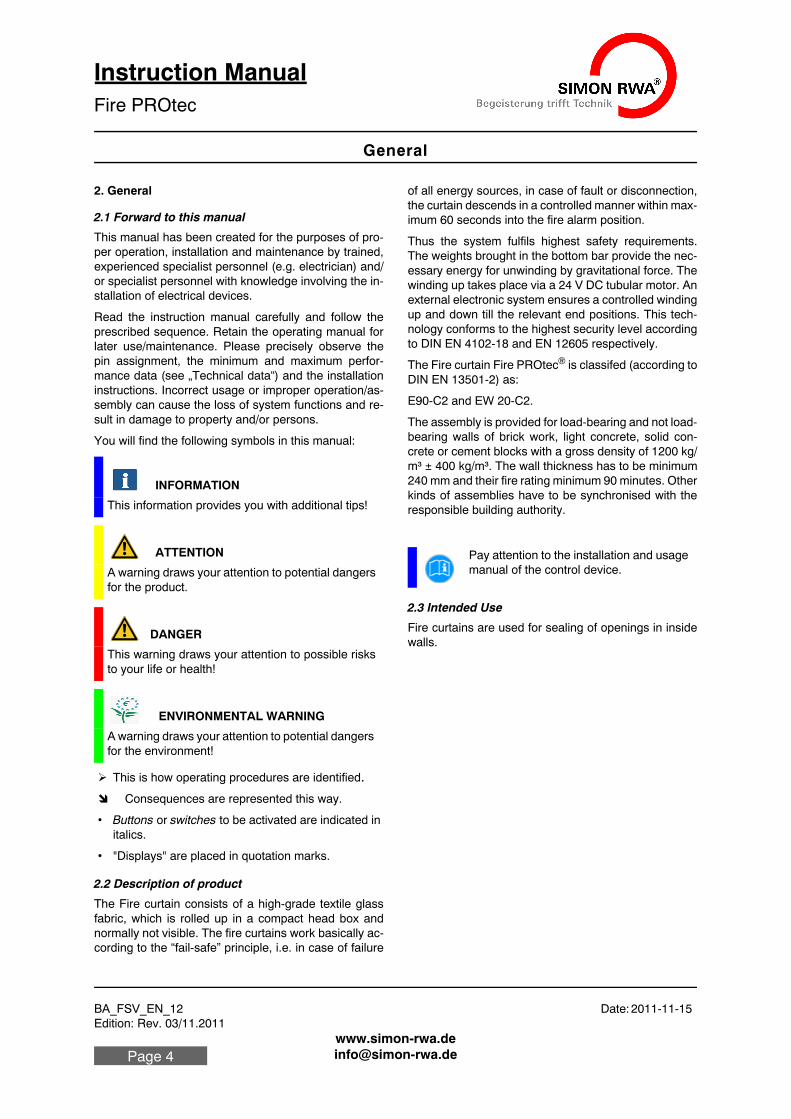
You will find the following symbols in this manual:
This is how operating procedures are identified. Consequences are represented this way.
• Buttons or switches to be activated are indicated in italics.
• "Displays" are placed in quotation marks.
2.2 Description of product
The Fire curtain consists of a high-grade textile glass fabric, which is rolled up in a compact head box and normally not visible. The fire curtains work basically ac-cording to the “fail-safe” principle, i.e. in case of failure
of all energy sources, in case of fault or disconnection, the curtain descends in a controlled manner within max-imum 60 seconds into the fire alarm position.
Thus the system fulfils highest safety requirements. The weights brought in the bottom bar provide the nec-essary energy for unwinding by gravitational force. The winding up takes place via a 24 V DC tubular motor. An external electronic system ensures a controlled winding up and down till the relevant end positions. This tech-nology conforms to the highest security level according to DIN EN 4102-18 and EN 12605 respectively.
The Fire curtain Fire PROtec® is classifed (according to DIN EN 13501-2) as:
E90-C2 and EW 20-C2.
The assembly is provided for load-bearing and not load-bearing walls of brick work, light concrete, solid con-crete or cement blocks with a gross density of 1200 kg/m³ ± 400 kg/m³. The wall thickness has to be minimum 240 mm and their fire rating minimum 90 minutes. Other kinds of assemblies have to be synchronised with the responsible building authority.
2.3 Intended Use
Fire curtains are used for sealing of openings in inside walls.
INFORMATION
This information provides you with additional tips!
ATTENTION
A warning draws your attention to potential dangers for the product.
DANGER
This warning draws your attention to possible risks to your life or health!
ENVIRONMENTAL WARNING
A warning draws your attention to potential dangers for the environment!
Pay attention to the installation and usage manual of the control device.
BA_FSV_EN_12 Date: 2011-11-15Edition: Rev. 03/11.2011
Safety regulations
Instruction ManualFire PROtec
Page 5
2.4 Technical data
2.4.1 Fire curtain
3. Safety regulations
Table 1: technical data fire curtain
Fabric One-sided PU-coated glass fabric, 660 g/m², color grey,Non –flammable according to DIN 4102-1, A2
Unwind By force of gravity (gravity fail safe)
Windup 24 V DC motor, integrated into the winding shaft, including 2 m connec-tion cable.
Installation Ceiling, wall, vertical unwinding
System dimensions
System width ≤ 5960 mm Unwinding length ≤ 6000 mm Proved in real fire test: up to system dimensions 4800 x 3700 mm. Experts reports for bigger system dimensions are available.
Head box Sheet steel 1.0 mm powder-coated in RAL 70351
1. Special color upon request.
End section Sheet steel 1.0 mm powder-coated
in RAL 70351. with integrated unwind weights in fabric bag
Classifica-tion/Stand-ardization
DIN EN 13501-2/DIN EN 1634-1; DIN 4102-5; DIN 4102-18; DIN EN 12605
Classifica-tion
E90-C2EW 20-C2(entsprechend DIN EN 13501-2)
Side guides (SFS)
Steel 1.5 mm powder-coated in RAL 70351., dimensions (W × D) 50 × 100 mm. In case of use of side guides the curtain material will be delivered with a restraint system. In this way, it pre-vents the curtain material being pulled out sideways from the tracks in case of deflection by pressurization (e.g. excess pressure by fire):
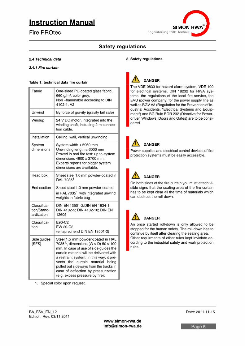
DANGER
The VDE 0833 for hazard alarm system, VDE 100 for electrical systems, DIN 18232 for RWA sys-tems, the regulations of the local fire service, the EVU (power company) for the power supply line as well as BGV A3 (Regulation for the Prevention of In-dustrial Accidents, "Electrical Systems and Equip-ment") and BG Rule BGR 232 (Directive for Power-driven Windows, Doors and Gates) are to be consi-dered
DANGER
Power supplies and electrical control devices of fire protection systems must be easily accessible.
DANGER
On both sides of the fire curtain you must attach vi-sible signs that the sealing area of the fire curtain has to be kept clear all the time of materials which can obstruct the roll-down.
DANGER
An once started roll-down is only allowed to be stopped for the human safety. The roll-down has to continue by itself after clearing the sealing area.Other requirments of other rules kept inviolate ac-cording to the industrial safety and work protection rules.
Fire PROtec
BA_FSV_EN_12 Date: 2011-11-15 Edition: Rev. 03/11.2011
Safety regulations
Instruction ManualFire PROtec
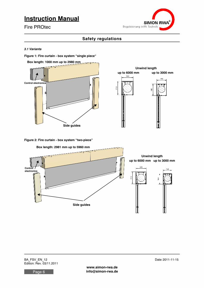
3.1 Variants
Figure 1: Fire curtain - box system “single piece“
Figure 2: Fire curtain - box system “two-piece”
Unwind lengthup to 6000 mm up to 3000 mm
Box length: 1000 mm up to 2980 mm
Side guides
Control electronics
Side guides
Unwind lengthup to 6000 mm up to 3000 mm
Box length: 2981 mm up to 5960 mm
Controlelectronics
BA_FSV_EN_12 Date: 2011-11-15Edition: Rev. 03/11.2011
Figures
Instruction ManualFire PROtec
Page 7
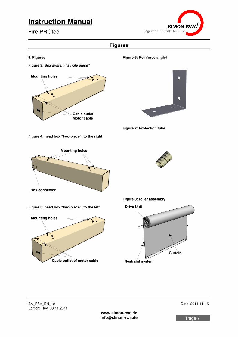
4. Figures
Figure 3: Box system “single piece”
Figure 4: head box “two-piece”, to the right
Figure 5: head box “two-piece”, to the left
Figure 6: Reinforce anglel
Figure 7: Protection tube
Figure 8: roller assembly
Cable outlet
Mounting holes
Motor cable
Mounting holes
Box connector
Cable outlet of motor cable
Mounting holes
Drive Unit
Curtain
Restraint system
Fire PROtec
BA_FSV_EN_12 Date: 2011-11-15 Edition: Rev. 03/11.2011
Figures
Instruction ManualFire PROtec
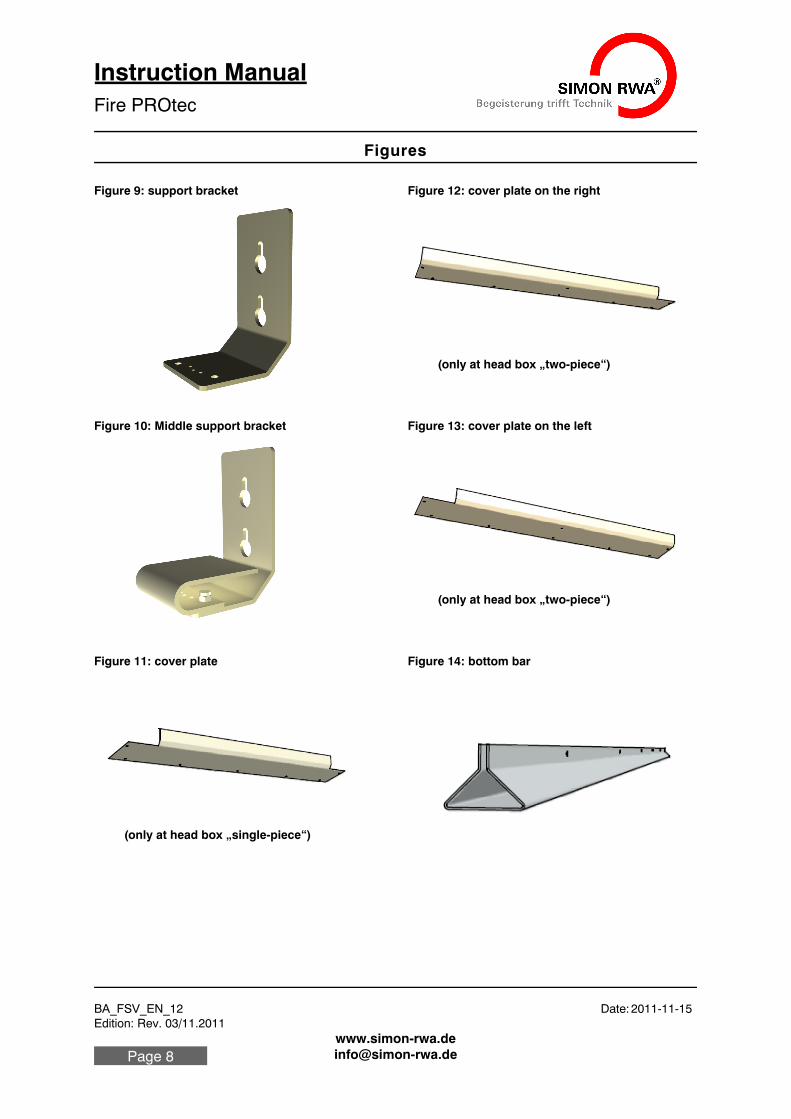
Figure 9: support bracket
Figure 10: Middle support bracket
Figure 11: cover plate
Figure 12: cover plate on the right
Figure 13: cover plate on the left
Figure 14: bottom bar
(only at head box „two-piece“)
(only at head box „single-piece“)
(only at head box „two-piece“)
(only at head box „two-piece“)
BA_FSV_EN_12 Date: 2011-11-15Edition: Rev. 03/11.2011
Installation
Instruction ManualFire PROtec
Page 9
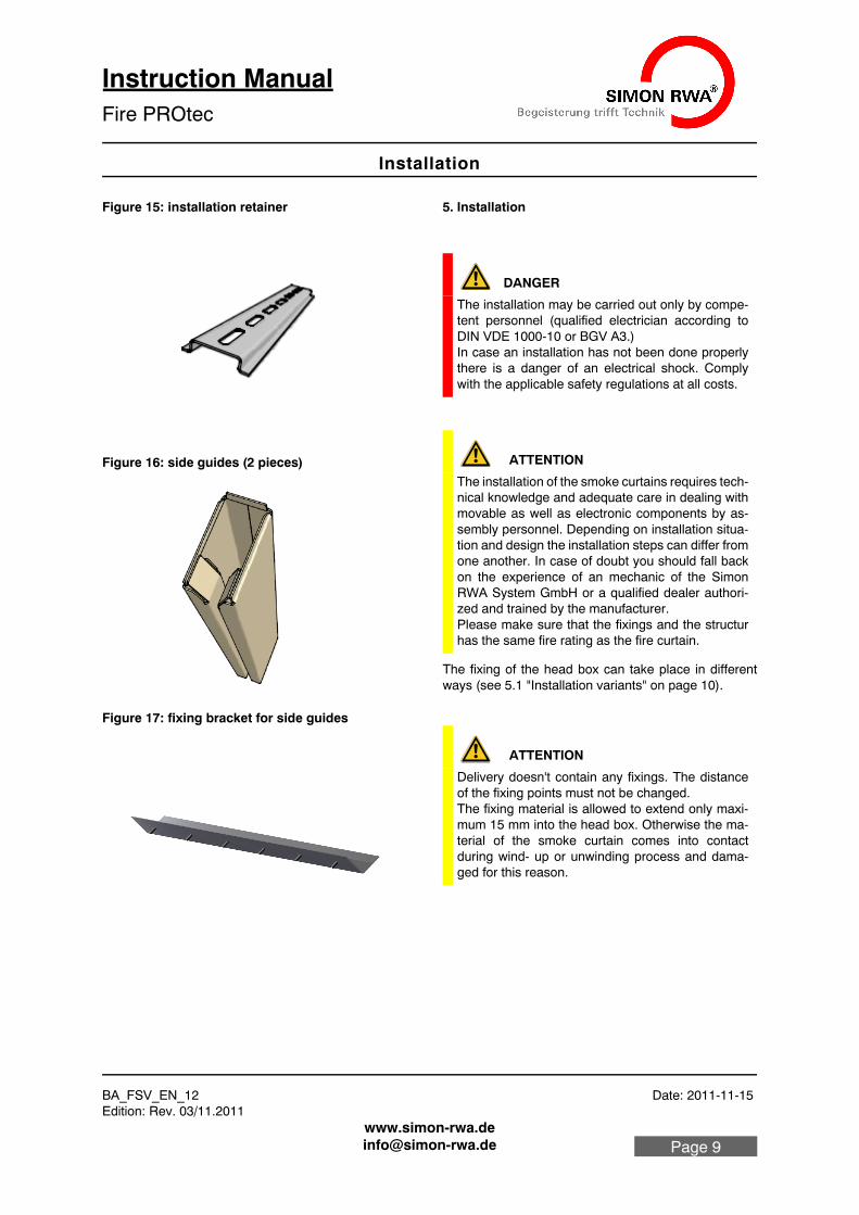
Figure 15: installation retainer
Figure 16: side guides (2 pieces)
Figure 17: fixing bracket for side guides
5. Installation
The fixing of the head box can take place in different ways (see 5.1 "Installation variants" on page 10).
DANGER
The installation may be carried out only by compe-tent personnel (qualified electrician according to DIN VDE 1000-10 or BGV A3.)In case an installation has not been done properly there is a danger of an electrical shock. Comply with the applicable safety regulations at all costs.
ATTENTION
The installation of the smoke curtains requires tech-nical knowledge and adequate care in dealing with movable as well as electronic components by as-sembly personnel. Depending on installation situa-tion and design the installation steps can differ from one another. In case of doubt you should fall back on the experience of an mechanic of the Simon RWA System GmbH or a qualified dealer authori-zed and trained by the manufacturer.Please make sure that the fixings and the structur has the same fire rating as the fire curtain.
ATTENTION
Delivery doesn't contain any fixings. The distance of the fixing points must not be changed. The fixing material is allowed to extend only maxi-mum 15 mm into the head box. Otherwise the ma-terial of the smoke curtain comes into contact during wind- up or unwinding process and dama-ged for this reason.
Fire PROtec
BA_FSV_EN_12 Date: 2011-11-15 Edition: Rev. 03/11.2011
Installation
Instruction ManualFire PROtec
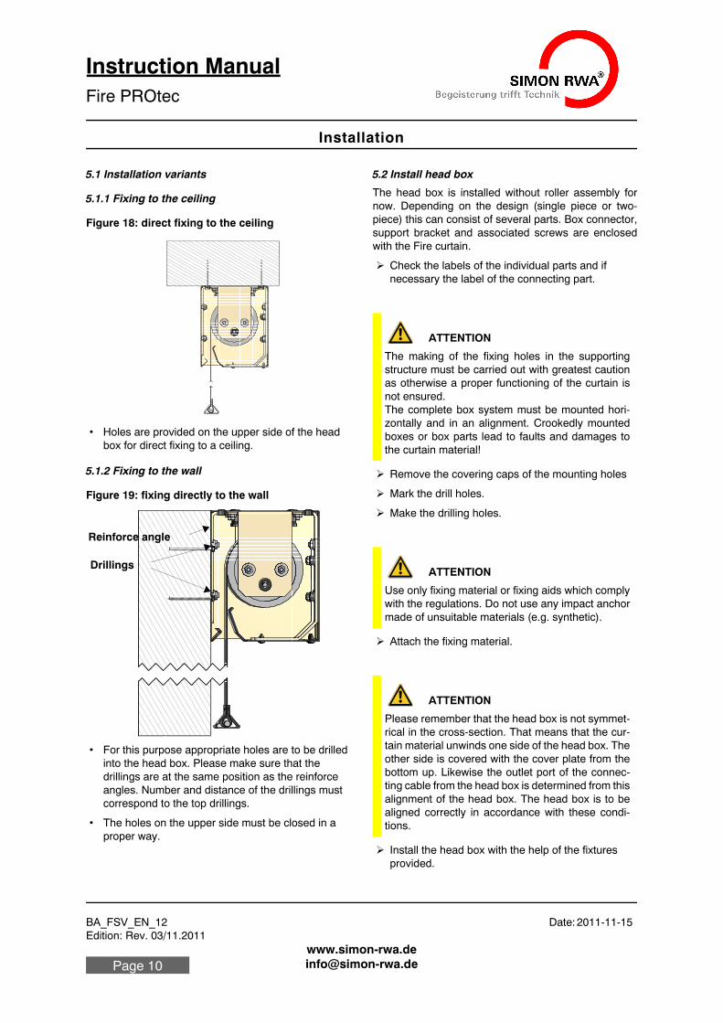
5.1 Installation variants
5.1.1 Fixing to the ceiling
Figure 18: direct fixing to the ceiling
• Holes are provided on the upper side of the head box for direct fixing to a ceiling.
5.1.2 Fixing to the wall
Figure 19: fixing directly to the wall
• For this purpose appropriate holes are to be drilled into the head box. Please make sure that the drillings are at the same position as the reinforce angles. Number and distance of the drillings must correspond to the top drillings.
• The holes on the upper side must be closed in a proper way.
5.2 Install head box
The head box is installed without roller assembly for now. Depending on the design (single piece or two-piece) this can consist of several parts. Box connector, support bracket and associated screws are enclosed with the Fire curtain.
Check the labels of the individual parts and if necessary the label of the connecting part.
Remove the covering caps of the mounting holes
Mark the drill holes.
Make the drilling holes.
Attach the fixing material.
Install the head box with the help of the fixtures provided.
Drillings
Reinforce angle
ATTENTION
The making of the fixing holes in the supporting structure must be carried out with greatest caution as otherwise a proper functioning of the curtain is not ensured. The complete box system must be mounted hori-zontally and in an alignment. Crookedly mounted boxes or box parts lead to faults and damages to the curtain material!
ATTENTION
Use only fixing material or fixing aids which comply with the regulations. Do not use any impact anchor made of unsuitable materials (e.g. synthetic).
ATTENTION
Please remember that the head box is not symmet-rical in the cross-section. That means that the cur-tain material unwinds one side of the head box. The other side is covered with the cover plate from the bottom up. Likewise the outlet port of the connec-ting cable from the head box is determined from this alignment of the head box. The head box is to be aligned correctly in accordance with these condi-tions.
BA_FSV_EN_12 Date: 2011-11-15Edition: Rev. 03/11.2011
Installation
Instruction ManualFire PROtec
Page 11
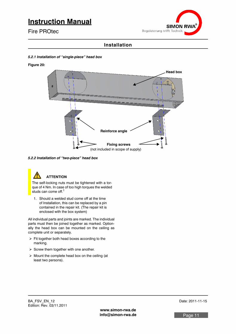
5.2.1 Installation of “single-piece” head box
Figure 20:
5.2.2 Installation of “two-piece” head box
All individual parts and joints are marked. The individual parts must then be joined together as marked. Option-ally the head box can be mounted on the ceiling as complete unit or separately.
Fit together both head boxes according to the marking.
Screw them together with one another.
Mount the complete head box on the ceiling (at least two persons).
Fixing screws (not included in scope of supply)
Reinforce angle
Head box
ATTENTION
The self-locking nuts must be tightened with a tor-que of 4 Nm. In case of too high torques the welded studs can come off.1
1. Should a welded stud come off at the time of Installation, this can be replaced by a pin contained in the repair kit. (The repair kit is enclosed with the box system)
Fire PROtec
BA_FSV_EN_12 Date: 2011-11-15 Edition: Rev. 03/11.2011
Installation
Instruction ManualFire PROtec
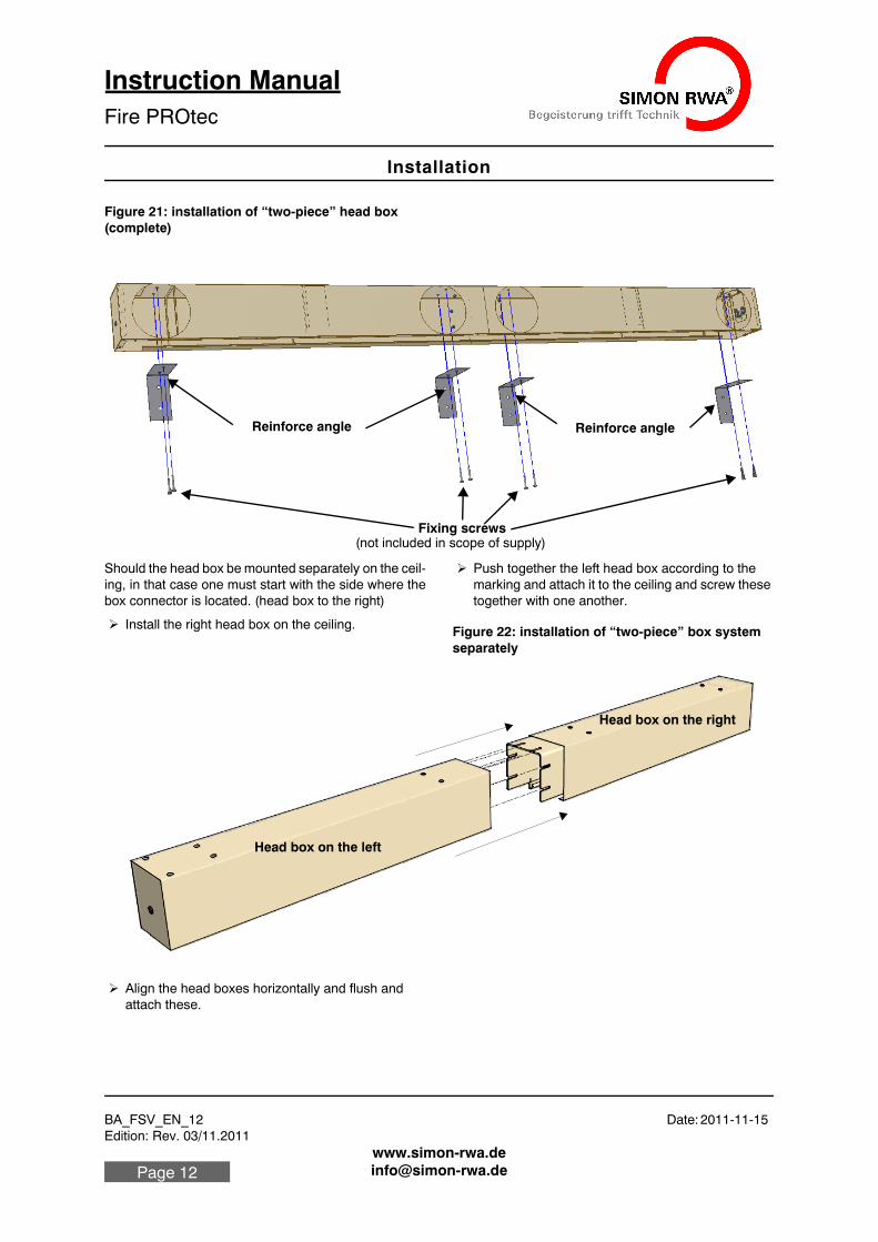
Figure 21: installation of “two-piece” head box (complete)
Should the head box be mounted separately on the ceil-ing, in that case one must start with the side where the box connector is located. (head box to the right)
Install the right head box on the ceiling.
Push together the left head box according to the marking and attach it to the ceiling and screw these together with one another.
Figure 22: installation of “two-piece” box system separately
Align the head boxes horizontally and flush and attach these.
Fixing screws (not included in scope of supply)
Reinforce angle Reinforce angle
Head box on the left
Head box on the right
BA_FSV_EN_12 Date: 2011-11-15Edition: Rev. 03/11.2011
Installation
Instruction ManualFire PROtec
Page 13
Use the same procedure for the mounting on the wall, as already described (see “Fixing to the ceiling” up to 10).
5.3 Installing roller assembly
Insert roller assembly into the head box with the help of a second person (or suitable lifting devices).
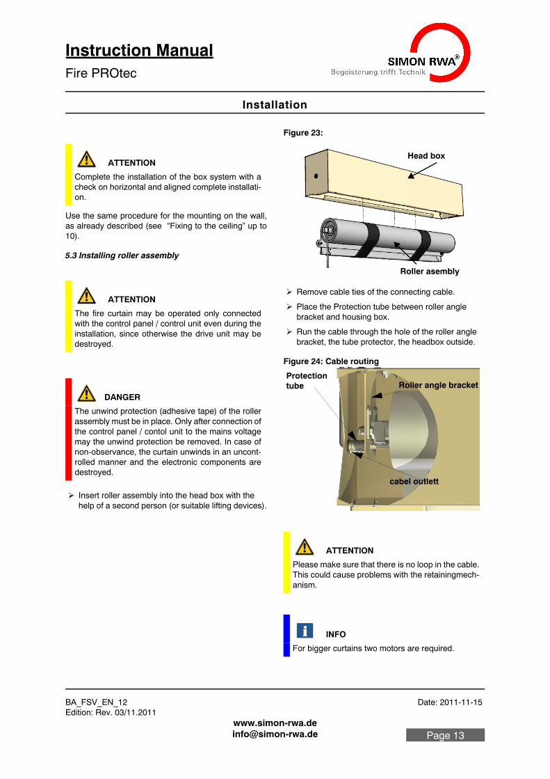
Figure 23:
Remove cable ties of the connecting cable.
Place the Protection tube between roller angle bracket and housing box.
Run the cable through the hole of the roller angle bracket, the tube protector, the headbox outside.
Figure 24: Cable routing
ATTENTION
Complete the installation of the box system with a check on horizontal and aligned complete installati-on.
ATTENTION
The fire curtain may be operated only connected with the control panel / control unit even during the installation, since otherwise the drive unit may be destroyed.
DANGER
The unwind protection (adhesive tape) of the roller assembly must be in place. Only after connection of the control panel / contol unit to the mains voltage may the unwind protection be removed. In case of non-observance, the curtain unwinds in an uncont-rolled manner and the electronic components are destroyed.
ATTENTION
Please make sure that there is no loop in the cable. This could cause problems with the retainingmech-anism.
INFO
For bigger curtains two motors are required.
Head box
Roller asembly
cabel outlett
ProtectionRoller angle brackettube
Fire PROtec
BA_FSV_EN_12 Date: 2011-11-15 Edition: Rev. 03/11.2011
Installation
Instruction ManualFire PROtec
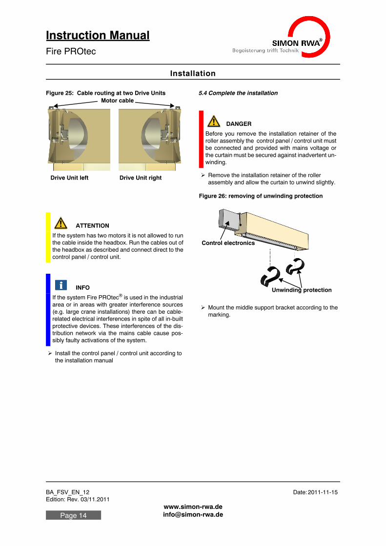
Figure 25: Cable routing at two Drive Units
Install the control panel / control unit according to the installation manual
5.4 Complete the installation
Remove the installation retainer of the roller assembly and allow the curtain to unwind slightly.
Figure 26: removing of unwinding protection
Mount the middle support bracket according to the marking.
ATTENTION
If the system has two motors it is not allowed to run the cable inside the headbox. Run the cables out of the headbox as described and connect direct to the control panel / control unit.
INFO
If the system Fire PROtec® is used in the industrial area or in areas with greater interference sources (e.g. large crane installations) there can be cable-related electrical interferences in spite of all in-built protective devices. These interferences of the dis-tribution network via the mains cable cause pos-sibly faulty activations of the system.
Drive Unit left Drive Unit right
Motor cable
DANGER
Before you remove the installation retainer of the roller assembly the control panel / control unit must be connected and provided with mains voltage or the curtain must be secured against inadvertent un-winding.
Unwinding protection
Control electronics
BA_FSV_EN_12 Date: 2011-11-15Edition: Rev. 03/11.2011
Installation
Instruction ManualFire PROtec
Page 15
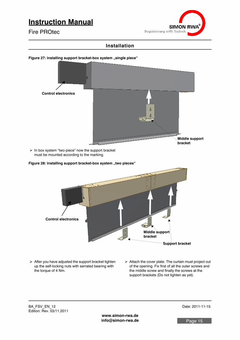
Figure 27: installing support bracket-box system „single piece“
In box system “two-piece” now the support bracket must be mounted according to the marking.
Figure 28: installing support bracket-box system „two pieces“
After you have adjusted the support bracket tighten up the self-locking nuts with serrated bearing with the torque of 4 Nm.
Attach the cover plate. The curtain must project out of the opening. Fix first of all the outer screws and the middle screw and finally the screws at the support brackets (Do not tighten as yet).
Middle supportbracket
Control electronics
Support bracket
Middle supportbracket
Control electronics
Fire PROtec
BA_FSV_EN_12 Date: 2011-11-15 Edition: Rev. 03/11.2011
Installation
Instruction ManualFire PROtec
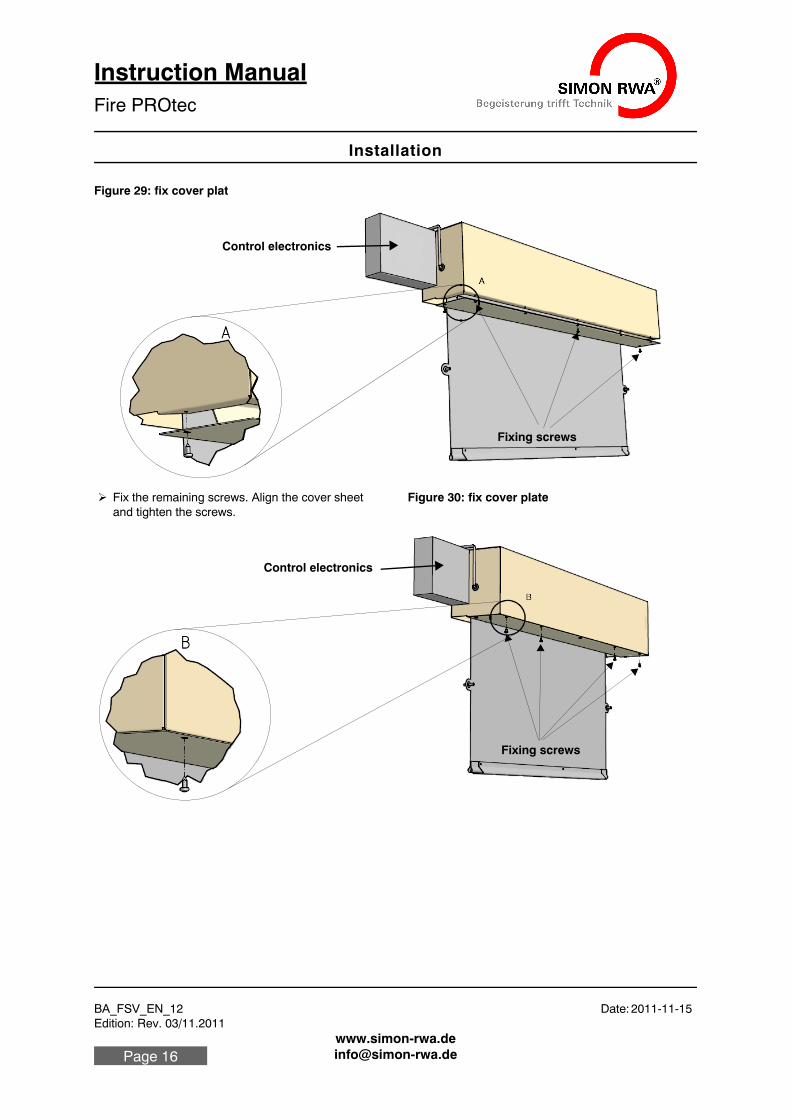
Figure 29: fix cover plat
Fix the remaining screws. Align the cover sheet and tighten the screws.
Figure 30: fix cover plate
Fixing screws
Control electronics
Fixing screws
Control electronics
BA_FSV_EN_12 Date: 2011-11-15Edition: Rev. 03/11.2011
Installation
Instruction ManualFire PROtec
Page 17
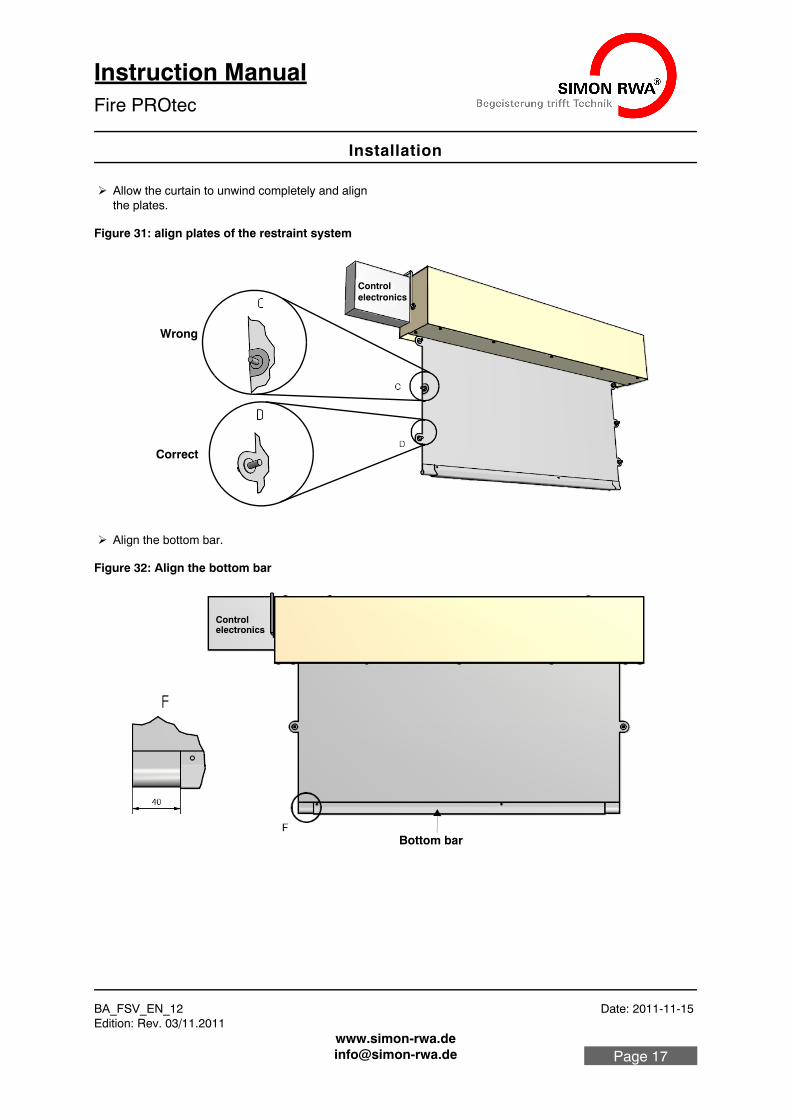
Allow the curtain to unwind completely and align the plates.
Figure 31: align plates of the restraint system
Align the bottom bar.
Figure 32: Align the bottom bar
Correct
Wrong
electronicsControl
Bottom bar
Controlelectronics
Fire PROtec
BA_FSV_EN_12 Date: 2011-11-15 Edition: Rev. 03/11.2011
Installation
Instruction ManualFire PROtec
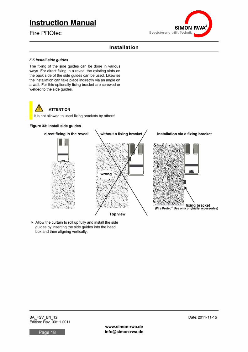
5.5 Install side guides
The fixing of the side guides can be done in various ways. For direct fixing in a reveal the existing slots on the back side of the side guides can be used. Likewise the installation can take place indirectly via an angle on a wall. For this optionally fixing bracket are screwed or welded to the side guides.
Figure 33: install side guides
Allow the curtain to roll up fully and install the side guides by inserting the side guides into the head box and then aligning vertically.
ATTENTION
It is not allowed to used fixing brackets by others!
Top view
wrong
without a fixing bracket installation via a fixing bracketdirect fixing in the reveal
fixing bracket(Fire Protec® Use only originally accessories)
BA_FSV_EN_12 Date: 2011-11-15Edition: Rev. 03/11.2011
Installation
Instruction ManualFire PROtec
Page 19
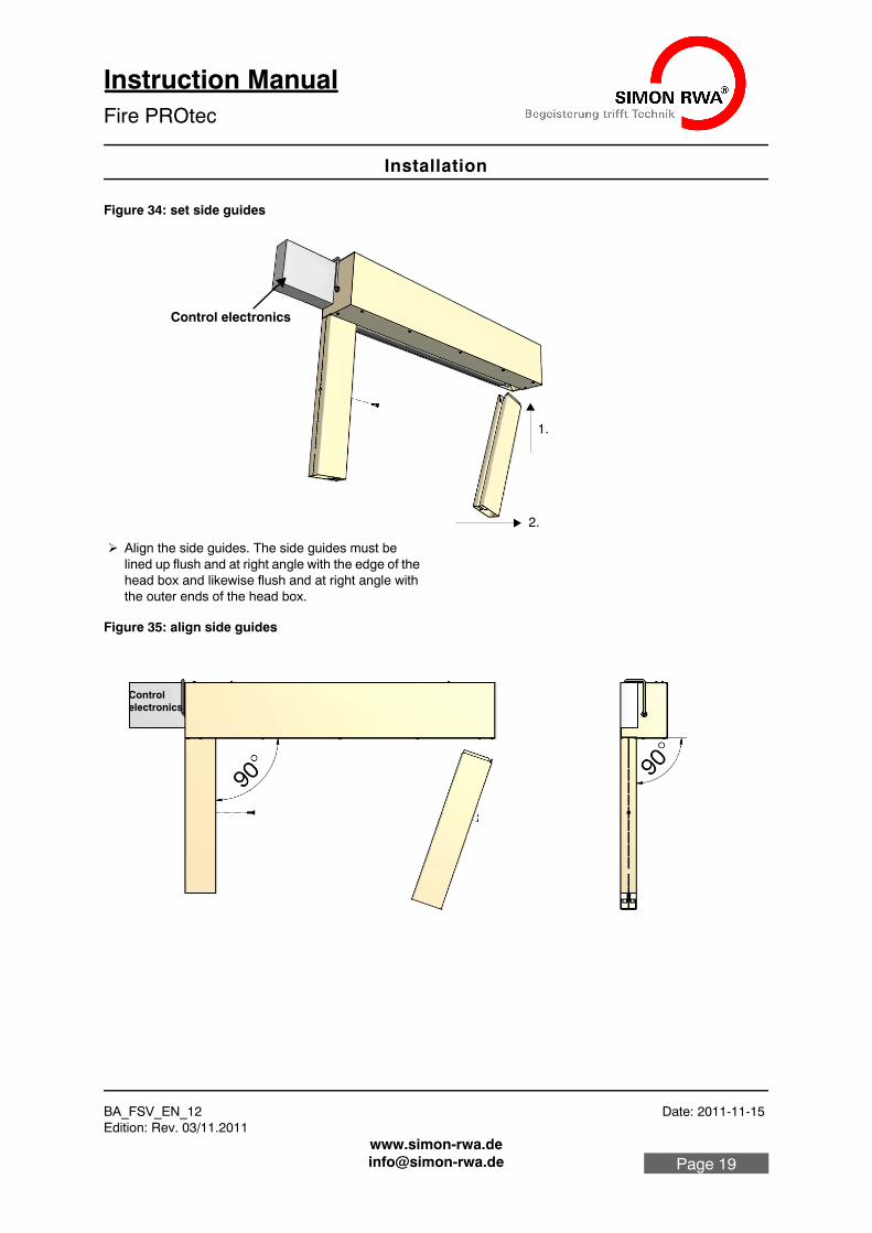
Figure 34: set side guides
Align the side guides. The side guides must be lined up flush and at right angle with the edge of the head box and likewise flush and at right angle with the outer ends of the head box.
Figure 35: align side guides
1.
2.
Control electronics
Controlelectronics
Fire PROtec
BA_FSV_EN_12 Date: 2011-11-15 Edition: Rev. 03/11.2011
Installation
Instruction ManualFire PROtec
Mark the installation holes.
Make the installation holes.
Fix the side guides.
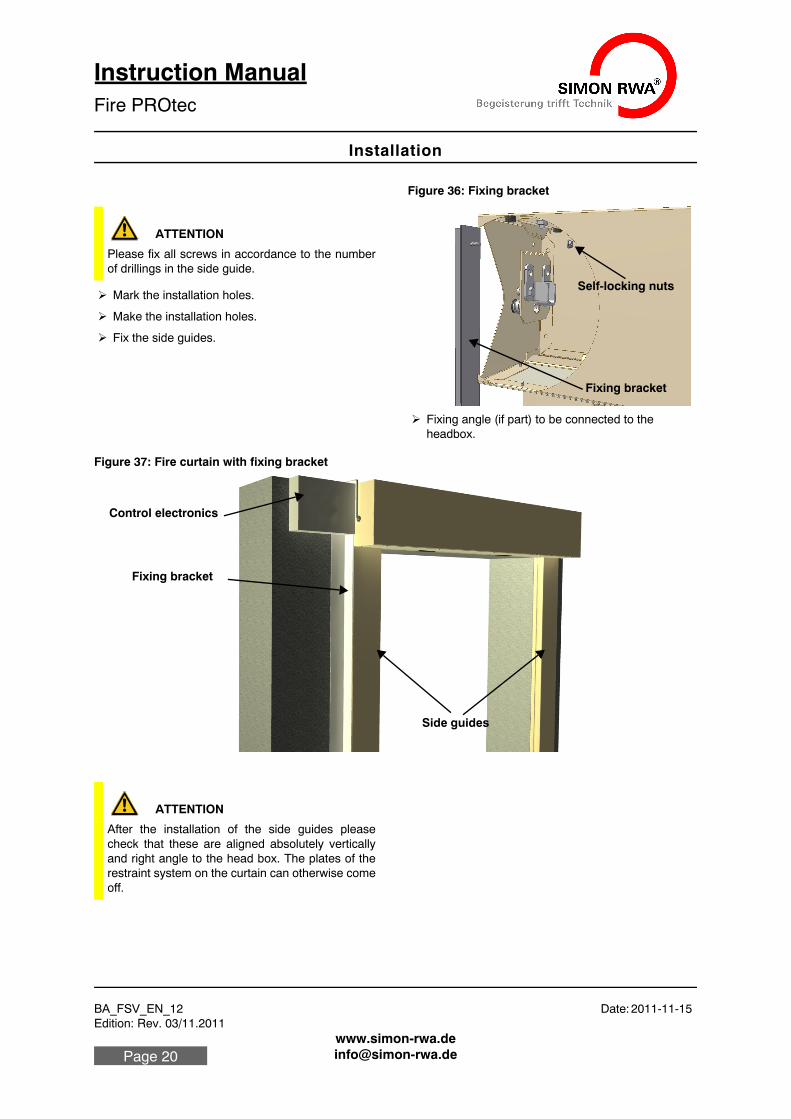
Figure 36: Fixing bracket
Fixing angle (if part) to be connected to the headbox.
Figure 37: Fire curtain with fixing bracket
ATTENTION
Please fix all screws in accordance to the number of drillings in the side guide.
Self-locking nuts
Fixing bracket
Side guides
Fixing bracket
Control electronics
ATTENTION
After the installation of the side guides please check that these are aligned absolutely vertically and right angle to the head box. The plates of the restraint system on the curtain can otherwise come off.
BA_FSV_EN_12 Date: 2011-11-15Edition: Rev. 03/11.2011
Installation
Instruction ManualFire PROtec
Page 21
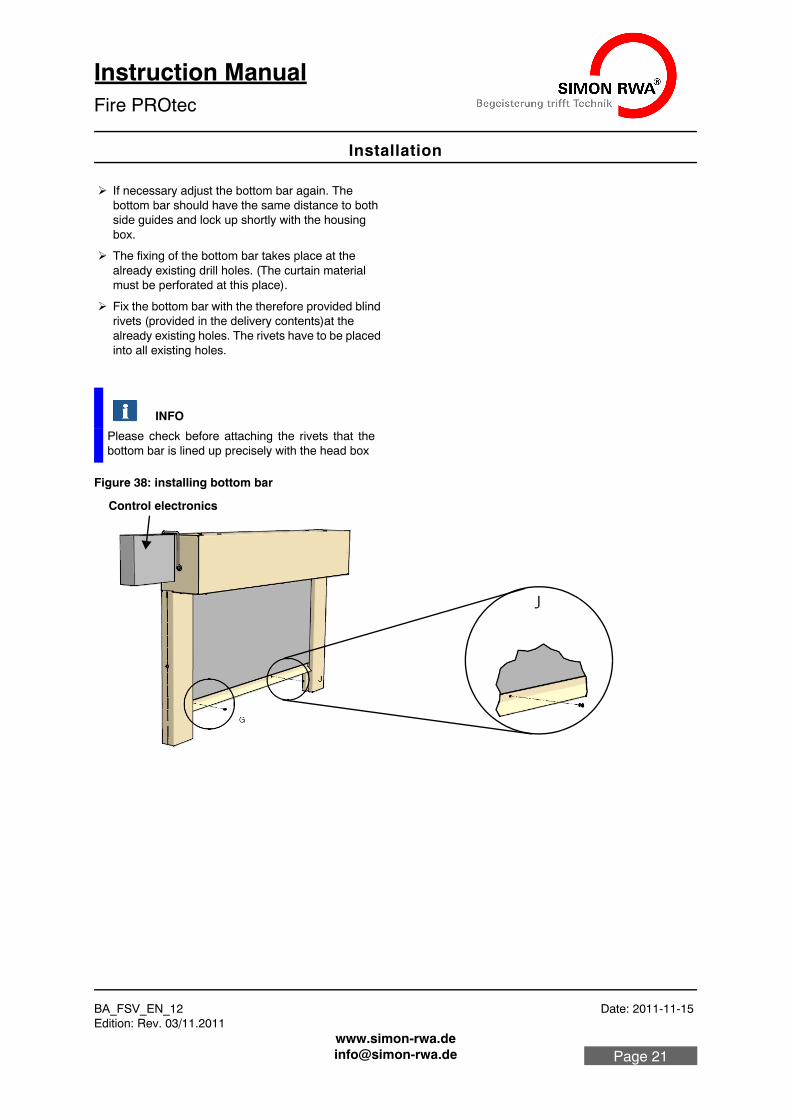
If necessary adjust the bottom bar again. The bottom bar should have the same distance to both side guides and lock up shortly with the housing box.
The fixing of the bottom bar takes place at the already existing drill holes. (The curtain material must be perforated at this place).
Fix the bottom bar with the therefore provided blind rivets (provided in the delivery contents)at the already existing holes. The rivets have to be placed into all existing holes.
Figure 38: installing bottom bar
INFO
Please check before attaching the rivets that the bottom bar is lined up precisely with the head box
Control electronics
Fire PROtec
BA_FSV_EN_12 Date: 2011-11-15 Edition: Rev. 03/11.2011
Start up
Instruction ManualFire PROtec
5.6 Installing suspended ceiling stop unit (optional)
See Installation instructions of suspended ceiling stop unit.
6. Start up
Start the initial operation (according to the installation manual of the control panel / control unit)
6.1 Attach installation retainer
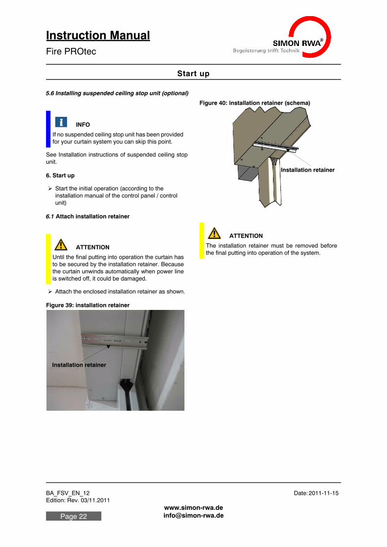
Attach the enclosed installation retainer as shown.
Figure 39: installation retainer
Figure 40: installation retainer (schema)
INFO
If no suspended ceiling stop unit has been provided for your curtain system you can skip this point.
ATTENTION
Until the final putting into operation the curtain has to be secured by the installation retainer. Because the curtain unwinds automatically when power line is switched off, it could be damaged.
Installation retainer
ATTENTION
The installation retainer must be removed before the final putting into operation of the system.
Installation retainer
BA_FSV_EN_12 Date: 2011-11-15Edition: Rev. 03/11.2011
Care and maintenance
Instruction ManualFire PROtec
Page 23
7. Care and maintenance
The fire curtain and if required the hold-on device must be kept workable all the time. It must be checked at least once a month in personal responsibility of the owner or his trained staff. The results must be noticed in a test book.
The test book must be storaged by the owner and has to be shown when required by the building control au-thority.
7.1 Functional check
The functioning of the system must be checked regular-ly by the operator. In case of a possible defect the man-ufacturing company is to be notified immediately. Damaged parts are to be replaced immediately.
The functioning of the fire curtain should be checked monthly. For this purpose the following steps are nec-essary:
• Make sure that the unwind area is always free from obstructions.
• Let the curtain unwind via manual trigger button or service button.
• Carry out a visual inspection of the attachments and material.
• Let the curtain wind up again (via reset button of the manual trigger button or service button).
• Check if the curtain winds up properly and remains in this position.
7.2 Maintenance
The maintenance is done according to a maintenance check list specified by the manufacturer (see 7.6 "Main-tenance check list" on page 24). (or download at www.simon-rwa.de).
The anual maintenance for defect free roll-down and working of the fire curtain in combination with the hold-on device must be done by a known special company. All the results has to be noticed in the test book as well.
The test book must be storaged by the owner and has to be shown when required by the building control au-thority.
7.3 Clean curtain material
7.4 Repair and exchange
The electrical control panel / control unit may be re-paired only by the manufacturer. In case of a failure the complete control panel is to be exchanged.
7.5 Warranty conditions
Concerning the warranty please refer to: “General Con-ditions for the supply of Products and Services of the Electrical and Electronics industry” (Green Terms of Delivery” – GL)”. This is available to you on our web site www.simon-rwa.de. We shall be glad to send you a copy on re-quest.
ATTENTION
In the long run the protective effect of the fire curtain is only secured if it is kept correct state (e.g. no me-chanical damage, no dirt, maintenance)
DANGER
Fire protection equipments serve to protect human lives and must therefore be serviced regularly – at least once a year – by a specialist company autho-rized by the manufacturer.
ATTENTION
The curtain material is washable with mild commer-cial disinfectant or warm water. The curtain material must not be soaked or washed by machine, since otherwise the backing fabric will be damaged and glass filaments can come off.
Fire PROtec
BA_FSV_EN_12 Date: 2011-11-15 Edition: Rev. 03/11.2011
Care and maintenance
Instruction ManualFire PROtec
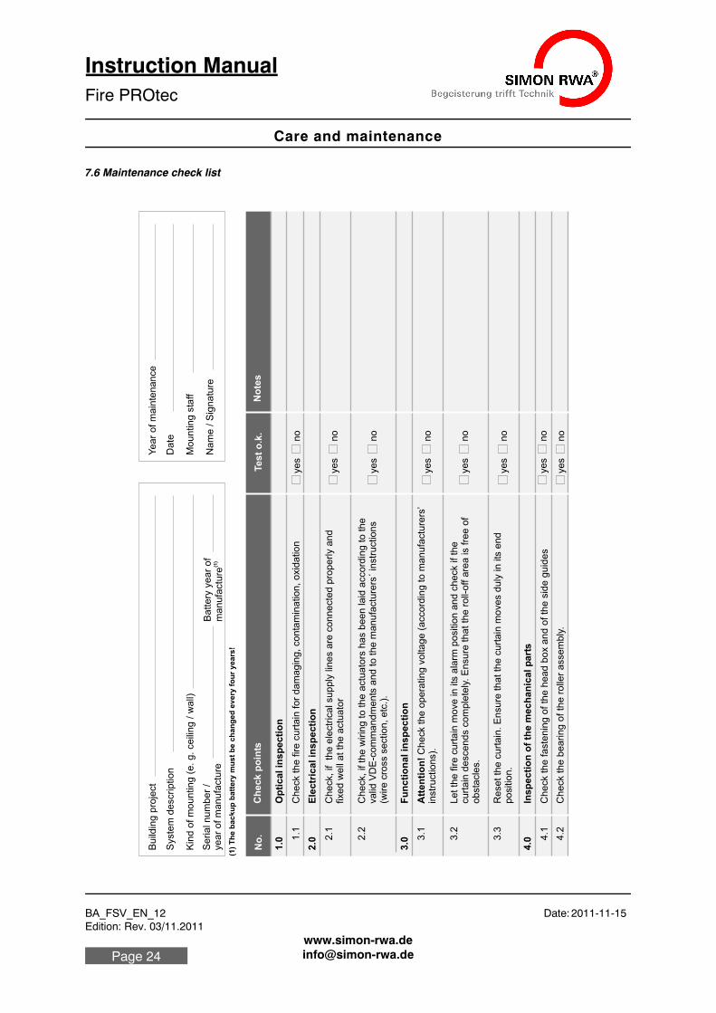
7.6 Maintenance check list
Bu
ildin
g p
roje
ct
Syste
m d
escrip
tio
n
Kin
d o
f m
ou
ntin
g (
e. g
. ce
ilin
g / w
all)
Se
ria
l n
um
be
r /
ye
ar
of m
an
ufa
ctu
re
Ye
ar
of m
ain
ten
an
ce
Da
te
Mo
un
tin
g s
taff
Na
me
/ S
ign
atu
reB
att
ery
ye
ar
of
(1)
ma
nu
factu
re
(1)
Th
e b
ac
ku
p b
att
ery
mu
st
be
ch
an
ge
d e
ve
ry f
ou
r y
ea
rs!
No
.C
he
ck
po
ints
Op
tical in
sp
ecti
on
Te
st
o.k
.N
ote
s
Ch
eck th
e fire
cu
rta
in fo
r d
am
ag
ing
, co
nta
min
atio
n, o
xid
atio
n
Ele
ctr
ica
l in
sp
ec
tio
n
Ch
eck, if th
e e
lectr
ica
l su
pp
ly lin
es a
re c
on
ne
cte
d p
rop
erly a
nd
fixe
d w
ell
at th
e a
ctu
ato
r
Ch
eck, if th
e w
irin
g to
th
e a
ctu
ato
rs h
as b
ee
n la
id a
cco
rdin
g to
th
e
va
lid V
DE
-co
mm
an
dm
en
ts a
nd
to
th
e m
an
ufa
ctu
rers
´ in
str
uctio
ns
(wire
cro
ss s
ectio
n, e
tc.)
.
Fu
ncti
on
al in
sp
ecti
on
Att
en
tio
n!
Ch
eck th
e o
pe
ratin
g v
olta
ge
(a
cco
rdin
g to
ma
nu
factu
rers
’ in
str
uctio
ns).
Le
t th
e fire
cu
rta
in m
ove
in
its
ala
rm p
ositio
n a
nd
ch
eck if th
e
cu
rta
in d
esce
nd
s c
om
ple
tely
. E
nsu
re th
at th
e r
oll-
off a
rea
is fre
e o
f o
bsta
cle
s.
Re
se
t th
e c
urt
ain
. E
nsu
re th
at th
e c
urt
ain
mo
ve
s d
uly
in
its
en
d
po
sitio
n.
Ins
pe
cti
on
of
the
me
ch
an
ica
l p
art
s
Ch
eck th
e fa
ste
nin
g o
f th
e h
ea
d b
ox a
nd
of th
e s
ide
gu
ide
s
Ch
eck th
e b
ea
rin
g o
f th
e r
olle
r a
sse
mb
ly.
1.1
2.2
1.0
2.0 2
.1
3.0 3
.1
3.2
3.3
4.0 4
.1
4.2
ye
sn
o
ye
sn
o
ye
sn
o
ye
sn
o
ye
sn
o
ye
sn
o
ye
sn
o
ye
sn
o
BA_FSV_EN_12 Date: 2011-11-15Edition: Rev. 03/11.2011
Appendix
Instruction ManualFire PROtec
Page 25
8. Appendix
8.1 Declarations
8.1.1 EC Manufacturer’s declaration
We hereby declare that for development and production of the in market product Fire PROtec® all the require-ments of DIN EN 13501-2 are fullfilled.
8.1.2 Declaration of conformity
We hereby declare the conformity of the product with the guidelines applicable for it. The declaration of con-formity can be examined in the firm and shall be sent to you on request.
Any alteration which may be made without our prior consent will make this declaration invalid.
8.2 Company addresses
8.2.1 Germany:
Simon RWA® Systeme GmbH Medienstr. 8 D - 94036 Passau Tel.: +49 (0)851 98870 - 0 Fax: +49 (0)851 98870-70 E-Mail: [email protected] Internet: www.simon-rwa.de
8.2.2 Austria:
Simon RWA® Systeme GmbH Aumühlweg 21 Top 313/314 A - 2544 Leobersdorf Tel.: +43 (0)2256 64001 Fax: +43 (0)2256 64070 E-Mail: [email protected] Internet: www.simon-rwa.at
8.2.3 Switzerland:
Simon RWA® Systeme AG Allmendstrasse 8 CH - 8320 Fehraltorf
Tel.: +41 (0)44 956 50 30 Fax: +41 (0)44 956 50 40 E-Mail: [email protected] Internet: www.simon-rwa.ch
8.2.4 Hungary
Simon RWA® Systeme Kft. Vezér uta 147 / D, III. Floor, No. 17 H - 1149 Budapest Tel.: +36 (0)44 822 12 52 Fax: +36 (0)44 822 12 03 E-Mail: [email protected]

Fire PROtec
BA_FSV_EN_12 Date: 2011-11-15 Edition: Rev. 03/11.2011
Appendix
Instruction ManualFire PROtec
8.3 Notes
___________________________________________
___________________________________________
___________________________________________
___________________________________________
___________________________________________
___________________________________________
___________________________________________
___________________________________________
___________________________________________
___________________________________________
___________________________________________
___________________________________________
___________________________________________
___________________________________________
___________________________________________
___________________________________________
___________________________________________
___________________________________________
___________________________________________
___________________________________________
___________________________________________
___________________________________________
___________________________________________
___________________________________________
___________________________________________
___________________________________________
___________________________________________
___________________________________________
___________________________________________
___________________________________________
___________________________________________
___________________________________________
___________________________________________
___________________________________________

BA_FSV_EN_12 Date: 2011-11-15Edition: Rev. 03/11.2011
Appendix
Instruction ManualFire PROtec
Page 27
___________________________________________
___________________________________________
___________________________________________
___________________________________________
___________________________________________
___________________________________________
___________________________________________
___________________________________________
___________________________________________
___________________________________________
___________________________________________
___________________________________________
___________________________________________
___________________________________________
___________________________________________
___________________________________________
___________________________________________
___________________________________________
___________________________________________
___________________________________________
___________________________________________
___________________________________________
___________________________________________
___________________________________________
___________________________________________
___________________________________________
___________________________________________
___________________________________________
___________________________________________
___________________________________________
___________________________________________
___________________________________________
___________________________________________
___________________________________________
___________________________________________
___________________________________________
BA_FSV_EN_12 Date: 2011-11-15Edition: Rev. 03/11.2011
BA_FSV_EN_12
Instruction ManualFire PROtec
Copyright by S
IMO
N R
WA
System
e Gm
bHS
ubject to technical changes and errors.
Instruction Manual Fire PROtecBA_FSV_EN_12BA_FSV_EN_12
General conditions of business and terms of delivery
The currently valid conditions for products and services of the electrical and electronics in-dustry (green delivery terms) apply for deliveries and services, including the supplementary clause "Extended retention of title". These are published by ZVEI Frankfurt. If you are not fa-miliar with these, we would be happy to send them to you. The agreements are also available for download at www.simon-rwa.de.
Passau is the established legal venue.
Your Simon RWA partner: