Embed Size (px)
Citation preview
1/2004
00.F
4.LE
B-K
300
KEB COMBIVERT F4-F Lift Lift Technology
Version 3.0 (Lift-Servo)
INSTRUCTION MANUAL
InformationHelpTip
DangerWarningCaution
Attention,observe atall costs
This manual– is valid for frequency inverter KEB COMBIVERT F4-F Lift Version 3.0– must be made available to every user
The pictographs used in this manual mean:
Before working with this unit you must familiarize yourself withit. Pay special attention to the safety and warning guides. Makesure to read ‘Technical Documentation Part 1’.

3
1. Operating Specifications .................................................................................. 51.1 Application ...................................................................................................................51.2 Protective Separation ..................................................................................................51.3 Interference Protection of Electric Systems .............................................................51.4 Interference Protection of Frequency Inverters ........................................................5
2. Summary ............................................................................................................ 6
3. Inputs/Outputs ................................................................................................... 73.1 Terminal X2 — Control Terminals (units > G-housing) .............................................73.2 Terminal X3 — I/O-Expander (units > G-housing) .....................................................83.3 Function of the Digital Inputs (units > G-housing) ...................................................93.4 Function of the Digital Outputs / Relay Outputs (units > G-housing) ................... 113.5 Terminal X2 — Control Terminals (D- and E-housing) ............................................133.6 Function of the Digital Inputs (D- and E-housing) ..................................................143.7 Function of the Digital Outputs (D- and E-housing) ...............................................15
4. Drive Curves .................................................................................................... 164.1 Activation of the Main Drive......................................................................................164.2 Activation of the Door Drive .....................................................................................184.2.1 Control of a 2nd Motor for the Door Drive ....................................................................184.2.2 U/f-Curve Door Drive ...................................................................................................184.2.3 ACC and DEC Ramps .................................................................................................184.2.4 Set Speed Door Drive ..................................................................................................184.2.5 Drive Curve Door Drive ................................................................................................19
5. Change in the Operating Frequency .............................................................. 205.1 Temperature Dependent Changes in the Operating Frequency ............................205.2 Digital Output X3.14 Operating Frequency Warning ..............................................20
6. Connection....................................................................................................... 216.1 Example connection diagram for Lift Inverters > G-housing.................................216.2 Example connection diagram for Lift Inverters in D- and E-housing ....................226.3 Connection X4 ............................................................................................................236.3.1 Connection Incremental Encoder ................................................................................236.3.2 Connection SIN/COS Encoder ....................................................................................246.3.3 Connection Resolver ...................................................................................................256.3.4 Connection Hiperface Encoder ....................................................................................256.3.5 Connection UVW Encoder ...........................................................................................256.4 Connection X5 - Incremental Encoder Emulation ...................................................26
Table of Contents
4
7. Operation ......................................................................................................... 277.1 Digital / Interface Operator ........................................................................................277.2 Parameter Identification ............................................................................................287.3 Parameter Selection ..................................................................................................287.4 Changing Parameter Values .....................................................................................297.5 Parameter Structure ..................................................................................................297.6 Storing Parameter Values .........................................................................................307.7 Error Messages ..........................................................................................................30
8. Parameter Description .................................................................................... 318.1 LF-Parameter ..............................................................................................................318.2 dr-Parameter ..............................................................................................................588.3 EC-Parameter .............................................................................................................638.4 An-Parameter .............................................................................................................718.5 ru-Parameter ..............................................................................................................838.6 In-Parameter ...............................................................................................................86
9. Start-Up Instructions ....................................................................................... 909.1 Commissioning of an Asychronous Machine with Gearbox..................................909.2 Commissioning of a Gearless Permanent Magnet Machine ..................................... 919.3 Commissioning of a Gearless Asychronous Machine with SinCos-Encoder ......939.4 Commissioning of a Permanent Magnet Machine with Gearbox ............................. 959.5 Adjustment Assistance for Conventional Lift Motors (Asynchronous Machine) .96
10. Supplement ...................................................................................................... 9710.1 New Functions from Version 3.0 ..............................................................................9710.2 Control Instructions...................................................................................................9710.3 Use Ferrite Rings at the Output of the KEB Lift Inverters ......................................9810.4 Connection Proposal UPS ........................................................................................9810.5 Safty Gear Release ....................................................................................................9810.6 Parameter Lists ..........................................................................................................9910.6.1 LF-Parameter ...............................................................................................................9910.6.2 dr-Parameter ..............................................................................................................10110.6.3 EC-Parameter ............................................................................................................10210.6.4 An-Parameter ............................................................................................................10210.6.5 ru-Parameter ..............................................................................................................10310.6.6 In-Parameter ..............................................................................................................10310.7 Customer Application Parameter ...........................................................................104
Table of Contents
5
The frequency inverter KEB COMBIVERT F4-F Lift Version 3.0 is adrive component, which is specified for lift technology. The frequencyinverter is exclusively for stepless open loop /closed loop speed controlof three-phase asynchronous motors and permanent magnet motors.The operation of other electrical consumers is not permitted and canlead to the destruction of the unit.
1.1 Application
Operating Specifications
The control and power inputs of the frequency inverterare protected against interferences.For more operational reliability and additional protectionagainst malfunctions take notice of these measures:
– Use of mains filter, when the mains voltage is affected by theconnection of large consumers (reactive-power compensationequipment, HF-furnaces etc.)
– Protective wiring of inductive consumers (solenoid valves, relays,electromagnets) with RC elements or similar devices to absorb theenergy when the unit is switched off.
– Install wires, as described in the connection directions, to avoidinductive and capacitive coupling of interference pulses.Paired-twisted cables protect against inductive parasitic voltages,shielding provides protection against capacitive parasitic voltages.Optimal protection is achieved with twisted and shielded cableswhen signal and power lines are installed separately.! See also Instruction Manual part 2 !
1.3 I n t e r f e r e n c eProtection of ElectricSystems
The frequency inverter KEB COMBIVERT transmits electromagneticwaves of high frequency. To reduce arising interference pulses, thatmay effect electric systems in the surrounding of the frequencyinverter, do the following:– Install the frequency inverter in metal housing– Shielded motor cables must be used
The shield must be connected onto the frequency inverter PE andto the housing of the motor (connect extensive shield). Do not usethe shielding as protective earthing. The shield can only operatesafely when the shield is not interuppted and is as close as possibleto the frequency inverter and motor.
– Good earthing (metal ribbon-cable or 10 mm2 earth lead)– Use radio interference suppression filters
The connections of the terminal strip and encoderinputs are safely isolated in accordance with VDE0100. The person who installs the system/machinemust make sure that the wired circuit, whether newor old, meets the VDE requirements.
1.2 Protective Separation
1. Operating Specifications
1.4 Interference Protectionof the FrequencyInverter
6
STARTSTOP
ENTERF/R
FUNC.SPEED
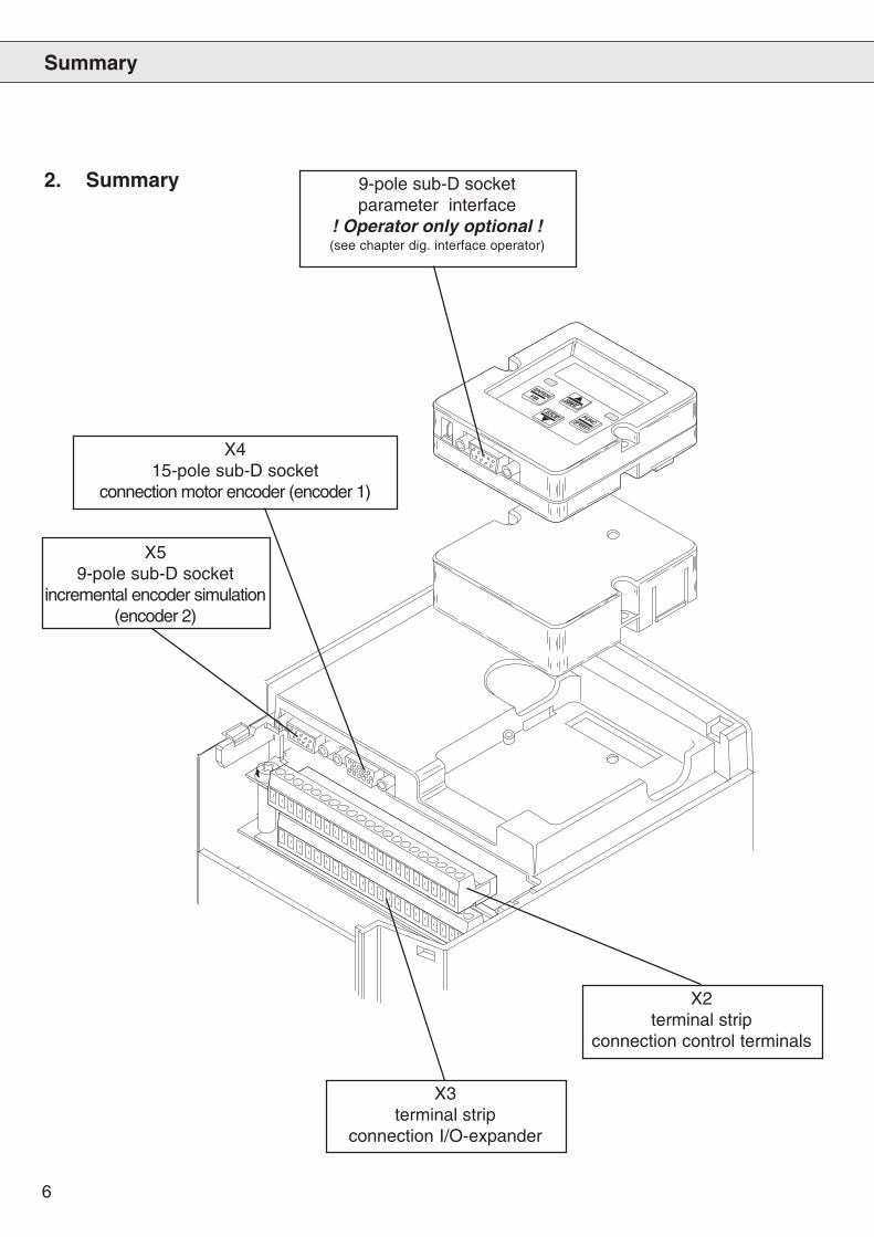
Summary
9-pole sub-D socketparameter interface
! Operator only optional !(see chapter dig. interface operator)
X415-pole sub-D socket
connection motor encoder (encoder 1)
X59-pole sub-D socket
incremental encoder simulation(encoder 2)
X2terminal strip
connection control terminals
X3terminal strip
connection I/O-expander
2. Summary
7
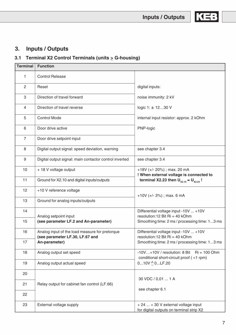
Terminal Function
1 Control Release
2 Reset digital inputs:
3 Direction of travel forward noise immunity: 2 kV
4 Direction of travel reverse logic 1: ± 12…30 V
5 Control Mode internal input resistor: approx. 2 kOhm
6 Door drive active PNP-logic
7 Door drive setpoint input
8 Digital output signal: speed deviation, warning see chapter 3.4
9 Digital output signal: main contactor control inverted see chapter 3.4
10 + 18 V voltage output +18V (+/- 20%) ; max. 20 mA! When external voltage is connected to
11 Ground for X2.10 and digital inputs/outputs terminal X2.23 then UX2.10 ≈≈≈≈≈ UX2.23 !
12 +10 V reference voltage+10V (+/- 3%) ; max. 6 mA
13 Ground for analog inputs/outputs
14 Differential voltage input -10V ... +10VAnalog setpoint input resolution:12 Bit Ri = 40 kOhm
15 (see parameter LF.2 and An-parameter) Smoothing time: 2 ms / processing time: 1...3 ms
16 Analog input of the load measure for pretorque Differential voltage input -10V ... +10V(see parameter LF.30, LF.67 and resolution:12 Bit Ri = 40 kOhm
17 An-parameter) Smoothing time: 2 ms / processing time: 1...3 ms
18 Analog output set speed -10V…+10V / resolution: 8 Bit Ri = 100 Ohmconditional short-circuit proof ( <1 rpm)
19 Analog output actual speed 0...10V ^ 0...LF.20
2030 VDC / 0,01 ... 1 A
21 Relay output for cabinet fan control (LF.66)see chapter 6.1
22
23 External voltage supply + 24 ... + 30 V external voltage inputfor digital outputs on terminal strip X2
3.1 Terminal X2 Control Terminals (units > G-housing)
Inputs / Outputs
3. Inputs / Outputs
8
3.2 Terminal X3 I/O-Expander (units > G-housing)
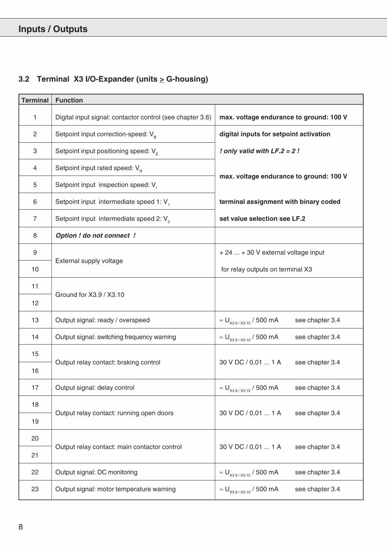
Terminal Function
1 Digital input signal: contactor control (see chapter 3.6) max. voltage endurance to ground: 100 V
2 Setpoint input correction-speed: VB
digital inputs for setpoint activation
3 Setpoint input positioning speed: VE
! only valid with LF.2 = 2 !
4 Setpoint input rated speed: VN
max. voltage endurance to ground: 100 V5 Setpoint input inspection speed: V
I
6 Setpoint input intermediate speed 1: V1
terminal assignment with binary coded
7 Setpoint input intermediate speed 2: V2
set value selection see LF.2
8 Option ! do not connect !
9 + 24 ... + 30 V external voltage inputExternal supply voltage
10 for relay outputs on terminal X3
11Ground for X3.9 / X3.10
12
13 Output signal: ready / overspeed ≈ UX3.9 / X3.10
/ 500 mA see chapter 3.4
14 Output signal: switching frequency warning ≈ UX3.9 / X3.10
/ 500 mA see chapter 3.4
15Output relay contact: braking control 30 V DC / 0,01 ... 1 A see chapter 3.4
16
17 Output signal: delay control ≈ UX3.9 / X3.10
/ 500 mA see chapter 3.4
18Output relay contact: running open doors 30 V DC / 0,01 ... 1 A see chapter 3.4
19
20Output relay contact: main contactor control 30 V DC / 0,01 ... 1 A see chapter 3.4
21
22 Output signal: DC monitoring ≈ UX3.9 / X3.10
/ 500 mA see chapter 3.4
23 Output signal: motor temperature warning ≈ UX3.9 / X3.10
/ 500 mA see chapter 3.4
Inputs / Outputs
9
Inputs / Outputs
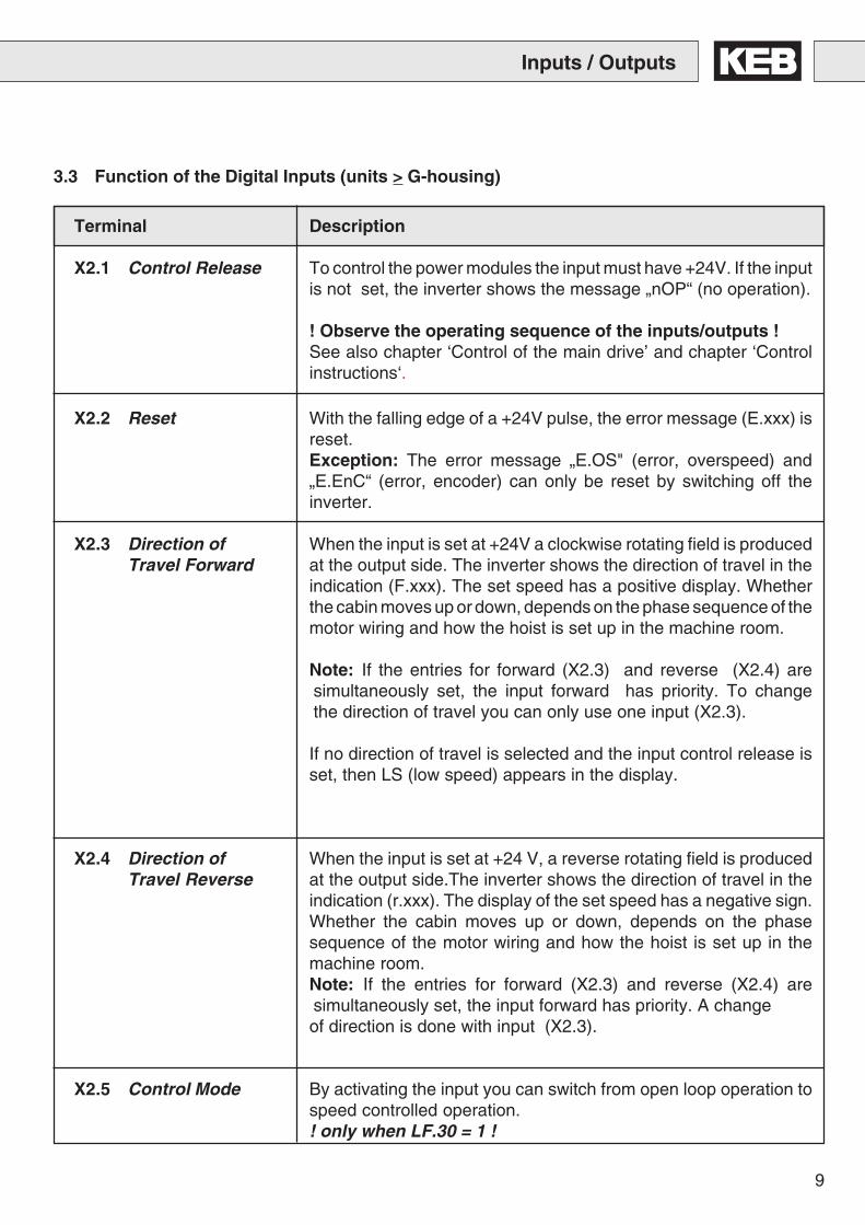
Terminal Description
X2.1 Control Release To control the power modules the input must have +24V. If the inputis not set, the inverter shows the message „nOP“ (no operation).
! Observe the operating sequence of the inputs/outputs !See also chapter ‘Control of the main drive’ and chapter ‘Controlinstructions‘.
X2.2 Reset With the falling edge of a +24V pulse, the error message (E.xxx) isreset.Exception: The error message „E.OS" (error, overspeed) and„E.EnC“ (error, encoder) can only be reset by switching off theinverter.
X2.3 Direction of When the input is set at +24V a clockwise rotating field is producedTravel Forward at the output side. The inverter shows the direction of travel in the
indication (F.xxx). The set speed has a positive display. Whetherthe cabin moves up or down, depends on the phase sequence of themotor wiring and how the hoist is set up in the machine room.
Note: If the entries for forward (X2.3) and reverse (X2.4) aresimultaneously set, the input forward has priority. To changethe direction of travel you can only use one input (X2.3).
If no direction of travel is selected and the input control release isset, then LS (low speed) appears in the display.
X2.4 Direction of When the input is set at +24 V, a reverse rotating field is producedTravel Reverse at the output side.The inverter shows the direction of travel in the
indication (r.xxx). The display of the set speed has a negative sign.Whether the cabin moves up or down, depends on the phasesequence of the motor wiring and how the hoist is set up in themachine room.Note: If the entries for forward (X2.3) and reverse (X2.4) aresimultaneously set, the input forward has priority. A changeof direction is done with input (X2.3).
X2.5 Control Mode By activating the input you can switch from open loop operation tospeed controlled operation.! only when LF.30 = 1 !
3.3 Function of the Digital Inputs (units > G-housing)
10
Terminal Description
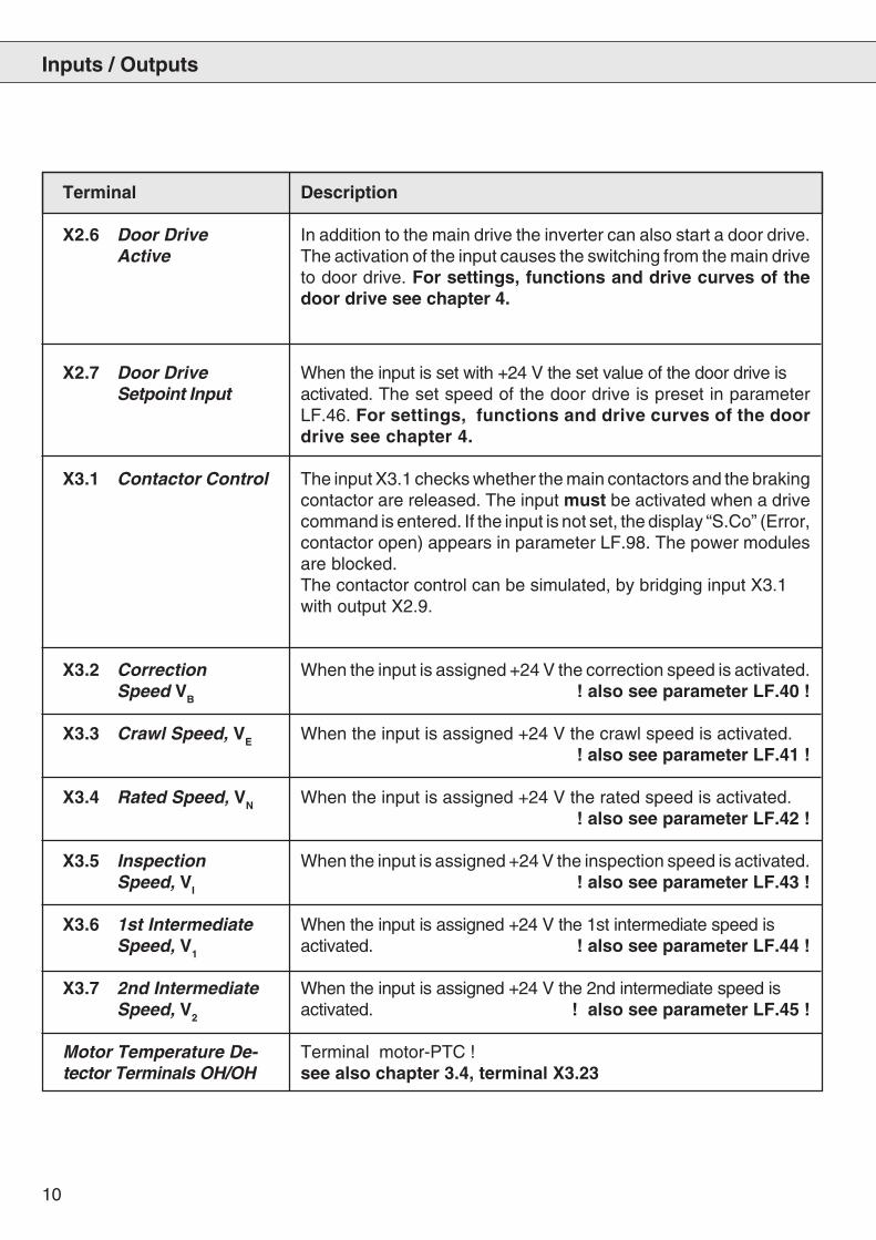
X2.6 Door Drive In addition to the main drive the inverter can also start a door drive.Active The activation of the input causes the switching from the main drive
to door drive. For settings, functions and drive curves of thedoor drive see chapter 4.
X2.7 Door Drive When the input is set with +24 V the set value of the door drive isSetpoint Input activated. The set speed of the door drive is preset in parameter
LF.46. For settings, functions and drive curves of the doordrive see chapter 4.
X3.1 Contactor Control The input X3.1 checks whether the main contactors and the brakingcontactor are released. The input must be activated when a drivecommand is entered. If the input is not set, the display “S.Co” (Error,contactor open) appears in parameter LF.98. The power modulesare blocked.The contactor control can be simulated, by bridging input X3.1with output X2.9.
X3.2 Correction When the input is assigned +24 V the correction speed is activated.Speed VB ! also see parameter LF.40 !
X3.3 Crawl Speed, VE When the input is assigned +24 V the crawl speed is activated. ! also see parameter LF.41 !
X3.4 Rated Speed, VN When the input is assigned +24 V the rated speed is activated.! also see parameter LF.42 !
X3.5 Inspection When the input is assigned +24 V the inspection speed is activated.Speed, VI ! also see parameter LF.43 !
X3.6 1st Intermediate When the input is assigned +24 V the 1st intermediate speed isSpeed, V1 activated. ! also see parameter LF.44 !
X3.7 2nd Intermediate When the input is assigned +24 V the 2nd intermediate speed isSpeed, V2 activated. ! also see parameter LF.45 !
Motor Temperature De- Terminal motor-PTC !tector Terminals OH/OH see also chapter 3.4, terminal X3.23
Inputs / Outputs
11
Terminal Description
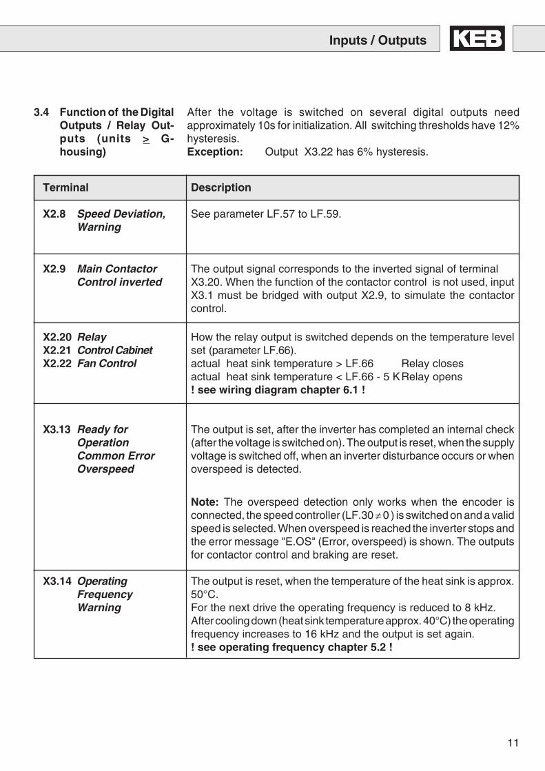
X2.8 Speed Deviation, See parameter LF.57 to LF.59.Warning
X2.9 Main Contactor The output signal corresponds to the inverted signal of terminalControl inverted X3.20. When the function of the contactor control is not used, input
X3.1 must be bridged with output X2.9, to simulate the contactorcontrol.
X2.20 Relay How the relay output is switched depends on the temperature levelX2.21 Control Cabinet set (parameter LF.66).X2.22 Fan Control actual heat sink temperature > LF.66 Relay closes
actual heat sink temperature < LF.66 - 5 KRelay opens! see wiring diagram chapter 6.1 !
X3.13 Ready for The output is set, after the inverter has completed an internal checkOperation (after the voltage is switched on). The output is reset, when the supplyCommon Error voltage is switched off, when an inverter disturbance occurs or whenOverspeed overspeed is detected.
Note: The overspeed detection only works when the encoder isconnected, the speed controller (LF.30 ≠ 0 ) is switched on and a validspeed is selected. When overspeed is reached the inverter stops andthe error message "E.OS" (Error, overspeed) is shown. The outputsfor contactor control and braking are reset.
X3.14 Operating The output is reset, when the temperature of the heat sink is approx.Frequency 50°C.Warning For the next drive the operating frequency is reduced to 8 kHz.
After cooling down (heat sink temperature approx. 40°C) the operatingfrequency increases to 16 kHz and the output is set again.! see operating frequency chapter 5.2 !
After the voltage is switched on several digital outputs needapproximately 10s for initialization. All switching thresholds have 12%hysteresis.Exception: Output X3.22 has 6% hysteresis.
Inputs / Outputs
3.4 Function of the DigitalOutputs / Relay Out-puts (units > G-housing)
12
Inputs / Outputs
Terminal Description
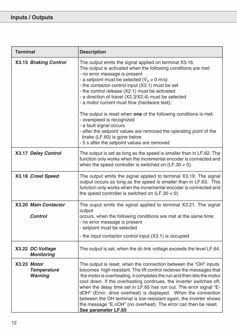
X3.15 Braking Control The output emits the signal applied on terminal X3.16.The output is activated when the following conditions are met:- no error message is present- a setpoint must be selected (VX ≠ 0 m/s)- the contactor control input (X3.1) must be set- the control release (X2.1) must be activated- a direction of travel (X2.3/X2.4) must be selected- a motor current must flow (hardware test);
The output is reset when one of the following conditions is met:- overspeed is recognized- a fault signal occurs- after the setpoint values are removed the operating point of the brake (LF.60) is gone below- 5 s after the setpoint values are removed
X3.17 Delay Control The output is set as long as the speed is smaller than in LF.62. Thefunction only works when the incremental encoder is connected andwhen the speed controller is switched on (LF.30 ≠ 0).
X3.18 Crawl Speed The output emits the signal applied to terminal X3.19. The signaloutput occurs as long as the speed is smaller than in LF.63. Thisfunction only works when the incremental encoder is connected andthe speed controller is switched on (LF.30 ≠ 0).
X3.20 Main Contactor The ouput emits the sginal applied to terminal X3.21. The signaloutput
Control occurs, when the following conditions are met at the same time:- no error message is present- setpoint must be selected
- the input contactor control input (X3.1) is occupied
X3.22 DC-Voltage The output is set, when the dc-link voltage exceeds the level LF.64.Monitoring
X3.23 Motor The output is reset, when the connection between the “OH” inputsTemperature becomes high-resistant. The lift control receives the messages thatWarning the motor is overheating, it completes the run and then lets the motor
cool down. If the overheating continues, the inverter switches off,when the delay time set in LF.65 has run out. The error signal “E-dOH” (Error, drive overheat) is displayed. When the connectionbetween the OH terminal is low-resistant again, the inverter showsthe message “E.nOH” (no overheat). The error can then be reset.See parameter LF.65

13
3.5 Terminal X2 Control Terminals (D- and E-housing)
Inputs / Outputs
Terminal Function
1 Control Release
2 Reset digital inputs:
3 Direction of travel forward noise immunity: 2 kV
4 Direction of travel reverse logic 1: ± 12…30 V
5 internal input resistor: approx. 2 kOhm
6 binary-coded setpoint setting (see parameter LF.02) PNP-logic
7
8 Digital output signal: braking control 14...30 V / max. 20mA (per output)
9 Digital output signal: main contactor control PNP-logic
10 + 18 V voltage output +18V (+/- 20%) ; max. 20 mA! When external voltage is connected to
11 Ground for X2.10 and digital inputs/outputs terminal X2.23 then UX2.10 ≈≈≈≈≈ UX2.23 !
12 +10 V reference voltage+10V (+/- 3%) ; max. 6 mA
13 Ground for analog inputs/outputs
14 Differential voltage input -10V ... +10VAnalog setpoint input resolution:12 Bit Ri = 40 kOhm
15 (see parameter LF.2 and An-parameter) Smoothing time: 2 ms / processing time: 1...3 ms
16 Analog input of the precontrol torque Differential voltage input -10V ... +10V(see parameter LF.30, LF.67 and resolution:12 Bit Ri = 40 kOhm
17 An-parameter) Smoothing time: 2 ms / processing time: 1...3 ms
18 Analog output set speed -10V…+10V / resolution: 8 Bit Ri = 100 Ohmconditional short-circuit proof ( <1 rpm)
19 Analog output actual speed 0...10V ^ 0...LF.20
2030 VDC / 0,01 ... 1 A
21 Relay: Ready / overspeedsee output signal description
22
23 External voltage supply + 24 ... + 30 V external voltage inputfor digital outputs
14
Terminal Description
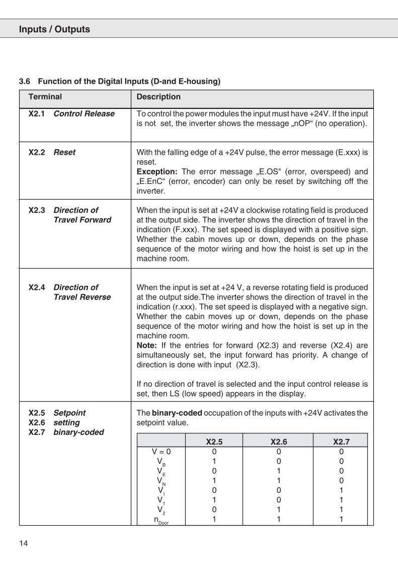
X2.1 Control Release To control the power modules the input must have +24V. If the inputis not set, the inverter shows the message „nOP“ (no operation).
X2.2 Reset With the falling edge of a +24V pulse, the error message (E.xxx) isreset.Exception: The error message „E.OS" (error, overspeed) and„E.EnC“ (error, encoder) can only be reset by switching off theinverter.
X2.3 Direction of When the input is set at +24V a clockwise rotating field is producedTravel Forward at the output side. The inverter shows the direction of travel in the
indication (F.xxx). The set speed is displayed with a positive sign.Whether the cabin moves up or down, depends on the phasesequence of the motor wiring and how the hoist is set up in themachine room.
X2.4 Direction of When the input is set at +24 V, a reverse rotating field is producedTravel Reverse at the output side.The inverter shows the direction of travel in the
indication (r.xxx). The set speed is displayed with a negative sign.Whether the cabin moves up or down, depends on the phasesequence of the motor wiring and how the hoist is set up in themachine room.Note: If the entries for forward (X2.3) and reverse (X2.4) aresimultaneously set, the input forward has priority. A change ofdirection is done with input (X2.3).
If no direction of travel is selected and the input control release isset, then LS (low speed) appears in the display.
X2.5 Setpoint The binary-coded occupation of the inputs with +24V activates theX2.6 setting setpoint value.X2.7 binary-coded
X2.5 X2.6 X2.7V = 0 0 0 0
VB
1 0 0V
E0 1 0
VN
1 1 0V
I0 0 1
V1
1 0 1V
20 1 1
nDoor
1 1 1
3.6 Function of the Digital Inputs (D-and E-housing)
Inputs / Outputs
15
Terminal Description
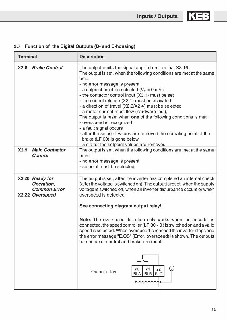
X2.8 Brake Control The output emits the signal applied on terminal X3.16.The output is set, when the following conditions are met at the sametime:- no error message is present- a setpoint must be selected (VX ≠ 0 m/s)- the contactor control input (X3.1) must be set- the control release (X2.1) must be activated- a direction of travel (X2.3/X2.4) must be selected- a motor current must flow (hardware test);The output is reset when one of the following conditions is met:- overspeed is recognized- a fault signal occurs- after the setpoint values are removed the operating point of the brake (LF.60) is gone below- 5 s after the setpoint values are removed
X2.9 Main Contactor The output is set, when the following conditions are met at the sameControl time:
- no error message is present- setpoint must be selected
X2.20 Ready for The output is set, after the inverter has completed an internal checkOperation, (after the voltage is switched on). The output is reset, when the supplyCommon Error voltage is switched off, when an inverter disturbance occurs or when
X2.22 Overspeed overspeed is detected.
See connecting diagram output relay!
Note: The overspeed detection only works when the encoder isconnected, the speed controller (LF.30 ≠ 0 ) is switched on and a validspeed is selected. When overspeed is reached the inverter stops andthe error message "E.OS" (Error, overspeed) is shown. The outputsfor contactor control and brake are reset.
3.7 Function of the Digital Outputs (D- and E-housing)
Inputs / Outputs
Output relay20
RLA21
RLB22
RLC
16
t
X3.3
X2.4
X2.3
X3.17
X3.20
X3.15
X3.18
X3.4
X3.1
X2.1
v
LF.62
LF.63
LF.60
LF.50
LF.51
LF.50
LF.42LF.61
LF.52
LF.53
LF.52 LF.54
LF.53
LF.54LF.41
123
45
6 7 8 9 10 11 12 13
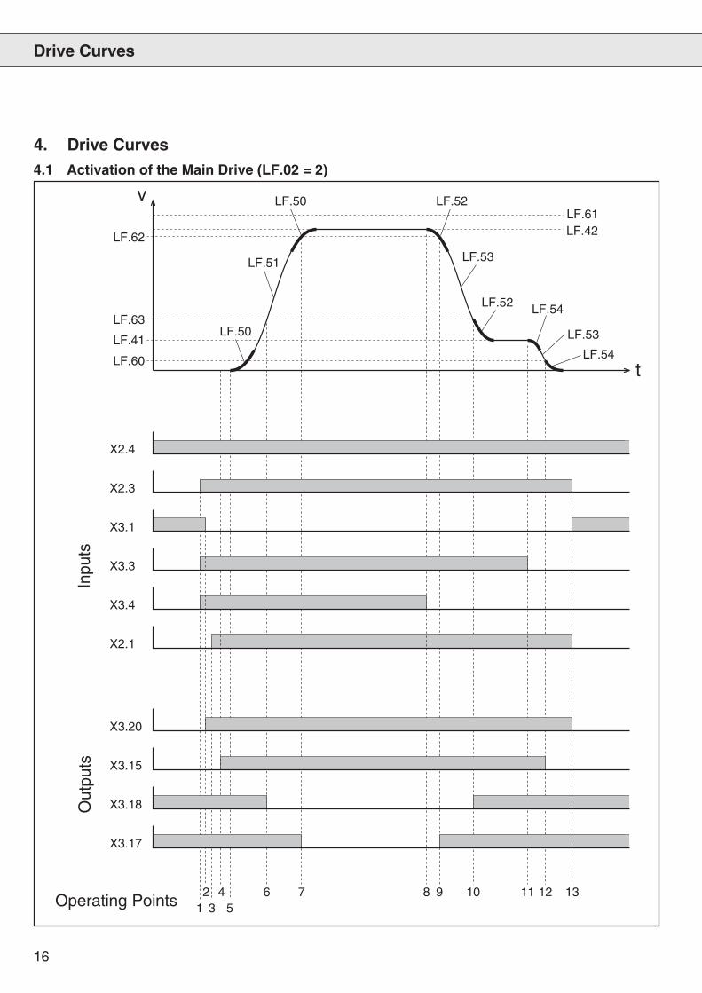
4.1 Activation of the Main Drive (LF.02 = 2)
Inpu
tsO
utpu
ts
Operating Points
Drive Curves
4. Drive Curves
17
1: Presetting of the setpoint for the drive speed and the selection ofthe direction of travel. The inverter checks whether input X3.1(contactor control) is set. If yes the output X3.20 (main contactorcontrol) is set. If X3.1 is not set, the display “S.Co“ is seen in LF.98and output X3.20 is not set.
2: If X3.20 is set, then X3.1 must be reset.
3: X2.1 (control release) is set with the precontrol contact of the maincontactor. After this is done the inverter provides the motor withcurrent, when the main contacts are connected (powerlessswitching).When the safety circuit is interrupted input X2.1 must be resetimmediately. (See chapter control instructions).
4: When the motor can receive a current (“hardware test”), the outputX3.15 (brake) is set. If there is not enough current flowing, you willsee the display “E.nC” in LF.98 and X3.15 is not set.
5: After X3.15 is set, the brake release time (LF.70) runs out; thenthe motor starts to turn.
6: When exceeding the monitoring of the running open door level(LF.63) the output X3.18 is reset.
7: When exceeding the monitoring of the deceleration check (LF.62)the output X3.17 is reset.
8: When the setpoint for the rated speed is removed (X3.4)deceleration starts.
9: When speed has under-run the level of the deceleration check(LF.62) the output X3.17 is set.
10: When speed has under-run the level of running open doors (LF.63)the output X3.18 is set.
11: When the limit switch is reached, the set value for the positioningspeed is set 0 and thus the drive keeps the cabin stopping untilthe brake is engaged,.
12: When the speed has under-run the level for the brake (LF.60), theoutput X3.15 is reset.
13: When X3.15 is reset, the modulation is switched off after the brakerelease time (LF.79) has run out. 0.3 s later output X3.20 is reset.
Drive Curves
WHAT HAPPENS WHEN? Description of the Operating Points of the Main Drive
18
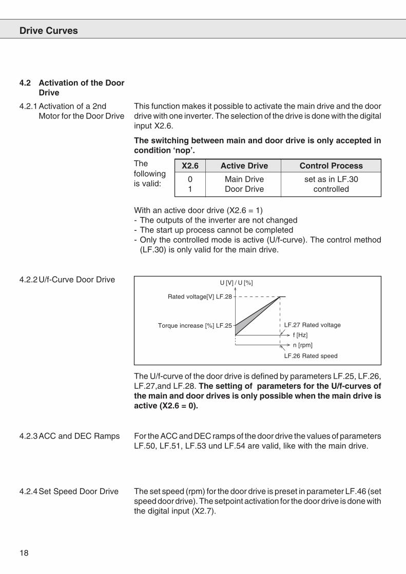
4.2.2U/f-Curve Door Drive
This function makes it possible to activate the main drive and the doordrive with one inverter. The selection of the drive is done with the digitalinput X2.6.
The switching between main and door drive is only accepted incondition ‘nop’.
X2.6 Active Drive Control Process
0 Main Drive set as in LF.301 Door Drive controlled
With an active door drive (X2.6 = 1)- The outputs of the inverter are not changed- The start up process cannot be completed- Only the controlled mode is active (U/f-curve). The control method
(LF.30) is only valid for the main drive.
4.2.1Activation of a 2ndMotor for the Door Drive
For the ACC and DEC ramps of the door drive the values of parametersLF.50, LF.51, LF.53 und LF.54 are valid, like with the main drive.
The set speed (rpm) for the door drive is preset in parameter LF.46 (setspeed door drive). The setpoint activation for the door drive is done withthe digital input (X2.7).
The U/f-curve of the door drive is defined by parameters LF.25, LF.26,LF.27,and LF.28. The setting of parameters for the U/f-curves ofthe main and door drives is only possible when the main drive isactive (X2.6 = 0).
Rated voltage[V] LF.28
LF.26 Rated speed
LF.27 Rated voltageTorque increase [%] LF.25
f [Hz]
n [rpm]
U [V] / U [%]
4.2.3ACC and DEC Ramps
4.2.4Set Speed Door Drive
Drive Curves
4.2 Activation of the DoorDrive
Thefollowingis valid:
19
t
X2.4
v
LF.46
1 2
LF.50
LF.51
LF.50
LF.54
LF.53
LF.54
X2.6
X2.3
X2.1
X2.7
Inpu
ts
Operating Points
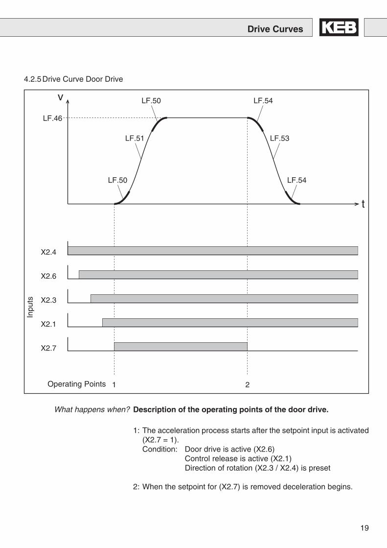
1: The acceleration process starts after the setpoint input is activated(X2.7 = 1).Condition: Door drive is active (X2.6)
Control release is active (X2.1)Direction of rotation (X2.3 / X2.4) is preset
2: When the setpoint for (X2.7) is removed deceleration begins.
Drive Curves
4.2.5Drive Curve Door Drive
What happens when? Description of the operating points of the door drive.
20
When the heat sink temperature reaches approximately 50°C, thesignal at output X3.14 (operating frequency warning) is reset. With aheat sink temperature of approx. 40°C the signal at the output is setagain.
Changes in the Operating Frequency
To protect KEB COMBIVERT F4-F Lift from overheating during 16kHzoperation and thus prevent the lift from being interrupted, the operatingfrequency can be reduced dependent on the heat sink temperature(only in condition ‘nop’). Inverters with temperature dependent operatingfrequencies are characterized in parameter In.0 with xx.F4.F1.-xxxx8kHz/16kHz. !see also parameter LF.38!
5.1 T e m p e r a t u r e -Dependent Changes inthe OperatingFrequency
5.2 Digital Output X3.14Operating FrequencyWarning
5. Changes in the Ope-rating Frequency
21
Connection
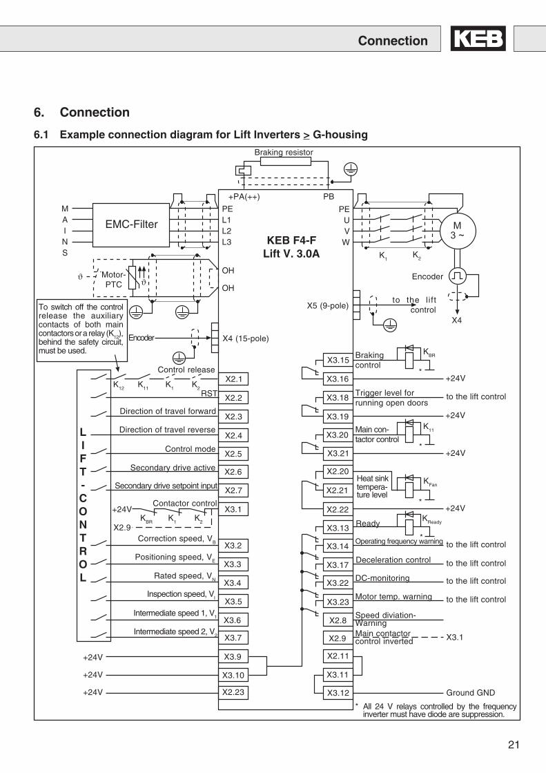
6.1 Example connection diagram for Lift Inverters > G-housing
����
X2.1
X2.2
X2.3
X2.4
X2.5
X2.6
X2.7
X3.1
X3.2
X3.3
X3.4
X3.5
X3.6
X3.7
X3.9
X3.10
X2.23
X3.15
X3.16
X3.18
X3.19
X3.20
X3.21
X2.20
X2.21
X2.22
X3.13
X3.14
X3.17
X3.22
X3.23
X2.8
X2.9
X2.11
X3.11
X3.12
Braking resistor
+PA(++) PB
PEUV
W
PEL1L2L3
EMC-Filter
MAINS K1
K2
Encoder
X4
to the liftcontrol
OH
OHϑ Motor-
PTC ϑ
Encoder X4 (15-pole)
X5 (9-pole)
KEB F4-FLift V. 3.0A
KBRBrakingcontrol
+24V
Trigger level forrunning open doors
to the lift control
Main con-tactor control
K11
+24V
+24V
KFan
+24VKReadyReady
Operating frequency warning to the lift control
Deceleration control
DC-monitoring
Motor temp. warning
Speed diviation-WarningMain contactorcontrol inverted
to the lift control
to the lift control
to the lift control
X3.1
Ground GND
*
*
*
*
Direction of travel forward
Direction of travel reverse
Control release
K12
LIFT-CONTROL
K11 K1 K2RST
Control mode
Secondary drive active
Secondary drive setpoint input
Contactor control
KBR K1 K2
+24V
X2.9Correction speed, VB
Positioning speed, VE
Rated speed, VN
Inspection speed, VI
Intermediate speed 1, V1
Intermediate speed 2, V2
+24V
+24V
+24V
To switch off the controlrelease the auxiliarycontacts of both maincontactors or a relay (K12),behind the safety circuit,must be used.
* All 24 V relays controlled by the frequencyinverter must have diode are suppression.
6. Connection
Heat sinktempera-ture level
22
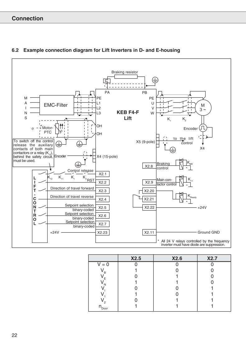
6.2 Example connection diagram for Lift Inverters in D- and E-housing
Connection
����
X2.1
X2.2
X2.3
X2.4
X2.5
X2.6
X2.7
X2.23
X2.8
X2.9
X2.20
X2.21
X2.22
X2.11
Braking resistor
PA PB
PEUVW
PEL1L2L3
EMC-Filter
MAINS K1
K2
Encoder
X4
to the liftcontrol
OH
OHϑ Motor-
PTC ϑ
Encoder X4 (15-pole)
X5 (9-pole)
KEB F4-FLift
KBRBrakingcontrol
Main con-tactor control
K11
+24V
Ground GND
*
*Direction of travel forward
Direction of travel reverse
Control release
K12LIFT-CONTROL
K11 K1 K2RST
Setpoint selectionbinary-coded
Setpoint selectionbinary-coded
Setpoint selectionbinary-coded
+24V
To switch off the controlrelease the auxiliarycontacts of both maincontactors or a relay (K12),behind the safety circuit,must be used.
KReady
*
* All 24 V relays controlled by the frequencyinverter must have diode are suppression.
X2.5 X2.6 X2.7V = 0 0 0 0
VB
1 0 0V
E0 1 0
VN
1 1 0V
I0 0 1
V1
1 0 1V
20 1 1
nDoor
1 1 1
23
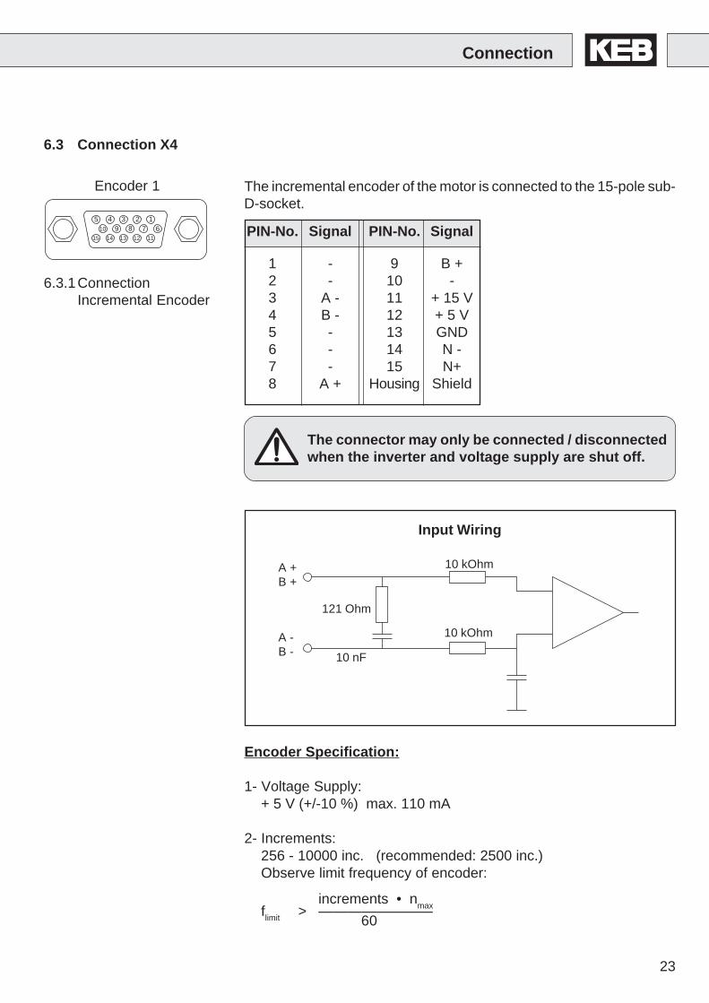
The incremental encoder of the motor is connected to the 15-pole sub-D-socket.
6.3 Connection X4
The connector may only be connected / disconnectedwhen the inverter and voltage supply are shut off.
Encoder Specification:
1- Voltage Supply:+ 5 V (+/-10 %) max. 110 mA
2- Increments:256 - 10000 inc. (recommended: 2500 inc.)Observe limit frequency of encoder:
increments • nmaxflimit > ————————
60
Input Wiring
A +B +
A -B -
121 Ohm
10 kOhm
10 kOhm
10 nF
Connection
6.3.1ConnectionIncremental Encoder
PIN-No. Signal PIN-No. Signal
1 - 9 B +2 - 10 -3 A - 11 + 15 V4 B - 12 + 5 V5 - 13 GND6 - 14 N -7 - 15 N+8 A + Housing Shield
Encoder 1
12345678910
1112131415
24
A+
B-
B+
A-
A+
B-
B+
A-
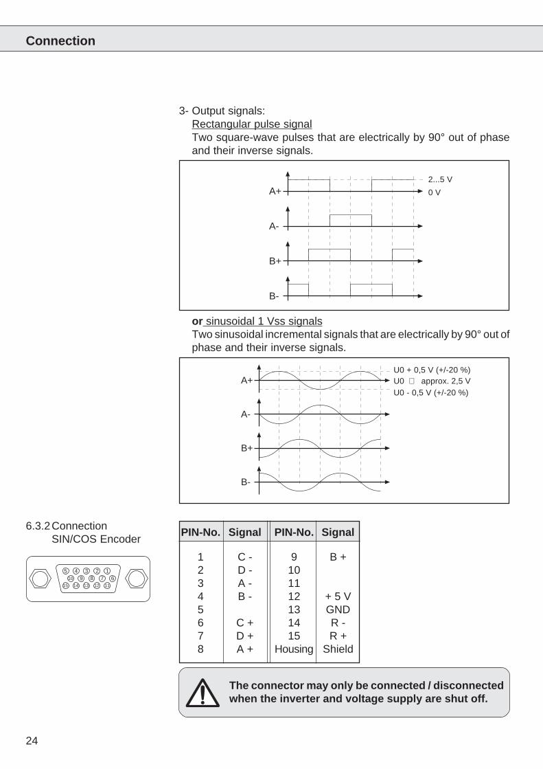
or sinusoidal 1 Vss signalsTwo sinusoidal incremental signals that are electrically by 90° out ofphase and their inverse signals.
3- Output signals:Rectangular pulse signalTwo square-wave pulses that are electrically by 90° out of phaseand their inverse signals.
2...5 V
0 V
U0 + 0,5 V (+/-20 %)
U0 - 0,5 V (+/-20 %)U0 ⇒ approx. 2,5 V
Connection
PIN-No. Signal PIN-No. Signal
1 C - 9 B +2 D - 103 A - 114 B - 12 + 5 V5 13 GND6 C + 14 R -7 D + 15 R +8 A + Housing Shield
The connector may only be connected / disconnectedwhen the inverter and voltage supply are shut off.
6.3.2ConnectionSIN/COS Encoder
12345678910
1112131415
25
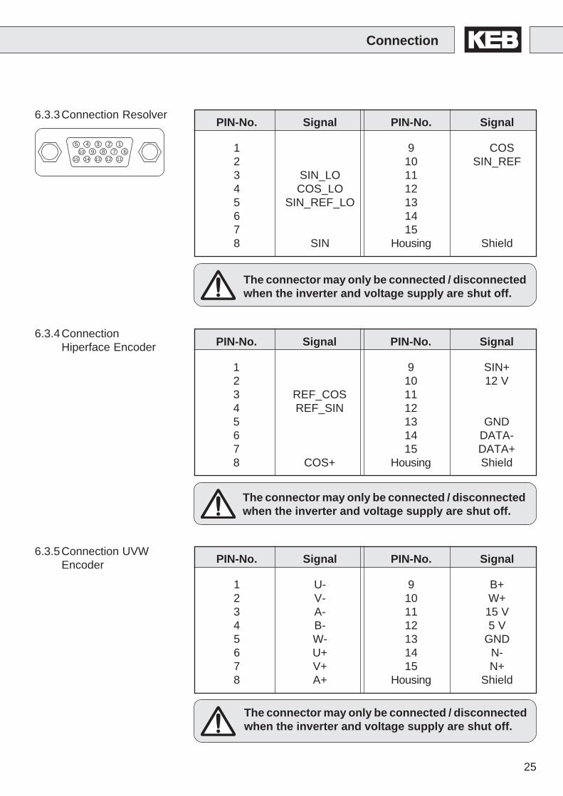
PIN-No. Signal PIN-No. Signal
1 9 COS2 10 SIN_REF3 SIN_LO 114 COS_LO 125 SIN_REF_LO 136 147 158 SIN Housing Shield
The connector may only be connected / disconnectedwhen the inverter and voltage supply are shut off.
6.3.3Connection Resolver
Connection
PIN-No. Signal PIN-No. Signal
1 9 SIN+2 10 12 V3 REF_COS 114 REF_SIN 125 13 GND6 14 DATA-7 15 DATA+8 COS+ Housing Shield
6.3.4ConnectionHiperface Encoder
PIN-No. Signal PIN-No. Signal
1 U- 9 B+2 V- 10 W+3 A- 11 15 V4 B- 12 5 V5 W- 13 GND6 U+ 14 N-7 V+ 15 N+8 A+ Housing Shield
6.3.5Connection UVWEncoder
The connector may only be connected / disconnectedwhen the inverter and voltage supply are shut off.
The connector may only be connected / disconnectedwhen the inverter and voltage supply are shut off.
12345678910
1112131415
26
12345
6789
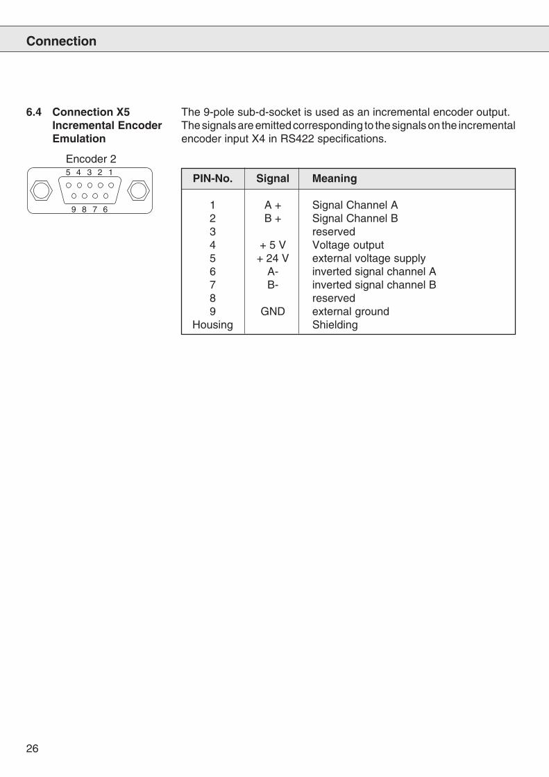
PIN-No. Signal Meaning
1 A + Signal Channel A2 B + Signal Channel B3 reserved4 + 5 V Voltage output5 + 24 V external voltage supply6 A- inverted signal channel A7 B- inverted signal channel B8 reserved9 GND external ground
Housing Shielding
6.4 Connection X5Incremental EncoderEmulation
The 9-pole sub-d-socket is used as an incremental encoder output.The signals are emitted corresponding to the signals on the incrementalencoder input X4 in RS422 specifications.
Connection
Encoder 2
27
12345
6789
START
STOP
FUNC.
SPEED
ENTER
F/R
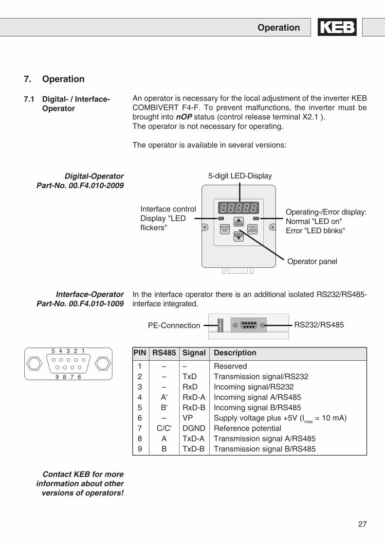
7.1 Digital- / Interface-Operator
Operator panel
Operating-/Error display:Normal "LED on"Error "LED blinks"
5-digit LED-Display
RS232/RS485PE-Connection
In the interface operator there is an additional isolated RS232/RS485-interface integrated.
Interface controlDisplay "LEDflickers"
Digital-OperatorPart-No. 00.F4.010-2009
Interface-OperatorPart-No. 00.F4.010-1009
Contact KEB for moreinformation about other
versions of operators!
Operation
7. Operation
An operator is necessary for the local adjustment of the inverter KEBCOMBIVERT F4-F. To prevent malfunctions, the inverter must bebrought into nOP status (control release terminal X2.1 ).The operator is not necessary for operating.
The operator is available in several versions:
PIN RS485 Signal Description
1 – – Reserved2 – TxD Transmission signal/RS2323 – RxD Incoming signal/RS2324 A' RxD-A Incoming signal A/RS4855 B' RxD-B Incoming signal B/RS4856 – VP Supply voltage plus +5V (I
max = 10 mA)
7 C/C' DGND Reference potential8 A TxD-A Transmission signal A/RS4859 B TxD-B Transmission signal B/RS485
28
ENTER
F/R START
STOP
FUNC.
SPEED
ENTER
F/R
START
STOP
FUNC.
SPEED
ENTER
F/R
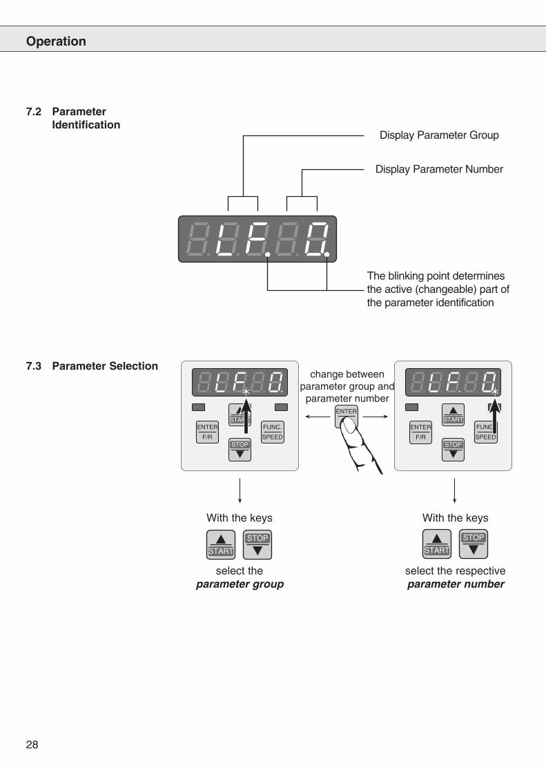
With the keys
select theparameter group
With the keys
select the respectiveparameter number
Operation
7.2 ParameterIdentification
Display Parameter Group
Display Parameter Number
The blinking point determinesthe active (changeable) part ofthe parameter identification
7.3 Parameter Selectionchange between
parameter group andparameter number
START
STOP
START
STOP
29
START
STOP
FUNC.
SPEED
START
STOP
FUNC.
SPEED
ENTER
F/R
START
STOP
FUNC.
SPEED
ENTER
F/R
Operation
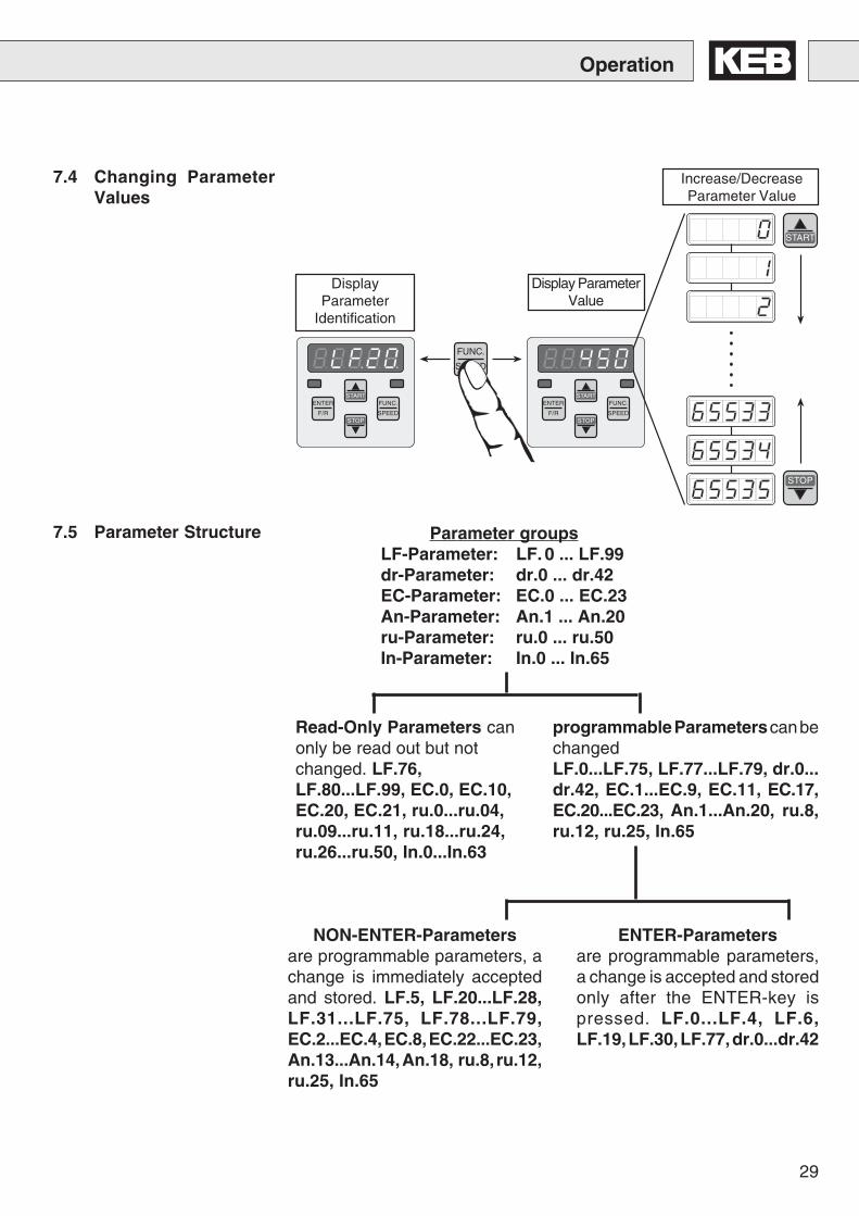
7.4 Changing ParameterValues
DisplayParameter
Identification
Display ParameterValue
Increase/DecreaseParameter Value
Read-Only Parameters canonly be read out but notchanged. LF.76,LF.80...LF.99, EC.0, EC.10,EC.20, EC.21, ru.0...ru.04,ru.09...ru.11, ru.18...ru.24,ru.26...ru.50, In.0...In.63
ENTER-Parametersare programmable parameters,a change is accepted and storedonly after the ENTER-key ispressed. LF.0...LF.4, LF.6,LF.19, LF.30, LF.77, dr.0...dr.42
Parameter groupsLF-Parameter: LF. 0 ... LF.99dr-Parameter: dr.0 ... dr.42EC-Parameter: EC.0 ... EC.23An-Parameter: An.1 ... An.20ru-Parameter: ru.0 ... ru.50In-Parameter: In.0 ... In.65
programmable Parameters can bechangedLF.0...LF.75, LF.77...LF.79, dr.0...dr.42, EC.1...EC.9, EC.11, EC.17,EC.20...EC.23, An.1...An.20, ru.8,ru.12, ru.25, In.65
NON-ENTER-Parametersare programmable parameters, achange is immediately acceptedand stored. LF.5, LF.20...LF.28,LF.31...LF.75, LF.78...LF.79,EC.2...EC.4, EC.8, EC.22...EC.23,An.13...An.14, An.18, ru.8, ru.12,ru.25, In.65
7.5 Parameter Structure
30
START
STOP
ENTER
F/R
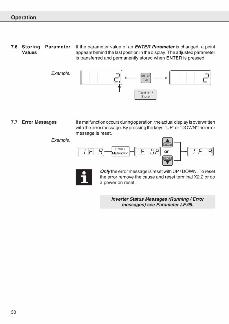
7.6 Storing ParameterValues
If the parameter value of an ENTER Parameter is changed, a pointappears behind the last position in the display. The adjusted parameteris transferred and permanently stored when ENTER is pressed.
7.7 Error Messages
Only the error message is reset with UP / DOWN. To resetthe error remove the cause and reset terminal X2.2 or doa power on reset.
Inverter Status Messages (Running / Errormessages) see Parameter LF.99.
Error /Malfunction or
If a malfunction occurs during operation, the actual display is overwrittenwith the error message. By pressing the keys "UP" or "DOWN" the errormessage is reset.
Operation
Transfer /Store
Example:
Example:
31
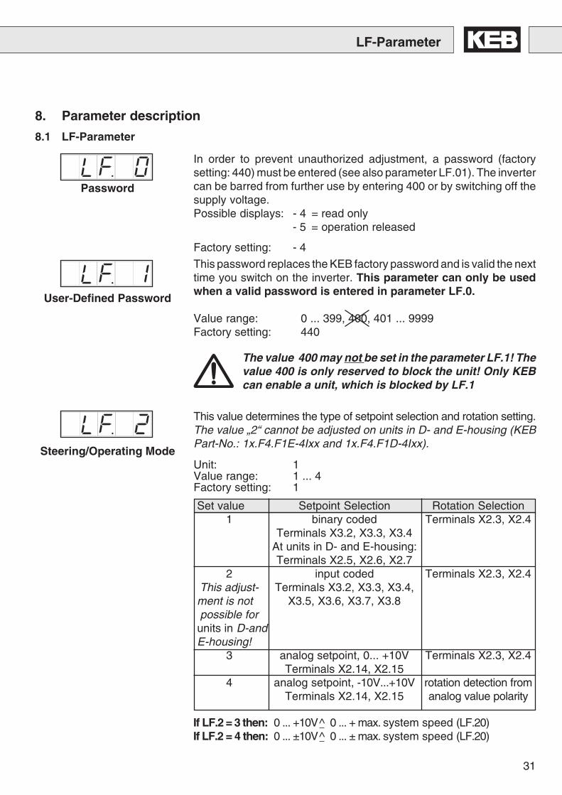
Set value Setpoint Selection Rotation Selection1 binary coded Terminals X2.3, X2.4
Terminals X3.2, X3.3, X3.4At units in D- and E-housing:Terminals X2.5, X2.6, X2.7
2 input coded Terminals X2.3, X2.4This adjust- Terminals X3.2, X3.3, X3.4,ment is not X3.5, X3.6, X3.7, X3.8possible forunits in D-andE-housing!
3 analog setpoint, 0... +10V Terminals X2.3, X2.4Terminals X2.14, X2.15
4 analog setpoint, -10V...+10V rotation detection fromTerminals X2.14, X2.15 analog value polarity
LF-Parameter
In order to prevent unauthorized adjustment, a password (factorysetting: 440) must be entered (see also parameter LF.01). The invertercan be barred from further use by entering 400 or by switching off thesupply voltage.Possible displays: - 4 = read only
- 5 = operation released
Factory setting: - 4
Password
This value determines the type of setpoint selection and rotation setting.The value „2“ cannot be adjusted on units in D- and E-housing (KEBPart-No.: 1x.F4.F1E-4Ixx and 1x.F4.F1D-4Ixx).
Unit: 1Value range: 1 ... 4Factory setting: 1
User-Defined Password
8.1 LF-Parameter
Steering/Operating Mode
The value 400 may not be set in the parameter LF.1! Thevalue 400 is only reserved to block the unit! Only KEBcan enable a unit, which is blocked by LF.1
This password replaces the KEB factory password and is valid the nexttime you switch on the inverter. This parameter can only be usedwhen a valid password is entered in parameter LF.0.
Value range: 0 ... 399, 400, 401 ... 9999Factory setting: 440
If LF.2 = 3 then: 0 ... +10V^ 0 ... + max. system speed (LF.20)If LF.2 = 4 then: 0 ... ±10V^ 0 ... ± max. system speed (LF.20)
8. Parameter description
32
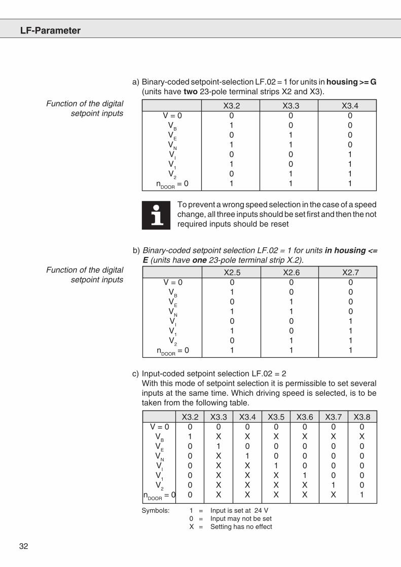
X3.2 X3.3 X3.4V = 0 0 0 0
VB 1 0 0VE 0 1 0VN 1 1 0VI 0 0 1V1 1 0 1V2 0 1 1
nDOOR = 0 1 1 1
Function of the digitalsetpoint inputs
c) Input-coded setpoint selection LF.02 = 2With this mode of setpoint selection it is permissible to set severalinputs at the same time. Which driving speed is selected, is to betaken from the following table.
LF-Parameter
X3.2 X3.3 X3.4 X3.5 X3.6 X3.7 X3.8V = 0 0 0 0 0 0 0 0
VB
1 X X X X X XV
E0 1 0 0 0 0 0
VN
0 X 1 0 0 0 0V
I0 X X 1 0 0 0
V1
0 X X X 1 0 0V
20 X X X X 1 0
nDOOR
= 0 0 X X X X X 1
To prevent a wrong speed selection in the case of a speedchange, all three inputs should be set first and then the notrequired inputs should be reset
a) Binary-coded setpoint-selection LF.02 = 1 for units in housing >= G(units have two 23-pole terminal strips X2 and X3).
X2.5 X2.6 X2.7V = 0 0 0 0
VB 1 0 0VE 0 1 0VN 1 1 0VI 0 0 1V1 1 0 1V2 0 1 1
nDOOR = 0 1 1 1
b) Binary-coded setpoint selection LF.02 = 1 for units in housing <=E (units have one 23-pole terminal strip X.2).
Symbols: 1 = Input is set at 24 V0 = Input may not be setX = Setting has no effect
Function of the digitalsetpoint inputs
33
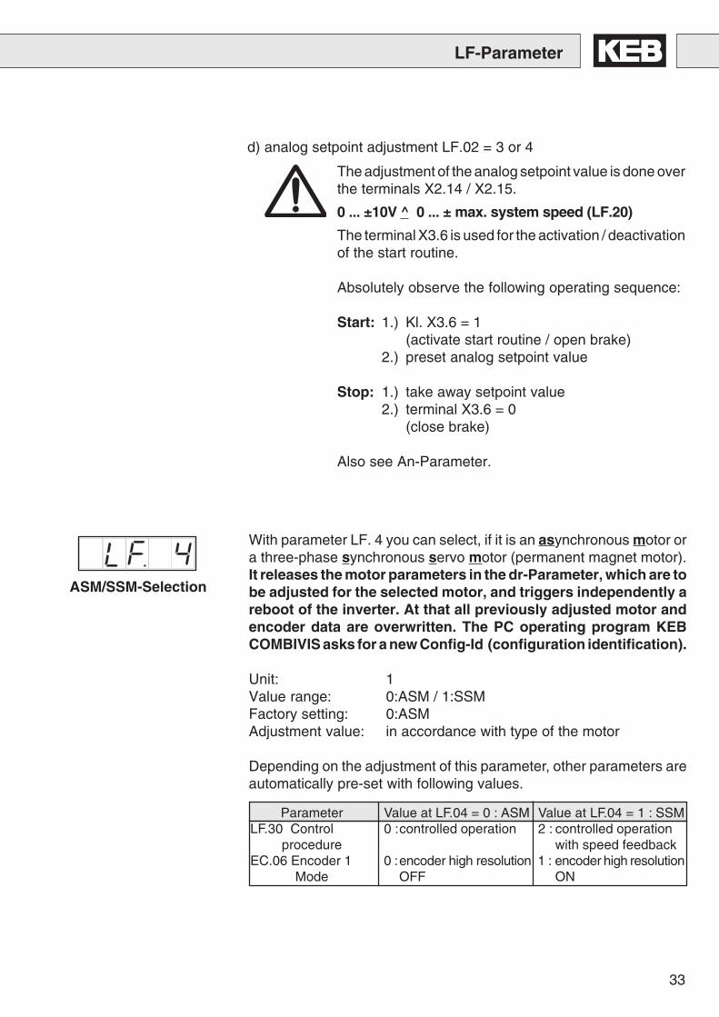
d) analog setpoint adjustment LF.02 = 3 or 4
LF-Parameter
The adjustment of the analog setpoint value is done overthe terminals X2.14 / X2.15.
0 ... ±10V ^ 0 ... ± max. system speed (LF.20)
The terminal X3.6 is used for the activation / deactivationof the start routine.
Absolutely observe the following operating sequence:
Start: 1.) Kl. X3.6 = 1(activate start routine / open brake)
2.) preset analog setpoint value
Stop: 1.) take away setpoint value2.) terminal X3.6 = 0
(close brake)
Also see An-Parameter.
ASM/SSM-Selection
With parameter LF. 4 you can select, if it is an asynchronous motor ora three-phase synchronous servo motor (permanent magnet motor).It releases the motor parameters in the dr-Parameter, which are tobe adjusted for the selected motor, and triggers independently areboot of the inverter. At that all previously adjusted motor andencoder data are overwritten. The PC operating program KEBCOMBIVIS asks for a new Config-Id (configuration identification).
Unit: 1Value range: 0:ASM / 1:SSMFactory setting: 0:ASMAdjustment value: in accordance with type of the motor
Depending on the adjustment of this parameter, other parameters areautomatically pre-set with following values.
Parameter Value at LF.04 = 0 : ASM Value at LF.04 = 1 : SSMLF.30 Control 0 :controlled operation 2 : controlled operation
procedure with speed feedbackEC.06 Encoder 1 0 :encoder high resolution 1 : encoder high resolution
Mode OFF ON
34
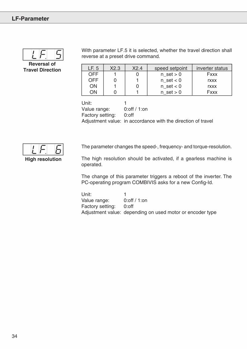
High resolution
The parameter changes the speed-, frequency- and torque-resolution.
The high resolution should be activated, if a gearless machine isoperated.
The change of this parameter triggers a reboot of the inverter. ThePC-operating program COMBIVIS asks for a new Config-Id.
Unit: 1Value range: 0:off / 1:onFactory setting: 0:offAdjustment value: depending on used motor or encoder type
With parameter LF.5 it is selected, whether the travel direction shallreverse at a preset drive command.
LF. 5 X2.3 X2.4 speed setpoint inverter statusOFF 1 0 n_set > 0 FxxxOFF 0 1 n_set < 0 rxxxON 1 0 n_set < 0 rxxxON 0 1 n_set > 0 Fxxx
Unit: 1Value range: 0:off / 1:onFactory setting: 0:offAdjustment value: in accordance with the direction of travel
LF-Parameter
Reversal ofTravel Direction
35
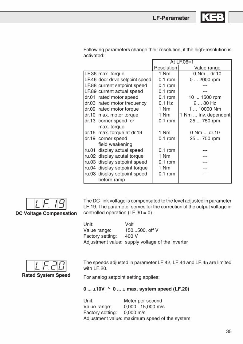
At LF.06=1Resolution Value range
LF.36 max. torque 1 Nm 0 Nm... dr.10LF.46 door drive setpoint speed 0.1 rpm 0 ... 2000 rpmLF.88 current setpoint speed 0.1 rpm ---LF.89 current actual speed 0.1 rpm ---dr.01 rated motor speed 0.1 rpm 10 ... 1500 rpmdr.03 rated motor frequency 0.1 Hz 2 ... 80 Hzdr.09 rated motor torque 1 Nm 1 ... 10000 Nmdr.10 max. motor torque 1 Nm 1 Nm ... Inv. dependentdr.13 corner speed for 0.1 rpm 25 ... 750 rpm
max. torquedr.16 max. torque at dr.19 1 Nm 0 Nm ... dr.10dr.19 corner speed 0.1 rpm 25 ... 750 rpm
field weakeningru.01 display actual speed 0.1 rpm ---ru.02 display acutal torque 1 Nm ---ru.03 display setpoint speed 0.1 rpm ---ru.04 display setpoint torque 1 Nm ---ru.03 display setpoint speed 0.1 rpm ---
before ramp
Following parameters change their resolution, if the high-resolution isactivated:
LF-Parameter
DC Voltage Compensation
The DC-link voltage is compensated to the level adjusted in parameterLF.19. The parameter serves for the correction of the output voltage incontrolled operation (LF.30 = 0).
Unit: VoltValue range: 150...500, off VFactory setting: 400 VAdjustment value: supply voltage of the inverter
Rated System Speed
The speeds adjusted in parameter LF.42, LF.44 and LF.45 are limitedwith LF.20.
For analog setpoint setting applies:
0 ... ±10V ^ 0 ... ± max. system speed (LF.20)
Unit: Meter per secondValue range: 0,000...15,000 m/sFactory setting: 0,000 m/sAdjustment value: maximum speed of the system
36
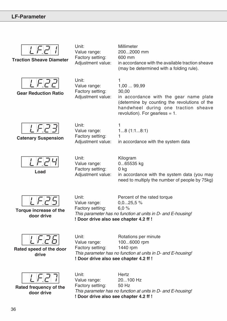
Unit: 1Value range: 1,00 ... 99,99Factory setting: 30,00Adjustment value: in accordance with the gear name plate
(determine by counting the revolutions of thehandwheel during one traction sheaverevolution). For gearless = 1.
Traction Sheave Diameter
Unit: MillimeterValue range: 200...2000 mmFactory setting: 600 mmAdjustment value: in accordance with the available traction sheave
(may be determined with a folding rule).
Gear Reduction Ratio
Unit: 1Value range: 1...8 (1:1...8:1)Factory setting: 1Adjustment value: in accordance with the system data
Catenary Suspension
LF-Parameter
Unit: Percent of the rated torqueValue range: 0,0...25,5 %Factory setting: 6,0 %This parameter has no function at units in D- and E-housing!! Door drive also see chapter 4.2 ff !
Torque increase of thedoor drive
Unit: Rotations per minuteValue range: 100...6000 rpmFactory setting: 1440 rpmThis parameter has no function at units in D- and E-housing!! Door drive also see chapter 4.2 ff !
Rated speed of the doordrive
Unit: HertzValue range: 20...100 HzFactory setting: 50 HzThis parameter has no function at units in D- and E-housing!! Door drive also see chapter 4.2 ff !
Rated frequency of thedoor drive
Load
Unit: KilogramValue range: 0...65535 kgFactory setting: 0 kgAdjustment value: in accordance with the system data (you may
need to multiply the number of people by 75kg)
37
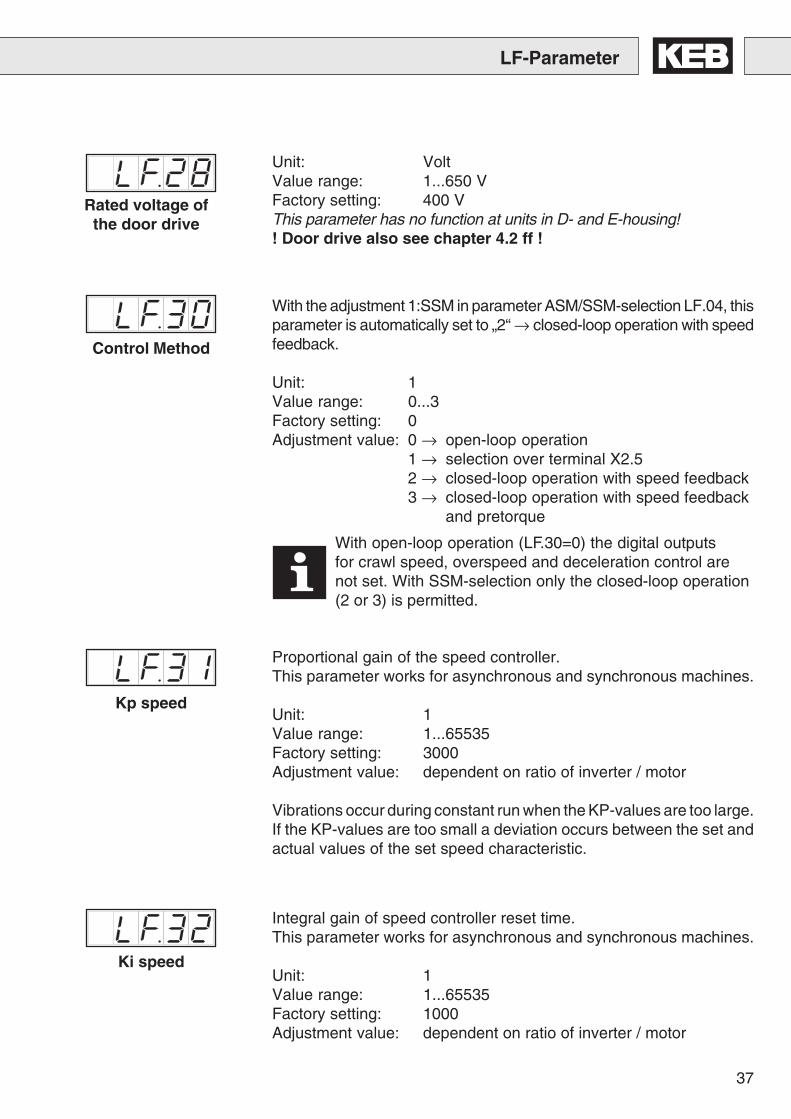
With the adjustment 1:SSM in parameter ASM/SSM-selection LF.04, thisparameter is automatically set to „2“ → closed-loop operation with speedfeedback.
Unit: 1Value range: 0...3Factory setting: 0Adjustment value: 0 → open-loop operation
1 → selection over terminal X2.52 → closed-loop operation with speed feedback3 → closed-loop operation with speed feedback
and pretorque
LF-Parameter
Unit: VoltValue range: 1...650 VFactory setting: 400 VThis parameter has no function at units in D- and E-housing!! Door drive also see chapter 4.2 ff !
Control Method
Ki speed
Proportional gain of the speed controller.This parameter works for asynchronous and synchronous machines.
Unit: 1Value range: 1...65535Factory setting: 3000Adjustment value: dependent on ratio of inverter / motor
Vibrations occur during constant run when the KP-values are too large.If the KP-values are too small a deviation occurs between the set andactual values of the set speed characteristic.
Integral gain of speed controller reset time.This parameter works for asynchronous and synchronous machines.
Unit: 1Value range: 1...65535Factory setting: 1000Adjustment value: dependent on ratio of inverter / motor
Kp speed
With open-loop operation (LF.30=0) the digital outputsfor crawl speed, overspeed and deceleration control arenot set. With SSM-selection only the closed-loop operation(2 or 3) is permitted.
Rated voltage ofthe door drive
38
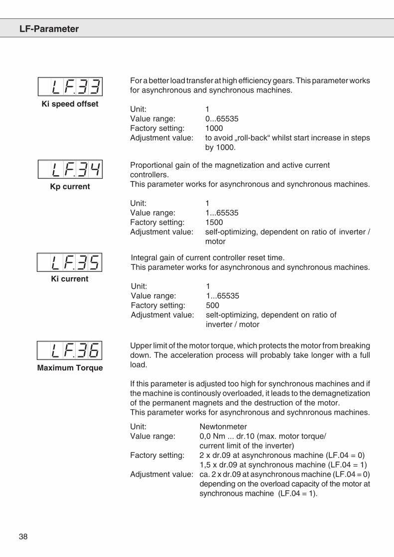
For a better load transfer at high efficiency gears. This parameter worksfor asynchronous and synchronous machines.
Unit: 1Value range: 0...65535Factory setting: 1000Adjustment value: to avoid „roll-back“ whilst start increase in steps
by 1000.
Ki speed offset
Proportional gain of the magnetization and active currentcontrollers.This parameter works for asynchronous and synchronous machines.
Unit: 1Value range: 1...65535Factory setting: 1500Adjustment value: self-optimizing, dependent on ratio of inverter /
motor
Kp current
Ki current
Integral gain of current controller reset time.This parameter works for asynchronous and synchronous machines.
Unit: 1Value range: 1...65535Factory setting: 500Adjustment value: selt-optimizing, dependent on ratio of
inverter / motor
LF-Parameter
Maximum Torque
Upper limit of the motor torque, which protects the motor from breakingdown. The acceleration process will probably take longer with a fullload.
If this parameter is adjusted too high for synchronous machines and ifthe machine is continously overloaded, it leads to the demagnetizationof the permanent magnets and the destruction of the motor.This parameter works for asynchronous and sychnronous machines.
Unit: NewtonmeterValue range: 0,0 Nm ... dr.10 (max. motor torque/
current limit of the inverter)Factory setting: 2 x dr.09 at asynchronous machine (LF.04 = 0)
1,5 x dr.09 at synchronous machine (LF.04 = 1)Adjustment value: ca. 2 x dr.09 at asynchronous machine (LF.04 = 0)
depending on the overload capacity of the motor atsynchronous machine (LF.04 = 1).
39
LF-Parameter
Set Value VB,Correction Speed
Operating FrequencyChange
Set Value VE,Crawl Speed
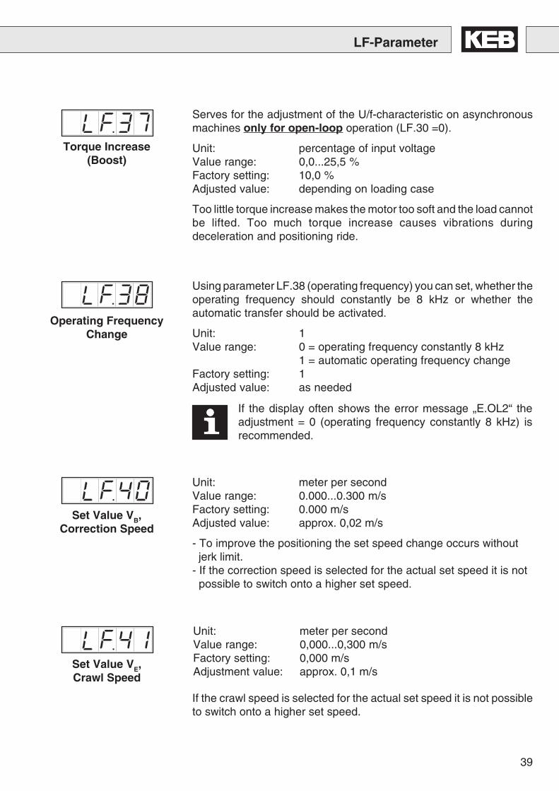
Serves for the adjustment of the U/f-characteristic on asynchronousmachines only for open-loop operation (LF.30 =0).
Unit: percentage of input voltageValue range: 0,0...25,5 %Factory setting: 10,0 %Adjusted value: depending on loading case
Too little torque increase makes the motor too soft and the load cannotbe lifted. Too much torque increase causes vibrations duringdeceleration and positioning ride.
Torque Increase(Boost)
Using parameter LF.38 (operating frequency) you can set, whether theoperating frequency should constantly be 8 kHz or whether theautomatic transfer should be activated.
Unit: 1Value range: 0 = operating frequency constantly 8 kHz
1 = automatic operating frequency changeFactory setting: 1Adjusted value: as needed
If the display often shows the error message „E.OL2“ theadjustment = 0 (operating frequency constantly 8 kHz) isrecommended.
Unit: meter per secondValue range: 0.000...0.300 m/sFactory setting: 0.000 m/sAdjusted value: approx. 0,02 m/s
- To improve the positioning the set speed change occurs without jerk limit.- If the correction speed is selected for the actual set speed it is not possible to switch onto a higher set speed.
Unit: meter per secondValue range: 0,000...0,300 m/sFactory setting: 0,000 m/sAdjustment value: approx. 0,1 m/s
If the crawl speed is selected for the actual set speed it is not possibleto switch onto a higher set speed.
40
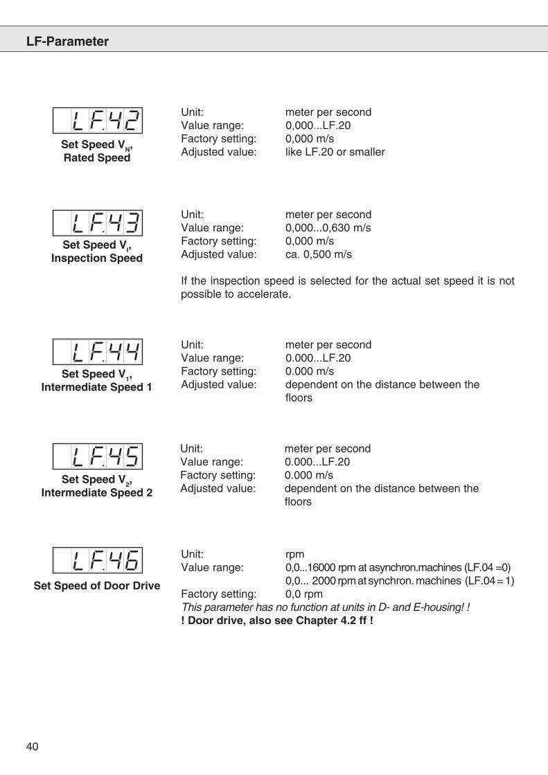
Unit: rpmValue range: 0,0...16000 rpm at asynchron.machines (LF.04 =0)
0,0... 2000 rpm at synchron. machines (LF.04 = 1)Factory setting: 0,0 rpmThis parameter has no function at units in D- and E-housing! !! Door drive, also see Chapter 4.2 ff !
Set Speed of Door Drive
Set Speed V1,Intermediate Speed 1
Set Speed V2,Intermediate Speed 2
LF-Parameter
Unit: meter per secondValue range: 0,000...0,630 m/sFactory setting: 0,000 m/sAdjusted value: ca. 0,500 m/s
If the inspection speed is selected for the actual set speed it is notpossible to accelerate.
Set Speed VI,Inspection Speed
Set Speed VN,Rated Speed
Unit: meter per secondValue range: 0,000...LF.20Factory setting: 0,000 m/sAdjusted value: like LF.20 or smaller
Unit: meter per secondValue range: 0.000...LF.20Factory setting: 0.000 m/sAdjusted value: dependent on the distance between the
floors
Unit: meter per secondValue range: 0.000...LF.20Factory setting: 0.000 m/sAdjusted value: dependent on the distance between the
floors
41
LF.50
LF.50
LF.51
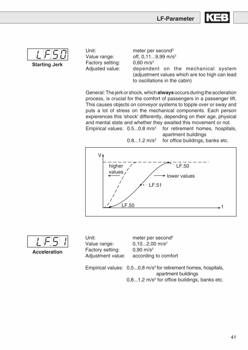
Acceleration
Starting Jerk
highervalues
lower values
V
t
LF-Parameter
Unit: meter per second3
Value range: off, 0,11...9,99 m/s3
Factory setting: 0,60 m/s3
Adjusted value: dependent on the mechanical system(adjustment values which are too high can leadto oscillations in the cabin)
General: The jerk or shock, which always occurs during the acclerationprocess, is crucial for the comfort of passengers in a passenger lift.This causes objects on conveyor systems to topple over or sway andputs a lot of stress on the mechanical components. Each personexpierences this 'shock' differently, depending on their age, physicaland mental state and whether they awaited this movement or not.Empirical values: 0.5...0.8 m/s3 for retirement homes, hospitals,
apartment buildings0.8...1.2 m/s3 for office buildings, banks etc.
Unit: meter per second2
Value range: 0,10...2,00 m/s2
Factory setting: 0,90 m/s2
Adjustment value: according to comfort
Empirical values: 0,5...0,8 m/s2 for retirement homes, hospitals,apartment buildings
0,8...1,2 m/s2 for office buildings, banks etc.
42
LF-Parameter
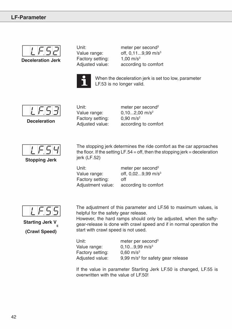
Deceleration
Stopping Jerk
Unit: meter per second2
Value range: 0,10...2,00 m/s2
Factory setting: 0,90 m/s2
Adjusted value: according to comfort
Deceleration Jerk
Starting Jerk VE
(Crawl Speed)
The adjustment of this parameter and LF.56 to maximum values, ishelpful for the safety gear release.However, the hard ramps should only be adjusted, when the safty-gear-release is done with crawl speed and if in normal operation thestart with crawl speed is not used.
Unit: meter per second3
Value range: 0,10...9,99 m/s3
Factory setting: 0,60 m/s3
Adjusted value: 9,99 m/s3 for safety gear release
If the value in parameter Starting Jerk LF.50 is changed, LF.55 isoverwritten with the value of LF.50!
Unit: meter per second3
Value range: off, 0,11...9,99 m/s3
Factory setting: 1,00 m/s3
Adjusted value: according to comfort
When the deceleration jerk is set too low, parameterLF.53 is no longer valid.
The stopping jerk determines the ride comfort as the car approachesthe floor. If the setting LF.54 = off, then the stopping jerk = decelerationjerk (LF.52)
Unit: meter per second3
Value range: off, 0,02...9,99 m/s3
Factory setting: offAdjustment value: according to comfort
43
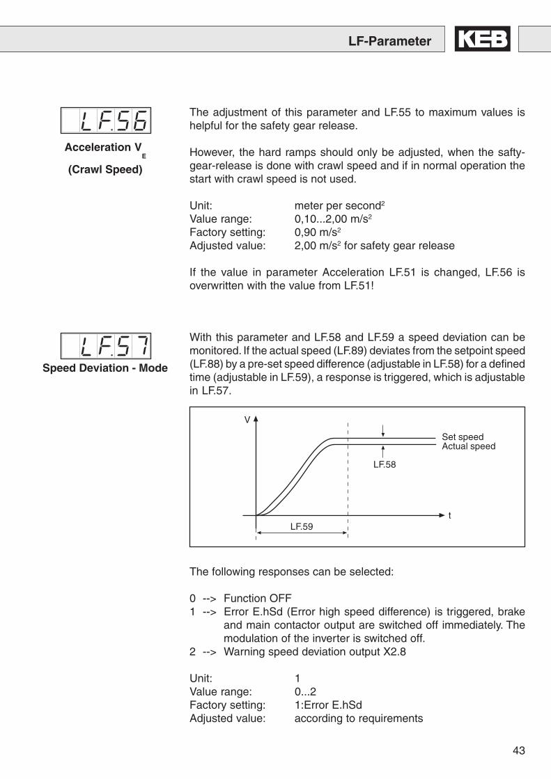
Speed Deviation - Mode
With this parameter and LF.58 and LF.59 a speed deviation can bemonitored. If the actual speed (LF.89) deviates from the setpoint speed(LF.88) by a pre-set speed difference (adjustable in LF.58) for a definedtime (adjustable in LF.59), a response is triggered, which is adjustablein LF.57.
The following responses can be selected:
0 --> Function OFF1 --> Error E.hSd (Error high speed difference) is triggered, brake
and main contactor output are switched off immediately. Themodulation of the inverter is switched off.
2 --> Warning speed deviation output X2.8
Unit: 1Value range: 0...2Factory setting: 1:Error E.hSdAdjusted value: according to requirements
V
LF.59
LF.58
t
Set speedActual speed
LF-Parameter
Acceleration VE
(Crawl Speed)
The adjustment of this parameter and LF.55 to maximum values ishelpful for the safety gear release.
However, the hard ramps should only be adjusted, when the safty-gear-release is done with crawl speed and if in normal operation thestart with crawl speed is not used.
Unit: meter per second2
Value range: 0,10...2,00 m/s2
Factory setting: 0,90 m/s2
Adjusted value: 2,00 m/s2 for safety gear release
If the value in parameter Acceleration LF.51 is changed, LF.56 isoverwritten with the value from LF.51!
44
Speed Deviation - Level
Speed Deviation - ReleaseTime
Percentage value referring to the selected speed at which a response,selected in LF.57, is released.
Unit: percentValue range: 0...30 % with reference to the selected speedFactory setting: 10 % of the selected speedAdjusted value: as needed
Adjustable time for which a proportional speed deviation LF.58 isallowed before a response, selected in LF.57, is released.
Unit: secondsValue range: 0,000...10,000 sFactory setting: 3,000 sAdjusted value: as needed
Monitoring Overspeed
If the current speed becomes larger than the value adjusted here, theinverter is shut down with E.OS (Error overspeed). The outputs forthe brake and the main contactors are then switched off.
Unit: meter per secondValue range: 0,000...18,000 m/sFactory setting: 1,500 m/sAdjusted value: ca. 1,1 x LF.42
Switching LevelBrake Disconnection
If the actual car speed drops below the speed which is adjusted here,the output for the brake X3.15/16 (X2.8 at units in D- and E-housing)is switched off.
Unit: meter per secondValue range: 0,000...0,010 m/sFactory setting: 0,005 m/sAdjusted value: 0,005 m/s
LF-Parameter
45
Deceleration Check Level
In the case of shortened override distances it serves as checkup,whether the drive has decelerated. If the actual car speed drops belowthe value adjusted here, the output X3.17 is set.
Unit: meter per secondValue range: 0,000...15,000 m/sFactory setting: 1,300 m/sAdjusted value: approx. 0,95 x LF.42
This parameter has no function at units in D- and E-housing!
Can be used as speed level for running-open doors. If the actual carspeed drops below the value adjusted here, the output X3.18/19 is set.
Unit: meter per secondValue range: 0,000... 0,300 m/sFactory setting: 0,250 m/sAdjusted value: dependent on the running time of the door
and speed
This parameter has no function at units in D- and E-housing!
Running-Open-Door-Level
Unit: secondsValue range: 0...3600 sFactory setting: 300 s
DC-Voltage Circuit Control
Serves for the monitoring of the DC-link voltage. On exceeding thelevel the output X3.22 is set, hysteresis 6%.
Unit: VoltValue range: 0...800 VFactory setting: 0 V
This parameter has no function at units in D- and E-housing!
„E.dOH“-Deceleration Time
LF-Parameter
After the delay time has run out, the inverter stops with the message„E-dOH“ (Error, drive, overheating). The malfunction can be reset,when the motor has cooled down and the frequency inverter shows thedisplay „E.nOH“ (Error, no overheating). If the motor cools down beforethe delay time runs out, no fault indication is triggered.
For LF.65 = 0 (off) applies: Stop the inverter after the control releaseis removed.
46
LF-Parameter
Heat Sink TemperatureLevel
Dependent on the temperature level the relay output for the controlcabinet fan (X2.20 / X2.21 / X2.22) is switched.
current heat sink temperature > LF.66 relay closescurrent heat sink temperature < LF.66 - 5 K relay opens
Unit: degrees CelsiusValue range: 20...50 °CFactory setting: 40 °C
This parameter has no function at units in D- and E-housing!
Pretorque Gain
If the control method with pretorque is adjusted in LF.30 =3, the analogsignal at X2.16 is normed from a load weight device to a torque input.
0 V → the cabin is empty → –rated torque5 V → cabin weight + half load
= counterweight → 010 V → the cabin is full → + rated torque
If the rated torque is too small or too large , it can be increased ordecreased with LF.67.
Unit: 1Value range: 0,50 … 1,50Factory setting: 1Adjusted value: adjust until there is no movement of the sheave
when the brake opens.
Pretorque Offset
If the balancing load is not 50 % , the difference can be adjusted withLF.68.
Unit: %Value range: – 25,0 % … 25,0 %Factory setting: 0 %Adjusted value: dependent on the counter weight
PretorqueReversal of direction
Unit: 1Value range: off / onFactory setting: offAdjusted value: dependent on the requested torque direction
Unit: secondsValue range: 0,000...0,300 sFactory setting: 0,300 sAdjusted value: 0,300 s
Brake Release Time
47
LF.71LF.71
LF-Parameter
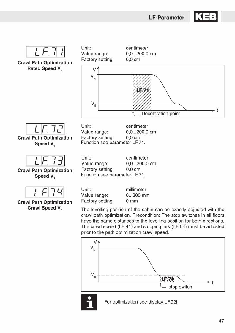
Unit: centimeterValue range: 0,0...200,0 cmFactory setting: 0,0 cm
Unit: centimeterValue range: 0,0...200,0 cmFactory setting: 0,0 cm
Unit: centimeterValue range: 0,0...200,0 cmFactory setting: 0,0 cm
VN
VE
tDeceleration point
V
Unit: millimeterValue range: 0...300 mmFactory setting: 0 mm
The levelling position of the cabin can be exactly adjusted with thecrawl path optimization. Precondition: The stop switches in all floorshave the same distances to the levelling position for both directions.The crawl speed (LF.41) and stopping jerk (LF.54) must be adjustedprior to the path optimization crawl speed.
VN
V
VE
tstop switch
For optimization see display LF.92!
LF.74LF.74
Crawl Path OptimizationRated Speed VN
Crawl Path OptimizationSpeed V1
Function see parameter LF.71.
Function see parameter LF.71.Crawl Path Optimization
Speed V2
Crawl Path OptimizationCrawl Speed VE
48
LF-Parameter
t
Delay point
V
VN
VE
t
Delay point
V
VN
VE
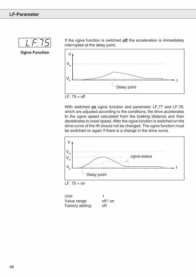
Unit: 1Value range: off / onFactory setting: off
LF. 75 = off
LF. 75 = on
VS
Ogive Function
If the ogive function is switched off the acceleration is immediatelyinterrupted at the delay point.
With switched on ogive function and parameter LF.77 and LF.78,which are adjusted according to the conditions, the drive acceleratesto the ogive speed calculated from the braking distance and thendecelerates to crawl speed. After the ogive function is switched on thedrive curve of the lift should not be changed. The ogive function mustbe switched on again if there is a change in the drive curve.
ogive-status
49
- All deceleration points must have the same distance to the floorlevels. Also at top- and bottom-floor.
- The distance of the deceleration points must be adjusted in LF.77first.
- The deceleration points should be set as far away as possible fromthe holding position, which is approached, so that the changeoverto crawl speed occurs in the lower half of the acceleration.
- Increase LF.50 and reduce LF.51 until the ogive ride can be carriedout or until no ogive ride is necessary.
- If possible, the values for starting jerk and acceleration shouldcorrespond to the values for deceleration jerk and deceleration.
- If the cabin overrides the holding position, adjust a smaller value inLF.77.
- If the crawl distance during the execution of the ogive ride is toolong, adjust a larger value in LF.77.
- If the crawl distance during a ride over several floors is too long,optimize it with LF.71.
- If the speed (LF.20, LF.42), the ramp values (LF.50 - LF.54) orthe braking distance (LF.77) were changed, the ogive function(LF.75) must be switched OFF and ON again.
We are quite prepared to calculate for you the best possible adjustment.Just send us a fax to #49 5263 / 401 – 116 or an email to [email protected].
For a calculation we require the following data:- Speed of the lift- Distance from deceleration point to levelling signal- All floor levels
Adjustment instructionsfor ogive function
LF-Parameter
50
t
Delay point
V
VN
VE
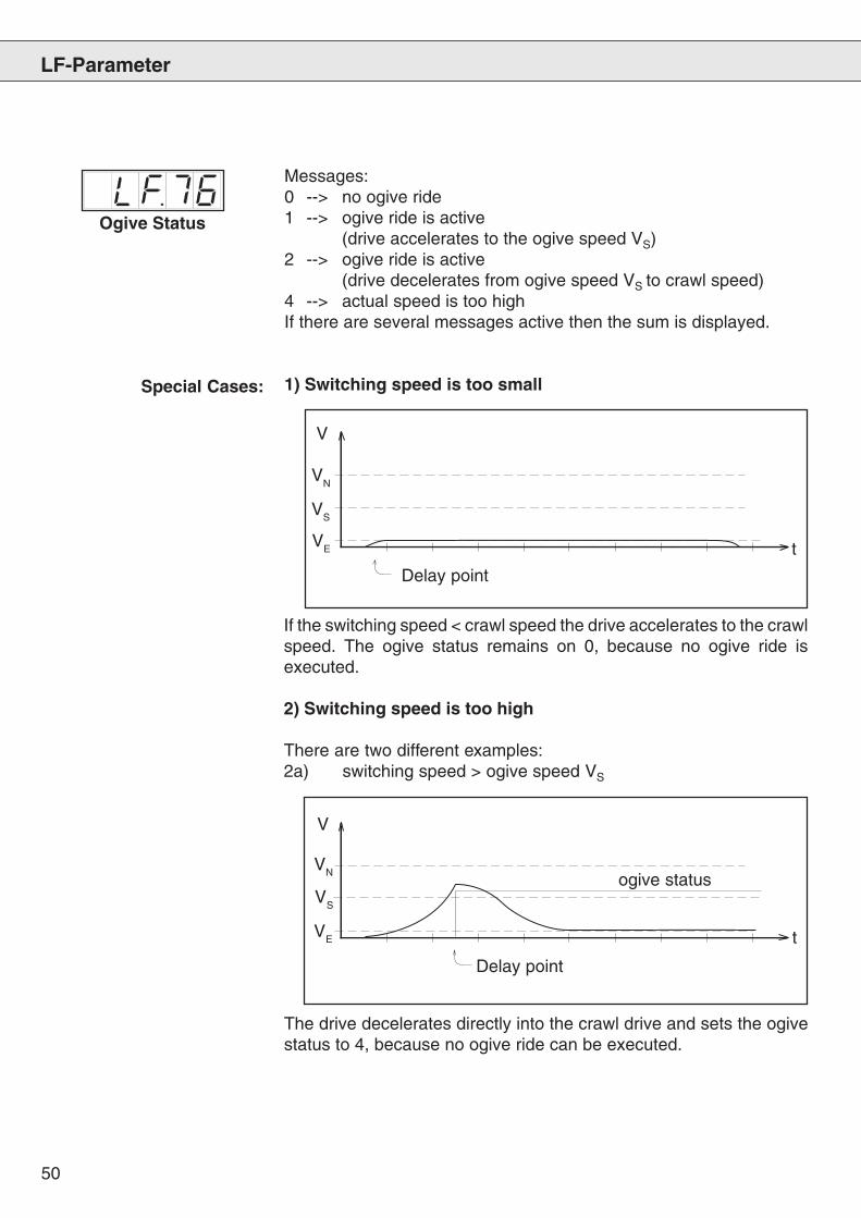
If the switching speed < crawl speed the drive accelerates to the crawlspeed. The ogive status remains on 0, because no ogive ride isexecuted.
2) Switching speed is too high
There are two different examples:2a) switching speed > ogive speed VS
t
Delay point
V
VN
VE
ogive status
VS
VS
LF-Parameter
Ogive Status
Messages:0 --> no ogive ride1 --> ogive ride is active
(drive accelerates to the ogive speed VS)2 --> ogive ride is active
(drive decelerates from ogive speed VS to crawl speed)4 --> actual speed is too highIf there are several messages active then the sum is displayed.
1) Switching speed is too smallSpecial Cases:
The drive decelerates directly into the crawl drive and sets the ogivestatus to 4, because no ogive ride can be executed.
51
LF-Parameter
t
Delay point
V
VN
VE
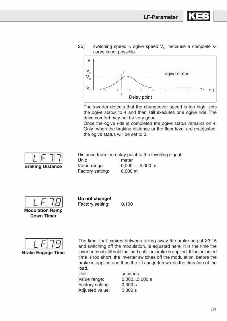
The inverter detects that the changeover speed is too high, setsthe ogive status to 4 and then still executes one ogive ride. Thedrive comfort may not be very good.Once the ogive ride is completed the ogive status remains on 4.Only when the braking distance or the floor level are readjusted,the ogive status will be set to 0.
ogive status
Distance from the delay point to the levelling signal.Unit: meterValue range: 0,000 … 5,000 mFactory setting: 0,000 m
VS
The time, that expires between taking away the brake output X3.15and switching off the modulation, is adjusted here. It is the time theinverter must still hold the load until the brake is applied. If the adjustedtime is too short, the inverter switches off the modulation, before thebrake is applied and thus the lift can jerk towards the direction of theload.Unit: secondsValue range: 0,000...3,000 sFactory setting: 0,300 sAdjusted value: 0,300 s
Brake Engage Time
2b) switching speed < ogive speed VS, because a complete s-curve is not possible.
Braking Distance
Do not change!Factory setting: 0,100
Modulation RampDown Timer
52
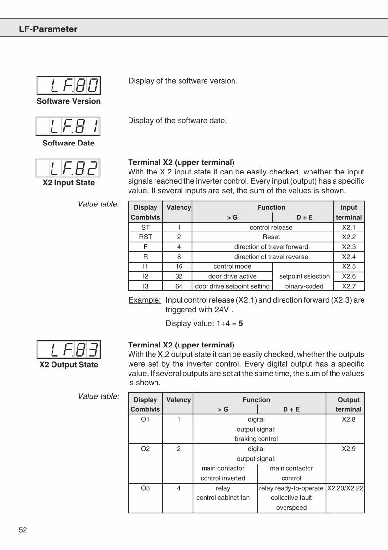
Display Valency Function Output
Combivis > G D + E terminal
O1 1 digital X2.8
output signal:
braking control
O2 2 digital X2.9
output signal:
main contactor main contactor
control inverted control
O3 4 relay relay ready-to-operate X2.20/X2.22
control cabinet fan collective fault
overspeed
Display Valency Function Input
Combivis > G D + E terminal
ST 1 control release X2.1
RST 2 Reset X2.2
F 4 direction of travel forward X2.3
R 8 direction of travel reverse X2.4
I1 16 control mode X2.5
I2 32 door drive active setpoint selection X2.6
I3 64 door drive setpoint setting binary-coded X2.7
LF-Parameter
X2 Input State
Terminal X2 (upper terminal)With the X.2 input state it can be easily checked, whether the inputsignals reached the inverter control. Every input (output) has a specificvalue. If several inputs are set, the sum of the values is shown.
Example: Input control release (X2.1) and direction forward (X2.3) aretriggered with 24V .
Display value: 1+4 = 5
X2 Output State
Terminal X2 (upper terminal)With the X.2 output state it can be easily checked, whether the outputswere set by the inverter control. Every digital output has a specificvalue. If several outputs are set at the same time, the sum of the valuesis shown.
Value table:
Value table:
Software Version
Software Date
Display of the software version.
Display of the software date.
53
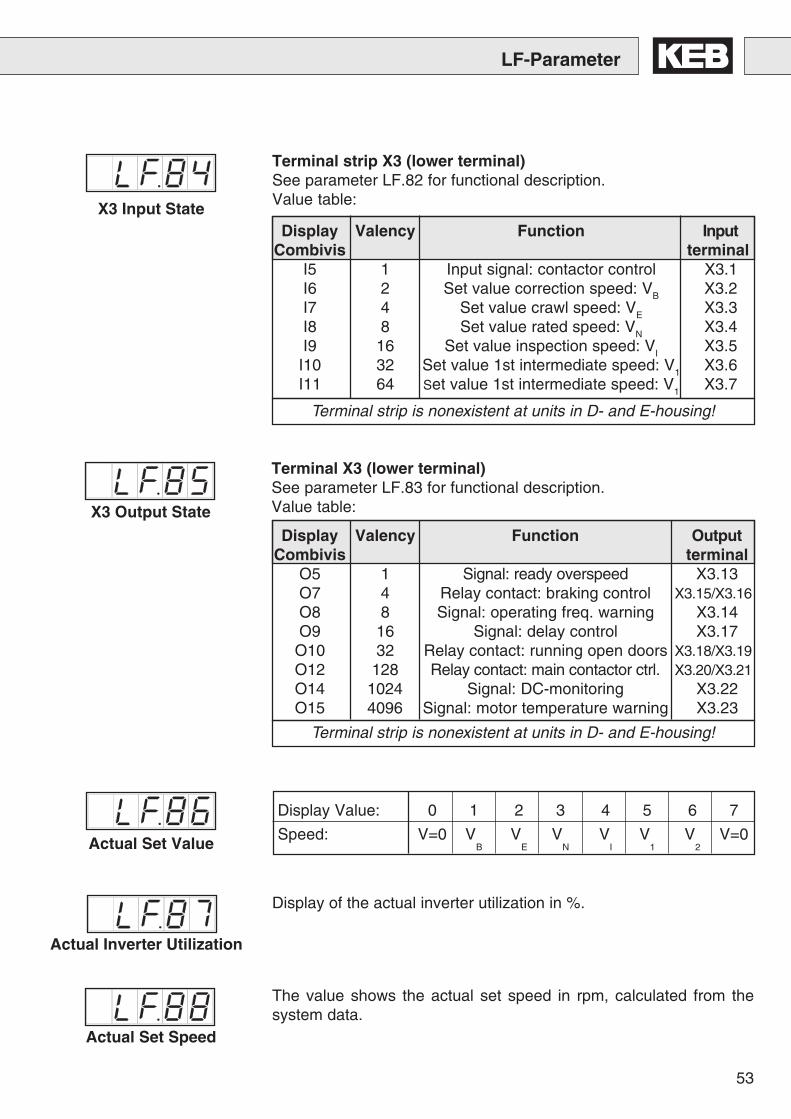
Terminal strip is nonexistent at units in D- and E-housing!
Terminal strip is nonexistent at units in D- and E-housing!
LF-Parameter
X3 Output State
Display Value: 0 1 2 3 4 5 6 7
Speed: V=0 VB
VE
VN
VI
V1
V2
V=0
Display Valency Function OutputCombivis terminal
O5 1 Signal: ready overspeed X3.13O7 4 Relay contact: braking control X3.15/X3.16O8 8 Signal: operating freq. warning X3.14O9 16 Signal: delay control X3.17
O10 32 Relay contact: running open doors X3.18/X3.19O12 128 Relay contact: main contactor ctrl. X3.20/X3.21O14 1024 Signal: DC-monitoring X3.22O15 4096 Signal: motor temperature warning X3.23
Display Valency Function InputCombivis terminal
I5 1 Input signal: contactor control X3.1I6 2 Set value correction speed: VB X3.2I7 4 Set value crawl speed: VE X3.3I8 8 Set value rated speed: VN X3.4I9 16 Set value inspection speed: VI X3.5
I10 32 Set value 1st intermediate speed: V1 X3.6I11 64 Set value 1st intermediate speed: V1 X3.7
X3 Input State
Terminal strip X3 (lower terminal)See parameter LF.82 for functional description.Value table:
Terminal X3 (lower terminal)See parameter LF.83 for functional description.Value table:
Actual Set Value
Actual Inverter Utilization
Display of the actual inverter utilization in %.
Actual Set Speed
The value shows the actual set speed in rpm, calculated from thesystem data.
54
Total Path
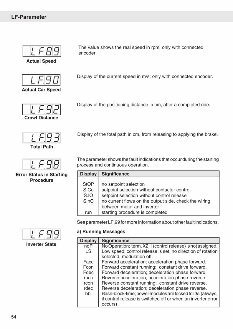
Display of the total path in cm, from releasing to applying the brake.
LF-Parameter
Display Significance
StOP no setpoint selectionS.Co setpoint selection without contactor controlS.IO setpoint selection without control releaseS.nC no current flows on the output side, check the wiring
between motor and inverterrun starting procedure is completed
Error Status in StartingProcedure
Display SignificancenoP No Operation; term. X2.1 (control release) is not assigned.LS Low speed; control release is set, no direction of rotation
selected, modulation off.Facc Forward acceleration; acceleration phase forward.Fcon Forward constant running; constant drive forward.Fdec Forward deceleration; deceleration phase forward.racc Reverse acceleration; acceleration phase reverse.rcon Reverse constant running; constant drive reverse.rdec Reverse deceleration; deceleration phase reverse.bbl Base-block-time; power modules are locked for 3s (always,
if control release is switched off or when an inverter erroroccurs) .
Actual Speed
The value shows the real speed in rpm, only with connectedencoder.
Actual Car Speed
Display of the current speed in m/s; only with connected encoder.
Crawl Distance
Display of the positioning distance in cm, after a completed ride.
The parameter shows the fault indications that occur during the startingprocess and continuous operation.
See parameter LF.99 for more information about other fault indications.
Inverter State
a) Running Messages
55
LF-Parameter
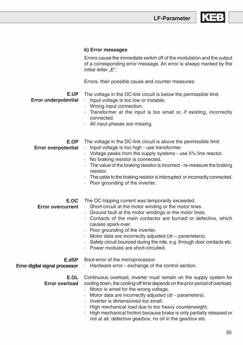
b) Error messages
Errors cause the immediate switch off of the modulation and the outputof a corresponding error message. An error is always marked by theinitial letter „E“.
Errors, their possible cause and counter measures:
E.UPError underpotential
E.OPError overpotential
E.OCError overcurrent
E.dSPError digital signal processor
E.OLError overload
The voltage in the DC-link circuit is below the permissible limit.· Input voltage is too low or instable.· Wrong input connection.· Transformer at the input is too small or, if existing, incorrectly
connected.· All input phases are missing.
The voltage in the DC-link circuit is above the permissible limit:· Input voltage is too high - use transformer.· Voltage peaks from the supply systems - use 5% line reactor.· No braking resistor is connected.· The value of the braking resistor is incorrect - re-measure the braking
resistor.· The cable to the braking resistor is interrupted or incorrectly connected.· Poor grounding of the inverter.
The OC-tripping current was temporarily exceeded.· Short-circuit at the motor winding or the motor lines.· Ground fault at the motor windings or the motor lines.· Contacts of the main contactor are burned or defective, which
causes spark-over.· Poor grounding of the inverter.· Motor data are incorrectly adjusted (dr – parameters).· Safety circuit bounced during the ride, e.g. through door contacts etc.· Power modules are short-circuited.
Boot-error of the microprocessor.· Hardware error - exchange of the control section.
Continuous overload, inverter must remain on the supply system forcooling down, the cooling-off time depends on the prior period of overload.· Motor is wired for the wrong voltage.· Motor data are incorrectly adjusted (dr - parameters).· Inverter is dimensioned too small.· High mechanical load due to too heavy counterweight.· High mechanical friction because brake is only partially released or
not at all, defective gearbox, no oil in the gearbox etc.
56
LF-Parameter
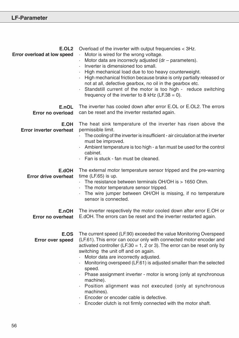
E.OL2Error overload at low speed
E.nOLError no overload
E.OHError inverter overheat
E.dOHError drive overheat
E.nOHError no overheat
E.OSError over speed
Overload of the inverter with output frequencies < 3Hz.· Motor is wired for the wrong voltage.· Motor data are incorrecly adjusted (dr – parameters).· Inverter is dimensioned too small.· High mechanical load due to too heavy counterweight.· High mechanical friction because brake is only partially released or
not at all, defective gearbox, no oil in the gearbox etc.· Standstill current of the motor is too high - reduce switching
frequency of the inverter to 8 kHz (LF.38 = 0).
The inverter has cooled down after error E.OL or E.OL2. The errorscan be reset and the inverter restarted again.
The heat sink temperature of the inverter has risen above thepermissible limit.· The cooling of the inverter is insufficient - air circulation at the inverter
must be improved.· Ambient temperature is too high - a fan must be used for the control
cabinet.· Fan is stuck - fan must be cleaned.
The external motor temperature sensor tripped and the pre-warningtime (LF.65) is up.· The resistance between terminals OH/OH is > 1650 Ohm.· The motor temperature sensor tripped.· The wire jumper between OH/OH is missing, if no temperature
sensor is connected.
The inverter respectively the motor cooled down after error E.OH orE.dOH. The errors can be reset and the inverter restarted again.
The current speed (LF.90) exceeded the value Monitoring Overspeed(LF.61). This error can occur only with connected motor encoder andactivated controller (LF.30 = 1, 2 or 3). The error can be reset only byswitching the unit off and on again.· Motor data are incorrectly adjusted.· Monitoring overspeed (LF.61) is adjusted smaller than the selected
speed.· Phase assignment inverter - motor is wrong (only at synchronous
machine).· Position alignment was not executed (only at synchronous
machines).· Encoder or encoder cable is defective.· Encoder clutch is not firmly connected with the motor shaft.
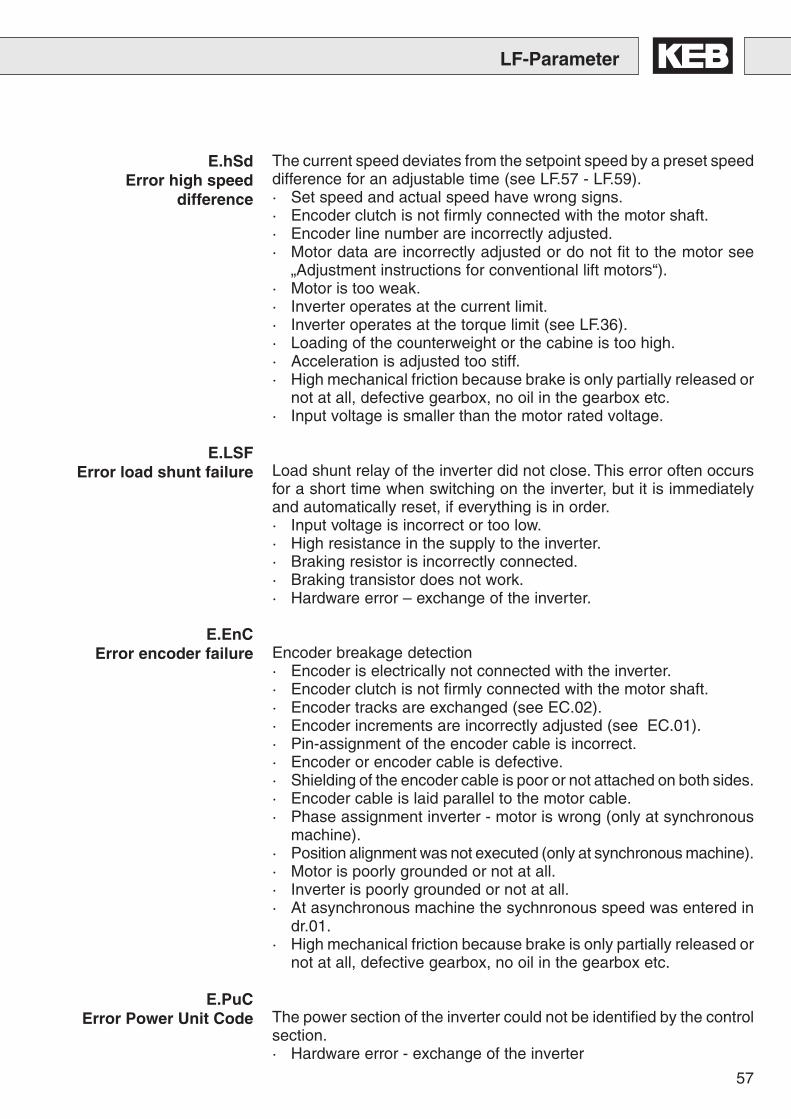
57
LF-Parameter
The current speed deviates from the setpoint speed by a preset speeddifference for an adjustable time (see LF.57 - LF.59).· Set speed and actual speed have wrong signs.· Encoder clutch is not firmly connected with the motor shaft.· Encoder line number are incorrectly adjusted.· Motor data are incorrectly adjusted or do not fit to the motor see
„Adjustment instructions for conventional lift motors“).· Motor is too weak.· Inverter operates at the current limit.· Inverter operates at the torque limit (see LF.36).· Loading of the counterweight or the cabine is too high.· Acceleration is adjusted too stiff.· High mechanical friction because brake is only partially released or
not at all, defective gearbox, no oil in the gearbox etc.· Input voltage is smaller than the motor rated voltage.
Load shunt relay of the inverter did not close. This error often occursfor a short time when switching on the inverter, but it is immediatelyand automatically reset, if everything is in order.· Input voltage is incorrect or too low.· High resistance in the supply to the inverter.· Braking resistor is incorrectly connected.· Braking transistor does not work.· Hardware error – exchange of the inverter.
Encoder breakage detection· Encoder is electrically not connected with the inverter.· Encoder clutch is not firmly connected with the motor shaft.· Encoder tracks are exchanged (see EC.02).· Encoder increments are incorrectly adjusted (see EC.01).· Pin-assignment of the encoder cable is incorrect.· Encoder or encoder cable is defective.· Shielding of the encoder cable is poor or not attached on both sides.· Encoder cable is laid parallel to the motor cable.· Phase assignment inverter - motor is wrong (only at synchronous
machine).· Position alignment was not executed (only at synchronous machine).· Motor is poorly grounded or not at all.· Inverter is poorly grounded or not at all.· At asynchronous machine the sychnronous speed was entered in
dr.01.· High mechanical friction because brake is only partially released or
not at all, defective gearbox, no oil in the gearbox etc.
The power section of the inverter could not be identified by the controlsection.· Hardware error - exchange of the inverter
E.hSdError high speed
difference
E.LSFError load shunt failure
E.EnCError encoder failure
E.PuCError Power Unit Code
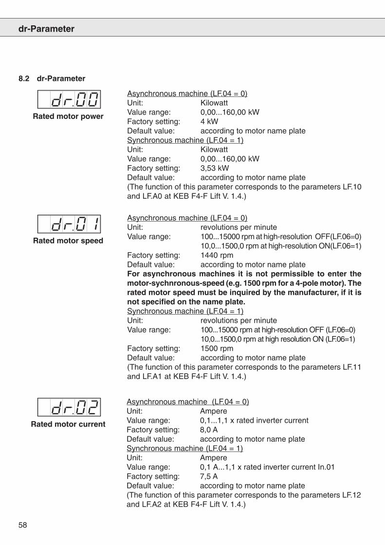
58
dr-Parameter
Rated motor power
Asynchronous machine (LF.04 = 0)Unit: KilowattValue range: 0,00...160,00 kWFactory setting: 4 kWDefault value: according to motor name plateSynchronous machine (LF.04 = 1)Unit: KilowattValue range: 0,00...160,00 kWFactory setting: 3,53 kWDefault value: according to motor name plate(The function of this parameter corresponds to the parameters LF.10and LF.A0 at KEB F4-F Lift V. 1.4.)
Rated motor speed
Asynchronous machine (LF.04 = 0)Unit: revolutions per minuteValue range: 100...15000 rpm at high-resolution OFF(LF.06=0)
10,0...1500,0 rpm at high-resolution ON(LF.06=1)Factory setting: 1440 rpmDefault value: according to motor name plateFor asynchronous machines it is not permissible to enter themotor-sychnronous-speed (e.g. 1500 rpm for a 4-pole motor). Therated motor speed must be inquired by the manufacturer, if it isnot specified on the name plate.Synchronous machine (LF.04 = 1)Unit: revolutions per minuteValue range: 100...15000 rpm at high-resolution OFF (LF.06=0)
10,0...1500,0 rpm at high resolution ON (LF.06=1)Factory setting: 1500 rpmDefault value: according to motor name plate(The function of this parameter corresponds to the parameters LF.11and LF.A1 at KEB F4-F Lift V. 1.4.)
Rated motor current
Asynchronous machine (LF.04 = 0)Unit: AmpereValue range: 0,1...1,1 x rated inverter currentFactory setting: 8,0 ADefault value: according to motor name plateSynchronous machine (LF.04 = 1)Unit: AmpereValue range: 0,1 A...1,1 x rated inverter current In.01Factory setting: 7,5 ADefault value: according to motor name plate(The function of this parameter corresponds to the parameters LF.12and LF.A2 at KEB F4-F Lift V. 1.4.)
8.2 dr-Parameter
59
dr-Parameter
Rated motor frequency
Asynchronous machine (LF.04 = 0)Unit: HertzValue range: 20...800 Hz at high-resolution OFF (LF.06 = 0)
2,0...80,0 Hz at high-resolution ON (LF.06 = 1)Factory setting: 50 HzDefault value: according to motor name plateSynchronous machine (LF.04 = 1)Unit: HertzValue range: 20...800 Hz at high-resolution OFF (LF.06 = 0)
2,0...80,0 Hz at high-resolution ON (LF.06 = 1)Factory setting: 75 HzDefault value: according to motor name plate
At synchronous machines the entered rated speed (dr.01) andthe entered rated frequency (dr.03) must fit to the number of polepairs of the motor.According to formula: n = f x 60 / p
(The function of this parameter corresponds to the parameters LF.15and LF.A3 at KEB F4-F Lift V. 1.4.)
Rated motor power factorcos phi
Asynchronous machine (LF.04 = 0)Unit: 1Value range: 0,05...1Factory setting: 0,86Default value: according to motor name plateThis parameter is not required for sychnronous machines and isnot indicated, if LF.04 = 1!
(The function of this parameter corresponds to the parameter LF.14 atKEB F4-F Lift V. 1.4.)
Static continuous current
Synchronous machine (LF.04 = 1)Unit: AmpereValue range: 0,1 A...1,1 x rated inverter current In.01Factory setting: 1,1 x rated motor current dr.02Default value: according to motor name plate
This parameter is not required for asynchronous machines andis not indicated, if LF.04 = 0 !
(The function of this parameter corresponds to the parameter LF.A4at KEB F4-F Lift V. 1.4.)
60
dr-Parameter
Asynchronous machine (LF.04 = 0)Unit: NewtonmeterAt asynchronous machines (LF.04 = 0) the rated motor torque iscalculated from the inverter and motor data. The calculated torque isindicated here and cannot be changed.Synchronous machine (LF.04 = 1)Unit: NewtonmeterValue range: 0,1...1000,0 Nm at high-resolution OFF (LF.06=0)
1...10000 Nm at high-resolution ON (LF.06=1)Factory setting: 7,5 NmDefault value: according to motor name plate(The function of this parameter corresponds to the parameters LF.91and LF.A5 at KEB F4-F Lift V. 1.4.)
Rated motor torque
Max. motor torque
The maximum motor torque is the torque which the inverter can makeavailable to motor, converted into current.
Asynchronous machine (LF.04 = 0)Unit: NewtonmeterAt asynchronous machines (LF.04 = 0) the maximum motor torque iscalculated from the inverter and motor data. The calculated torque isindicated here and cannot be changed.Synchronous machine (LF.04 = 1)Unit: NewtonmeterValue range: 0,1 Nm...dependent on inverter at
high-resolution OFF (LF.06 = 0)1 Nm...dependent on inverter athigh-resolution ON (LF.06 = 1)
Factory setting : dependent on inverterDefault value: according to motor name plate
Rated motor voltage
Asynchronous machine (LF.04 = 0)Unit: VoltValue range: 100...500 VFactory setting: 400 VDefault value: according to motor name plate
This parameter is not required for synchronous machines and isnot indicated, if LF.04 = 1 !
It is absolutely necessary to acknowledge this value with„Enter“, with that the pre-adjustments are calculated. Thisis also valid if the motor voltage is = 400 V.
(The function of this parameter corresponds to parameter LF.14 atKEB F4-F Lift V. 1.4.)
61
dr-Parameter
Asynchronous machine (LF.04 = 0)Unit: revolutions per minuteValue range: 200...6000 rpm at high-resolution OFF (LF.06=0)
25...750 rpm at high-resolution ON (LF.06=1)Factory setting: Value is automatically calculated after input of
rated motor voltage dr.12This parameter is not required for synchronous machines andnot indicated, if LF.04 = 1!
Corner speed formax. torque
Asynchronous machine (LF.04 = 0)Unit: revolutions per minuteValue range: 200...6000 rpm at high-resolution OFF (LF.06=0)
25...750 rpm at high-resolution ON (LF.06=1)Factory setting: Value is automatically calculated after input of
the rated motor voltage dr.12.This parameter is not required for synchronous machines andnot indicated, if LF.04 = 1!(The function of this parameter corresponds to parameter LF.16 atKEB F4-F Lift V. 1.4.)
Max. torque at dr.19
EMK voltage constant
Asynchronous machine (LF.04 = 0)Unit: NewtonmeterValue range: 0,0 Nm...maximum motor torque dr.10Factory setting: Value is automatically calculated after input of
rated motor voltage dr.12.This parameter is not required for synchronous machines andnot indicated, if LF.04 = 1!
Synchronous machine (LF.04 = 1)Unit: Volt per 1000 revolutions per minuteValue range: 0...8000 V / 1000 rpmFactory setting: 0 V / 1000 rpmDefault value: according to motor name plateThis parameter is not required for asynchronous machines andnot indicated, if LF.04 = 0!(The function of this parameter corresponds to parameter LF.A6 atKEB F4-F Lift V. 1.4.)
Corner speedfield weakening
The values dr.13 to dr.21 are pre-set by the inverter. Forthis purpose acknowledge dr.12!
62
dr-Parameter
Gain factorfield weakening
Asynchronous machine (LF.04 = 0)Unit: 1Value range: 0,10...2,00Factory setting: 1,2 – after input of the rated motor voltage dr.12
the value is reset automatically to the factorysetting.
This parameter is not required for synchronous machines andnot indicated, if LF.04 =1!
Flux adaptation
Synchronous machine (LF.04 = 1)Unit: MillihenryValue range: 0,1...100,0 mHFactory setting: 29,7 mHDefault value: according to motor name plate
This parameter is not required for asynchronous machines andnot indicated, if LF.04 = 0!(The function of this parameter corresponds to parameter LF.A8 atKEB F4-F Lift V. 1.4.)
Asynchronous machine (LF.04 = 0)Unit: percentValue range: 25...250 %Factory setting: 100 % – after input of the rated motor voltage
dr.12 the value is reset automatically to thefactory setting.
This parameter is not required for synchronous machines andnot indicated, if LF.04 = 1!
Winding resistance RU-V
Synchronous machine (LF.04 = 1)Unit: OhmValue range: 0,1...100,0 OhmFactory setting: 2,6 OhmDefault value: according to motor name plate
This parameter is not required for asynchronous machines andnot indicated, if LF.04 = 0!(The function of this parameter corresponds to parameter LF.A7 atKEB F4-F Lift V. 1.4.)
Winding inductance LU-V
63
dr-Parameter
8.3 EC-Parameter
This parameter indicates for which feedback systems the respectiveinverter is suited.
0 = Incremental and SinCos-encoder3 = Resolver
11 = Hiperface-encoder12 = UVW-encoder
(The function of this parameter corresponds to parameter In.56 atKEB F4.F Lift V1.4.)
Encoder interface 1(only display)
Pulse number Encoder 1
Track change Encoder 1
Unit: impulses per revolutionValue range: 256 … 10000 Imp/rpmFactory setting: 2048 Imp/rpmDefault value: according to motor name plate
(The function of this parameter corresponds to the parameters LF.17and LF.b0 at KEB F4.F Lift V1.4.)
With parameter EC.2 the encoder tracks of the incremental encodercan be exchanged by software.
Unit: 1Value range: off / onFactory setting: offDefault value: depending on encoder rotating field
(Also see "Start-up instruction manual")
The encoder track change can be executed at asynchronousmachines (LF.04 = 0 ) only.
(The function of this parameter corresponds to parameter LF.18 atKEB F4.F Lift V1.4.)
64
EC-Parameter
Encoder pole pairs
Here it is entered, whether the absolute information of the encoderrefers to the mechanical or electrical position of the motor.
Unit: 1Value range: 0:off / 1:onFactory setting: 0:offDefault value: 0:off = standard for Heidenhain ERN1387 or
similar, Resolver, Stegmann Hiperface1:on = for all encoders, where the commutationsignals are availabe in the same number as themotor pole pairs (like Hübner HOGS 15 DN 2048A12, all UVW-encoder).
The value for the encoder pole pairs can only be adjusted to 1:onwith the selection of synchronous machine (LF.04 = 1).
(The function of this parameter corresponds to parameter LF.b1 atKEB F4.F Lift V1.4.)
If the drive system (inverter and motor) is put into operation for the firsttime, the position of the encoder to the rotor position of the motor mustbe known.
By entering a 1 in EC.4 a system position adjustment is started. At thatthe drive must not be loaded (remove the ropes from the sheave).
During the adjustment the zero track is also checked. For this purposethe motor slowly completes one full revolution.
Value Meaning0 no position adjustment executed1 give drive command and hold until EC.4 = 52 automatic voltage increase until rated current flows
(motor is turned into the pole position)3 rotation check4 secure system position5 reset drive command6 Power-On-Reset, done by the inverter7 system position adjustment completed
The system position is displayed in EC.07 and saved.The system position adjustment can only be executed with theselection of synchronous machine (LF.04 = 1).
System positionadjustment
65
EC-Parameter
With this parameter the excitation frequency for the resolver is preset(only units with the part-no.: xx.F4.Fxx-xi4x).
Unit: KilohertzValue range: 5,00...10,00 kHzFactory setting: 8,00 kHzDefault value: depending on the type of resolver
Do not change the parameter!
Clock frequency encoder 1
Unit: 1Value range: 0 … 7Factory setting: 0Default value: 0 position adjustment off
1 position adjustment started
(The function of this parameter corresponds to parameter LF.b5 atKEB F4.F Lift V1.4. Since now one full revolution is necessary for theadjustment, the adjustment takes longer than with Version 1.4.)
Encoder 1 Mode
1. LF.06 = 0 + EC.06 = 0
2. LF.06 = 1 + EC.06 = 0
3. LF.06 = 0 + EC.06 = 1
4. LF.06 = 1 + EC.06 = 1
Here the high-resolution for SIN/COS-encoder can be adjusted.
Unit: 1Value range: 0:off / 1:onFactory setting: 0:offDefault value: depending on the type of encoder
Depending on the machine/encoder constellation following settingscan be selected for this parameter together with the parameter for thespeed-high-resolution (LF.06):
Recommended setting for motors with gearbox and incrementalencoder or resolver.
Adjustment not possible.
Encoder-high-resolution ON. Recommended setting for asynchronousmotors with gearbox and SIN-COS-encoder for excellent load-transfere.
Speed-high-resolution and encoder-high-resolution ON.Recommended setting for gearless motors with SIN/COS-encoder,Hiperface-encoder or UVW-encoder.
66
EC-Parameter
This parameter displays the position to the rotor position of the motor(also see EC.04).
If the system position of motor to encoder is known, then the systemadjustment described under EC.04 needs not to be executed. Theposition value can be entered directly in parameter EC.07.
To save the entered system position, the inverter mustbe switched off and on again!
Unit: 1Value range: 0...FFFFhexFactory setting: 4A49hexDefault value: depending on the encoder position
The value for the system position can be entered only with theselection of synchronous machine (LF.04 = 1).
(The function of this parameter corresponds to parameter LF.b2 atKEB F4.F Lift V1.4.)
System position
Speed sampling timeEncoder 1
Filter time for speed-feedback.
Unit: 1Value range: 0...5Factory setting: 3 ^ 4 ms
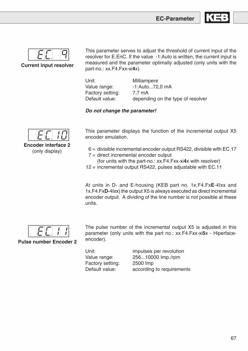
67
EC-Parameter
This parameter serves to adjust the threshold of current input of theresolver for E.EnC. If the value -1:Auto is written, the current input ismeasured and the parameter optimally adjusted (only units with thepart-no.: xx.F4.Fxx-xi4x).
Unit: MilliampereValue range: -1:Auto...72,0 mAFactory setting: 7,7 mADefault value: depending on the type of resolver
Do not change the parameter!
Current input resolver
This parameter displays the function of the incremental output X5encoder emulation.
6 = divisible incremental encoder output RS422, divisible with EC.177 = direct incremental encoder output
(for units with the part-no.: xx.F4.Fxx-xi4x with resolver)12 = incremental output RS422, pulses adjustable with EC.11
At units in D- and E-housing (KEB part no. 1x.F4.FxE-4Ixx and1x.F4.FxD-4Ixx) the output X5 is always executed as direct incrementalencoder output. A dividing of the line number is not possible at theseunits.
The pulse number of the incremental output X5 is adjusted in thisparameter (only units with the part no.: xx.F4.Fxx-xi5x - Hiperface-encoder).
Unit: impulses per revolutionValue range: 256...10000 Imp./rpmFactory setting: 2500 ImpDefault value: according to requirements
Encoder interface 2(only display)
Pulse number Encoder 2
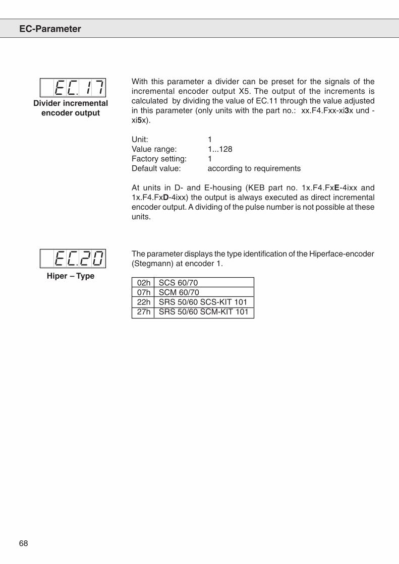
68
EC-Parameter
With this parameter a divider can be preset for the signals of theincremental encoder output X5. The output of the increments iscalculated by dividing the value of EC.11 through the value adjustedin this parameter (only units with the part no.: xx.F4.Fxx-xi3x und -xi5x).
Unit: 1Value range: 1...128Factory setting: 1Default value: according to requirements
At units in D- and E-housing (KEB part no. 1x.F4.FxE-4ixx and1x.F4.FxD-4ixx) the output is always executed as direct incrementalencoder output. A dividing of the pulse number is not possible at theseunits.
Divider incrementalencoder output
The parameter displays the type identification of the Hiperface-encoder(Stegmann) at encoder 1.
02h SCS 60/7007h SCM 60/7022h SRS 50/60 SCS-KIT 10127h SRS 50/60 SCM-KIT 101
Hiper – Type
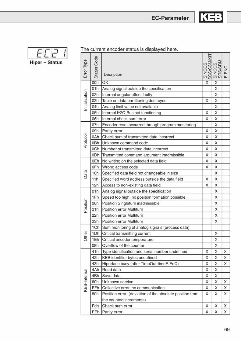
69
00h OK X X
01h Analog signal outside the specification X
02h Internal angular offset faulty X
03h Table on data partitioning destroyed X X
04h Analog limit value not available X
05h Internal I^2C-Bus not functioning X X
06h Internal check sum error X X
07h Encoder reset occurred through program monitoring X
09h Parity error X X
0Ah Check sum of transmitted data incorrect X X
0Bh Unknown command code X X
0Ch Number of transmitted data incorrect X X
0Dh Transmitted command argument inadmissible X X
0Eh No writing on the selected data field X X
0Fh Wrong access code X X
10h Specified data field not changeable in size X
11h Specified word address outside the data field X X
12h Access to non-existing data field X X
01h Analog signal outside the specification X
1Fh Speed too high, no position formation possible X
20h Position Singleturn inadmissible X
21h Position error Multiturn X
22h Position error Multiturn X
23h Position error Multiturn X
1Ch Sum monitoring of analog signals (process data)
1Dh Critical transmitting current X
1Eh Critical encoder temperature X
08h Overflow of the counter X
41h Type identification and serial number undefined X X X
42h KEB identifier bytes undefined X X X
43h Hiperface busy (after TimeOut-timeE.EnC) X X X
4Ah Read data X X
4Bh Save data X X
60h Unknown service X X X
FFh Collective error, no communication X X X
80h Position error (deviation of the absolute position from X X X
the counted increments)
Fdh Check sum error X X X
FEh Parity error X X X
The current encoder status is displayed here.
Decription
E
rror
Typ
e
Sta
tus
Cod
e
SIN
CO
S S
CS
/SC
M/K
IT S
INC
OS
SR
S/S
RM
Ini
tializ
atio
n P
roto
col
Dat
a P
ositi
on O
ther
KE
B-I
nter
nal
E.E
NC
Hiper – Status
EC-Parameter
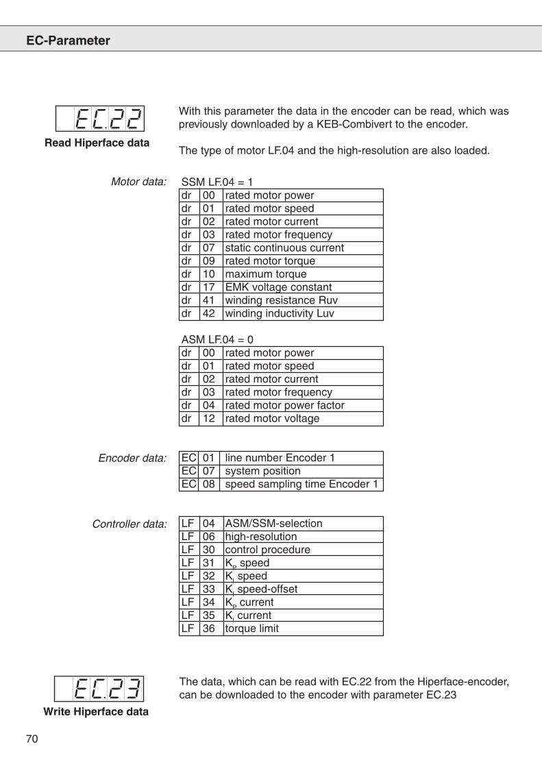
70
Read Hiperface data
EC-Parameter
With this parameter the data in the encoder can be read, which waspreviously downloaded by a KEB-Combivert to the encoder.
The type of motor LF.04 and the high-resolution are also loaded.
Motor data: SSM LF.04 = 1dr 00 rated motor powerdr 01 rated motor speeddr 02 rated motor currentdr 03 rated motor frequencydr 07 static continuous currentdr 09 rated motor torquedr 10 maximum torquedr 17 EMK voltage constantdr 41 winding resistance Ruvdr 42 winding inductivity Luv
ASM LF.04 = 0dr 00 rated motor powerdr 01 rated motor speeddr 02 rated motor currentdr 03 rated motor frequencydr 04 rated motor power factordr 12 rated motor voltage
EC 01 line number Encoder 1EC 07 system positionEC 08 speed sampling time Encoder 1
LF 04 ASM/SSM-selectionLF 06 high-resolutionLF 30 control procedureLF 31 KP speedLF 32 KI speedLF 33 KI speed-offsetLF 34 KP currentLF 35 KI currentLF 36 torque limit
Encoder data:
Controller data:
Write Hiperface data
The data, which can be read with EC.22 from the Hiperface-encoder,can be downloaded to the encoder with parameter EC.23
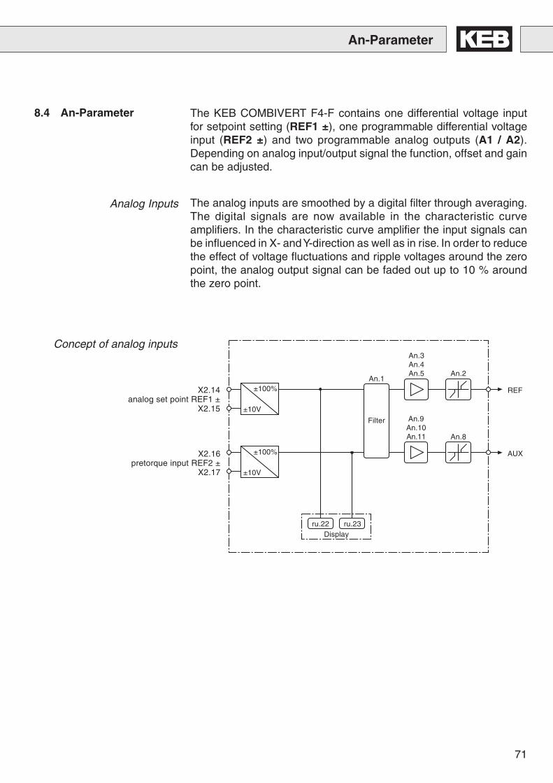
71
An-Parameter
8.4 An-Parameter The KEB COMBIVERT F4-F contains one differential voltage inputfor setpoint setting (REF1 ±), one programmable differential voltageinput (REF2 ±) and two programmable analog outputs (A1 / A2).Depending on analog input/output signal the function, offset and gaincan be adjusted.
Analog Inputs The analog inputs are smoothed by a digital filter through averaging.The digital signals are now available in the characteristic curveamplifiers. In the characteristic curve amplifier the input signals canbe influenced in X- and Y-direction as well as in rise. In order to reducethe effect of voltage fluctuations and ripple voltages around the zeropoint, the analog output signal can be faded out up to 10 % aroundthe zero point.
REF
AUX
±100%
±10V
±100%
±10V
An.1
Filter
An.3An.4An.5
An.9An.10An.11
An.2
An.8
ru.22 ru.23
Concept of analog inputs
Display
X2.14analog set point REF1 ±
X2.15
X2.16pretorque input REF2 ±
X2.17
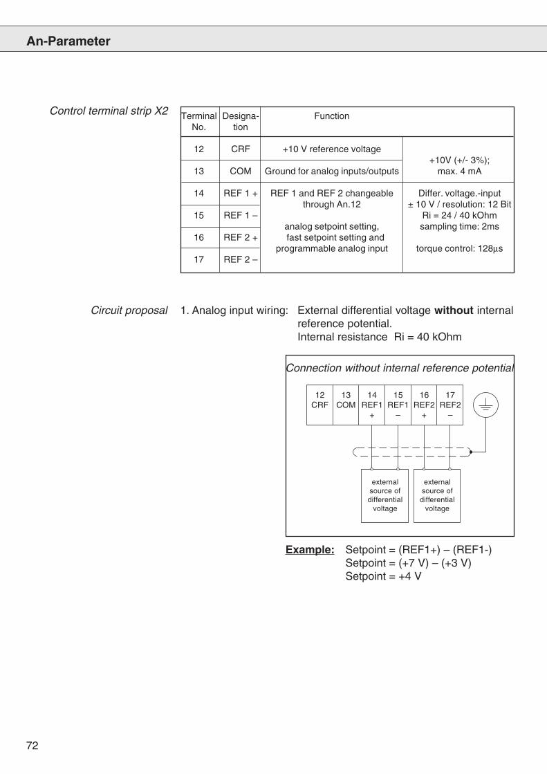
72
An-Parameter
12 13 14 15 16 17CRF COM REF1 REF1 REF2 REF2
+ – + –
Control terminal strip X2 Terminal Designa- FunctionNo. tion
12 CRF +10 V reference voltage+10V (+/- 3%);
13 COM Ground for analog inputs/outputs max. 4 mA
14 REF 1 + REF 1 and REF 2 changeable Differ. voltage.-inputthrough An.12 ± 10 V / resolution: 12 Bit
15 REF 1 – Ri = 24 / 40 kOhmanalog setpoint setting, sampling time: 2ms
16 REF 2 + fast setpoint setting andprogrammable analog input torque control: 128µs
17 REF 2 –
Circuit proposal 1. Analog input wiring: External differential voltage without internalreference potential.Internal resistance Ri = 40 kOhm
externalsource ofdifferential
voltage
externalsource ofdifferential
voltage
Connection without internal reference potential
Example: Setpoint = (REF1+) – (REF1-)Setpoint = (+7 V) – (+3 V)Setpoint = +4 V
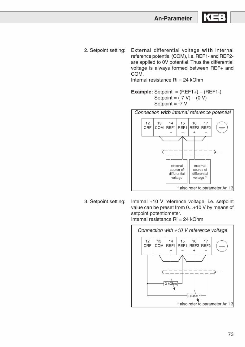
73
12 13 14 15 16 17CRF COM REF1 REF1 REF2 REF2
+ – + –
12 13 14 15 16 17CRF COM REF1 REF1 REF2 REF2
+ – + –
3 kOhm
3 kOhm *)
2. Setpoint setting: External differential voltage with internalreference potential (COM), i.e. REF1- and REF2-are applied to 0V potential. Thus the differentialvoltage is always formed between REF+ andCOM.Internal resistance Ri = 24 kOhm
Example: Setpoint = (REF1+) – (REF1-)Setpoint = (-7 V) – (0 V)Setpoint = -7 V
externalsource ofdifferential
voltage
externalsource ofdifferentialvoltage *)
Connection with internal reference potential
3. Setpoint setting: Internal +10 V reference voltage, i.e. setpointvalue can be preset from 0...+10 V by means ofsetpoint potentiometer.Internal resistance Ri = 24 kOhm
Connection with +10 V reference voltage
An-Parameter
* also refer to parameter An.13
* also refer to parameter An.13
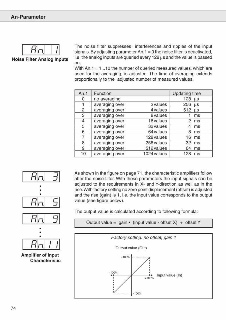
74
An-Parameter
+100%
+100%
-100%
-100%
The noise filter suppresses interferences and ripples of the inputsignals. By adjusting parameter An.1 = 0 the noise filter is deactivated,i.e. the analog inputs are queried every 128 µs and the value is passedon.With An.1 = 1...10 the number of queried measured values, which areused for the averaging, is adjusted. The time of averaging extendsproportionally to the adjusted number of measured values.
Noise Filter Analog Inputs
Amplifier of InputCharacteristic
As shown in the figure on page 71, the characteristic amplifiers followafter the noise filter. With these parameters the input signals can beadjusted to the requirements in X- and Y-direction as well as in therise. With factory setting no zero point displacement (offset) is adjustedand the rise (gain) is 1, i.e. the input value corresponds to the outputvalue (see figure below).
The output value is calculated according to following formula:
Output value = gain • (input value - offset X) + offset Y
Input value (In)
Output value (Out)
Factory setting: no offset, gain 1
An.1 Function Updating time0 no averaging 128 µs1 averaging over 2values 256 µs2 averaging over 4values 512 µs3 averaging over 8values 1 ms4 averaging over 16values 2 ms5 averaging over 32values 4 ms6 averaging over 64values 8 ms7 averaging over 128values 16 ms8 averaging over 256values 32 ms9 averaging over 512values 64 ms
10 averaging over 1024values 128 ms
•••
•••
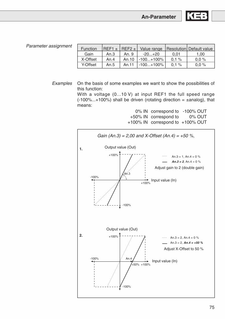
75
�����
�����
����
���� ��
����
�����
�����
����
�������
An-Parameter
1.
2.
An.3 = 1, An.4 = 0 %
An.3 = 2, An.4 = 0 %
An.3 = 2, An.4 = 0 %
An.3 = 2, An.4 = +50 %
On the basis of some examples we want to show the possibilities ofthis function:With a voltage (0...10 V) at input REF1 the full speed range(-100%...+100%) shall be driven (rotating direction = ±analog), thatmeans:
Parameter assignment
Examples
Gain (An.3) = 2,00 and X-Offset (An.4) = +50 %,
Function REF1 ± REF2 ± Value range Resolution Default valueGain An.3 An. 9 -20...+20 0,01 1,00
X-Offset An.4 An.10 -100...+100% 0,1 % 0,0 %Y-Offset An.5 An.11 -100...+100% 0,1 % 0,0 %
Adjust gain to 2 (double gain)
Adjust X-Offset to 50 %
0% IN correspond to -100% OUT+50% IN correspond to 0% OUT
+100% IN correspond to +100% OUT
Input value (In)
Output value (Out)
Input value (In)
Output value (Out)

76
An-Parameter
�����
�����
����
����
���
�����
�����
����
����
��
����
1.
2.
An.3 = +1, An.4 = 0%, An.5 = 0%
An.3 = -1, An.4 = 0%, An.5 = 0%
An.3 = -1, An.4 = 0%, An.5 = 0%
An.3 = -1, An.4 = +75%, An.5 = 0%
�����
�����
����
����
��������
3.
An.3 = -1, An.4 = +75%, An.5 = 0%
An.3 = -1, An.4 = +75%, An.5 = +100%
Gain (An.3)= -1, X-Offset (An.4)= +75%, Y-Offset (An.5)= +100%
Following values are to be adjusted for input REF1 ± :1. adjust the gain to -1 (single gain);2. adjust X-Offset to 75 % ;3. adjust Y-Offset to 100 % .
2. Example
With these settings and inverted setpoint setting in the range of+75...+100 % IN over input REF1 ± a speed range of +100...+75%OUT can be driven, that means:
0% IN correspond to +100% OUT+75% IN correspond to +100% OUT
+100% IN correspond to +75% OUTIn order to avoid wrong programming of the inputs signals, the IN /OUT adjustment should be checked with a control diagram (see above).
Input value (In)
Output value (Out)
Input value (In)
Output value (Out)
Input value (In)
Output value (Out)
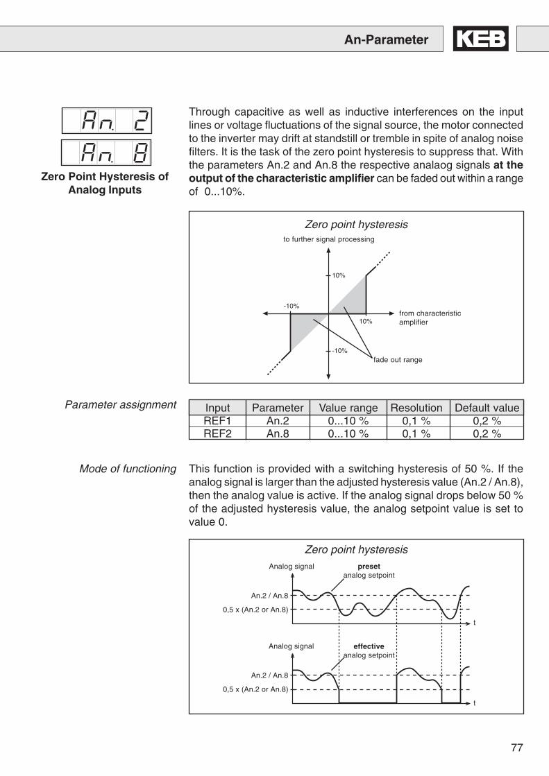
77
An-Parameter
-10%
10%
10%
-10%
t
t
Through capacitive as well as inductive interferences on the inputlines or voltage fluctuations of the signal source, the motor connectedto the inverter may drift at standstill or tremble in spite of analog noisefilters. It is the task of the zero point hysteresis to suppress that. Withthe parameters An.2 and An.8 the respective analaog signals at theoutput of the characteristic amplifier can be faded out within a rangeof 0...10%.
Zero Point Hysteresis ofAnalog Inputs
This function is provided with a switching hysteresis of 50 %. If theanalog signal is larger than the adjusted hysteresis value (An.2 / An.8),then the analog value is active. If the analog signal drops below 50 %of the adjusted hysteresis value, the analog setpoint value is set tovalue 0.
from characteristicamplifier
to further signal processing
fade out range
Zero point hysteresis
Zero point hysteresisAnalog signal
Analog signal
presetanalog setpoint
effectiveanalog setpoint
An.2 / An.8
0,5 x (An.2 or An.8)
An.2 / An.8
0,5 x (An.2 or An.8)
Mode of functioning
Input Parameter Value range Resolution Default valueREF1 An.2 0...10 % 0,1 % 0,2 %REF2 An.8 0...10 % 0,1 % 0,2 %
Parameter assignment
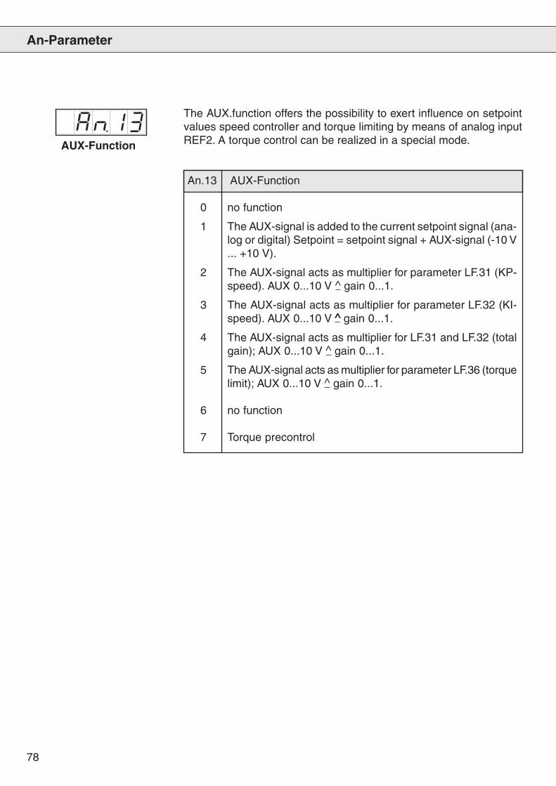
78
An-Parameter
AUX-Function
The AUX.function offers the possibility to exert influence on setpointvalues speed controller and torque limiting by means of analog inputREF2. A torque control can be realized in a special mode.
An.13 AUX-Function
0 no function
1 The AUX-signal is added to the current setpoint signal (ana-log or digital) Setpoint = setpoint signal + AUX-signal (-10 V... +10 V).
2 The AUX-signal acts as multiplier for parameter LF.31 (KP-speed). AUX 0...10 V ^ gain 0...1.
3 The AUX-signal acts as multiplier for parameter LF.32 (KI-speed). AUX 0...10 V ^̂ gain 0...1.
4 The AUX-signal acts as multiplier for LF.31 and LF.32 (totalgain); AUX 0...10 V ^ gain 0...1.
5 The AUX-signal acts as multiplier for parameter LF.36 (torquelimit); AUX 0...10 V ^ gain 0...1.
6 no function
7 Torque precontrol
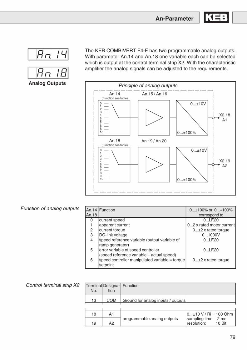
79
An-Parameter
Terminal Designa- FunctionNo. tion
13 COM Ground for analog inputs / outputs
18 A1 0...±10 V / Ri = 100 Ohmprogrammable analog outputs sampling time: 2 ms
19 A2 resolution: 10 Bit
An.14 Function 0...±100% or 0...+100%An.18 correspond to
0 current speed 0...LF.201 apparent current 0...2 x rated motor current2 current torque 0...±2 x rated torque3 DC-link voltage 0...1000V4 speed reference variable (output variable of 0...LF.20
ramp generator)5 error variable of speed controller 0...LF.20
(speed reference variable – actual speed)6 speed controller manipulated variable = torque 0...±2 x rated torque
setpoint
The KEB COMBIVERT F4-F has two programmable analog outputs.With parameter An.14 and An.18 one variable each can be selectedwhich is output at the control terminal strip X2. With the characteristicamplifier the analog signals can be adjusted to the requirements.
Analog Outputs
012345678910
012345678910
Principle of analog outputs
An.14(Function see table)
An.18(Function see table)
An.15 / An.16
An.19 / An.20
0...±100%
0...±10V
0...±100%
0...±10V
X2.18A1
X2.19A2
Function of analog outputs
Control terminal strip X2
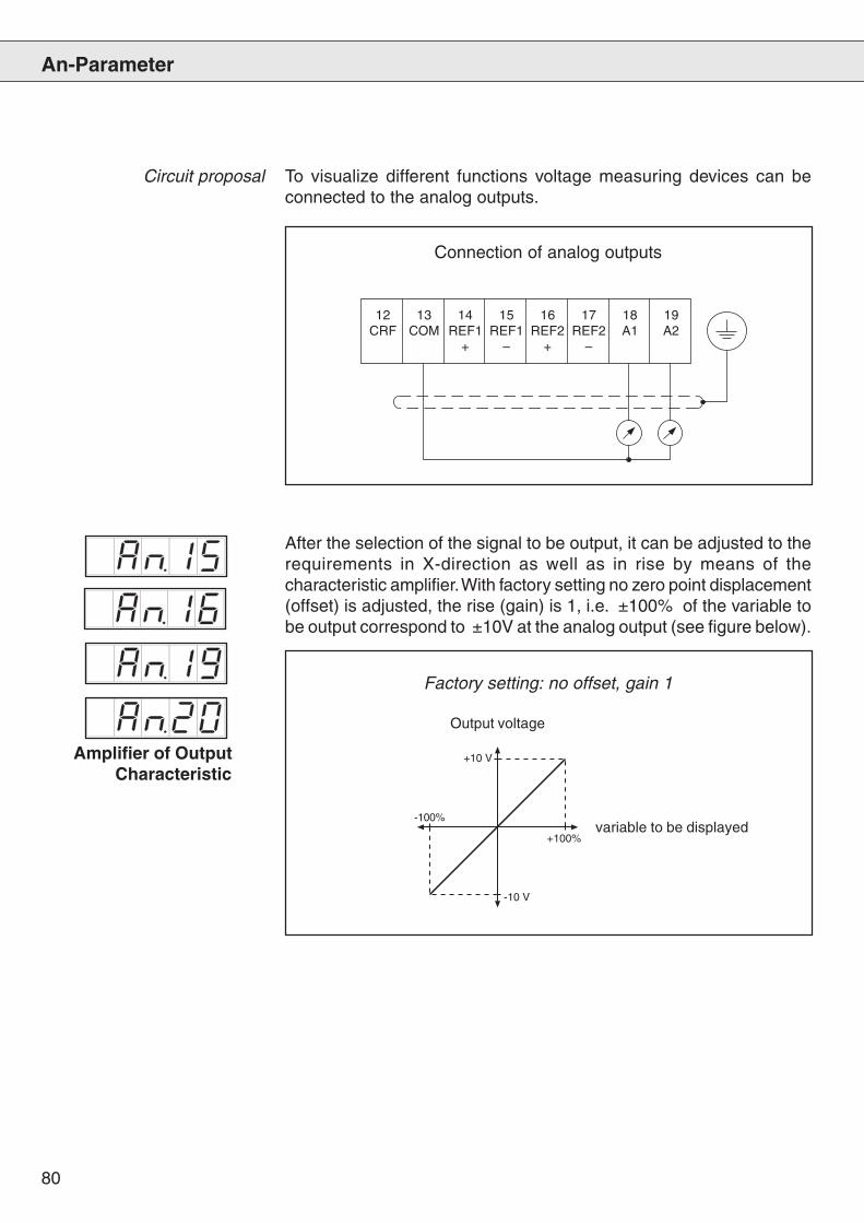
80
12 13 14 15 16 17 18 19CRF COM REF1 REF1 REF2 REF2 A1 A2
+ – + –
Circuit proposal To visualize different functions voltage measuring devices can beconnected to the analog outputs.
Connection of analog outputs
+10 V
+100%
-10 V
-100%
Amplifier of OutputCharacteristic
After the selection of the signal to be output, it can be adjusted to therequirements in X-direction as well as in rise by means of thecharacteristic amplifier. With factory setting no zero point displacement(offset) is adjusted, the rise (gain) is 1, i.e. ±100% of the variable tobe output correspond to ±10V at the analog output (see figure below).
variable to be displayed
Output voltage
Factory setting: no offset, gain 1
An-Parameter
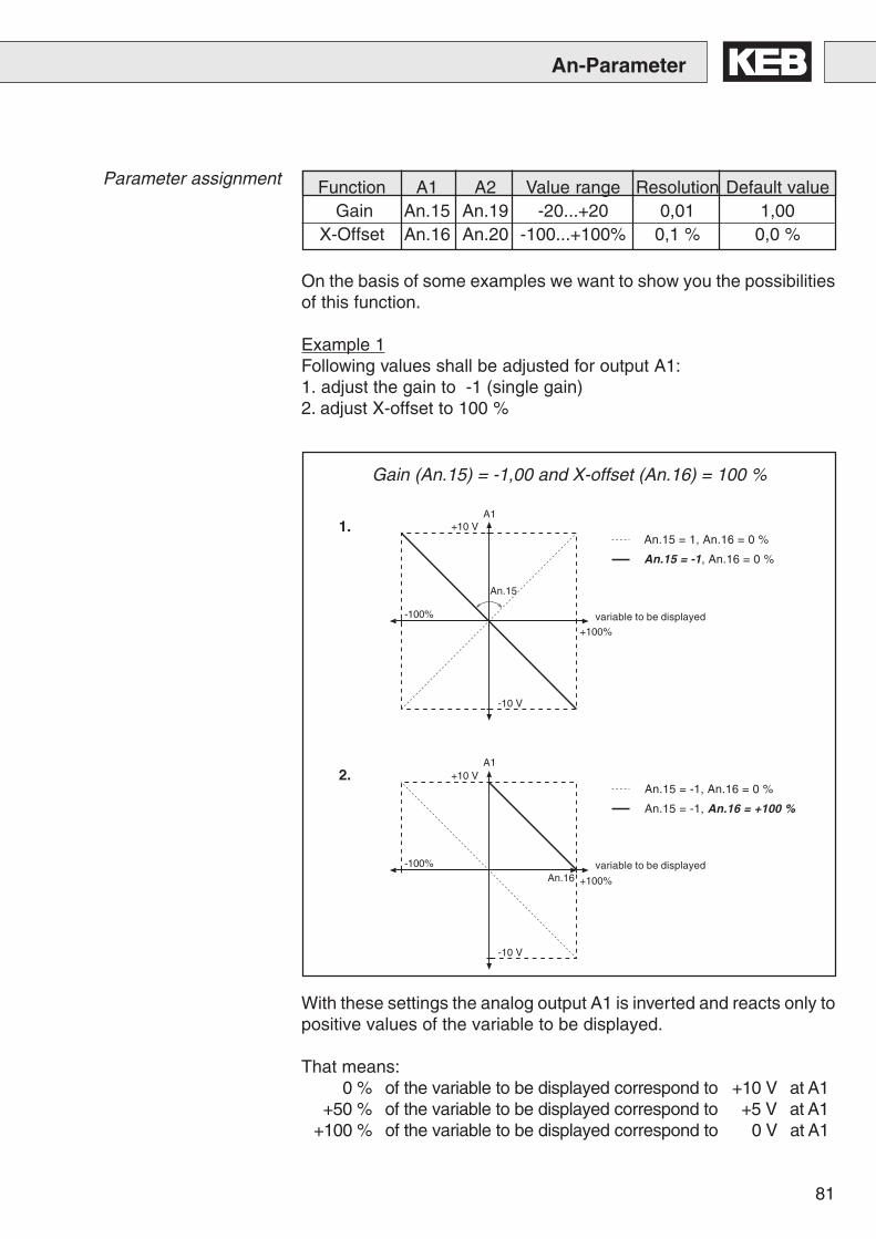
81
Function A1 A2 Value range Resolution Default value Gain An.15 An.19 -20...+20 0,01 1,00
X-Offset An.16 An.20 -100...+100% 0,1 % 0,0 %
+10 V
+100%
-10 V
-100%
An.15
An.15 = 1, An.16 = 0 %
An.15 = -1, An.16 = 0 %
With these settings the analog output A1 is inverted and reacts only topositive values of the variable to be displayed.
That means:0 % of the variable to be displayed correspond to +10 V at A1
+50 % of the variable to be displayed correspond to +5 V at A1+100 % of the variable to be displayed correspond to 0 V at A1
Gain (An.15) = -1,00 and X-offset (An.16) = 100 %
On the basis of some examples we want to show you the possibilitiesof this function.
Example 1Following values shall be adjusted for output A1:1. adjust the gain to -1 (single gain)2. adjust X-offset to 100 %
+10 V
+100%
-10 V
-100%An.16
1.
2.An.15 = -1, An.16 = 0 %
An.15 = -1, An.16 = +100 %
variable to be displayed
variable to be displayed
A1
A1
An-Parameter
Parameter assignment
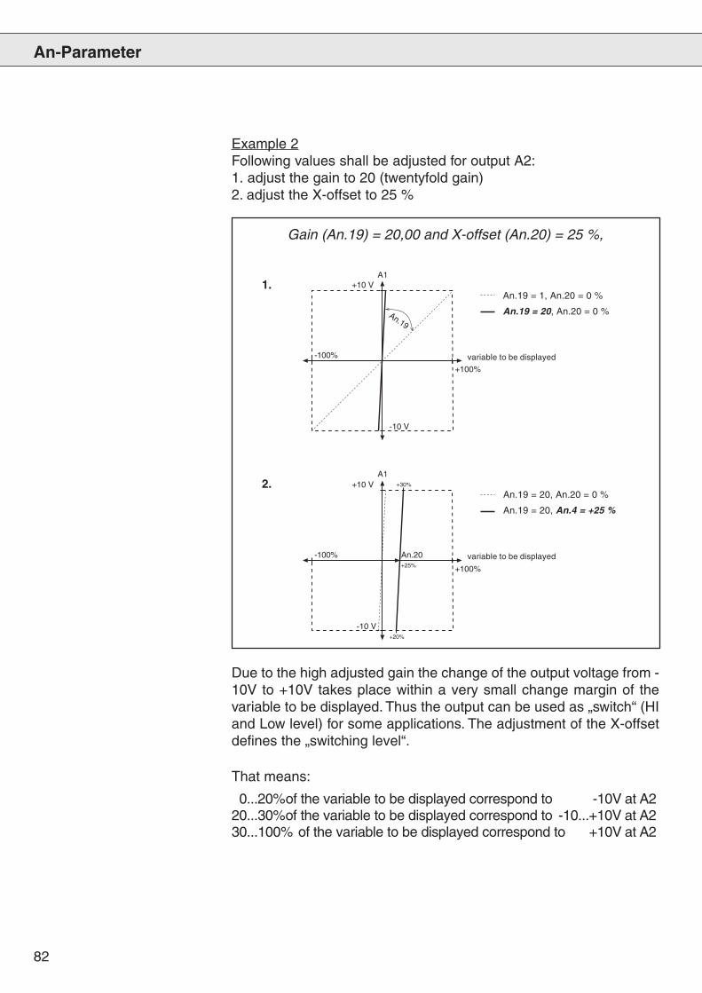
82
+10 V
+100%
-10 V
-100%
An.19
An.19 = 1, An.20 = 0 %
An.19 = 20, An.20 = 0 %
Due to the high adjusted gain the change of the output voltage from -10V to +10V takes place within a very small change margin of thevariable to be displayed. Thus the output can be used as „switch“ (HIand Low level) for some applications. The adjustment of the X-offsetdefines the „switching level“.
Gain (An.19) = 20,00 and X-offset (An.20) = 25 %,
Example 2Following values shall be adjusted for output A2:1. adjust the gain to 20 (twentyfold gain)2. adjust the X-offset to 25 %
+10 V
+100%
-10 V
-100% An.20
+20%
+25%
+30%
1.
2.An.19 = 20, An.20 = 0 %
An.19 = 20, An.4 = +25 %
variable to be displayed
variable to be displayed
A1
A1
An-Parameter
That means:
0...20%of the variable to be displayed correspond to -10V at A220...30%of the variable to be displayed correspond to -10...+10V at A230...100% of the variable to be displayed correspond to +10V at A2
83
ru-Parameter
8.5 ru-Parameter
Shows the actual inverter status.
See status/error messages parameter LF.99.
ru.8 makes it possible to immediately detect peak utilization within anoperating cycle. In addition the highest value that occurs in LF.87 isstored in ru.8. The peak memory can be deleted by pressing the UP orDOWN key, or with Bus by writing any value onto the address of ru. 8.The memory is deleted when the inverter is switched off.
The actual operating condition of the inverter can be read in theseparameters. The parameters in this group are read-only. Exception:parameters ru.8, ru.12 and ru.25 can be reset with the serial interfaceby entering any value. You can also use the keyboard and do the resetwith the UP/DOWN keys.
Display Inverter Status
In ru. 4 the set speed value, at the output of the ramp generator, isdisplayed. If the modulation is switched off or abnormal operating stateis active, then the actual setpoint 0 rpm is shown. During controlledoperation this parameter shows the output frequency calculated inrpm.
Displays actual motor torque in Nm (calculated from the active current).Max. tolerance approx. +/-20% in the basic speed range (in the fieldweakening range larger tolerances are possible). During open loopoperation 0 is always shown.Actual Torque Display
Set Speed Display
Peak Inverter Utilization
Display Actual Speed
The value shows the actual speed in rpm, only with connected speedencoder.
Display Setpoint Torque
The actual torque setpoint in Nm of the motor is displayed in ru.5.
Display of the actual apparent current. Resolution 0.1AApparent Current
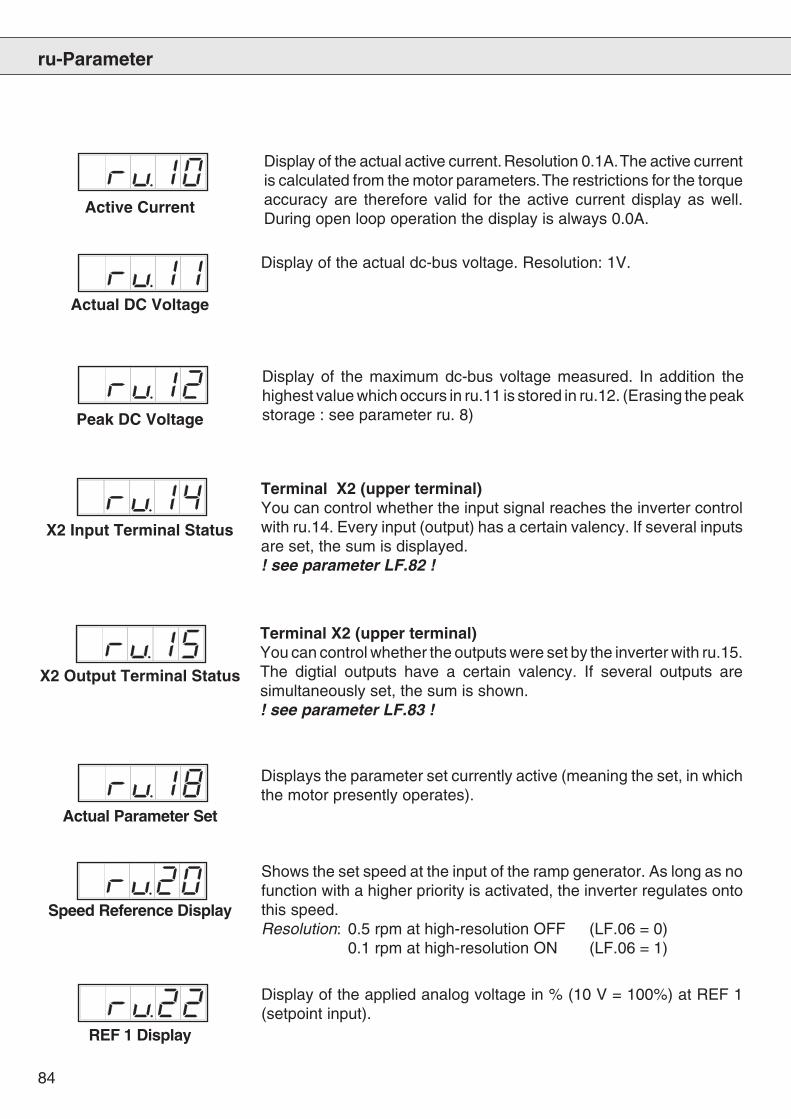
84
ru-Parameter
Display of the maximum dc-bus voltage measured. In addition thehighest value which occurs in ru.11 is stored in ru.12. (Erasing the peakstorage : see parameter ru. 8)
Display of the actual active current. Resolution 0.1A. The active currentis calculated from the motor parameters. The restrictions for the torqueaccuracy are therefore valid for the active current display as well.During open loop operation the display is always 0.0A.
Display of the actual dc-bus voltage. Resolution: 1V.
Active Current
Actual DC Voltage
Peak DC Voltage
Terminal X2 (upper terminal)You can control whether the input signal reaches the inverter controlwith ru.14. Every input (output) has a certain valency. If several inputsare set, the sum is displayed.! see parameter LF.82 !
X2 Input Terminal Status
X2 Output Terminal Status
Terminal X2 (upper terminal)You can control whether the outputs were set by the inverter with ru.15.The digtial outputs have a certain valency. If several outputs aresimultaneously set, the sum is shown.! see parameter LF.83 !
Displays the parameter set currently active (meaning the set, in whichthe motor presently operates).
Actual Parameter Set
Shows the set speed at the input of the ramp generator. As long as nofunction with a higher priority is activated, the inverter regulates ontothis speed.Resolution: 0.5 rpm at high-resolution OFF (LF.06 = 0)
0.1 rpm at high-resolution ON (LF.06 = 1)
Speed Reference Display
REF 1 Display
Display of the applied analog voltage in % (10 V = 100%) at REF 1(setpoint input).
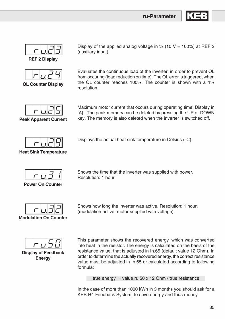
85
Power On Counter
Shows the time that the inverter was supplied with power.Resolution: 1 hour
ru-Parameter
Heat Sink Temperature
Displays the actual heat sink temperature in Celsius (°C).
OL Counter Display
Display of the applied analog voltage in % (10 V = 100%) at REF 2(auxiliary input).
Evaluates the continuous load of the inverter, in order to prevent OLfrom occuring (load reduction on time). The OL error is triggered, whenthe OL counter reaches 100%. The counter is shown with a 1%resolution.
Peak Apparent Current
Maximum motor current that occurs during operating time. Display in[A]. The peak memory can be deleted by pressing the UP or DOWNkey. The memory is also deleted when the inverter is switched off.
REF 2 Display
Modulation On Counter
Shows how long the inverter was active. Resolution: 1 hour.(modulation active, motor supplied with voltage).
Display of FeedbackEnergy
This parameter shows the recovered energy, which was convertedinto heat in the resistor. The energy is calculated on the basis of theresistance value, that is adjusted in In.65 (default value 12 Ohm). Inorder to determine the actually recovered energy, the correct resistancevalue must be adjusted in In.65 or calculated according to followingformula:
true energy = value ru.50 x 12 Ohm / true resistance
In the case of more than 1000 kWh in 3 months you should ask for aKEB R4 Feedback System, to save energy and thus money.
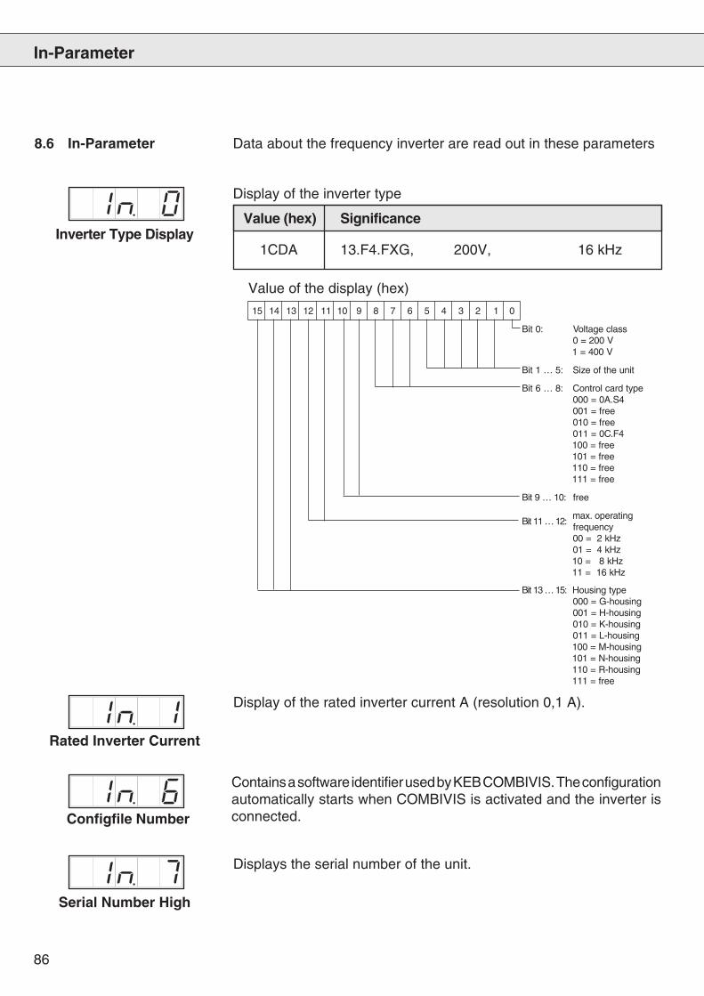
86
51 41 31 21 11 01 9 8 7 6 5 4 3 2 1 0
:0tiB ssalcegatloVV002=0V004=1
:5…1tiB tinuehtfoeziS
:8…6tiB epytdraclortnoC4S.A0=000
eerf=100eerf=010
4F.C0=110eerf=001eerf=101eerf=011eerf=111
:01…9tiB eerf
:21…11tiBgnitarepo.xam
ycneuqerfzHk2=00zHk4=10zHk8=01zHk61=11
:51…31tiB epytgnisuoHgnisuoh-G=000gnisuoh-H=100gnisuoh-K=010gnisuoh-L=110gnisuoh-M=001gnisuoh-N=101gnisuoh-R=011
eerf=111
8.6 In-Parameter
Inverter Type Display
Data about the frequency inverter are read out in these parameters
Display of the inverter type
Rated Inverter Current
Display of the rated inverter current A (resolution 0,1 A).
Configfile Number
Contains a software identifier used by KEB COMBIVIS. The configurationautomatically starts when COMBIVIS is activated and the inverter isconnected.
Serial Number High
Displays the serial number of the unit.
Value (hex) Significance
1CDA 13.F4.FXG, 200V, 16 kHz
Value of the display (hex)
In-Parameter
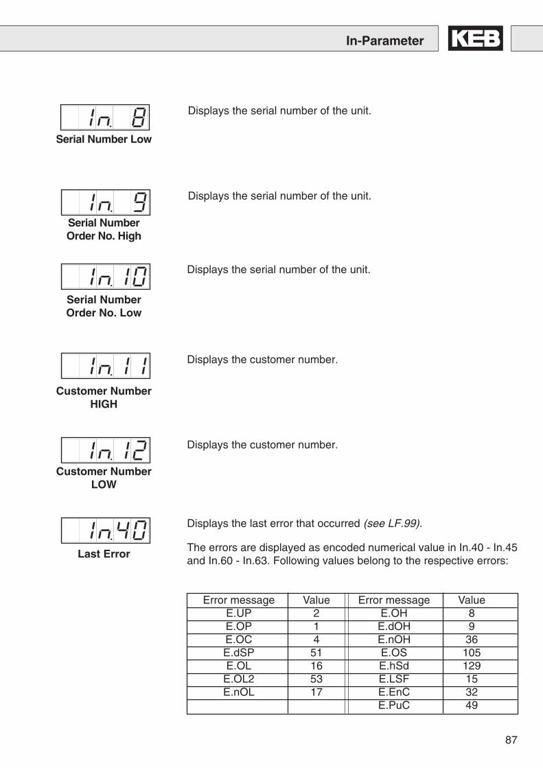
87
In-Parameter
Serial Number Low
Displays the serial number of the unit.
Serial NumberOrder No. High
Displays the serial number of the unit.
Serial NumberOrder No. Low
Displays the serial number of the unit.
Customer NumberHIGH
Displays the customer number.
Customer NumberLOW
Displays the customer number.
Last Error
Displays the last error that occurred (see LF.99).
The errors are displayed as encoded numerical value in In.40 - In.45and In.60 - In.63. Following values belong to the respective errors:
Error message Value Error message ValueE.UP 2 E.OH 8E.OP 1 E.dOH 9E.OC 4 E.nOH 36E.dSP 51 E.OS 105E.OL 16 E.hSd 129
E.OL2 53 E.LSF 15E.nOL 17 E.EnC 32
E.PuC 49
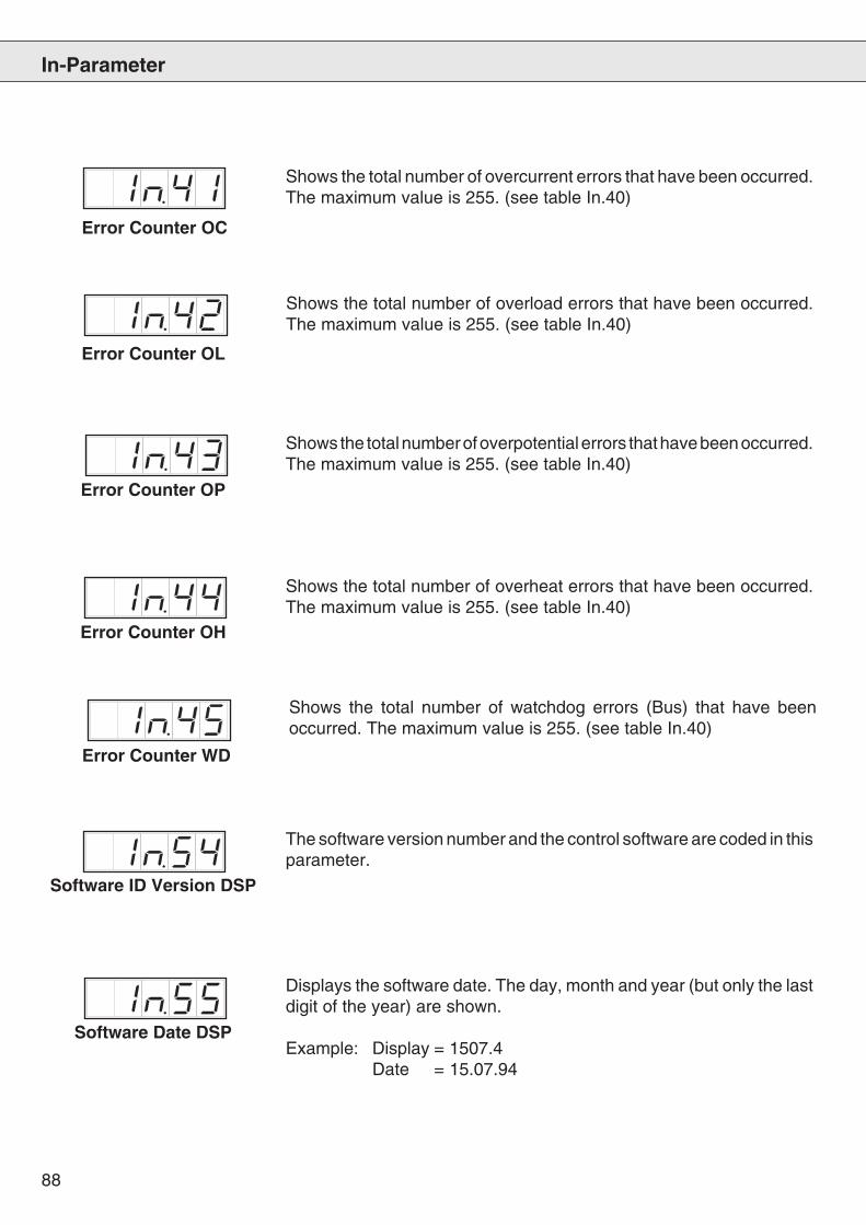
88
In-Parameter
Shows the total number of overload errors that have been occurred.The maximum value is 255. (see table In.40)
Error Counter OL
Error Counter OC
Shows the total number of overcurrent errors that have been occurred.The maximum value is 255. (see table In.40)
Error Counter WD
Shows the total number of watchdog errors (Bus) that have beenoccurred. The maximum value is 255. (see table In.40)
Software ID Version DSP
The software version number and the control software are coded in thisparameter.
Software Date DSP
Displays the software date. The day, month and year (but only the lastdigit of the year) are shown.
Example: Display = 1507.4Date = 15.07.94
Error Counter OH
Shows the total number of overheat errors that have been occurred.The maximum value is 255. (see table In.40)
Error Counter OP
Shows the total number of overpotential errors that have been occurred.The maximum value is 255. (see table In.40)
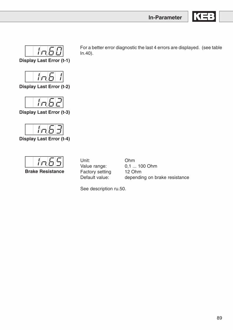
89
In-Parameter
Display Last Error (t-1)
Display Last Error (t-2)
Display Last Error (t-3)
Display Last Error (t-4)
Brake Resistance
For a better error diagnostic the last 4 errors are displayed. (see tableIn.40).
Unit: OhmValue range: 0,1 ... 100 OhmFactory setting 12 OhmDefault value: depending on brake resistance
See description ru.50.
90
Start-Up Instructions
9.1 Commissioning ofan AsynchronousMachine with Gearbox
9. Start-UpInstructions
The following procedure is recommended for the commissioning ofthe KEB COMBIVERT F4-F lift version 3.0 with asynchronous machineand gearbox:
Adjust the parameters in ascending sequence, as this initiates partialpresettings of the unit. Start with the lift data (LF-parameter). Savethe adjusted data by activating the „Enter key“.
LF.00: Enter password (440)LF.04: Check, if the value „0“ is adjustedLF.20: Enter system speed in m/sLF.21: Enter the diameter of the traction sheave in mm, if necessary,
remeasureLF.22: Enter gear reduction, if necessary, countLF.23: Enter rope suspension (1 for 1:1, 2 for 2:1 etc.)LF.24: Enter nominal load (lifting capacity) of the cabine in kgLF.30: Select control procedure (0=without feedback, 2=with
feedback)LF.40 to LF.45: Enter speed in m/s
dr.00: Enter rated motor power in kW (1 kW = 1.36 PS)dr.01: Enter rated motor speed (not synchronous speed)dr.02: Enter rated motor currentdr.03: Enter rated motor frequencydr.04: Enter cos phi of the motordr.12: Enter rated motor voltage (if the value to be adjusted is already
entered, it is essential to acknowledge the value with ENTER)
EC.01: Enter encoder pulse number
With inspection speed check, whether the lift moves. In case of errormessage „E.EnC“ execute an encoder track change with EC.2=1.Reset the error message through switch off and switch on.
In case of error message „E.OL2“ adjust LF.38=0 (8 kHz operatingfrequency).
In case of wrong travel direction (up and down exchanged) activatethe reversal of driving direction with LF.05=1.
If the cabine rolls back when releasing the brake, increase LF.33 insteps of 500.
91
Start-Up Instructions
9.2 Commissioning of aGearless PermanentMagnet Machine
The following procedure is recommended for the commissioning of aKEB COMBIVERT F4-F lift version 3.0 with a gearless permanentmagnet machine:
Adjust the parameters in ascending sequence, as this initiates partialpresettings of the unit. Start with the selection of the motor and theresolution and adjustment of the lift data (LF-parameter). Save theadjusted data by activating the „ENTER key“.
When using a synchronous machine with Hiperface-encoder (inverterpart no. xx.F4.Fxx-xi5x), the motor, encoder and control data areautomatically transferred from the encoder to the inverter at the firstswitch on. However, the encoder must be preset with the data. Pleaseinquire at your motor manufacturer, whether this has been done. Ifthe data is stored in the encoder, the entire „dr“ and „EC“-parametersas well as LF.30 - LF.36 need not to be entered in the inverter anymore.
LF.00: Enter password (440)LF.04: Adjust value “1”LF.06: Adjust value “1”
LF.20: Enter system speed in m/sLF.21: Enter the diameter of the traction sheave in mm, if necessary,
remeasureLF.22: Enter gear reduction = 1LF.23: Enter rope suspension (1 for 1:1, 2 for 2:1 etc.)LF.24: Enter nominal load (lifting capacity) of the cabine in kg
LF.31 to LF.33: Enter speed controller data (Use pracmatical valuesor inquire about adjustment at KEB.)
LF.40 to LF.45: Enter speeds in m/s
dr.01: Enter rated motor speeddr.02: Enter rated motor currentdr.03: Enter rated motor frequencydr.09: Enter rated motor torquedr.17: Enter EMK voltage constant (if only the rated motor voltage is
known, EMK can be calculated according to following formula:U
EMK = U
N / n
N x 1000 rpm)
dr.41: Enter winding resistancedr.42: Enter winding inductivity

92
EC.01: Enter encoder pulse number
EC.04: Execute a position alignment.In doing so make sure that the machine is unloaded, i.e. theropes may not rest upon the traction sheave.If the error „E.EnC“ or E.OS“ occurs during the alignment or ifthe alignment is not automatically completed, it must bechecked, if the motor cables UVW inverter correspond to UVWmotor.
LF.36: Check the maximum torque of the motor and, if necessary,adjust it.(Attention: If this parameter is adjusted too high for synchronousmachines and if the machine is permanently overloaded, it willlead to demagnetization of the permanent magnets and thedestruction of the motor!)
Check with inspection speed, if the lift moves. In case of error message„E.EnC“ or „E.OS“ check, if the motor cables UVW inverter correspondto UVW motor.
In case of error message “E.OL2” adjust LF.38=0 (8kHz operatingfrequency).
In case of wrong travel direction (up and down exchanged) activatethe reversal of driving direction with LF.05=1.
If the cabine rolls back when releasing the brake, increase LF.33 insteps of 500.
Start-UP Instructions
93
Start-Up Instructions
9.3 Commissioning of aG e a r l e s sA s y n c h r o n o u sMachine with SinCos-Encoder
The following procedure is recommended for the commissioning ofthe KEB COMBIVERT F4-F lift version 3.0 with a gearlessasynchronous machine with SinCos-encoder:
Adjust the parameters in ascending sequence, as this initiates partialpresettings of the unit. Start with the selection of the resolution andthe adjustment of the lift data (LF-parameter). Save the adjusted databy activating the „ENTER key.
LF.00: Enter password (440)LF.04: Check, if value „0“ is adjustedEC.06: Adjust value „1“LF.06: Adjust value „1“
LF.20: Enter system speed in m/sLF.21: Enter diameter of traction sheave in mm, if necessary,
remeasureLF.22: Enter gear reduction = 1LF.23: Enter rope suspension (1 for 1:1, 2 for 2:1 etc.)LF.24: Enter nominal load (lifting capacity) of the cabine in kg
LF.30: Select control procedure (0=without feedback, 2=withfeedback)
LF.31 to LF.33: Enter speed controller data (use pracmatical valuesor inquire about adjustment at KEB)
LF.40 to LF.45: Enter speeds in m/s
LF.54: Due to the high mass moment of inertia, adjust the stoppingjerk as small as possible(ca. 0,3m/s3)
dr.00: Enter rated motor power in kW (1 kW = 1.36 PS)dr.01: Enter rated motor speed (not synchronous speed)dr.02: Enter rated motor currentdr.03: Enter rated motor frequencydr.04: Enter cos phi of the motordr.12: Enter rated motor voltage (if the value to be adjusted is already
entered, it is essential to acknowledge the value with ENTER)
EC.01: Enter encoder pulse number
94
LF.36: Check the maximum torque of the motor and, if necessary,adjust it.
Check with inspection speed, if the lift moves. In case of error message„E.EnC“ execute an encoder track change with EC.2=1. After that theinverter may indicate „E.OS“. Reset the error message through switchoff and switch on.
In case of error message „E.OL2“ adjust LF.38=0 (8kHz operatingfrequency).
In case of wrong travel direction (up and down exchanged), activatereversal of driving direction with LF.05=1.
If the cabine rolls back when releasing the brake, increase LF.33 insteps of 500.
Start-Up Instructions
95
Start-Up Instructions
9.4 Commissioning of aPermanent MagnetMachine with Gearbox
The following procedure is recommended for the commissioning ofthe KEB COMBIVERT F4-F lift version 3.0 with permanent magnetmachine and gearbox:
Adjust the parameters in ascending sequence, as this initiates partialpresettings of the unit. Start with the selection of the motor and theresolution and adjustment of the lift data (LF-parameter). Save theadjusted data by activating the „Enter key“.
LF.00: Enter password (440)LF.04: Adjust value „1“
LF.20: Enter system speed in m/sLF.21: Enter diameter of the traction sheave, if necessary, remeasureLF.22: Enter gear reduction, if necessary, countLF.23: Enter rope suspension (1 for 1:1, 2 for 2:1 etc.)LF.24: Enter additional load (lifting capacity, payload) of the cabine in
kg
LF.31 to LF.33: Enter speed controller data (use pracmatical valuesor inquire about adjustment at KEB)
LF.40 to LF.45: Enter speeds in ms
dr.01: Enter rated motor speeddr.02: Enter rated motor currentdr.03: Enter rated motor frequencydr.09: Enter rated motor torquedr.17: Enter EMK voltage constant (if only the motor voltage is known,
EMK can be calculated according to following formula: UEMK
=UN / nN x 1000 rpm)
dr.41: Enter winding resistancedr.42: Enter winding inductivity
EC.01: Enter encoder pulse number
EC.04: Execute a position alignment. In doing so make sure that themachine is unloaded, i.e. the ropes may not rest upon theleading sheave. If the error „E.EnC“ or E.OS“ occurs duringthe alignment or if the alignment is not automatically completed,it must be checked, if the motor cables UVW invertercorrespond to UVW motor.
LF.36: Check the maximum torque of the motor and, if necessary,adjust it. (Attention: If this parameter is adjusted too high forsynchronous machines and if the machine is permanentlyoverloaded, it will lead to demagnetization of the permanentmagnets and the destruction of the motor!)
96
Start-Up Instructions
9.5 A d j u s t m e n tAssistance forConventional Lift Mo-tors (AsynchronousMachine)
Check with inspection speed, if the lift moves. In case of error message„E.EnC“ or „E.OS“ check, if the motor cables UVW inverter correspondto UVW motor.
In case of error message „E.OL2“ adjust LF.38=0 (8kHz operatingfrequency).
In case of wrong travel direction (up and down exchanged), activatereversal of driving direction with LF.05=1.
If the cabine rolls back when releasing the brake, increase LF.33 insteps of 500.
The inverter KEB COMBIVERT F4-F Lift is well suited for modern lift/industrial motors and conventional lift motors and thus equally suitedfor modernization.
Unlike modern lift motors and industrial motors, conventional and oldlift motors have a ‘soft’ torque-speed-characteristic. This can be seenin the rated speeds. Typical for modern machines are 1450 rpm (with4-pole motors) and with conventional motors 1380 rpm or 880 rpm (6-pole machines).
Often the specifications on the name plate are inadequate or non-existant. In this case the motor data must be adjusted on-site for thesystem.
If the lift does not reach the rated speed during ‘empty-downward-drive’(display LF.90), do the following:
1.) Decrease field weakening speed (dr.19) to approx. 2/3 of thesynchronous speed (approx. 1000 rpm with 4-pole motors; approx.680 rpm with 6-pole motors).
2.) Set cos phi (dr.04) to 0,9
3.) Decrease rated motor speed dr.01 in steps of 20 until the ratedspeed is reached during a downward drive.
When the power consumption of the motor is too high (display in ru.02or LF.87) it helps to increase dr.01 in steps of 10. At the same timecheck, if the ‘empty-downward-drive’ can still be driven with ratedspeed.
If possible remove hand wheels with big inertia. If that is not possible,then the starting jerk (LF.50) and acceleration (LF.51) should be as lowas possible (both values approx. 0.4), so that the motor is notoverstressed.

97
Supplement
10.1 New Functions withVersion 3.0
• New parameter group „dr“ for motor dataThe existing parameters LF.10 – LF.16, LF.91 and LF.A0 – LF.A8 inV1.4 have been combined and extended in this new parametergroup and are displayed, depending on the selected machine type(see dr-parameters).
• New parameter group „EC“ for encoder dataThe existing parameters LF.03, LF.17, LF.18 and LF.b0 – LF.b5 inV1.4 have been combined and extended in this new parametergroup (see EC-parameters).
• New parameter group „An“ for the adjustment of analog signals.This new parameter group makes it possible to better adjust theanalog inputs and outputs of the inverter to the external conditions(see An-parameters).
• New function of high-resolution of speed for slow-rotating motors(see parameter LF.06).
• New function separate acceleration curve for the safety gear release(see parameter LF.55 and LF.56)
• New function speed deviation detection(see parameter LF.57 – LF.59)
10. Annex
U V W X2.23 X3.10 X2.11 X3.11 X2.1 X3.21 X3.20
24V 0V
K12
24V
24V 0V
K11
K11
K11
K1
K2
K12
N
M
PE
3 ~
L
10.2 Control Instructions
InverterSafety circuit
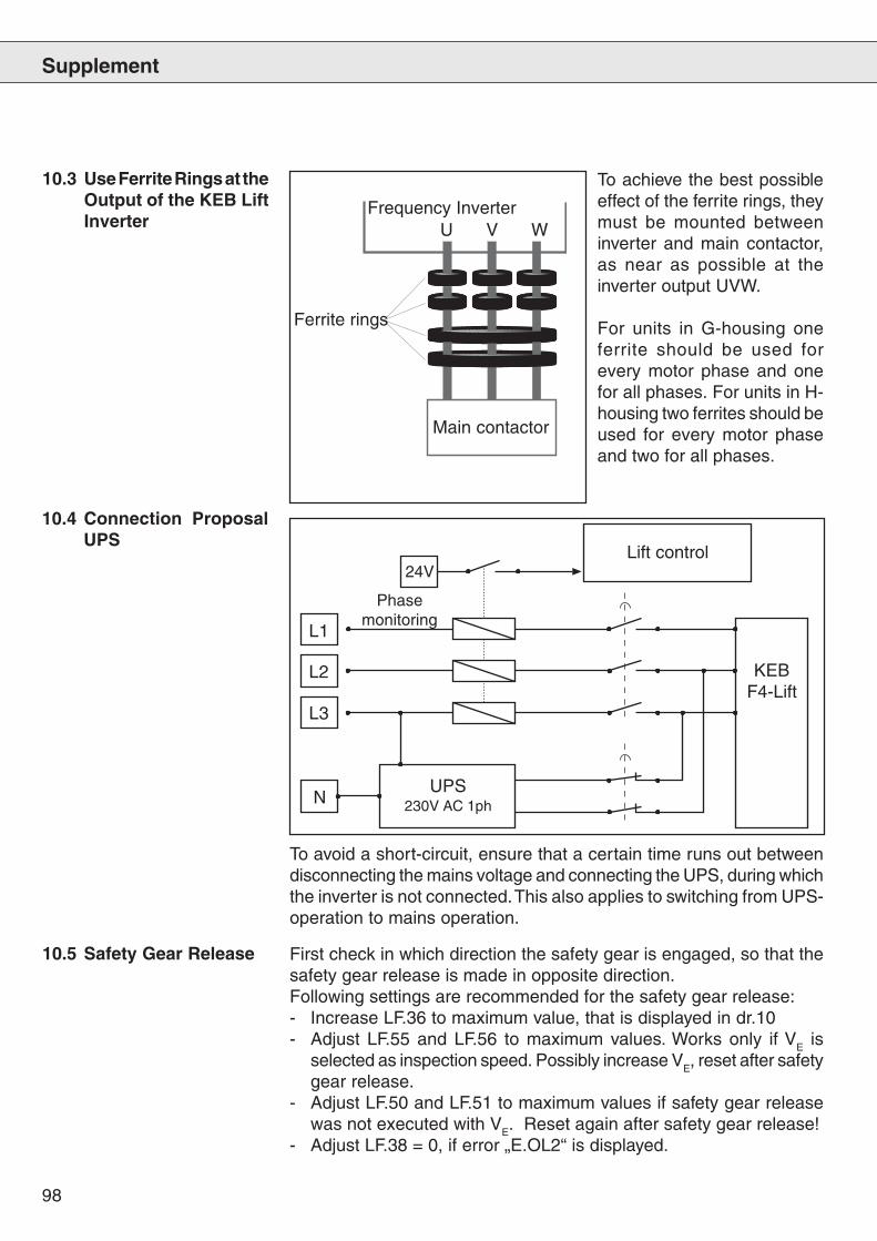
98
Supplement
10.3 Use Ferrite Rings at theOutput of the KEB LiftInverter U V W
Main contactor
Frequency Inverter
Ferrite rings
To achieve the best possibleeffect of the ferrite rings, theymust be mounted betweeninverter and main contactor,as near as possible at theinverter output UVW.
For units in G-housing oneferrite should be used forevery motor phase and onefor all phases. For units in H-housing two ferrites should beused for every motor phaseand two for all phases.
10.4 Connection ProposalUPS
To avoid a short-circuit, ensure that a certain time runs out betweendisconnecting the mains voltage and connecting the UPS, during whichthe inverter is not connected. This also applies to switching from UPS-operation to mains operation.
Lift control
KEBF4-Lift
24V
Phasemonitoring
L1
L2
L3
NUPS
230V AC 1ph
10.5 Safety Gear Release First check in which direction the safety gear is engaged, so that thesafety gear release is made in opposite direction.Following settings are recommended for the safety gear release:- Increase LF.36 to maximum value, that is displayed in dr.10- Adjust LF.55 and LF.56 to maximum values. Works only if VE is
selected as inspection speed. Possibly increase VE, reset after safetygear release.
- Adjust LF.50 and LF.51 to maximum values if safety gear releasewas not executed with VE. Reset again after safety gear release!
- Adjust LF.38 = 0, if error „E.OL2“ is displayed.

99
Supplement
10.6 Parameter Lists
10.6.1 LF-Parameter
‘1 LF.06 = 1 high-resolution on‘2 LF.04 = 1 SSM
Gr. No. Name Address P E R Resol. Lower Limit Upper Limit Default Value UnitLF 00 Password 3500 E 1 0 9999 -4 ---LF 01 User-defined password 3501 E 1 0 9999 440 ---LF 02 Steering / operating mode 3502 E 1 1 4 1 ---LF 04 ASM/SSM-selection 3504 E 1 0:ASM 1:SSM 0:ASM ---LF 05 Reversal of travel direction 3505 1 0:off 1:on 0:off ---LF 06 High-resolution 3506 E 1 0:off 1:on 0:off ---LF 19 DC voltage compensation 3513 E 1 150 501:off 400 VLF 20 Rated system speed 3514 0,001 0,000 15,000 0 m/sLF 21 Traction sheave diameter 3515 1 200 2000 600 mmLF 22 Gear reduction ratio 3516 0,01 1,00 99,99 30 ---LF 23 Catenary suspension 3517 1 1 8 1 ---LF 24 Load 3518 1 0 65535 0 kgLF 25 Torque increase of the door drive 3519 0,1 0,0 25,5 6 %LF 26 Rated speed of the door drive 351A 1 100 6000 1440 rpmLF 27 Rated frequency of the door drive 351B 1 20 100 50 HzLF 28 Rated voltage of the door drive 351C 1 1 650 400 VLF 30 Control method 351E E 1 0 3 0 ---LF 31 KP speed 351F 1 1 65535 3000 ---LF 32 KI speed 3520 1 0 65535 1000 ---LF 33 KI speed offset 3521 1 0 65535 1000 ---LF 34 KP current 3522 1 1 65535 1500 ---LF 35 KI current 3523 1 0 65535 500 ---LF 36 Maximum torque 3524 0,1 0 dr.10 2 * dr.9
1'1 1,5*dr.9 '2 NmLF 37 Torque increase 3525 0,1 0,0 25,2 10 %LF 38 Operating frequency change 3526 1 0 1 1 ---LF 40 Set value VB, correction speed 3528 0,001 0,000 0,300 0 m/sLF 41 Set value VE, crawl speed 3529 0,001 0,000 0,300 0 m/sLF 42 Set value VN, rated speed 352A 0,001 0,000 LF.20 0 m/sLF 43 Set value VI, inspection speed 352B 0,001 0,000 0,630 0 m/sLF 44 Set value V1, intermediate speed 1 352C 0,001 0,000 LF.20 0 m/sLF 45 Set value V2, intermediate speed 2 352D 0,001 0,000 LF.20 0 m/sLF 46 Set speed of door drive 352E 0,5 0 16000 0 rpm
0,1 '1 2000 '1LF 50 Starting jerk 3532 0,01 0,10 9,99 0,60 m/s^3LF 51 Acceleration 3533 0,01 0,10 2,00 0,90 m/s^2LF 52 Deceleration jerk 3534 0,01 0,10 9,99 1,00 m/s^3LF 53 Deceleration 3535 0,01 0,10 2,00 0,60 m/s^2LF 54 Stopping jerk 3536 0,01 0,01:off 9,99 0,01:off m/s^3LF 55 Starting jerk VE (crawl speed) 3537 0,01 0,10 9,99 0,60 m/s^3LF 56 Acceleration VE (crawl speed) 3538 0,01 0,10 2,00 0,90 m/s^2LF 57 Speed Deviation mode 3539 1 0 2 1 ---LF 58 Speed deviation level 353A 1 0 30 10 %LF 59 Speed diviation - release time 353B 0,001 0,000 10,000 3,000 sLF 60 Switching level brake disconnection 353C 0,001 0,000 0,010 0,005 m/sLF 61 Monitoring overspeed 353D 0,001 0,000 18,000 1,1 * LF.42 m/sLF 62 Deceleration check level 353E 0,001 0,000 15,000 0,95 * LF.42 m/sLF 63 Running open door level 353F 0,001 0,000 0,300 0,250 m/s
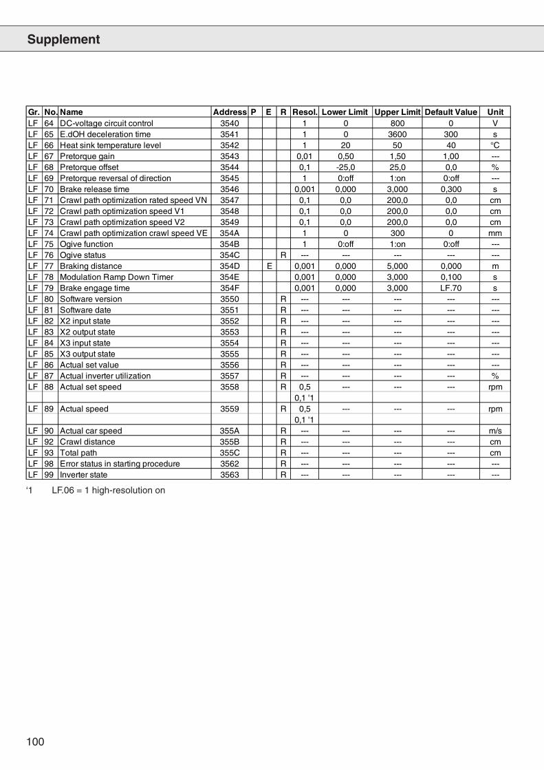
100
Supplement
‘1 LF.06 = 1 high-resolution on
Gr. No. Name Address P E R Resol. Lower Limit Upper Limit Default Value UnitLF 64 DC-voltage circuit control 3540 1 0 800 0 VLF 65 E.dOH deceleration time 3541 1 0 3600 300 sLF 66 Heat sink temperature level 3542 1 20 50 40 °CLF 67 Pretorque gain 3543 0,01 0,50 1,50 1,00 ---LF 68 Pretorque offset 3544 0,1 -25,0 25,0 0,0 %LF 69 Pretorque reversal of direction 3545 1 0:off 1:on 0:off ---LF 70 Brake release time 3546 0,001 0,000 3,000 0,300 sLF 71 Crawl path optimization rated speed VN 3547 0,1 0,0 200,0 0,0 cmLF 72 Crawl path optimization speed V1 3548 0,1 0,0 200,0 0,0 cmLF 73 Crawl path optimization speed V2 3549 0,1 0,0 200,0 0,0 cmLF 74 Crawl path optimization crawl speed VE 354A 1 0 300 0 mmLF 75 Ogive function 354B 1 0:off 1:on 0:off ---LF 76 Ogive status 354C R --- --- --- --- ---LF 77 Braking distance 354D E 0,001 0,000 5,000 0,000 mLF 78 Modulation Ramp Down Timer 354E 0,001 0,000 3,000 0,100 sLF 79 Brake engage time 354F 0,001 0,000 3,000 LF.70 sLF 80 Software version 3550 R --- --- --- --- ---LF 81 Software date 3551 R --- --- --- --- ---LF 82 X2 input state 3552 R --- --- --- --- ---LF 83 X2 output state 3553 R --- --- --- --- ---LF 84 X3 input state 3554 R --- --- --- --- ---LF 85 X3 output state 3555 R --- --- --- --- ---LF 86 Actual set value 3556 R --- --- --- --- ---LF 87 Actual inverter utilization 3557 R --- --- --- --- %LF 88 Actual set speed 3558 R 0,5 --- --- --- rpm
0,1 '1LF 89 Actual speed 3559 R 0,5 --- --- --- rpm
0,1 '1LF 90 Actual car speed 355A R --- --- --- --- m/sLF 92 Crawl distance 355B R --- --- --- --- cmLF 93 Total path 355C R --- --- --- --- cmLF 98 Error status in starting procedure 3562 R --- --- --- --- ---LF 99 Inverter state 3563 R --- --- --- --- ---
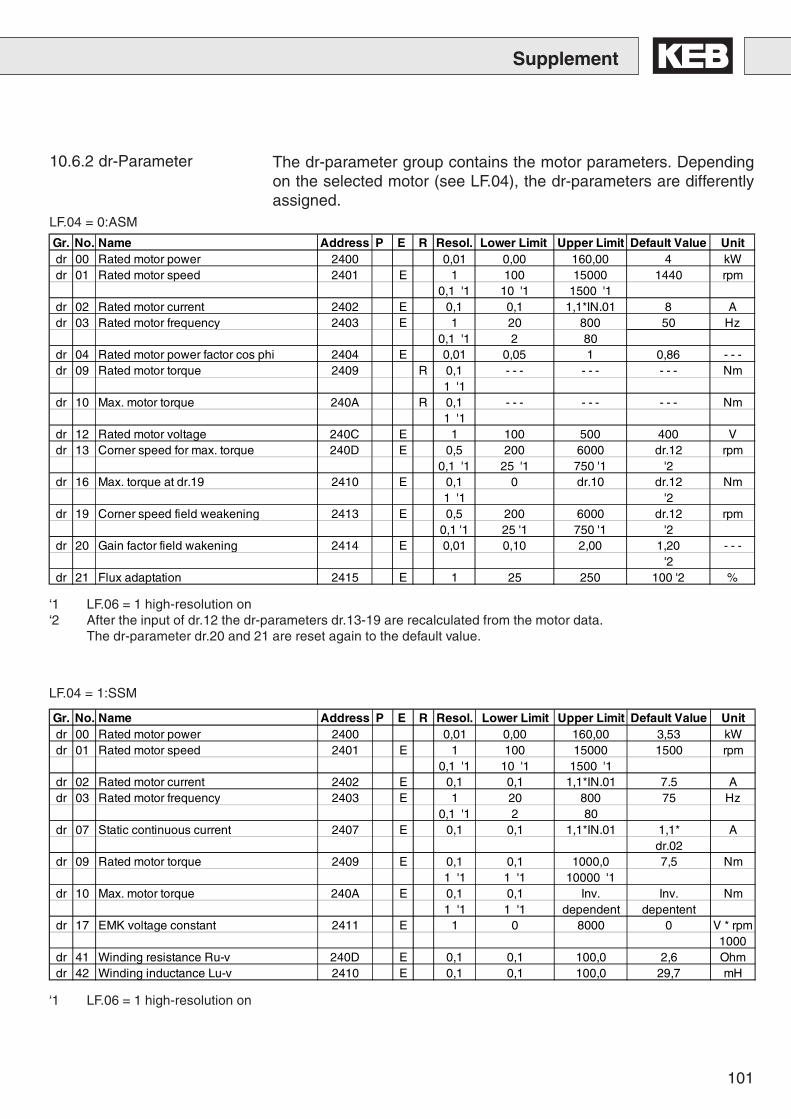
101
Supplement
10.6.2 dr-Parameter The dr-parameter group contains the motor parameters. Dependingon the selected motor (see LF.04), the dr-parameters are differentlyassigned.
‘1 LF.06 = 1 high-resolution on‘2 After the input of dr.12 the dr-parameters dr.13-19 are recalculated from the motor data.
The dr-parameter dr.20 and 21 are reset again to the default value.
LF.04 = 0:ASM
LF.04 = 1:SSM
‘1 LF.06 = 1 high-resolution on
Gr. No. Name Address P E R Resol. Lower Limit Upper Limit Default Value Unitdr 00 Rated motor power 2400 0,01 0,00 160,00 4 kWdr 01 Rated motor speed 2401 E 1 100 15000 1440 rpm
0,1 '1 10 '1 1500 '1dr 02 Rated motor current 2402 E 0,1 0,1 1,1*IN.01 8 Adr 03 Rated motor frequency 2403 E 1 20 800 50 Hz
0,1 '1 2 80dr 04 Rated motor power factor cos phi 2404 E 0,01 0,05 1 0,86 - - -dr 09 Rated motor torque 2409 R 0,1 - - - - - - - - - Nm
1 '1dr 10 Max. motor torque 240A R 0,1 - - - - - - - - - Nm
1 '1dr 12 Rated motor voltage 240C E 1 100 500 400 Vdr 13 Corner speed for max. torque 240D E 0,5 200 6000 dr.12 rpm
0,1 '1 25 '1 750 '1 '2dr 16 Max. torque at dr.19 2410 E 0,1 0 dr.10 dr.12 Nm
1 '1 '2dr 19 Corner speed field weakening 2413 E 0,5 200 6000 dr.12 rpm
0,1 '1 25 '1 750 '1 '2dr 20 Gain factor field wakening 2414 E 0,01 0,10 2,00 1,20 - - -
'2dr 21 Flux adaptation 2415 E 1 25 250 100 '2 %
Gr. No. Name Address P E R Resol. Lower Limit Upper Limit Default Value Unitdr 00 Rated motor power 2400 0,01 0,00 160,00 3,53 kWdr 01 Rated motor speed 2401 E 1 100 15000 1500 rpm
0,1 '1 10 '1 1500 '1dr 02 Rated motor current 2402 E 0,1 0,1 1,1*IN.01 7.5 Adr 03 Rated motor frequency 2403 E 1 20 800 75 Hz
0,1 '1 2 80dr 07 Static continuous current 2407 E 0,1 0,1 1,1*IN.01 1,1* A
dr.02dr 09 Rated motor torque 2409 E 0,1 0,1 1000,0 7,5 Nm
1 '1 1 '1 10000 '1dr 10 Max. motor torque 240A E 0,1 0,1 Inv. Inv. Nm
1 '1 1 '1 dependent depententdr 17 EMK voltage constant 2411 E 1 0 8000 0 V * rpm
1000dr 41 Winding resistance Ru-v 240D E 0,1 0,1 100,0 2,6 Ohmdr 42 Winding inductance Lu-v 2410 E 0,1 0,1 100,0 29,7 mH
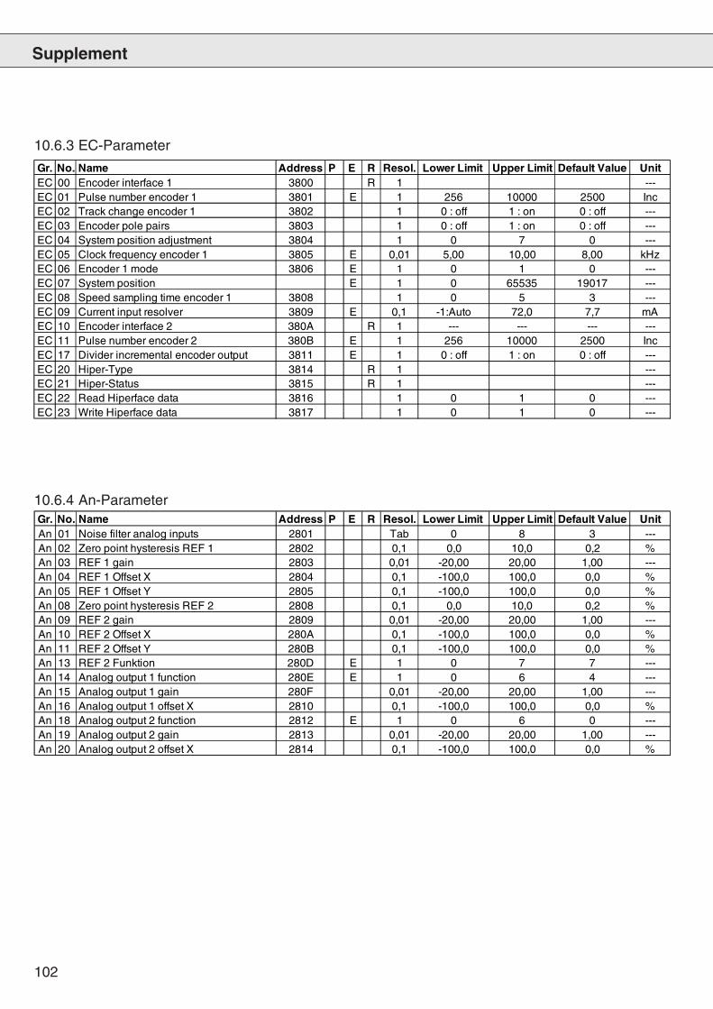
102
Supplement
10.6.3 EC-Parameter
10.6.4 An-Parameter
Gr. No. Name Address P E R Resol. Lower Limit Upper Limit Default Value UnitEC 00 Encoder interface 1 3800 R 1 ---EC 01 Pulse number encoder 1 3801 E 1 256 10000 2500 IncEC 02 Track change encoder 1 3802 1 0 : off 1 : on 0 : off ---EC 03 Encoder pole pairs 3803 1 0 : off 1 : on 0 : off ---EC 04 System position adjustment 3804 1 0 7 0 ---EC 05 Clock frequency encoder 1 3805 E 0,01 5,00 10,00 8,00 kHzEC 06 Encoder 1 mode 3806 E 1 0 1 0 ---EC 07 System position E 1 0 65535 19017 ---EC 08 Speed sampling time encoder 1 3808 1 0 5 3 ---EC 09 Current input resolver 3809 E 0,1 -1:Auto 72,0 7,7 mAEC 10 Encoder interface 2 380A R 1 --- --- --- ---EC 11 Pulse number encoder 2 380B E 1 256 10000 2500 IncEC 17 Divider incremental encoder output 3811 E 1 0 : off 1 : on 0 : off ---EC 20 Hiper-Type 3814 R 1 ---EC 21 Hiper-Status 3815 R 1 ---EC 22 Read Hiperface data 3816 1 0 1 0 ---EC 23 Write Hiperface data 3817 1 0 1 0 ---
Gr. No. Name Address P E R Resol. Lower Limit Upper Limit Default Value UnitAn 01 Noise filter analog inputs 2801 Tab 0 8 3 ---An 02 Zero point hysteresis REF 1 2802 0,1 0,0 10,0 0,2 %An 03 REF 1 gain 2803 0,01 -20,00 20,00 1,00 ---An 04 REF 1 Offset X 2804 0,1 -100,0 100,0 0,0 %An 05 REF 1 Offset Y 2805 0,1 -100,0 100,0 0,0 %An 08 Zero point hysteresis REF 2 2808 0,1 0,0 10,0 0,2 %An 09 REF 2 gain 2809 0,01 -20,00 20,00 1,00 ---An 10 REF 2 Offset X 280A 0,1 -100,0 100,0 0,0 %An 11 REF 2 Offset Y 280B 0,1 -100,0 100,0 0,0 %An 13 REF 2 Funktion 280D E 1 0 7 7 ---An 14 Analog output 1 function 280E E 1 0 6 4 ---An 15 Analog output 1 gain 280F 0,01 -20,00 20,00 1,00 ---An 16 Analog output 1 offset X 2810 0,1 -100,0 100,0 0,0 %An 18 Analog output 2 function 2812 E 1 0 6 0 ---An 19 Analog output 2 gain 2813 0,01 -20,00 20,00 1,00 ---An 20 Analog output 2 offset X 2814 0,1 -100,0 100,0 0,0 %
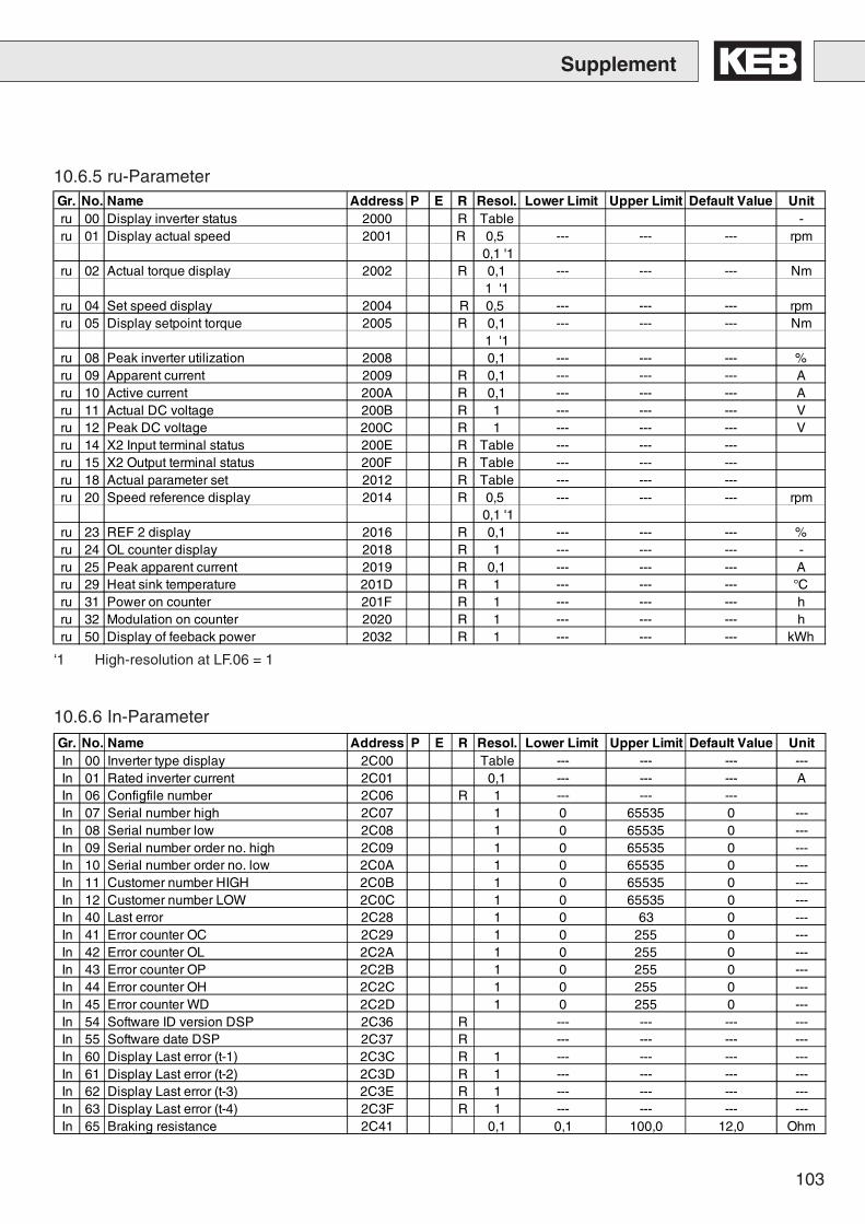
103
10.6.5 ru-Parameter
Supplement
‘1 High-resolution at LF.06 = 1
10.6.6 In-Parameter
Gr. No. Name Address P E R Resol. Lower Limit Upper Limit Default Value Unitru 00 Display inverter status 2000 R Table -ru 01 Display actual speed 2001 R 0,5 --- --- --- rpm
0,1 '1ru 02 Actual torque display 2002 R 0,1 --- --- --- Nm
1 '1ru 04 Set speed display 2004 R 0,5 --- --- --- rpmru 05 Display setpoint torque 2005 R 0,1 --- --- --- Nm
1 '1ru 08 Peak inverter utilization 2008 0,1 --- --- --- %ru 09 Apparent current 2009 R 0,1 --- --- --- Aru 10 Active current 200A R 0,1 --- --- --- Aru 11 Actual DC voltage 200B R 1 --- --- --- Vru 12 Peak DC voltage 200C R 1 --- --- --- Vru 14 X2 Input terminal status 200E R Table --- --- ---ru 15 X2 Output terminal status 200F R Table --- --- ---ru 18 Actual parameter set 2012 R Table --- --- ---ru 20 Speed reference display 2014 R 0,5 --- --- --- rpm
0,1 '1ru 23 REF 2 display 2016 R 0,1 --- --- --- %ru 24 OL counter display 2018 R 1 --- --- --- -ru 25 Peak apparent current 2019 R 0,1 --- --- --- Aru 29 Heat sink temperature 201D R 1 --- --- --- °Cru 31 Power on counter 201F R 1 --- --- --- hru 32 Modulation on counter 2020 R 1 --- --- --- hru 50 Display of feeback power 2032 R 1 --- --- --- kWh
Gr. No. Name Address P E R Resol. Lower Limit Upper Limit Default Value UnitIn 00 Inverter type display 2C00 Table --- --- --- ---In 01 Rated inverter current 2C01 0,1 --- --- --- AIn 06 Configfile number 2C06 R 1 --- --- ---In 07 Serial number high 2C07 1 0 65535 0 ---In 08 Serial number low 2C08 1 0 65535 0 ---In 09 Serial number order no. high 2C09 1 0 65535 0 ---In 10 Serial number order no. low 2C0A 1 0 65535 0 ---In 11 Customer number HIGH 2C0B 1 0 65535 0 ---In 12 Customer number LOW 2C0C 1 0 65535 0 ---In 40 Last error 2C28 1 0 63 0 ---In 41 Error counter OC 2C29 1 0 255 0 ---In 42 Error counter OL 2C2A 1 0 255 0 ---In 43 Error counter OP 2C2B 1 0 255 0 ---In 44 Error counter OH 2C2C 1 0 255 0 ---In 45 Error counter WD 2C2D 1 0 255 0 ---In 54 Software ID version DSP 2C36 R --- --- --- ---In 55 Software date DSP 2C37 R --- --- --- ---In 60 Display Last error (t-1) 2C3C R 1 --- --- --- ---In 61 Display Last error (t-2) 2C3D R 1 --- --- --- ---In 62 Display Last error (t-3) 2C3E R 1 --- --- --- ---In 63 Display Last error (t-4) 2C3F R 1 --- --- --- ---In 65 Braking resistance 2C41 0,1 0,1 100,0 12,0 Ohm
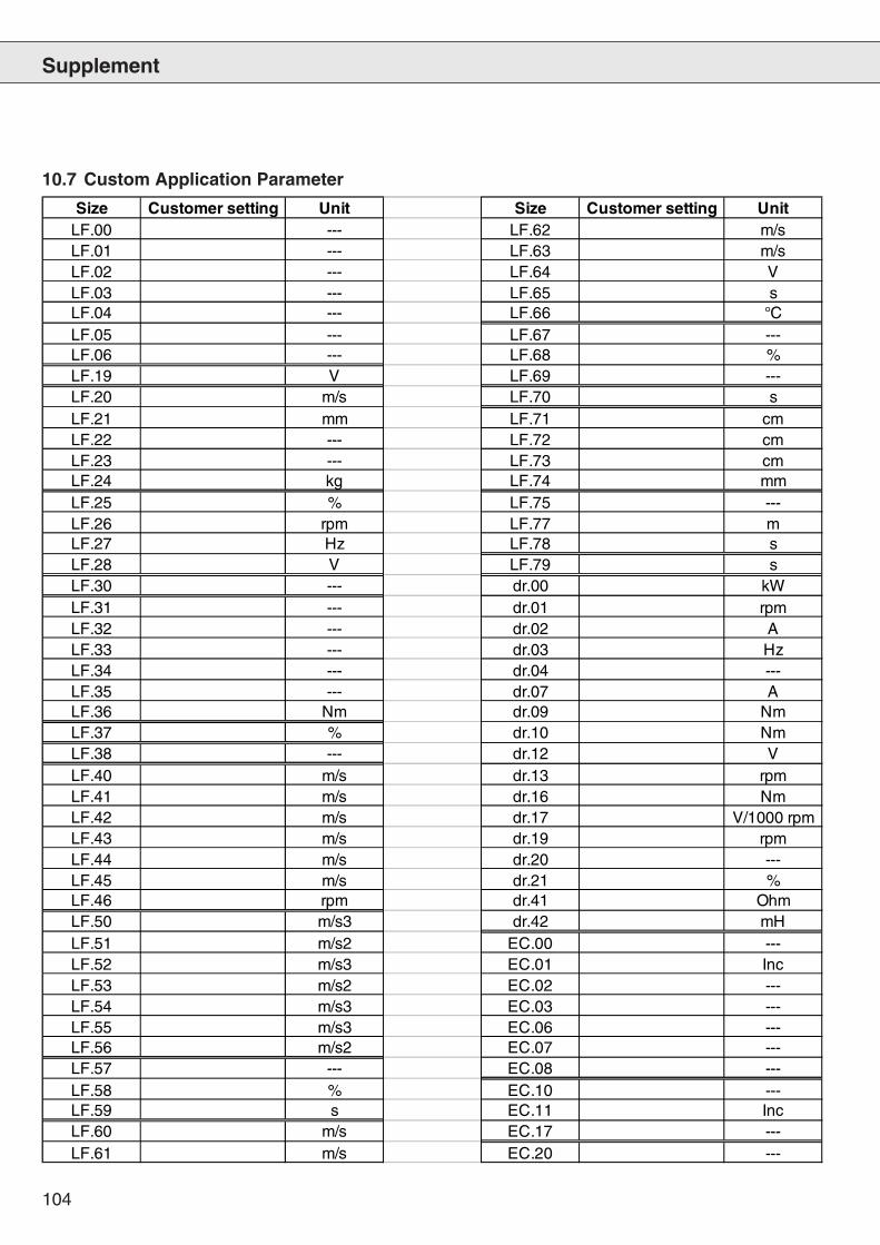
104
Supplement
10.7 Custom Application Parameter
Size Customer setting Unit Size Customer setting UnitLF.00 --- LF.62 m/sLF.01 --- LF.63 m/sLF.02 --- LF.64 VLF.03 --- LF.65 sLF.04 --- LF.66 °CLF.05 --- LF.67 ---LF.06 --- LF.68 %LF.19 V LF.69 ---LF.20 m/s LF.70 sLF.21 mm LF.71 cmLF.22 --- LF.72 cmLF.23 --- LF.73 cmLF.24 kg LF.74 mmLF.25 % LF.75 ---LF.26 rpm LF.77 mLF.27 Hz LF.78 sLF.28 V LF.79 sLF.30 --- dr.00 kWLF.31 --- dr.01 rpmLF.32 --- dr.02 ALF.33 --- dr.03 HzLF.34 --- dr.04 ---LF.35 --- dr.07 ALF.36 Nm dr.09 NmLF.37 % dr.10 NmLF.38 --- dr.12 VLF.40 m/s dr.13 rpmLF.41 m/s dr.16 NmLF.42 m/s dr.17 V/1000 rpmLF.43 m/s dr.19 rpmLF.44 m/s dr.20 ---LF.45 m/s dr.21 %LF.46 rpm dr.41 OhmLF.50 m/s3 dr.42 mHLF.51 m/s2 EC.00 ---LF.52 m/s3 EC.01 IncLF.53 m/s2 EC.02 ---LF.54 m/s3 EC.03 ---LF.55 m/s3 EC.06 ---LF.56 m/s2 EC.07 ---LF.57 --- EC.08 ---LF.58 % EC.10 ---LF.59 s EC.11 IncLF.60 m/s EC.17 ---LF.61 m/s EC.20 ---


© K
EB
00
.F4.
LEB
-K30
0 1
/200
4
Karl E. Brinkmann GmbHFörsterweg 36-38 • D-32683 Barntrup
fon: +49 5263 401-0 • fax: +49 5263 401-116net: www.keb.de • mail: [email protected]
KEB Antriebstechnik GmbH & Co. KGWildbacher Str. 5 • D–08289 Schneebergfon: +49 3772 67-0 • fax: +49 3772 67-281
mail: [email protected]
KEB Antriebstechnik Austria GmbHRitzstraße 8 • A-4614 Marchtrenk
fon: +43 7243 53586-0 • fax: +43 7243 53586-21Kostelni 32/1226 • CZ-370 04 Ceské Budejovicefon: +420 38 7319223 • fax: +420 38 7330697
mail: [email protected]
KEB AntriebstechnikHerenveld 2 • B-9500 Geraadsbergen
fon: +32 5443 7860 • fax: +32 5443 7898mail: [email protected]
KEB ChinaXianxia Road 299 • CHN-200051 Shanghai
fon: +86 21 62350922 • fax: +86 21 62350015net: www.keb-cn.com • mail: [email protected]
Société Française KEBZ.I. de la Croix St. Nicolas • 14, rue Gustave Eiffel
F-94510 LA QUEUE EN BRIEfon: +33 1 49620101 • fax: +33 1 45767495
mail: [email protected]
KEB (UK) Ltd.6 Chieftain Buisiness Park, Morris Close
Park Farm, Wellingborough GB-Northants, NN8 6 XFfon: +44 1933 402220 • fax: +44 1933 400724
net: www.keb-uk.co.uk • mail: [email protected]
KEB Italia S.r.l.Via Newton, 2 • I-20019 Settimo Milanese (Milano)
fon: +39 02 33500782 • fax: +39 02 33500790net: www.keb.it • mail: [email protected]
KEB - YAMAKYU Ltd.15–16, 2–Chome, Takanawa Minato-ku
J–Tokyo 108-0074fon: +81 33 445-8515 • fax: +81 33 445-8215
mail: [email protected]
KEB AntriebstechnikLeidsevaart 126 • NL–2013 HD Haarlem
fon: +31 23 5320049 • fax: +31 23 5322260mobil: +31 653964667
mail: [email protected]
KEB PortugalLugar de Salgueiros – Pavilhao A, Mouquim
P-4760 V. N. de Famalicaofon: +351 252 371318 • fax: +351 252 371320
mail: [email protected]
KEB Taiwan Ltd.1F, No.19-5, Shi Chou Rd., Tounan Town
R.O.C.-Yin-Lin Hsian / Taiwanfon: +886 5 5964242 • fax: +886 5 5964240
mail: [email protected]
KEB SverigeBox 265, Bergavägen 19
S-430 93 Hälsöfon: +46 31 961520 • fax: +46 31 961935
mail: [email protected]
KEBCO Inc.1335 Mendota Heights Road
USA-Mendota Heights, MN 55120fon: +1 651 4546162 • fax: +1 651 4546198
net: www.kebco.com • mail: [email protected]