Embed Size (px)
Citation preview
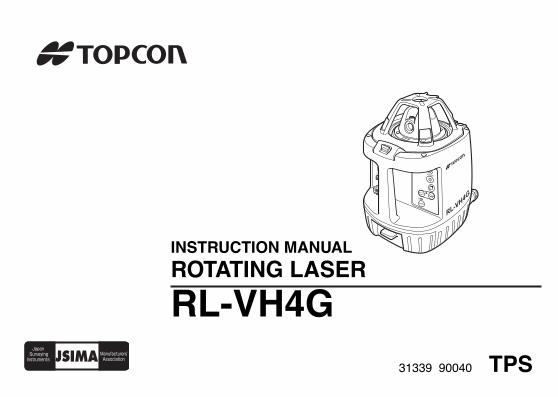
INSTRUCTION MANUAL
ROTATING LASER
RL-VH4G
31339 90040 TPS
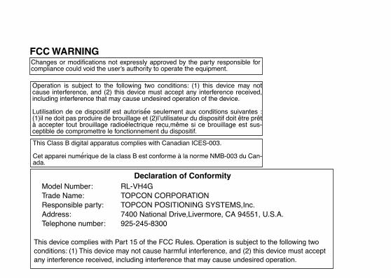
Changes or modifications not expressly approved by the party responsible forcompliance could void the user’s authority to operate the equipment.
FCC WARNING
Declaration of ConformityModel Number: RL-VH4GTrade Name: TOPCON CORPORATIONResponsible party: TOPCON POSITIONING SYSTEMS,Inc.Address: 7400 National Drive,Livermore, CA 94551, U.S.A. Telephone number: 925-245-8300
This device complies with Part 15 of the FCC Rules. Operation is subject to the following two conditions: (1) This device may not cause harmful interference, and (2) this device must accept any interference received, including interference that may cause undesired operation.
Operation is subject to the following two conditions: (1) this device may notcause interference, and (2) this device must accept any interference received,including interference that may cause undesired operation of the device.
Lutilisation de ce dispositif est autorisee seulement aux conditions suivantes :(1)il ne doit pas produire de brouillage et (2)l’utilisateur du dispositif doit être prêtà accepter tout brouillage radioelectrique recu,même si ce brouillage est sus-ceptible de compromettre le fonctionnement du dispositif.
This Class B digital apparatus complies with Canadian ICES-003.
Cet apparei numerique de la class B est conforme à la norme NMB-003 du Can-ada.

1
ForewordThank you for purchasing the Topcon RL-VH4G Rotating Laser.It is one the world’s most advanced lasers. To quickly and effectively use the RL-VH4G, please read these brief instructions care-fully, and keep them in a convenient location for future reference.
Handling PrecautionsBefore starting work or operation, be sure to check that the system is functioning properly.1.Vibration and Impact Protection
When transporting the instrument, provide protection to minimize risk of severe vibration or impact. Severe vibration or impacts may affect beam accuracy.
2. Laser Scanning InterferenceParticular reflective surfaces such as mirrors and some glass surfaces, can cause beam reflection that in very rare circumstances can interfere with the laser scanning function. If this should happen, simply change the location of the laser or cover the reflective surface.
3. Checking battery power.Before operating, check remaining battery life.
4. Storing the instrument for long periodWhen storing the instrument for long period, remove the batteries.
5. Rotating HeadWhen sunlight, etc. enters the laser emitting window, laser beam output may temporarily decrease. In such a case, prevent sunlight, etc. from entering by using a parasol or other means.
2
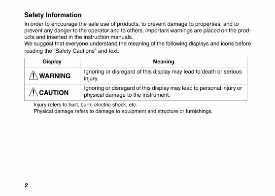
Safety InformationIn order to encourage the safe use of products, to prevent damage to properties, and toprevent any danger to the operator and to others, important warnings are placed on the prod-ucts and inserted in the instruction manuals.We suggest that everyone understand the meaning of the following displays and icons beforereading the “Safety Cautions” and text.
Injury refers to hurt, burn, electric shock, etc.Physical damage refers to damage to equipment and structure or furnishings.
Display Meaning
WARNINGIgnoring or disregard of this display may lead to death or serious injury.
CAUTIONIgnoring or disregard of this display may lead to personal injury or physical damage to the instrument.
3
Safety Cautions
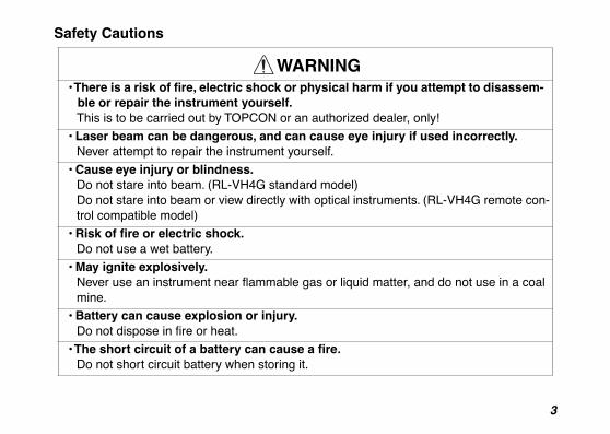
WARNING• There is a risk of fire, electric shock or physical harm if you attempt to disassem-
ble or repair the instrument yourself.This is to be carried out by TOPCON or an authorized dealer, only!
• Laser beam can be dangerous, and can cause eye injury if used incorrectly. Never attempt to repair the instrument yourself.
• Cause eye injury or blindness.Do not stare into beam. (RL-VH4G standard model)Do not stare into beam or view directly with optical instruments. (RL-VH4G remote con-trol compatible model)
• Risk of fire or electric shock.Do not use a wet battery.
• May ignite explosively.Never use an instrument near flammable gas or liquid matter, and do not use in a coal mine.
• Battery can cause explosion or injury.Do not dispose in fire or heat.
• The short circuit of a battery can cause a fire.Do not short circuit battery when storing it.
4
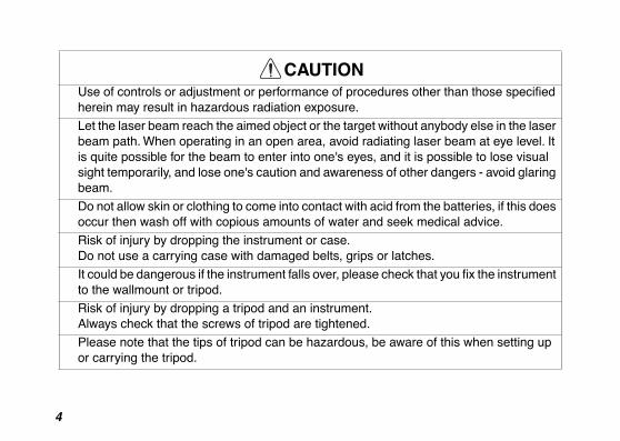
CAUTIONUse of controls or adjustment or performance of procedures other than those specified herein may result in hazardous radiation exposure.
Let the laser beam reach the aimed object or the target without anybody else in the laser beam path. When operating in an open area, avoid radiating laser beam at eye level. It is quite possible for the beam to enter into one's eyes, and it is possible to lose visual sight temporarily, and lose one's caution and awareness of other dangers - avoid glaring beam.
Do not allow skin or clothing to come into contact with acid from the batteries, if this does occur then wash off with copious amounts of water and seek medical advice.
Risk of injury by dropping the instrument or case.Do not use a carrying case with damaged belts, grips or latches.
It could be dangerous if the instrument falls over, please check that you fix the instrument to the wallmount or tripod.
Risk of injury by dropping a tripod and an instrument.Always check that the screws of tripod are tightened.
Please note that the tips of tripod can be hazardous, be aware of this when setting up or carrying the tripod.
5
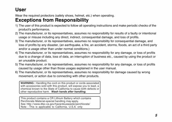
UserWear the required protectors (safety shoes, helmet, etc.) when operating.
Exceptions from Responsibility1) The user of this product is expected to follow all operating instructions and make periodic checks of the
product’s performance.2) The manufacturer, or its representatives, assumes no responsibility for results of a faulty or intentional
usage or misuse including any direct, indirect, consequential damage, and loss of profits.3) The manufacturer, or its representatives, assumes no responsibility for consequential damage, and
loss of profits by any disaster, (an earthquake, a fire, an accident, storms, floods, an act of a third partyand/or a usage other than under normal conditions.)
4) The manufacturer, or its representatives, assumes no responsibility for any damage, or loss of profits due to a change of data, loss of data, an interruption of business etc., caused by using the product or an unusable product.
5) The manufacturer, or its representatives, assumes no responsibility for any damage, or loss of profits caused by usage other than those usages explained in the user manual.
6) The manufacturer, or its representatives, assumes no responsibility for damage caused by wrong movement, or action due to connecting with other products.
6
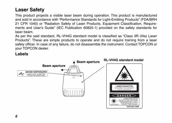
Laser SafetyThis product projects a visible laser beam during operation. This product is manufacturedand sold in accordance with “Performance Standards for Light-Emitting Products” (FDA/BRH21 CFR 1040) or “Radiation Safety of Laser Products, Equipment Classification, Require-ments and User’s Guide” (IEC Publication 60825-1) provided on the safety standards forlaser beam.As per the said standard, RL-VH4G standard model is classified as “Class 3R (IIIa) LaserProducts”. These are simple products to operate and do not require training from a lasersafety officer. In case of any failure, do not disassemble the instrument. Contact TOPCON oryour TOPCON dealer.
Labels
AVOID EXPOSURELASER LIGHT IS EMITTED
FROM THIS APERTURE
Beam apertureBeam aperture RL-VH4G standard model
7
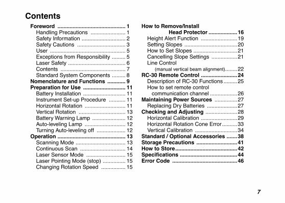
ContentsForeword ............................................. 1
Handling Precautions ....................... 1Safety Information ............................. 2Safety Cautions ................................ 3User .................................................. 5Exceptions from Responsibility ......... 5Laser Safety ...................................... 6Contents ........................................... 7Standard System Components ......... 8
Nomenclature and Functions ............ 9Preparation for Use ............................ 11
Battery Installation ............................ 11Instrument Set-up Procedure ........... 11Horizontal Rotation ........................... 11Vertical Rotation ............................... 13Battery Warning Lamp ...................... 12Auto-leveling Lamp ........................... 12Turning Auto-leveling off ................... 12
Operation ............................................. 13Scanning Mode ................................. 13Continuous Scan .............................. 14Laser Sensor Mode .......................... 15Laser Pointing Mode (stop) ............... 15Changing Rotation Speed ................ 15
How to Remove/Install Head Protector ...................16
Height Alert Function ........................19Setting Slopes ...................................20How to Set Slopes .............................21Cancelling Slope Settings .................21Line Control (manual vertical beam alignment)........22
RC-30 Remote Control ........................24Description of RC-30 Functions .........25How to set remote control communication channel ..................26
Maintaining Power Sources ...............27Replacing Dry Batteries ....................27
Checking and Adjusting .....................28Horizontal Calibration ........................29Horizontal Rotation Cone Error ..........33Vertical Calibration ............................34
Standard / Optional Accessories .......38Storage Precautions ...........................41How to Store.........................................42Specifications ......................................44Error Code ...........................................46
8
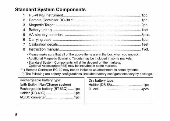
Standard System Components1 RL-VH4G Instrument.............................................................................1pc.2 Remote Controller RC-30 *1) ................................................................1pc.3 Magnetic Target ....................................................................................2pc.4 Battery unit *2) .......................................................................................1set5 AA-size dry batteries ...........................................................................3pcs.6 Carrying case .......................................................................................1pc.7 Calibration decals..................................................................................1set8 Instruction manual.................................................................................1vol.
• Please make sure that all of the above items are in the box when you unpack.• Additional Magnetic Scanning Targets may be included in some markets.• Standard System Components will differ depend on the markets.
Optional Accessories(P38) may be included in some markets.*1) Remote Controller RC-30 may not be included as attachment in some systems.
*2) The following are battery configurations. Included battery configurations vary by package.
Rechargeable battery type:(with Built-in Run/Charge system)Rechargeable battery (BT-63Q) ......1pc.Holder (DB-49C) .............................1pc.AC/DC converter .............................1pc.
Dry battery type:Holder (DB-58)................................1pc.D- cell............................................ 4pcs.
9
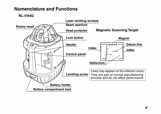
Nomenclature and Functions
Handle
Rotary head
Battery compartment lockBattery holder
Laser emitting windowBeam aperture
Leveling screw
Control panel
RL-VH4G
Magnetic Scanning Target
Magnet
Datum lineIndex
Index
Reflectors
Lines may appear on the reflector strips. They are part of normal manufacturing process and do not effect performance.
Head protector
Lock button
10
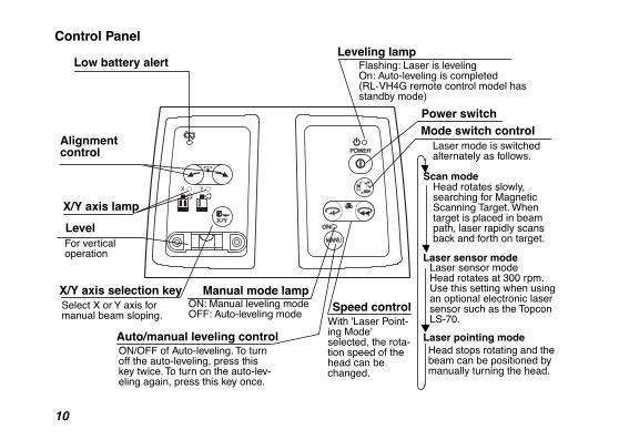
Control Panel
Auto/manual leveling control
Leveling lamp
Power switch
Manual mode lamp
Mode switch control
Scan mode
Laser sensor mode
Laser pointing mode
X/Y axis selection key
X/Y axis lamp
Head rotates slowly, searching for Magnetic Scanning Target. When target is placed in beam path, laser rapidly scans back and forth on target.
Laser sensor modeHead rotates at 300 rpm. Use this setting when using an optional electronic laser sensor such as the Topcon LS-70.
Head stops rotating and the beam can be positioned by manually turning the head.
Select X or Y axis for manual beam sloping.
ON: Manual leveling modeOFF: Auto-leveling mode
ON/OFF of Auto-leveling. To turn off the auto-leveling, press this key twice. To turn on the auto-lev-eling again, press this key once.
Flashing: Laser is levelingOn: Auto-leveling is completed (RL-VH4G remote control model has standby mode)
Laser mode is switched alternately as follows.
Speed controlWith 'Laser Point-ing Mode' selected, the rota-tion speed of the head can be changed.
Alignment control
Low battery alert
LevelFor vertical operation
11
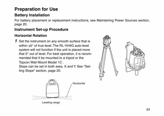
Preparation for UseBattery InstallationFor battery placement or replacement instructions, see Maintaining Power Sources section,page 20.
Instrument Set-up Procedure
Horizontal Rotation
1 Set the instrument on any smooth surface that is within ±5° of true level. The RL-VH4G auto-level system will not function if the unit is placed more that 5° out of level. For best operation, it is recom-mended that it be mounted to a tripod or the Topcon Wall Mount Model 1C .Slope can be set in both axes, X and Y. See "Set-ting Slope" section, page 20.
Horizontal
Leveling range
12
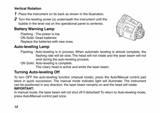
Vertical Rotation
1 Place the instrument on its back as shown in the illustration.
2 Turn the leveling screw (s) underneath the instrument until the bubble in the level vial on the operational panel is centered.
Battery Warning LampFlashing : The power is lowON Solid: Dead batteriesReplace the batteries with new ones.
Auto-leveling LampFlashing : Auto-leveling is in process. When automatic leveling is almost complete, the
flashing rate will be slow. The head will not rotate and the laser beam will notemit during the auto-leveling process.
ON Solid: Auto-leveling is complete.The rotary head is active and emits the laser beam.
Turning Auto-leveling OffTo turn OFF the auto-leveling function (manual mode), press the Auto/Manual control padtwice in quick succession. The manual mode indicator light will illuminate. The instrumentcan be positioned in any direction, the laser beam remains on and the head will rotate.IMPORTANT: In manual mode, the laser beam will not shut off if disturbed! To return to Auto-leveling mode,press Auto/Manual control pad once.
13
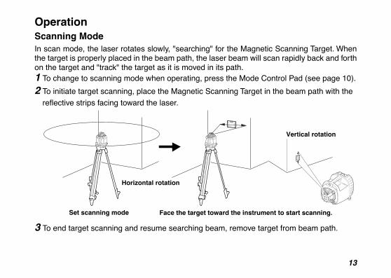
OperationScanning ModeIn scan mode, the laser rotates slowly, "searching" for the Magnetic Scanning Target. Whenthe target is properly placed in the beam path, the laser beam will scan rapidly back and forthon the target and "track" the target as it is moved in its path.1 To change to scanning mode when operating, press the Mode Control Pad (see page 10).
2 To initiate target scanning, place the Magnetic Scanning Target in the beam path with the
reflective strips facing toward the laser.
3 To end target scanning and resume searching beam, remove target from beam path.
Vertical rotation
Horizontal rotation
Set scanning mode Face the target toward the instrument to start scanning.
14
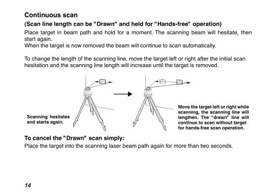
Continuous scan (Scan line length can be "Drawn" and held for "Hands-free" operation)Place target in beam path and hold for a moment. The scanning beam will hesitate, thenstart again. When the target is now removed the beam will continue to scan automatically.
To change the length of the scanning line, move the target left or right after the initial scanhesitation and the scanning line length will increase until the target is removed.
To cancel the "Drawn" scan simply:Place the target into the scanning laser beam path again for more than two seconds.
Scanning hesitatesand starts again.
Move the target left or right whilescanning, the scanning line willlengthen. The "drawn" line willcontinue to scan without targetfor hands-free scan operation.
15
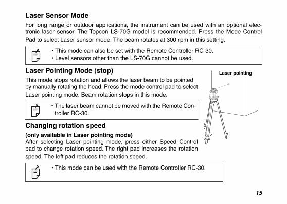
Laser Sensor ModeFor long range or outdoor applications, the instrument can be used with an optional elec-tronic laser sensor. The Topcon LS-70G model is recommended. Press the Mode ControlPad to select Laser sensor mode. The beam rotates at 300 rpm in this setting.
Laser Pointing Mode (stop)This mode stops rotation and allows the laser beam to be pointedby manually rotating the head. Press the mode control pad to selectLaser pointing mode. Beam rotation stops in this mode.
Changing rotation speed (only available in Laser pointing mode)After selecting Laser pointing mode, press either Speed Controlpad to change rotation speed. The right pad increases the rotationspeed. The left pad reduces the rotation speed.
• This mode can also be set with the Remote Controller RC-30.• Level sensors other than the LS-70G cannot be used.
• The laser beam cannot be moved with the Remote Con-troller RC-30.
• This mode can be used with the Remote Controller RC-30.
Laser pointing
16
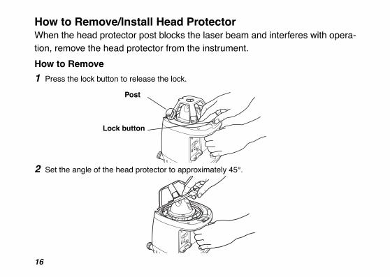
How to Remove/Install Head ProtectorWhen the head protector post blocks the laser beam and interferes with opera-tion, remove the head protector from the instrument.
How to Remove
1 Press the lock button to release the lock.
2 Set the angle of the head protector to approximately 45°.
Post
Lock button
17
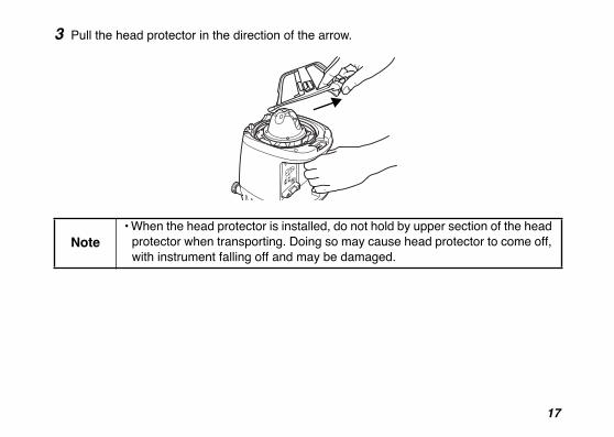
3 Pull the head protector in the direction of the arrow.
Note• When the head protector is installed, do not hold by upper section of the head
protector when transporting. Doing so may cause head protector to come off, with instrument falling off and may be damaged.

18
How to Install1 Insert the head protector pin into the groove of the instrument until you feel it click.
2 Bring down the head protector until you hear a clicking sound.
3 Check that the head protector is securely locked.
Pin, Groove

19
Height Alert functionWhen auto-leveling and height alert function are active, this function prevents the instru-ment from operating if it is disturbed (after the laser beam emits for one minute). Thishelps insures accurate control. If the height or inclination of the instrument changes, theheight of instrument should be verified and re-established if necessary.
1 To activate the Height Alert function, depress and
hold the left Alignment control pad (see page 10) on the control panel while turning on the instrument by pressing the Power control pad. The three LEDs (Leveling, Manual, Battery) will flash at the same time
for three seconds.
2 When this function is active and the unit is disturbed,
three visible LEDs will rapidly flash.
3 To re-activate auto-leveling and check the beam height, turn the unit off, then on again by
pressing the Power control pad twice. After auto-leveling is complete, check the beam height to confirm it has not changed.
4 The Height Alert function is now inactive. To re-activate, turn unit off and repeat step 1.
Battery LED
Leveling LED
Manual LED
20
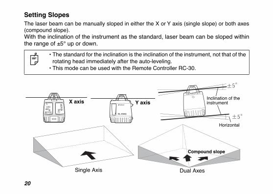
Setting SlopesThe laser beam can be manually sloped in either the X or Y axis (single slope) or both axes(compound slope).With the inclination of the instrument as the standard, laser beam can be sloped withinthe range of ±5° up or down.
• The standard for the inclination is the inclination of the instrument, not that of the rotating head immediately after the auto-leveling.
• This mode can be used with the Remote Controller RC-30.
X axis Y axis
Single Axis Dual Axes
Compound slope
Horizontal
Inclination of the instrument
21
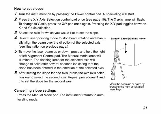
How to set slopes
1 Turn the instrument on by pressing the Power control pad. Auto-leveling will start.
2 Press the X/Y Axis Selection control pad once (see page 10). The X axis lamp will flash. To change to Y axis, press the X/Y pad once again. Pressing the X/Y pad toggles between X and Y axis selection.
3 Select the axis for which you would like to set the slope.
4 Select Laser pointing mode to stop beam rotation and manu-ally align the beam over the direction of the selected axis (see illustration on previous page.)
5 To move the laser beam up or down, press and hold the right or left Alignment Control pad. The Manual mode lamp will illuminate. The flashing lamp for the selected axis will change to solid after several seconds indicating that the slope has been entered in the direction of the selected axis.
6 After setting the slope for one axis, press the X/Y axis selec-tion key to select the second axis. Repeat procedures 4 and 5 to set the slope for the second axis.
Cancelling slope settings Press the Manual Mode pad. The instrument returns to auto-leveling mode.
Sample; Laser pointing mode
Move the beam up or down by pressing the right or left align-ment keys
22
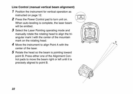
Line Control (manual vertical beam alignment)
1 Position the instrument for vertical operation as instructed on page 12.
2 Press the Power Control pad to turn unit on. When auto-leveling is complete, the laser beam will be emitted.
3 Select the Laser Pointing operating mode and manually rotate the rotating head to align the tri-angular mark t with the center of the mountain mark on the rotating head.
4 Move the instrument to align Point A with the center of the laser.
5 Rotate the head so the beam is pointing toward point B. Press either one of the Alignment Con-trol pads to move the beam right or left until it is precisely aligned to point B.
23
6 Select the operating mode using the Mode Control pad best suited for your application.
• This mode can be used with the Remote Controller RC-30.• While an alignment control pad is pressed the auto-leveling beam shut-off will not
operate.
24
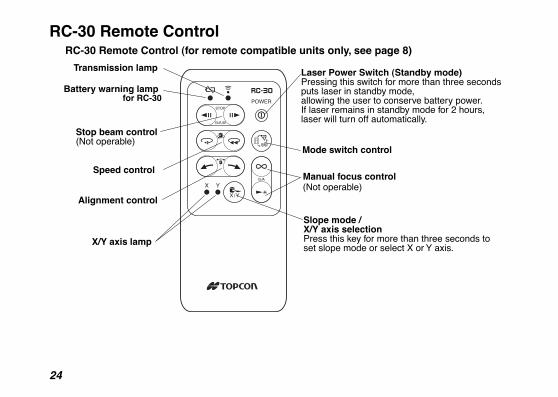
RC-30 Remote Control
Battery warning lamp for RC-30
Transmission lamp Laser Power Switch (Standby mode)Pressing this switch for more than three seconds puts laser in standby mode,allowing the user to conserve battery power.If laser remains in standby mode for 2 hours, laser will turn off automatically.
Mode switch control
Slope mode / X/Y axis selectionPress this key for more than three seconds to set slope mode or select X or Y axis.
X/Y axis lamp
Alignment control
Speed control
Stop beam control(Not operable)
Manual focus control(Not operable)
RC-30 Remote Control (for remote compatible units only, see page 8)
25
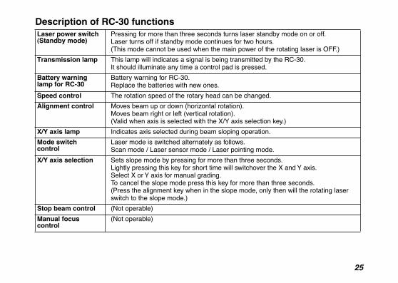
Description of RC-30 functionsLaser power switch(Standby mode)
Pressing for more than three seconds turns laser standby mode on or off. Laser turns off if standby mode continues for two hours.(This mode cannot be used when the main power of the rotating laser is OFF.)
Transmission lamp This lamp will indicates a signal is being transmitted by the RC-30.It should illuminate any time a control pad is pressed.
Battery warning lamp for RC-30
Battery warning for RC-30. Replace the batteries with new ones.
Speed control The rotation speed of the rotary head can be changed.
Alignment control Moves beam up or down (horizontal rotation).Moves beam right or left (vertical rotation).(Valid when axis is selected with the X/Y axis selection key.)
X/Y axis lamp Indicates axis selected during beam sloping operation.
Mode switch control
Laser mode is switched alternately as follows.Scan mode / Laser sensor mode / Laser pointing mode.
X/Y axis selection Sets slope mode by pressing for more than three seconds. Lightly pressing this key for short time will switchover the X and Y axis.Select X or Y axis for manual grading.To cancel the slope mode press this key for more than three seconds.(Press the alignment key when in the slope mode, only then will the rotating laser switch to the slope mode.)
Stop beam control (Not operable)
Manual focus control
(Not operable)
26
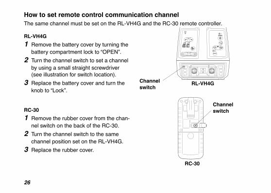
How to set remote control communication channelThe same channel must be set on the RL-VH4G and the RC-30 remote controller.
RL-VH4G
1 Remove the battery cover by turning the battery compartment lock to “OPEN”.
2 Turn the channel switch to set a channel by using a small straight screwdriver (see illustration for switch location).
3 Replace the battery cover and turn the knob to “Lock”.
RC-30
1 Remove the rubber cover from the chan-nel switch on the back of the RC-30.
2 Turn the channel switch to the same channel position set on the RL-VH4G.
3 Replace the rubber cover.
098765 4 3 2 1
X Y
9
8 7 6 5 4
3 2
1 0
RC-30
RL-VH4G
Channelswitch
Channelswitch
27
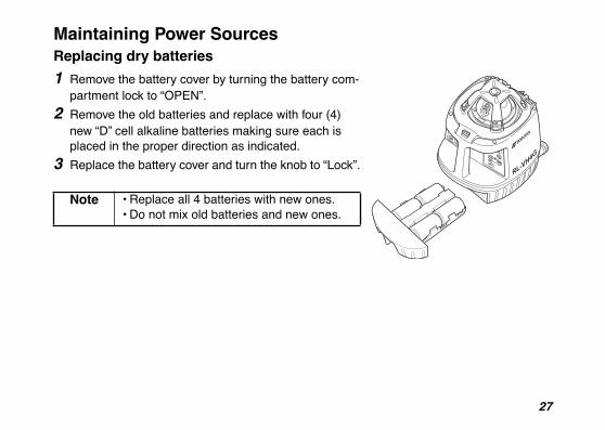
Maintaining Power SourcesReplacing dry batteries
1 Remove the battery cover by turning the battery com-partment lock to “OPEN”.
2 Remove the old batteries and replace with four (4) new “D” cell alkaline batteries making sure each is placed in the proper direction as indicated.
3 Replace the battery cover and turn the knob to “Lock”.
Note • Replace all 4 batteries with new ones.• Do not mix old batteries and new ones.
28
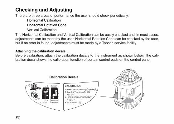
Checking and AdjustingThere are three areas of performance the user should check periodically.
Horizontal CalibrationHorizontal Rotation ConeVertical Calibration
The Horizontal Calibration and Vertical Calibration can be easily checked and, in most cases,adjustments can be made by the user. Horizontal Rotation Cone can be checked by the user,but if an error is found, adjustments must be made by a Topcon service facility.
Attaching the calibration decalsBefore calibration, attach the calibration decals to the instrument as shown below. The cali-bration decal shows the calibration function of certain control pads on the control panel.
CALIBRATIONSTART-While pressing ,pressXCAL-ON,YCAL-press ONVCAL-ONLASER BEAM CORRECTION- orENTER-press
START
1
1
X VY
2
3
ENTERERROR
4
2
3
4
X/Y
X/Y
X
Y
V
Calibration Decals
29
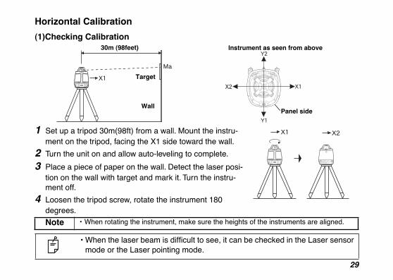
Horizontal Calibration
(1)Checking Calibration
1 Set up a tripod 30m(98ft) from a wall. Mount the instru-ment on the tripod, facing the X1 side toward the wall.
2 Turn the unit on and allow auto-leveling to complete.
3 Place a piece of paper on the wall. Detect the laser posi-tion on the wall with target and mark it. Turn the instru-ment off.
4 Loosen the tripod screw, rotate the instrument 180 degrees.
Note • When rotating the instrument, make sure the heights of the instruments are aligned.
• When the laser beam is difficult to see, it can be checked in the Laser sensor mode or the Laser pointing mode.
30m (98feet)
Target
Wall
Instrument as seen from above
Panel side
30
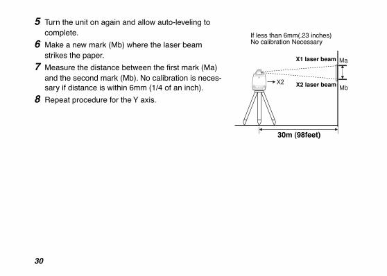
5 Turn the unit on again and allow auto-leveling to complete.
6 Make a new mark (Mb) where the laser beam strikes the paper.
7 Measure the distance between the first mark (Ma) and the second mark (Mb). No calibration is neces-sary if distance is within 6mm (1/4 of an inch).
8 Repeat procedure for the Y axis.
30m (98feet)
X1 laser beam
X2 laser beam
If less than 6mm(.23 inches) No calibration Necessary

31
(2) Adjusting CalibrationIf the distance between either set of marks is more than 6mm (1/4 of an inch) but less than25mm (1 inch), turn the unit off by pressing the [START] pad once and use the followingprocedure to calibrate the laser. Confirm that unit has shut off before beginning the proce-dure.(In steps 2 and 3, use of optional RC-30 remote control can be helpful. See page 33.)
1 While pressing the [ENTER] key, press the [START] key. This activates the X axis calibra-tion mode. Confirm that the [X] LED is lit.
2 By pressing the right or left Alignment Control pad, move the X2 (Mb) laser beam up or
down until its centered between marks Ma and Mb.
Note• This operation can be performed with the Remote Controller RC-30.• When using the RC-30, select the X axis with the X/Y axis selection key and
move the laser beam up or down with the alignment key.
START1
X VY
2
3
ENTERERROR
4
X/YLaser beam up or down
Center position
32
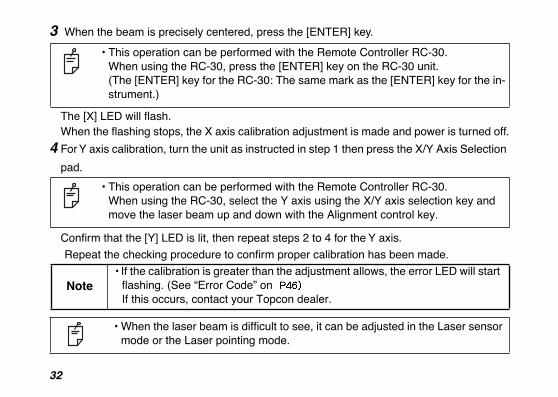
3 When the beam is precisely centered, press the [ENTER] key.
The [X] LED will flash.When the flashing stops, the X axis calibration adjustment is made and power is turned off.
4 For Y axis calibration, turn the unit as instructed in step 1 then press the X/Y Axis Selection
pad.
Confirm that the [Y] LED is lit, then repeat steps 2 to 4 for the Y axis.
Repeat the checking procedure to confirm proper calibration has been made.
• This operation can be performed with the Remote Controller RC-30.When using the RC-30, press the [ENTER] key on the RC-30 unit. (The [ENTER] key for the RC-30: The same mark as the [ENTER] key for the in-strument.)
• This operation can be performed with the Remote Controller RC-30.When using the RC-30, select the Y axis using the X/Y axis selection key and move the laser beam up and down with the Alignment control key.
Note• If the calibration is greater than the adjustment allows, the error LED will start
flashing. (See “Error Code” on If this occurs, contact your Topcon dealer.
• When the laser beam is difficult to see, it can be adjusted in the Laser sensor mode or the Laser pointing mode.
33
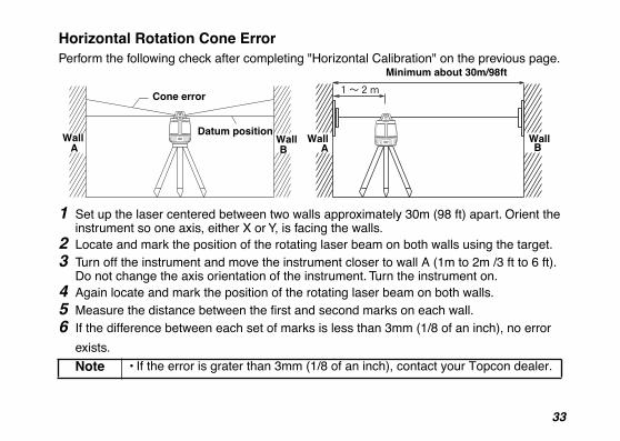
Horizontal Rotation Cone Error
Perform the following check after completing "Horizontal Calibration" on the previous page.
1
Set up the laser centered between two walls approximately 30m (98 ft) apart. Orient the instrument so one axis, either X or Y, is facing the walls.
2
Locate and mark the position of the rotating laser beam on both walls using the target.
3
Turn off the instrument and move the instrument closer to wall A (1m to 2m /3 ft to 6 ft).Do not change the axis orientation of the instrument. Turn the instrument on.
4
Again locate and mark the position of the rotating laser beam on both walls.
5 Measure the distance between the first and second marks on each wall. 6
If the difference between each set of marks is less than 3mm (1/8 of an inch), no error
exists.
Note
• If the error is grater than 3mm (1/8 of an inch), contact your Topcon dealer.
Cone error
Datum positionWall Wall BA
Wall A
Wall B
Minimum about 30m/98ft
34
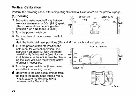
Vertical Calibration
Perform the following check after completing "Horizontal Calibration" on the previous page.
(1)Checking
1
Set up the instrument half way between two walls a minimum of 30m (98 ft) apart. (The instrument can be facing either direction X or Y. No tripod is used.)
2
Turn the power switch on.
3
Place a piece of paper on each wall (A and B).Mark the horizontal laser positions (Ma and Mb) on each wall using target.
4
Turn the power switch off. Position the instrument for vertical operation (see instruction on page 12) with the rotary head directly facing wall A (see illustra-tion). Make sure the unit is level by check-ing the level vial. Use the leveling screw to adjust if necessary.
5
Turn the power switch on. (Laser beam should be in scanning mode.)
6
Mark where the split beam emitted from the top of the rotary head strikes wall A (Ha). Measure the distance (dHa) between marks Ma and Ha.
about 15 m (49ft)
about 15 m (49ft)
Wall A
Wall B
about 30 m (98ft)
Wall A Wall
B
about 1m
Foot
35
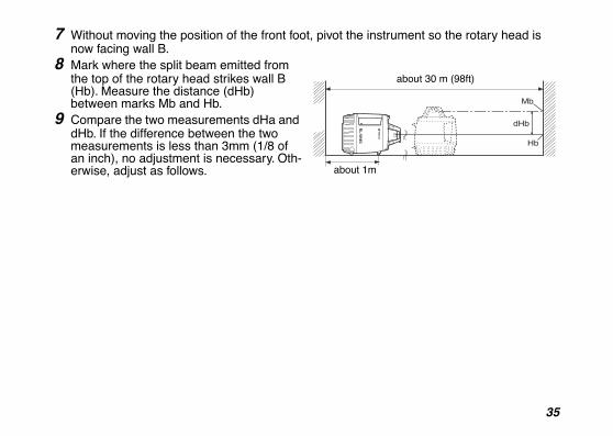
7
Without moving the position of the front foot, pivot the instrument so the rotary head is now facing wall B.
8
Mark where the split beam emitted from the top of the rotary head strikes wall B (Hb). Measure the distance (dHb) between marks Mb and Hb.
9
Compare the two measurements dHa and dHb. If the difference between the two measurements is less than 3mm (1/8 of an inch), no adjustment is necessary. Oth-erwise, adjust as follows. about 1m
about 30 m (98ft)
36
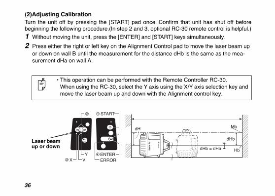
(2)Adjusting Calibration
Turn the unit off by pressing the [START] pad once. Confirm that unit has shut off beforebeginning the following procedure.(In step 2 and 3, optional RC-30 remote control is helpful.)
1
Without moving the unit, press the [ENTER] and [START] keys simultaneously.
2
Press either the right or left key on the Alignment Control pad to move the laser beam up or down on wall B until the measurement for the distance dHb is the same as the mea-surement dHa on wall A.
• This operation can be performed with the Remote Controller RC-30.When using the RC-30, select the Y axis using the X/Y axis selection key and move the laser beam up and down with the Alignment control key.
START1
X VY
2
3
ENTERERROR
4
X/Y Laser beam up or down
37
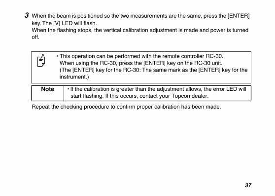
3
When the beam is positioned so the two measurements are the same, press the [ENTER] key. The [V] LED will flash.When the flashing stops, the vertical calibration adjustment is made and power is turned off.
Repeat the checking procedure to confirm proper calibration has been made.
• This operation can be performed with the remote controller RC-30.When using the RC-30, press the [ENTER] key on the RC-30 unit.(The [ENTER] key for the RC-30: The same mark as the [ENTER] key for the instrument.)
Note • If the calibration is greater than the adjustment allows, the error LED will start flashing. If this occurs, contact your Topcon dealer.
38
Standard / Optional Accessories
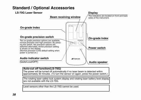
Auto-cut off function(LS-70G)The power will be turned off automatically if no laser beam is detected within approximately 30 minutes. (To turn the sensor on again, press the power switch.)
Two on-grade precision options are available, normal precision and high precision. By press-ing this switch, the precision options are switched alternately. Active precision settingis shown on the display.(Normal precision is the default setting whenpower is turned on.)
On-grade precision switch
Audio indicator switch(Quite/Loud/OFF) Audio speaker
Beam receiving window
Power switch
LS-70G Laser Sensor
On-grade Index
Display
On-grade Index
The indicators are located on front and back sides of the instrument.
The rotating laser safety lock system display and rotating laser battery level display are not available with the LS-70G.
Level sensors other than the LS-70G cannot be used.
39
154
152
150
153
151
138
136
134
132
139
137
135
133
131
131
149
147
148
146
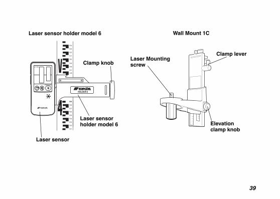
HOLDER-6
Laser sensor holder model 6
Laser sensor holder model 6
Clamp knob
Laser sensor
Wall Mount 1C
Clamp leverLaser Mounting screw
Elevation clamp knob
40
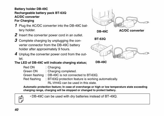
Battery holder DB-49C Rechargeable battery pack BT-63Q AC/DC converter For Charging
1 Plug the AC/DC converter into the DB-49C bat-tery holder.
2 Insert the converter power cord in an outlet.
3 Complete charging by unplugging the con-verter connector from the DB-49C battery holder after approximately 9 hours.
4 Unplug the converter power cord from the out-let.
The LED of DB-49C will indicate charging status;
Red ON : Charging.Green ON : Charging completed.Green flashing : DB-49C is not connected to BT-63Q.Red flashing : BT-63Q protection feature is working automatically.
RL-VH4G can be used in this state.Automatic protection feature; In case of overcharge or high or low temperature state exceeding charging range, charging will be stopped or changed to protect battery.
• DB-49C can be used with dry batteries instead of BT-49Q.
DB-49C AC/DC converter
BT-63Q
DB-49C
41
Storage PrecautionsAlways clean the instrument after use.Use a clean cloth, moistened with a neutral detergent or water. Never use an abrasivecleaner, ether, thinner benzene, or other solvents.
Always make sure instrument is completely dry before storing. Dry any moisture with a soft,clean cloth.
42
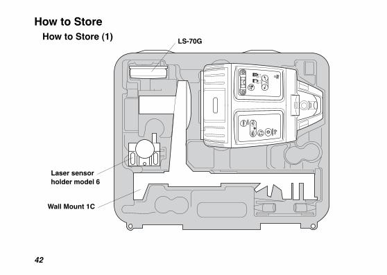
How to StoreHow to Store (1) LS-70G
Laser sensor holder model 6
Wall Mount 1C
43
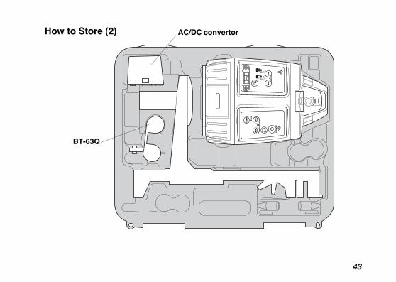
AC/DC convertorHow to Store (2)
BT-63Q
44
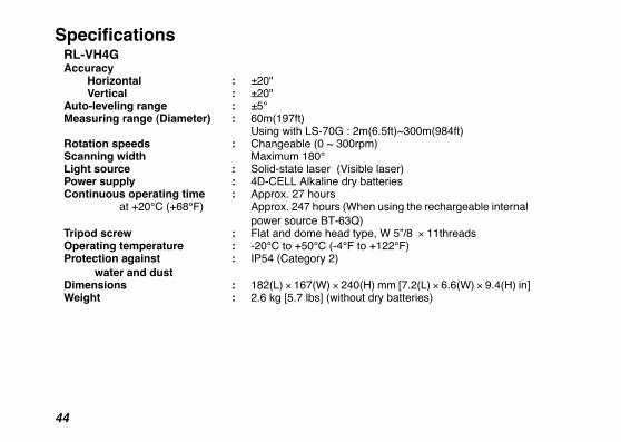
SpecificationsRL-VH4GAccuracy
Horizontal : ±20"Vertical : ±20"
Auto-leveling range : ±5°Measuring range (Diameter) : 60m(197ft) Using with LS-70G : 2m(6.5ft)~300m(984ft)Rotation speeds : Changeable (0 ~ 300rpm)Scanning width Maximum 180°Light source : Solid-state laser (Visible laser)Power supply : 4D-CELL Alkaline dry batteries Continuous operating time : Approx. 27 hours at +20°C (+68°F) Approx. 247 hours (When using the rechargeable internal
power source BT-63Q)Tripod screw : Flat and dome head type, W 5”/8 × 11threadsOperating temperature : -20°C to +50°C (-4°F to +122°F)Protection against water and dust
: IP54 (Category 2)
Dimensions : 182(L) × 167(W) × 240(H) mm [7.2(L) × 6.6(W) × 9.4(H) in]Weight : 2.6 kg [5.7 lbs] (without dry batteries)
45
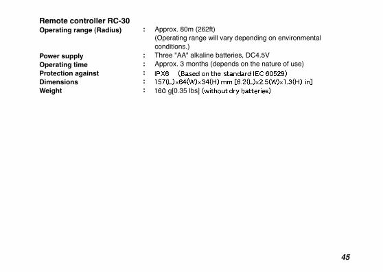
Remote controller RC-30 Operating range (Radius)
Power supplyOperating timeProtection againstDimensionsWeight
:
:::::
Approx. 80m (262ft)(Operating range will vary depending on environmental conditions.) Three "AA" alkaline batteries, DC4.5VApprox. 3 months (depends on the nature of use)
× × × × g[0.35 lbs]
46
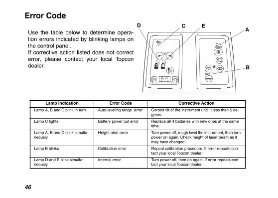
Error Code
Use the table below to determine opera-tion errors indicated by blinking lamps onthe control panel. If corrective action listed does not correcterror, please contact your local Topcondealer.
Lamp Indication Error Code Corrective Action
Lamp A, B and C blink in turn Auto-leveling range error Correct tilt of the instrument until it less than 5 de-grees.
Lamp C lights Battery power out error Replace all 4 batteries with new ones at the same time.
Lamp A, B and C blink simulta-neously
Height alert error Turn power off, rough level the instrument, then turn power on again. Check height of laser beam as it may have changed.
Lamp B blinks Calibration error Repeat calibration procedure. If error repeats con-tact your local Topcon dealer.
Lamp D and E blink simulta-neously
Internal error Turn power off, then on again. If error repeats con-tact your local Topcon dealer.
C EDA
B

2006 TOPCON CORPORATIONALL RIGHTS RESERVED

TOPCON CORPORATION75-1 Hasunuma-cho, Itabashi-ku, Tokyo 174-8580, Japan Phone: 3-3558-2520 Fax: 3-3960-4214 www.topcon.co.jp
TOPCON POSITIONING SYSTEMS, INC.7400 National Drive, Livermore, CA 94551, U.S.A.Phone: 925-245-8300 Fax: 925-245-8599 www.topcon.comTOPCON CALIFORNIA3380 Industrial Blvd, Suite 105, West Sacramento, CA 95691, U.S.A.Phone: 916-374-8575 Fax: 916-374-8329
TOPCON EUROPE POSITIONING B.V.Essebaan 11, 2908 LJ Capelle a/d IJssel, The Netherlands.Phone: 010-458-5077 Fax: 010-284-4941 www.topconeurope.com
TOPCON DEUTSCHLAND G.m.b.H.Giesserallee 31, 47877 Willich, GERMANYPhone: 02154-885-100 Fax: 02154-885-111 [email protected]
TOPCON S.A.R.L. 89, Rue de Paris, 92585 Clichy, Cedex, France.Phone: 33-1-41069490 Fax: 33-1-47390251 [email protected]
TOPCON SCANDINAVIA A. B. Neongatan 2 S-43151 Mölndal, SWEDENPhone: 031-7109200 Fax: 031-7109249
TOPCON (GREAT BRITAIN)LTD.Topcon House Kennet Side, Bone Lane, Newbury, Berkshire RG14 5PX U.K.Phone: 44-1635-551120 Fax: [email protected] [email protected]
TOPCON SOUTH ASIA PTE. LTD.Blk 192 Pandan Loop, #07-01 Pantech Industrial Complex, Singapore 128381Phone: 62780222 Fax: 62733540 www.topcon.com.sg
TOPCON INSTRUMENTS (THAILAND) CO., LTD.77/162 Sinn Sathorn Tower, 37th Fl.,Krungdhonburi Rd., Klongtonsai, Klongsarn, Bangkok 10600 Thailand.Phone: 02-440-1152~7 Fax: 02-440-1158
TOPCON INSTRUMENTS (MALAYSIA) SDN. BHD.Excella Business Park Block C, Ground & 1st Floor, Jalan Ampang Putra, Taman Ampang Hilir, 55100 Kuala Lumpur, MALAYSIA Phone: 03-42701068 Fax: 03-42704508
TOPCON KOREA CORPORATION2F Yooseoung Bldg., 1595-3, Seocho-Dong, Seocho-gu, Seoul, 137-876, Korea.Phone: 82-2-2055-0321 Fax: 82-2-2055-0319 www.topcon.co.kr
TOPCON OPTICAL (H.K.) LIMITED2-4/F Meeco Industrial Bldg., No. 53-55 Au Pui Wan Street, Fo Tan Road, Shatin, N.T., Hong KongPhone: 2690-1328 Fax: 2690-2221 www.topcon.com.hk
TOPCON CORPORATION BEIJING OFFICEBuilding A No.9, Kangding StreetBeijing Economic Technological Development Area, Beijing, China 100176Phone: 10-6780-2799 Fax: 10-6780-2790
TOPCON CORPORATION BEIRUT OFFICEP. O. BOX 70-1002 Antelias, BEIRUT-LEBANON. Phone: 961-4-523525/961-4-523526 Fax: 961-4-521119
TOPCON CORPORATION DUBAI OFFICEC/O Atlas Medical FZCO., P. O. Box 54304, C-25, Dubai Airport Free Zone,UAEPhone: 971-4-2995900 Fax: 971-4-2995901
IRELAND OFFICEUnit 69 Western Parkway Business Center
Phone: 01460-0021 Fax: 01460-0129Lower Ballymount Road, Dublin 12, Lreland
3C