Embed Size (px)
Citation preview
eliteaccess.com
®
ACCESS SYSTEMS INCACCESS SYSTEMS INC
Instruction Manual
ROBO SLIDEResidential Gate Operator
Installation instructions and manual book for architects, general contractors and dealers
Copyright © 2000 by Elite Access Systems, Inc. – www.eliteaccess.com
Click on the desired topic in the “Bookmarks” column or “Table of Contents” to select page.
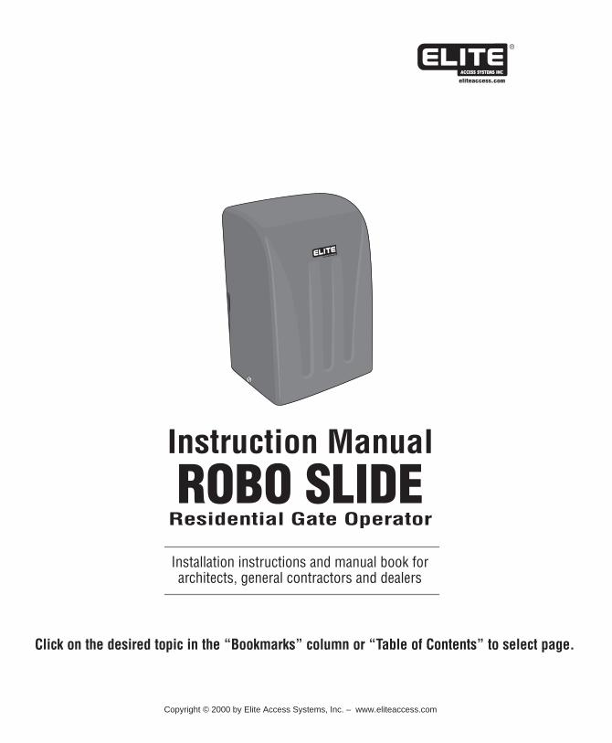
T A B L E O F C O N T E N T S
Important NoticeSafely Operating GateConfiguration and SpecificationsWarnings and Precautions Step 1: Getting Started Step 2: Mounting Operator Step 3: Chain Installation Step 4: Gate Movement Direction Step 5: DC Power Supply Connection Step 6: “Optional” Solar Panel Step 7: Terminal Connections Step 8: Adjusting Gate Travel Distance Step 9: Timer Step 10: 2-Way Adjustable Reversing Sensor“Optional” Input BoardMaster and Slave Operators with TimerMaster and Slave Operators without TimerControl Board FunctionsLED DescriptionsTroubleshooting How to Reset Breaker Switch How to Check Fuses Gate will not close! Gate will not open! If you hear a “BEEP” soundRobo Slide Parts ListRobo Slide Parts
2345566789
1011111213141516
17-18
19192020212122
PLEASE DO NOT TOUCH ME!...UNLESS YOU ARE AN AUTHORIZED SERVICE TECHNICIAN!
© COPYRIGHT 1992 BY ELITE ACCESS SYSTEMS, INC.
Release 6
All rights reserved. No part of this manual may be reproduced in any means; graphic, electronic, mechanical, or photocopied without the express written permission of the publisher of this material
1
5/01
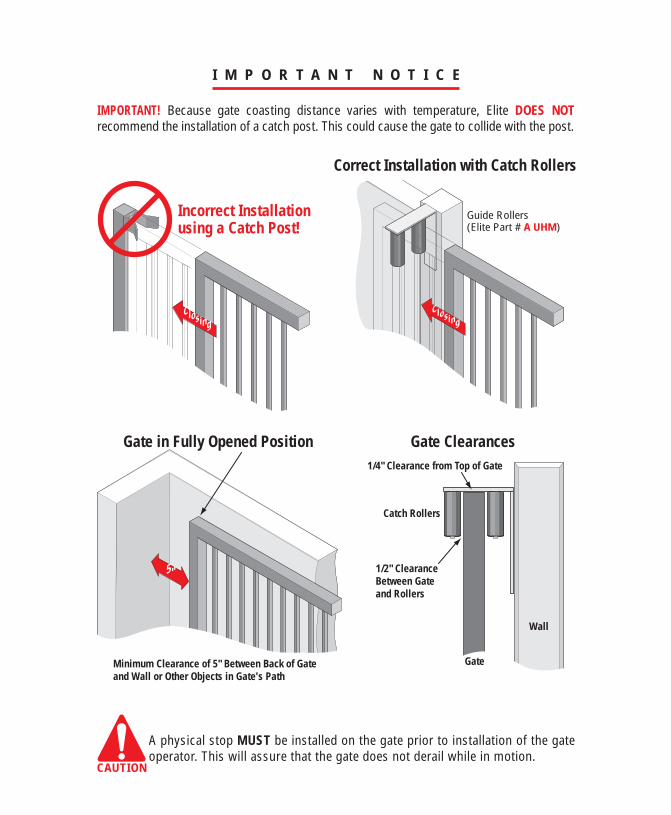
I M P O R T A N T N O T I C E
ClosingClosing
Incorrect Installationusing a Catch Post!
Correct Installation with Catch Rollers
Wall
Catch Rollers
Gate
1/2" ClearanceBetween Gateand Rollers
Minimum Clearance of 5" Between Back of Gate and Wall or Other Objects in Gate's Path
1/4" Clearance from Top of Gate
5"
A physical stop MUST be installed on the gate prior to installation of the gate operator. This will assure that the gate does not derail while in motion.
CAUTION
Gate in Fully Opened Position Gate Clearances
IMPORTANT! Because gate coasting distance varies with temperature, Elite DOES NOT recommend the installation of a catch post. This could cause the gate to collide with the post.
Guide Rollers(Elite Part # A UHM)
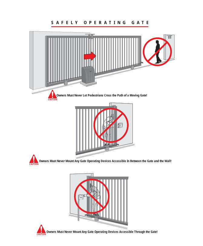
S A F E L Y O P E R A T I N G G A T E
Owners Must Never Let Pedestrians Cross the Path of a Moving Gate!
Owners Must Never Mount Any Gate Operating Devices Accessible In Between the Gate and the Wall!
Owners Must Never Mount Any Gate Operating Devices Accessible Through the Gate!
CAUTION
CAUTION
CAUTION
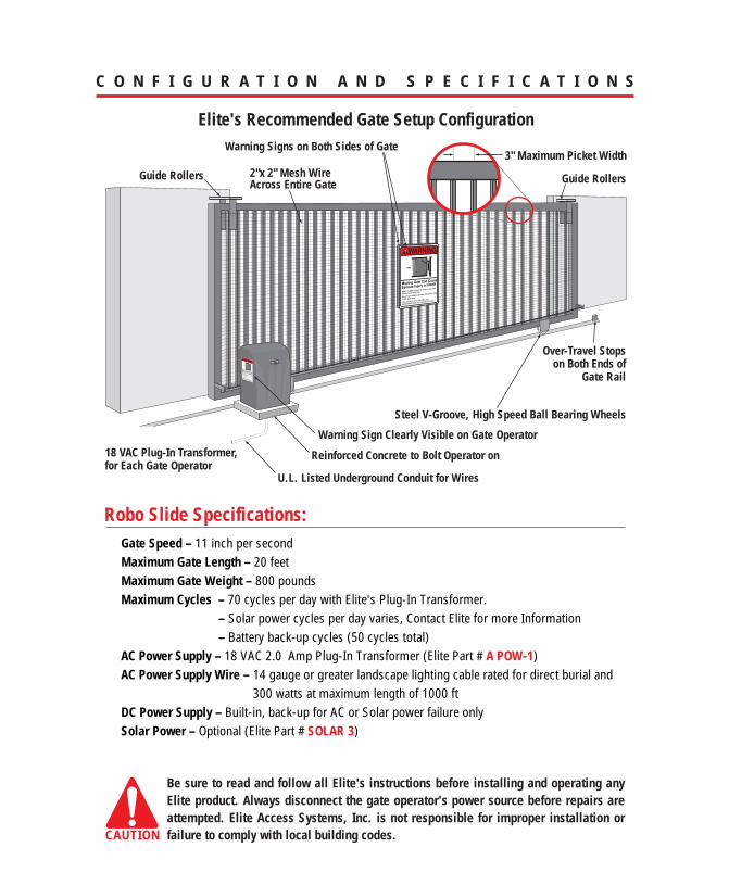
C O N F I G U R A T I O N A N D S P E C I F I C A T I O N S
Elite's Recommended Gate Setup ConfigurationWarning Signs on Both Sides of Gate
Over-Travel Stopson Both Ends of
Gate Rail
Guide Rollers Guide Rollers2"x 2" Mesh Wire Across Entire Gate
Warning Sign Clearly Visible on Gate Operator
Be sure to read and follow all Elite's instructions before installing and operating any Elite product. Always disconnect the gate operator's power source before repairs are attempted. Elite Access Systems, Inc. is not responsible for improper installation or failure to comply with local building codes.CAUTION
Robo Slide Specifications:Gate Speed – 11 inch per secondMaximum Gate Length – 20 feet Maximum Gate Weight – 800 poundsMaximum Cycles – 70 cycles per day with Elite's Plug-In Transformer.
– Solar power cycles per day varies, Contact Elite for more Information– Battery back-up cycles (50 cycles total)
AC Power Supply – 18 VAC 2.0 Amp Plug-In Transformer (Elite Part # A POW-1)AC Power Supply Wire – 14 gauge or greater landscape lighting cable rated for direct burial and
300 watts at maximum length of 1000 ft DC Power Supply – Built-in, back-up for AC or Solar power failure onlySolar Power – Optional (Elite Part # SOLAR 3)
Reinforced Concrete to Bolt Operator on18 VAC Plug-In Transformer, for Each Gate Operator
U.L. Listed Underground Conduit for Wires
3" Maximum Picket Width
Steel V-Groove, High Speed Ball Bearing Wheels
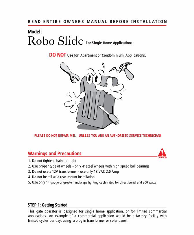
R E A D E N T I R E O W N E R S M A N U A L B E F O R E I N S TA L L AT I O N
CAUTION
Model:
Warnings and Precautions
DO NOT Use for Apartment or Condominium Applications.
1. Do not tighten chain too tight2. Use proper type of wheels - only 4" steel wheels with high speed ball bearings3. Do not use a 12V transformer - use only 18 VAC 2.0 Amp 4. Do not install as a rear-mount installation5. Use only 14 gauge or greater landscape lighting cable rated for direct burial and 300 watts
Robo Slide For Single Home Applications.
STEP 1: Getting Started This gate operator is designed for single home application, or for limited commercial applications. An example of a commercial application would be a factory facility with limited cycles per day, using a plug in transformer or solar panel.
PLEASE DO NOT REPAIR ME!...UNLESS YOU ARE AN AUTHORIZED SERVICE TECHNICIAN!
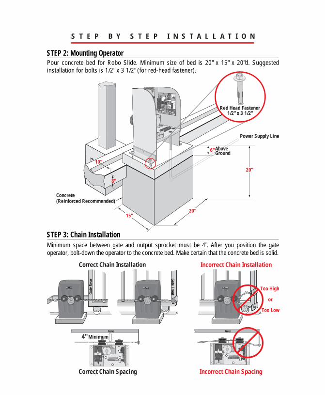
Correct Chain Installation Incorrect Chain Installation
Too High
Too Low
S T E P B Y S T E P I N S T A L L A T I O N
STEP 2: Mounting Operator
STEP 3: Chain Installation
Pour concrete bed for Robo Slide. Minimum size of bed is 20" x 15" x 20"d. Suggested installation for bolts is 1/2" x 3 1/2" (for red-head fastener).
Minimum space between gate and output sprocket must be 4". After you position the gate operator, bolt-down the operator to the concrete bed. Make certain that the concrete bed is solid.
6"
Concrete (Reinforced Recommended)
Above Ground
Power Supply Line
20"
20"15"
10"
8"
OVERLOAD
POWER
CHARGE OK
BATTERY LOW
OPEN RELAY
CLOSE RELAY
TIMERUP
ON
W1
OFF
OPEN TO RIGHT
60 0
PW
CENTRAL CONTROL
SYSTEM ON
DC OPERATOR v 5MMADE IN USA
ALARMSENSOR
REVERSESENSOR
HEAVYGATE
FIREDEPT
STRIKEOPEN
SAFETYLOOP
EXITLOOP
RADIOREC
CHARGINGPOWER
BOARDPOWER
CHECKFUSE
J2
Red Head Fastener1/2" x 3 1/2"
Gate
Incorrect Chain Spacing
4" MinimumGate
Correct Chain Spacing
or
Gate FrontGate
Rea
r
S T E P B Y S T E P I N S T A L L A T I O N
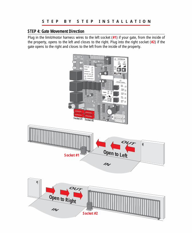
STEP 4: Gate Movement DirectionPlug in the limit/motor harness wires to the left socket (#1) if your gate, from the inside of the property, opens to the left and closes to the right. Plug into the right socket (#2) if the gate opens to the right and closes to the left from the inside of the property.
OVERLOAD
POWER
CHARGE OK
BATTERY LOW
OPEN RELAY
CLOSE RELAY
TIMERUP
ON
W1
OFF
OPEN TO RIGHT
Socket #1 Socket #2
60 0
PW
CENTRAL CONTROL
SYSTEM ON
DC OPERATOR v 5MMADE IN USA
ALARMSENSOR
REVERSESENSOR
HEAVYGATE
FIREDEPT
STRIKEOPEN
SAFETYLOOP
EXITLOOP
RADIOREC
CHARGINGPOWER
BOARDPOWER
CHECKFUSE
J2
OUT
IN
OUT
IN
Open to Right
Open to LeftSocket #1
Socket #2
OVERLOAD
POWER
BATTERY LOW
OPEN RELAY
CLOSE RELAY
TIMERUP
ON
OFF
60 0
PW
CENTRAL CONTROL
SYSTEM ON
DC OPERATOR v 5MMADE IN USA
ALARMSENSOR
REVERSESENSOR
HEAVYGATE
FIREDEPT
STRIKEOPEN
SAFETYLOOP
EXITLOOP
RADIOREC
CHARGINGPOWER
BOARDPOWER
CHECKFUSE
J2
CHARGE OKCHARGE OK
OVERLOAD
POWER
BATTERY LOW
OPEN RELAY
CLOSE RELAY
TIMERUP
ON
W1
OFF
OPEN TO RIGHT
60 0
PW
CENTRAL CONTROL
SYSTEM ON
DC OPERATOR v 5MMADE IN USA
ALARMSENSOR
REVERSESENSOR
HEAVYGATE
FIREDEPT
STRIKEOPEN
SAFETYLOOP
EXITLOOP
RADIOREC
CHARGINGPOWER
BOARDPOWER
CHECKFUSE
J2
CHARGE OK
S T E P B Y S T E P I N S T A L L A T I O N
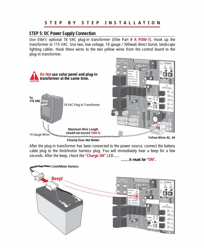
Use Elite's optional 18 VAC plug-in transformer (Elite Part # A POW-1). Hook up the transformer to 115 VAC. Use two, low voltage, 14 gauge / 300watt direct burial, landscape lighting cables. Hook these wires to the two yellow wires from the control board to the plug-in transformer.
STEP 5: DC Power Supply Connection
18 VAC Plug-in Transformer
14 Gauge Wires
Maximum Wire Length should not exceed 1000 ft.
Polarity Does Not Matter
2
135
6810
79
4
Yellow Wires #2, #4
Do Not use solar panel and plug-in transformer at the same time.
To 115 VAC
CAUTION
Beep!
After the plug-in transformer has been connected to the power source, connect the battery cable plug to the limit/motor harness plug. You will immediately hear a beep for a few seconds. After the beep, check the “Charge OK” LED......
Limit/Motor Harness
......it must be “ON”.
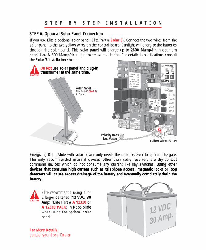
If you use Elite's optional solar panel (Elite Part # Solar 3). Connect the two wires from the solar panel to the two yellow wires on the control board. Sunlight will energize the batteries through the solar panel. This solar panel will charge up to 2800 Mamp/Hr in optimum conditions & 500 Mamp/Hr in light overcast conditions. For detailed specifications consult the Solar 3 Installation sheet.
OVERLOAD
POWER
BATTERY LOW
OPEN RELAY
CLOSE RELAY
TIMERUP
ON
W1
OFF
OPEN TO RIGHT
60 0
PW
CENTRAL CONTROL
SYSTEM ON
DC OPERATOR v 5MMADE IN USA
ALARMSENSOR
REVERSESENSOR
HEAVYGATE
FIREDEPT
STRIKEOPEN
SAFETYLOOP
EXITLOOP
RADIOREC
CHARGINGPOWER
BOARDPOWER
CHECKFUSE
J2
CHARGE OK
S T E P B Y S T E P I N S T A L L A T I O N
STEP 6: Optional Solar Panel Connection
Energizing Robo Slide with solar power only needs the radio receiver to operate the gate. The only recommended external devices other than radio receivers are dry-contact command devices which do not consume any current like key switches. Using other devices that consume high current such as telephone access, magnetic locks or loop detectors will cause excess drainage of the battery and eventually completely drain the battery .
Elite recommends using 1 or 2 larger batteries (12 VDC, 30 Amp) (Elite Part # A 12330 or A 12330 PACK) in Robo Slide when using the optional solar panel.
Polarity Does Not Matter
2
135
6810
79
4
Yellow Wires #2, #4
Do Not use solar panel and plug-in transformer at the same time.
CAUTION
CAUTION
Solar Panel(Elite Part # SOLAR 3)No Stand
30 Amp.12 VDC
For More Details,contact your Local Dealer
S T E P B Y S T E P I N S T A L L A T I O N
1 2 3 4 5 6 7 8 9 10
12 VDC Radio Receiver
Transmitters
External “Exit” Loop Detector
External “Safety” Loop Detector
Phone Entry
PushButton
CardReader
Fire orAny KeySwitch
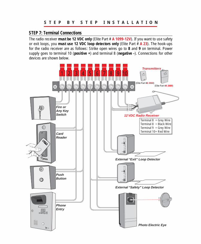
Terminal 8 = Grey WireTerminal 8 = Black WireTerminal 9 = Grey WireTerminal 10= Red Wire
4
7 8
0HELP
9
1 2 35 6
Photo Electric Eye
The radio receiver must be 12 VDC only (Elite Part # A 1099-12V). If you want to use safety or exit loops, you must use 12 VDC loop detectors only (Elite Part # A 23). The hook-ups for the radio receiver are as follows: Strike open wires go to 8 and 9 on terminal. Power supply goes to terminal 10 (positive +) and terminal 8 (negative -). Connections for other devices are shown below.
STEP 7: Terminal Connections
(Elite Part #A 3060)(Elite Part #A 3089)
TIMER UP
ON
OFF
60 0
PW
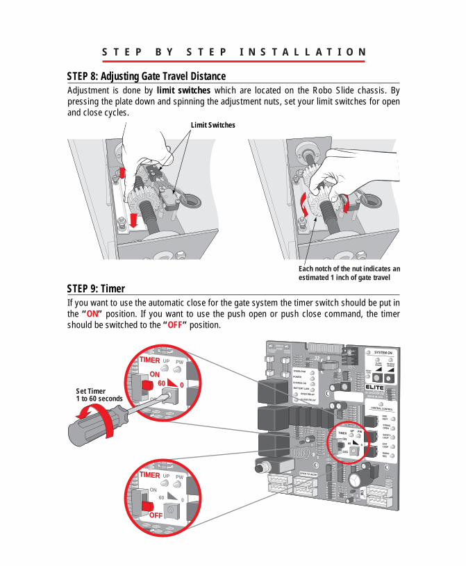
Adjustment is done by limit switches which are located on the Robo Slide chassis. By pressing the plate down and spinning the adjustment nuts, set your limit switches for open and close cycles.
S T E P B Y S T E P I N S T A L L A T I O N
STEP 8: Adjusting Gate Travel Distance
STEP 9: TimerIf you want to use the automatic close for the gate system the timer switch should be put in the “ON” position. If you want to use the push open or push close command, the timer should be switched to the “OFF” position.
Limit Switches
Each notch of the nut indicates an estimated 1 inch of gate travel
OVERLOAD
POWER
BATTERY LOW
OPEN RELAY
CLOSE RELAY
TIMERUP
ON
W1
OFF
OPEN TO RIGHT
60 0
PW
CENTRAL CONTROL
SYSTEM ON
DC OPERATOR v 5MMADE IN USA
ALARMSENSOR
REVERSESENSOR
HEAVYGATE
FIREDEPT
STRIKEOPEN
SAFETYLOOP
EXITLOOP
RADIOREC
CHARGINGPOWER
BOARDPOWER
CHECKFUSE
J2
CHARGE OK
Set Timer 1 to 60 seconds
TIMER UP
ON
OFF
60 0
PW
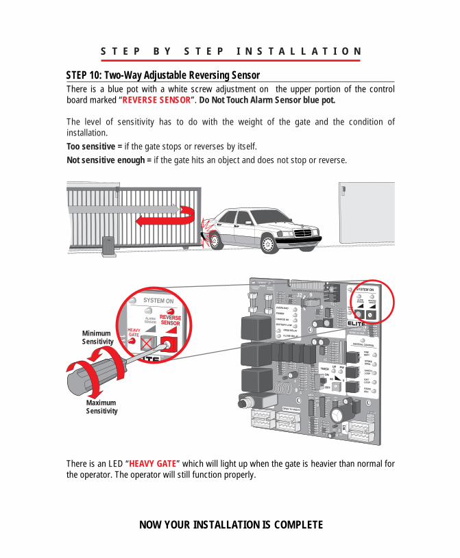
There is a blue pot with a white screw adjustment on the upper portion of the control board marked “REVERSE SENSOR”. Do Not Touch Alarm Sensor blue pot. The level of sensitivity has to do with the weight of the gate and the condition of installation.Too sensitive = if the gate stops or reverses by itself. Not sensitive enough = if the gate hits an object and does not stop or reverse.
S T E P B Y S T E P I N S T A L L A T I O N
STEP 10: Two-Way Adjustable Reversing Sensor
OVERLOAD
POWER
BATTERY LOW
OPEN RELAY
CLOSE RELAY
TIMERUP
ON
W1
OFF
OPEN TO RIGHT
60 0
PW
CENTRAL CONTROL
SYSTEM ON
DC OPERATOR v 5MMADE IN USA
ALARMSENSOR
REVERSESENSOR
HEAVYGATE
FIREDEPT
STRIKEOPEN
SAFETYLOOP
EXITLOOP
RADIOREC
CHARGINGPOWER
BOARDPOWER
CHECKFUSE
J2
CHARGE OK
SYSTEM ON
ALARMSENSOR
REVERSESENSOR
HEAVYGATE
NOW YOUR INSTALLATION IS COMPLETE
There is an LED “HEAVY GATE” which will light up when the gate is heavier than normal for the operator. The operator will still function properly.
Maximum Sensitivity
Minimum Sensitivity
OVERLOAD
POWER
BATTERY LOW
OPEN RELAY
CLOSE RELAY
CENTRAL CONTROL
SYSTEM ON
DC OPERATOR v 5MMADE IN USA
ALARMSENSOR
REVERSESENSOR
HEAVYGATE
FIREDEPT
CHARGINGPOWER
BOARDPOWER
CHECKFUSE
J2
CHARGE OK
“ O P T I O N A L ” I N P U T B O A R D
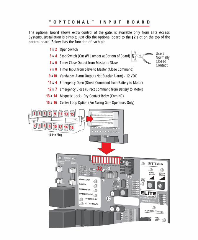
The optional board allows extra control of the gate, is available only from Elite Access Systems. Installation is simple; just clip the optional board to the J2 slot on the top of the control board. Below lists the function of each pin.
Open Switch
Stop Switch (Cut W1 Jumper at Bottom of Board)
Timer Close Output from Master to Slave
Timer Input from Slave to Master (Close Command)
Vandalism Alarm Output (Not Burglar Alarm) - 12 VDC
Emergency Open (Direct Command from Battery to Motor)
Emergency Close (Direct Command from Battery to Motor)
Magnetic Lock - Dry Contact Relay (Com NC)
Center Loop Option (For Swing Gate Operators Only)
162 4 6 8 10 12 14
15131197531
1 & 2
3 & 4
5 & 6
7 & 8
9 &10
11 & 4
12 & 7
13 & 14
15 & 16
W1
16-Pin Plug
Use a Normally Closed Contact
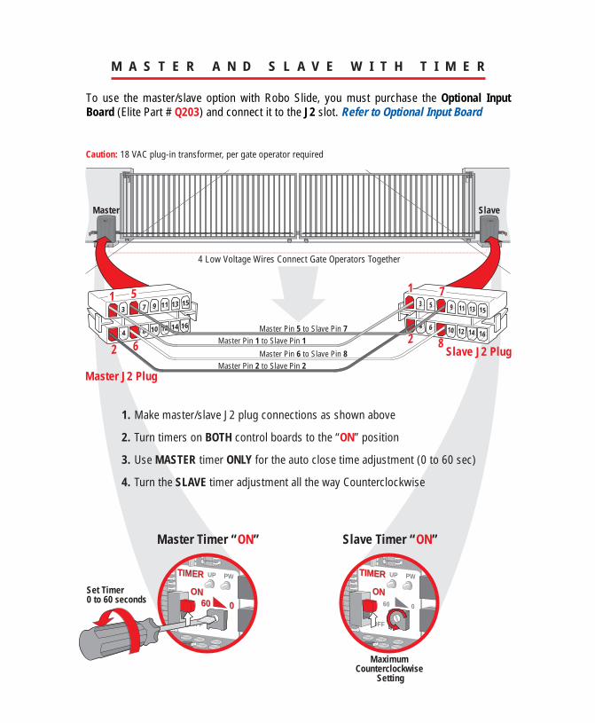
M A S T E R A N D S L A V E W I T H T I M E R
To use the master/slave option with Robo Slide, you must purchase the Optional Input Board (Elite Part # Q203) and connect it to the J2 slot. Refer to Optional Input Board
13
57 9 11 13 15
108
64
2
12 14 1616141210
864
2
1513119
753
4 Low Voltage Wires Connect Gate Operators Together
Master J2 Plug
1. Make master/slave J2 plug connections as shown above
2. Turn timers on BOTH control boards to the “ON” position
3. Use MASTER timer ONLY for the auto close time adjustment (0 to 60 sec)
4. Turn the SLAVE timer adjustment all the way Counterclockwise
Slave J2 PlugMaster Pin 1 to Slave Pin 1
Master Pin 5 to Slave Pin 7
Master Pin 6 to Slave Pin 8Master Pin 2 to Slave Pin 2
Caution: 18 VAC plug-in transformer, per gate operator required
1
TIMERTIMER UP
ONON
OFF
6060 0
PW
Master Timer “ON”
Master Slave
TIMERTIMER UP
ONON
OFF
60 0
PW
Slave Timer “ON”
Maximum Counterclockwise
Setting
Set Timer 0 to 60 seconds
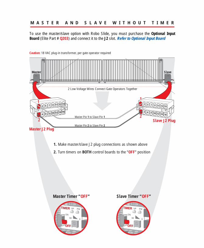
M A S T E R A N D S L A V E W I T H O U T T I M E R
To use the master/slave option with Robo Slide, you must purchase the Optional Input Board (Elite Part # Q203) and connect it to the J2 slot. Refer to Optional Input Board
13 5 7 9 11 13 15
1084 6
2
12 14 16161412106 84
2
15131195 73
2 Low Voltage Wires Connect Gate Operators Together
Master J2 Plug
1. Make master/slave J2 plug connections as shown above
2. Turn timers on BOTH control boards to the “OFF” position
Slave J2 PlugMaster Pin 1 to Slave Pin 1
Master Pin 2 to Slave Pin 2
Caution: 18 VAC plug-in transformer, per gate operator required
1
Master Timer “OFF”
Master Slave
Slave Timer “OFF”
TIMERTIMER UP
ON
OFFOFF
60 0
PW TIMERTIMER UP
ON
OFFOFF
60 0
PW
OVERLOAD
POWER
BATTERY LOW
OPEN RELAY
CLOSE RELAY
TIMERUP
ON
W1
OFF
OPEN TO RIGHT
60 0
PW
CENTRAL CONTROL
SYSTEM ON
DC OPERATOR v 5MMADE IN USA
ALARMSENSOR
REVERSESENSOR
HEAVYGATE
FIREDEPT
STRIKEOPEN
SAFETYLOOP
EXITLOOP
RADIOREC
CHARGINGPOWER
BOARDPOWER
CHECKFUSE
J2
CHARGE OK
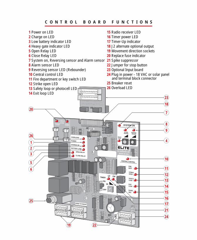
C O N T R O L B O A R D F U N C T I O N S
1 Power on LED2 Charge on LED3 Low battery indicator LED4 Heavy gate indicator LED5 Open Relay LED6 Close Relay LED7 System on, Reversing sensor and Alarm sensor8 Alarm sensor LED9 Reversing sensor LED (Rebounder)10 Central control LED11 Fire department or key switch LED12 Strike open LED13 Safety loop or photocell LED14 Exit loop LED
15 Radio receiver LED16 Timer power LED17 Timer-Up indicator18 J2 alternate optional output 19 Movement direction sockets20 Replace fuse indicator21 Spike suppressor22 Jumper for stop button23 Optional Input board 24 Plug in power - 18 VAC or solar panel and terminal block connector25 Breaker reset26 Overload LED
15141312
11
10
4
9
23
8
7
18
24
21
1716
2219
20
1
26
23
5
6
25
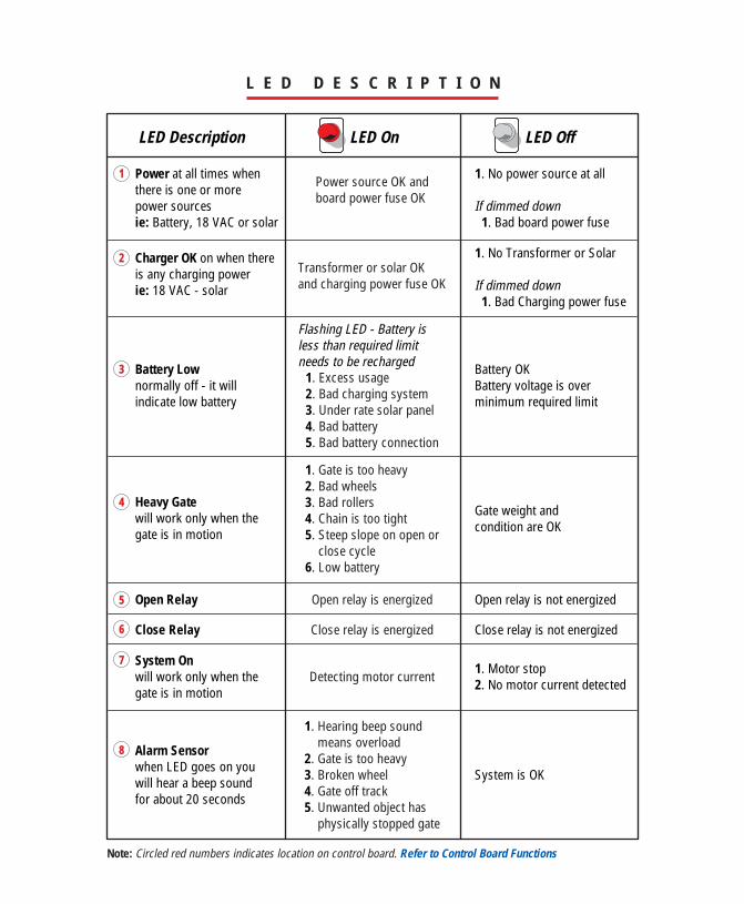
L E D D E S C R I P T I O N
Power at all times when there is one or more power sourcesie: Battery, 18 VAC or solar
Charger OK on when there is any charging powerie: 18 VAC - solar
Battery Lownormally off - it willindicate low battery
System Onwill work only when thegate is in motion
Alarm Sensorwhen LED goes on youwill hear a beep soundfor about 20 seconds
Heavy Gatewill work only when thegate is in motion
Open Relay Open relay is not energized
1. No power source at all If dimmed down 1. Bad board power fuse
1. No Transformer or Solar If dimmed down 1. Bad Charging power fuse
1. Motor stop2. No motor current detected
Battery OKBattery voltage is over minimum required limit
Gate weight andcondition are OK
System is OK
Open relay is energized
Flashing LED - Battery isless than required limit needs to be recharged
Power source OK andboard power fuse OK
Transformer or solar OKand charging power fuse OK
1. Excess usage2. Bad charging system3. Under rate solar panel4. Bad battery5. Bad battery connection
1. Hearing beep sound means overload2. Gate is too heavy3. Broken wheel4. Gate off track5. Unwanted object has physically stopped gate
1. Gate is too heavy2. Bad wheels3. Bad rollers4. Chain is too tight5. Steep slope on open or close cycle6. Low battery
Close Relay Close relay is not energizedClose relay is energized
Detecting motor current
Note: Circled red numbers indicates location on control board. Refer to Control Board Functions
1
2
3
5
6
7
8
4
LED Description LED On LED Off
L E D D E S C R I P T I O N - C O N T I N U E D
LED Description LED On LED Off
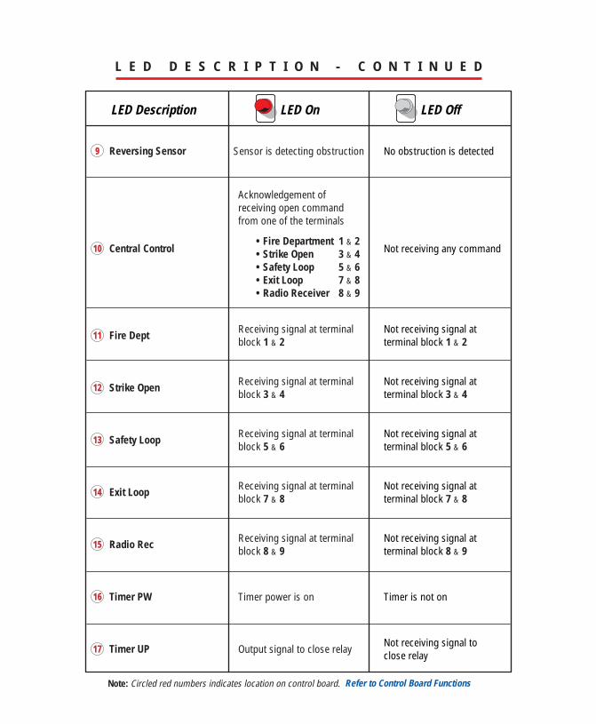
Note: Circled red numbers indicates location on control board.
9 Reversing Sensor No obstruction is detectedSensor is detecting obstruction
11 Fire Dept Receiving signal at terminalblock 1 & 2
Not receiving signal atterminal block 1 & 2
10 Central Control Not receiving any command
Acknowledgement ofreceiving open commandfrom one of the terminals
• Fire Department 1 & 2• Strike Open 3 & 4• Safety Loop 5 & 6 • Exit Loop 7 & 8• Radio Receiver 8 & 9
12 Strike Open Receiving signal at terminalblock 3 & 4
Not receiving signal atterminal block 3 & 4
13 Safety Loop Receiving signal at terminalblock 5 & 6
Not receiving signal atterminal block 5 & 6
14 Exit Loop Receiving signal at terminalblock 7 & 8
Not receiving signal atterminal block 7 & 8
15 Radio Rec Receiving signal at terminalblock 8 & 9
Not receiving signal atterminal block 8 & 9
17 Timer UP Output signal to close relay Not receiving signal toclose relay
16 Timer PW Timer power is on Timer is not on
Refer to Control Board Functions
OVERLOAD
POWER
BATTERY LOW
OPEN RELAY
CLOSE RELAY
DC OPEMAD
HEAVYGATE
CHARGINGPOWER
BOARDPOWER
CHECKFUSE
J2
CHARGE OK
OPEN TO RIGHT
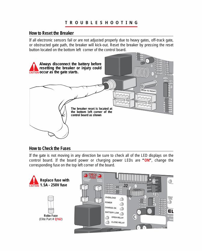
If the gate is not moving in any direction be sure to check all of the LED displays on the control board. If the board power or charging power LEDs are “ON”, change the corresponding fuse on the top left corner of the board.
T R O U B L E S H O O T I N G
If all electronic sensors fail or are not adjusted properly due to heavy gates, off-track gate, or obstructed gate path, the breaker will kick-out. Reset the breaker by pressing the reset button located on the bottom left corner of the control board.
How to Reset the Breaker
How to Check the Fuses
CAUTION
CAUTION
Always disconnect the battery before resetting the breaker or injury could occur as the gate starts.
The breaker reset is located at the bottom left corner of the control board as shown
Replace fuse with 1.5A - 250V fuse
(Elite Part # Q162)Robo Fuse
0
PW
CENTRAL CONTROL
DC OPERATOR v 5MMADE IN USA
FIREDEPT
STRIKEOPEN
SAFETYLOOP
EXITLOOP
RADIOREC
T R O U B L E S H O O T I N G
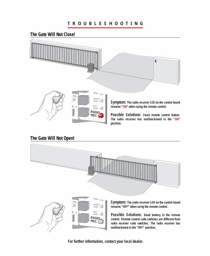
The Gate Will Not Close!
Symptom: The radio receiver LED on the control board remains “ON” when using the remote control.
Possible Solutions: Stuck remote control button. The radio receiver has malfunctioned in the “ON” position.
0
PW
CENTRAL CONTROL
DC OPERATOR v 5MMADE IN USA
FIREDEPT
STRIKEOPEN
SAFETYLOOP
EXITLOOP
RADIOREC
The Gate Will Not Open!
Symptom: The radio receiver LED on the control board remains “OFF” when using the remote control.
Possible Solutions: Dead battery in the remote control. Remote control code switches are different from radio receiver code switches. The radio receiver has malfunctioned in the “OFF” position.
For further information, contact your local dealer.
T R O U B L E S H O O T I N G a n d P A R T S L I S T
Multiple Parts “Q” Number
A BT 12 - 12 VDC, 7 amp. Battery with HarnessA H-110 - Gate Chain #41 (10 ft) (20 ft included)A H-111 - Gate Chain #40 (10 ft) OptionalA H-113 - Master LinkA H-125 - Master LinkQ003 - Chain BoltQ004 - Chain BracketQ006 - PC Board Nuts (1 Set)Q029 - Limit SwitchQ032 - Limit Switch Adjustment NutQ101 - Limit Switch Bearing HolderQ123 - Motor - DC - 12V
Robo Slide Conversion Kit
Q204
Q211 - Limit/Motor HarnessQ218 - Terminal HarnessQ206 - Control BoardBattery Harness
Q124 - ChassisQ129 - Idler Sprocket with Bolt/NutQ131 - Limit Switch Drive SprocketQ132 - Limit Switch SprocketQ133 - Drive SprocketQ135 - Limit Switch Bolt (Shaft)Q137 - Limit Switch BoxQ156 - 1/2 Inch CollarQ162 - FuseQ180 - 1 inch Diameter CouplingQ203 - Option Board with HarnessQ206 - Control BoardQ211 - Limit/Motor HarnessQ212 - Gear Reducer 40 - 30:1Q218 - Terminal HarnessQ241 - Cover, Polyethylene Plastic
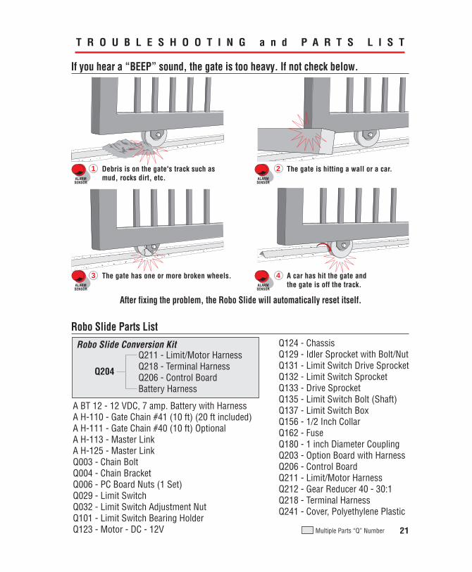
If you hear a “BEEP” sound, the gate is too heavy. If not check below.
Robo Slide Parts List
The gate is hitting a wall or a car.21 Debris is on the gate's track such as mud, rocks dirt, etc.ALARM
SENSORALARMSENSOR
ALARMSENSOR
ALARMSENSOR
The gate has one or more broken wheels. A car has hit the gate and the gate is off the track.
43
After fixing the problem, the Robo Slide will automatically reset itself.
21
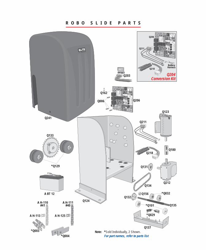
Note: *Sold Individually, 2 Shown.For part names, refer to parts list
R O B O S L I D E P A R T S
Q241
OVERLOAD
POWER
CHARGE OK
BATTERY LOW
OPEN RELAY
CLOSE RELAY
TIMERUP
ON
W1
OFF
OPEN TO RIGHT
60 0
PW
CENTRAL CONTROL
SYSTEM ON
DC OPERATOR v 5MMADE IN USA
ALARMSENSOR
REVERSESENSOR
HEAVYGATE
FIREDEPT
STRIKEOPEN
SAFETYLOOP
EXITLOOP
RADIOREC
CHARGINGPOWER
BOARDPOWER
CHECKFUSE
J2
*Q004
*Q003
Q006
Q162
Q203
Q206
Q211
Q206
Q218BatteryHarness
Q204Conversion Kit
Q134
Q133
Q132
Q131
Q218
Q211
Q212
Q180
Q123
*Q129
Q124
A BT 12
A H-110#41
A H-113 A H-125
A H-111#40
*Q029
Q137
Q135
Q156 *Q032
*Q101
OVERLOAD
POWER
CHARGE OK
BATTERY LOW
OPEN RELAY
CLOSE RELAY
TIMERUP
ON
W1
OFF
OPEN TO RIGHT
60 0
PW
CENTRAL CONTROL
SYSTEM ON
DC OPERATOR v 5MMADE IN USA
ALARMSENSOR
REVERSESENSOR
HEAVYGATE
FIREDEPT
STRIKEOPEN
SAFETYLOOP
EXITLOOP
RADIOREC
CHARGINGPOWER
BOARDPOWER
CHECKFUSE
J2