Embed Size (px)
Citation preview

RF SCOUT PLUS INSTRUCTION MANUAL
Dielectric, LLC
22 Tower Rd.
Raymond, ME 04071
Phone: 800.341.9678
www.dielectric.com
21 January 2015, Rev B 1

21 January 2015, Rev B 2
WARNING
Powering RF sensors above +30dBm (1W) will cause failure
If existing directional couplers are used for the RF scout, ensure that the coupling charts are
consulted for the line power level. Use total combined power for coupling value when multiple
channels are present on the line.
Directional couplers should be set to the value on the provided chart. To ensure accurate
measurements, the directional couplers should have a minimum of 30 dB directivity.
RF Scout "Ideal Coupling Levels" to give +20dBm at the sensor input for Forward Power.
Power Level (kW) Forward Coupling Reflected Coupling
100 -60.00 -50.00
90 -59.54 -49.54
80 -59.03 -49.03
70 -58.45 -48.45
60 -57.78 -47.78
50 -56.99 -46.99
45 -56.53 -46.53
40 -56.02 -46.02
35 -55.44 -45.44
30 -54.77 -44.77
25 -53.98 -43.98
20 -53.01 -43.01
15 -51.76 -41.76
10 -50.00 -40.00
5 -65.99 -55.99
2 -62.01 -52.01
1 -59.00 -49.00
21 January 2015, Rev B 3
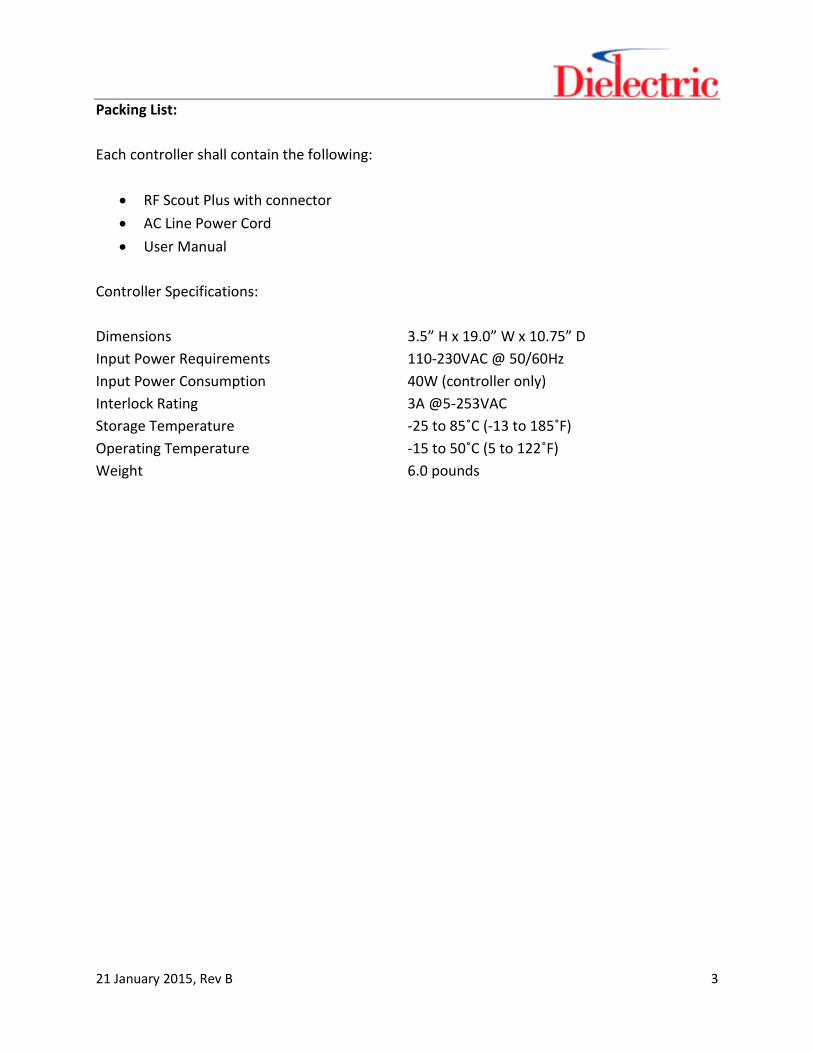
Packing List:
Each controller shall contain the following:
RF Scout Plus with connector
AC Line Power Cord
User Manual
Controller Specifications:
Dimensions 3.5” H x 19.0” W x 10.75” D
Input Power Requirements 110-230VAC @ 50/60Hz
Input Power Consumption 40W (controller only)
Interlock Rating 3A @5-253VAC
Storage Temperature -25 to 85˚C (-13 to 185˚F)
Operating Temperature -15 to 50˚C (5 to 122˚F)
Weight 6.0 pounds

21 January 2015, Rev B 4
Table of Contents
Table of Contents 4
Table of Tables 5
Table of Figures 6
Introduction 7
1 Setup 8
2 Installation 9
2.1 Coupler Placement 9
2.2 RF Power Sensors 9
2.3 Signal Selection 10
2.4 Rack Mount Module 10
2.4.1 Front Panel 10
2.4.2 Rear Panel 11
3 Operation 13
3.1 Touch Screen Interface 13
3.1.1 Sensor Readings 14
3.1.2 Alarm Status 14
3.1.3 Setup Menu 15
3.1.4 System Settings 21
3.2 Web Interface 27
21 January 2015, Rev B 5
Table of Tables
Table 1.1 – Parameters as Shipped 8
Table 2.1 – Connector Description 11
Table 3.1 – Main Menu Functions 14
Table 3.2 – Sensor Readings 14
Table 3.3 – Alarm Status Functions 15
Table 3.4 – Setup Functions 15
Table 3.5 – Forward Coupler Configuration Functions 16
Table 3.6 – Reflected Coupler Configuration Functions 17
Table 3.7 – Alarm Setpoint Functions 18
Table 3.8 – VSWR Alarm Setpoint Functions 19
Table 3.9 – Forward Power Alarm Setpoint Functions 19
Table 3.10 – Temperature Alarm Setpoint Functions 20
Table 3.11 – Pressure Alarm Setpoint Functions 20
Table 3.12 – System Settings Menu Functions 21
Table 3.13 – Clock Functions 22
Table 3.14 – Signal Type Functions 22
Table 3.15 – Network Functions 23
Table 3.16 – Sensor Functions 24

21 January 2015, Rev B 6
Table of Figures
Figure 2.1 – RF Scout Plus Front Panel 10
Figure 2.2 – RF Scout Plus Rear Panel 11
Figure 2.3 – Typical Wiring Diagram 12
Figure 3.1 – RF Scout Plus Main Screen 13
Figure 3.2 – Menu Flow Block Diagram 13
Figure 3.3 – Alarm Status Screen 14
Figure 3.4 – Setup Menu 15
Figure 3.5 – Forward Coupler Menu 16
Figure 3.6 – Reflected Coupler Menu 16
Figure 3.7 – Alarm Setpoints Menu 17
Figure 3.8 – VSWR Alarm Setpoints 18
Figure 3.9 – Forward Power Alarm Setpoints 19
Figure 3.10 – Temperature Alarm Setpoints 20
Figure 3.11 – Pressure Alarm Setpoints 20
Figure 3.12 – System Menu 21
Figure 3.13 – Clock Menu 21
Figure 3.14 – Signal Type Menu 22
Figure 3.15 – Network Menu 23
Figure 3.16 – Sensors Menu 24
Figure 3.17 – RF Scout Plus Website 25

21 January 2015, Rev B 7
Introduction
The Dielectric RF Scout monitors RF transmission system VSWR and forward power and is
designed to aid in detecting VSWR problems as they develop. In many cases this will allow the
transmitter operator to detect and remedy transmission system issues which may be
contributing to elevated VSWR before they affect operations. The unit continuously monitors
line forward and reflected power and utilizes a logic controller in order to calculate VSWR. The
system displays the values and can store data and alarms in internal memory. User settable
alarm levels are accessible for all alarms. Additionally, the system can be configured to monitor
transmission line pressure and temperature.
The RF Scout monitoring and communications capabilities offer a high degree of flexibility. The
unit’s status is available to local operators via the front panel touch-screen interface. Also, the
data is available to remote terminals via an Ethernet interface with FTP or HTTP. There are also
points for remote monitoring available on the rear connector.

21 January 2015, Rev B 8
1 Setup
The RF Scout is configured at the factory with default values for the calibration factors, alarm
limits and interface settings. In some instances the pre-configured values may suit the
particular system it is going into; however, it is necessary for the installer to ensure that all
pertinent calibration values are set properly after the system is installed. This includes the
sensor calibration factors, coupling factors and alarm limits. Additionally, the operator should
ensure that the proper IP address, date, and time are entered.
Setting Shipped Value Unit
Forward Coupling 50 dBm
Forward Offset 0.35 V
Forward 20 dBm 2.0 V
Reflected Coupling 40 dBm
Reflected Offset 0.35 V
Reflected 20 dBm 2.0 V
Power Sensor Type Standard -
Pressure Sensor Sensor OFF -
Temperature Sensor Sensor OFF - Table 1.1 – Parameters as Shipped

21 January 2015, Rev B 9
2 Installation
RF Scout Monitoring System installation has been designed to be as simple as possible. The
system is comprised of:
(i) Dual directional coupler for appropriate waveguide or coax line size
(ii) Tru Power sensors, Dielectric Part No. R97730 or Low Power Sensor Part No. 11000005351
(for use below 5kW)
(iii) Sensor cables
(iv) RF Scout Rack Mount module
(v) Optional pressure sensor, Dielectric Part No. R78740
(vi) Optional temperature sensor, Dielectric Part No. 11000005843
2.1 Coupler Placement
The dual directional coupler has to be inserted into the line to be monitored. Ensure that the
coupler orientation is such that the forward and reverse coupling ports are set up correctly.
It is essential that the power flow through the coupler is in the appropriate direction. At the
time of installation note the forward and reverse coupling values as these are required for
accurate calibration of the RF Scout monitoring system. For optimum accuracy, the coupling
levels are routinely set to provide a +20dBm signal to the forward power sensor under normal
operating power levels.
2.2 RF Power Sensors
The RF power sensors supplied with the RF Scout system have been calibrated at the factory to
ensure system accuracy. The sensor units include a type N (male) connector for connection to
the directional coupler ports on the line to be monitored. There is also a 3-pin D-sub connector
to facilitate connection of the cabling between the sensor and the rack mount module. The rack
mount module supplies a ground and +24V to the sensor. The output signal from the sensor
corresponding to the measured power level is then relayed back to the rack mount module
using the other pin available.
The maximum input power level to the sensor must not exceed 1W (30dBm).
21 January 2015, Rev B 10
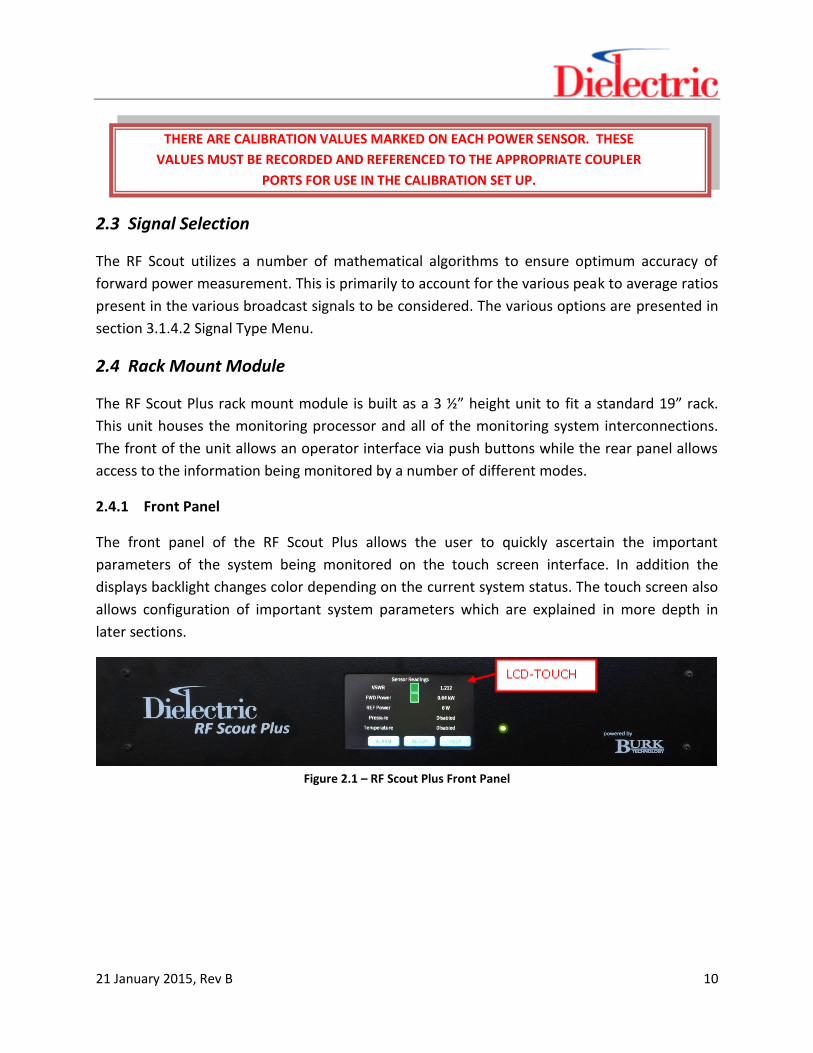
THERE ARE CALIBRATION VALUES MARKED ON EACH POWER SENSOR. THESE
VALUES MUST BE RECORDED AND REFERENCED TO THE APPROPRIATE COUPLER
PORTS FOR USE IN THE CALIBRATION SET UP.
2.3 Signal Selection
The RF Scout utilizes a number of mathematical algorithms to ensure optimum accuracy of
forward power measurement. This is primarily to account for the various peak to average ratios
present in the various broadcast signals to be considered. The various options are presented in
section 3.1.4.2 Signal Type Menu.
2.4 Rack Mount Module
The RF Scout Plus rack mount module is built as a 3 ½” height unit to fit a standard 19” rack.
This unit houses the monitoring processor and all of the monitoring system interconnections.
The front of the unit allows an operator interface via push buttons while the rear panel allows
access to the information being monitored by a number of different modes.
2.4.1 Front Panel
The front panel of the RF Scout Plus allows the user to quickly ascertain the important
parameters of the system being monitored on the touch screen interface. In addition the
displays backlight changes color depending on the current system status. The touch screen also
allows configuration of important system parameters which are explained in more depth in
later sections.
Figure 2.1 – RF Scout Plus Front Panel

21 January 2015, Rev B 11
2.4.2 Rear Panel
The rear panel of the unit provides spring-clamp style connections for all monitoring equipment
as well as a RJ-45 connection for Ethernet connectivity. Additionally there is a standard PC
power plug connection for incoming AC power. The remote connections provide a 24VDC signal
when the corresponding alarm is active. Providing a 24VDC input to the RESET pin will reset a
strikeout situation in the system.
Figure 2.2 – RF Scout Plus Rear Panel
Pin Label Description
1 RTD WHT 3-Wire RTD White Lead
2 RTD RED 3-Wire RTD Red Lead
3 RTD RED 3-Wire RTD Red Lead
4 RTD SHLD 3-Wire RTD Shield (If applicable)
5 +24V +24VDC for remote application
6 -V DC Common for remote application
7 REMOTE INTLK +24VDC available at this pin when interlock is energized
8 REMOTE VSWR +24VDC available at this pin when VSWR alarm exists
9 REMOTE FWD +24VDC available at this pin when forward power alarm exists
10 REMOTE PRESS +24VDC available at this pin when pressure alarm exists
11 REMOTE RESET Provide +24VDC to this pin to reset VSWR strikeout
12 REMOTE –V DC Common for remote application
13 FWD +24V +24VDC for forward power sensor supply
14 FWD –V DC Common for forward power sensor supply
15 FWD SIG Signal return from forward power sensor
16 REF +24V +24VDC for reflected power sensor supply
17 REF –V DC Common for reflected power sensor supply
18 REF SIG Signal return from reflected power sensor
19 PRESS +24V +24VDC for pressure sensor supply
20 PRESS –V DC Common for pressure sensor supply (for non-loop powered sensor)
21 PRESS SIG Signal return from pressure sensor
22 INTLK NO Normally open transmitter interlock contact
23 INTLK COM Common transmitter interlock contact
24 INTLK NC Normally closed transmitter interlock contact
- LAN Local Area Network access at the IP address set
- 120-240 VAC Incoming power 100-240VAC at 50/60Hz
Table 2.1 – Connector Description

21 January 2015, Rev B 12
Figure 2.3 – Typical Wiring Diagram
21 January 2015, Rev B 13
3 Operation
The RF Scout Plus provides two ways for the operator to view the system. First, all values can be
set and observed via the touch screen interface. Additionally, the RF Scout Plus utilizes a
website to allow remote viewing of alarms, history of the unit, and the ability to reset a VSWR
strikeout.
3.1 Touch Screen Interface
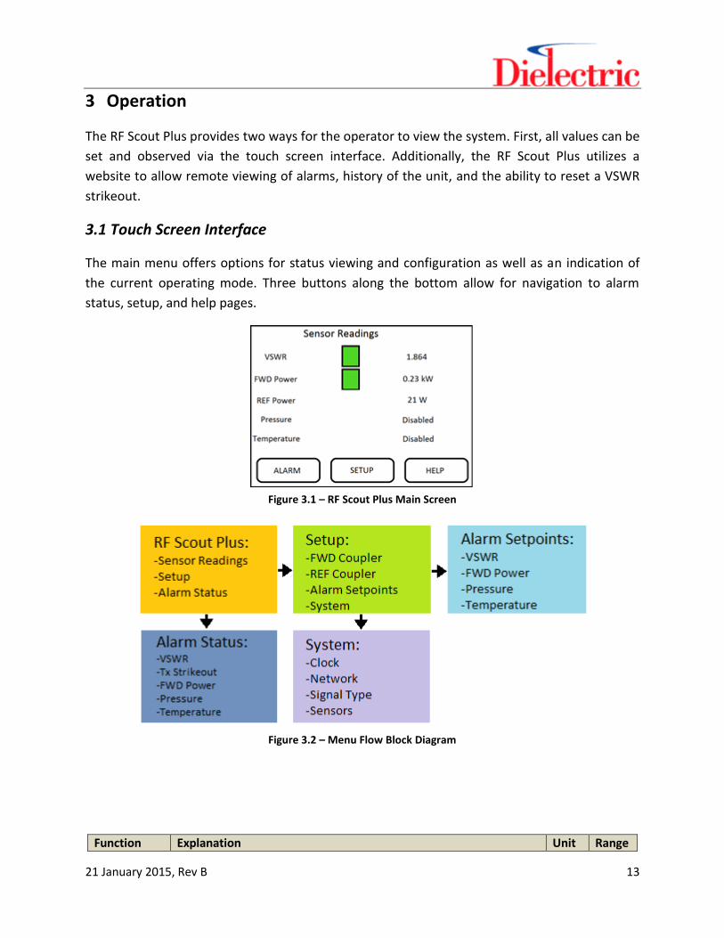
The main menu offers options for status viewing and configuration as well as an indication of
the current operating mode. Three buttons along the bottom allow for navigation to alarm
status, setup, and help pages.
Figure 3.1 – RF Scout Plus Main Screen
Figure 3.2 – Menu Flow Block Diagram
Function Explanation Unit Range

21 January 2015, Rev B 14
Sensor Readings
Displayed on main screen - -
Alarm Status Changes screen to show current alarm status, when selected - -
Setup Changes screen to allow setup changes, when selected - - Table 3.1 – Main Menu Functions
3.1.1 Sensor Readings
Five sensor readings are available on the main screen in all RF Scout Plus units: VSWR, forward
power, reflected power, pressure and temperature.
Function Explanation Unit Range
VSWR VSWR reading - 1-2
FWD Power Forward Power reading kW 0-50
REF Power Reflected Power reading W 0-200
Pressure Pressure reading (if enabled) psi -
Temperature Temperature Reading (if enabled) ˚F - Table 3.2 – Sensor Readings
3.1.2 Alarm Status
The alarm status screen, accessed by pressing the “Alarm” button from the main screen,
provides quick viewing of the current alarm status of the system. When the box to the right of
the title is illuminated, the alarm is active. If the Tx Strikeout alarm is active, it requires user
intervention to clear. This can be accomplished by pressing the “RESET” button on the page.
Figure 3.3 Alarm Status Screen
Function Explanation Unit Range
VSWR Alarm VSWR Alarm Status - -
Tx Strikeout Transmitter Strikeout Status - -

21 January 2015, Rev B 15
FWD Power FWD Power Alarm Status - -
Pressure Pressure Alarm Status - -
Temperature Temperature Alarm Status - -
HOME Select to return to the main screen - -
RESET Select to reset a Transmitter Strikeout condition - -
HELP Select for help using the screen - - Table 3.3 – Alarm Status Functions
3.1.3 Setup Menu
The setup screen, accessed by pressing the “Setup” button from the main screen, provides the
ability to set various system parameters. The configuration parameters have been broken into
multiple categories for easier access.
Figure 3.4 – Setup Menu
Function Explanation Unit Range
FWD Coupler Changes screen to show and adjust FWD coupler settings (coupling, offset, 20dBm voltage), when selected
- -
REF Coupler Changes screen to show and adjust REF coupler settings (coupling, offset, 20dBm voltage), when selected
Alarm Setpoints Changes screen to show and adjust alarm setpoints, when selected - -
System Changes screen to show and adjust system settings, when selected - -
HOME Select to return to the main screen - -
HELP Select for help using the screen - - Table 3.4 – Setup Functions
3.1.3.1 Coupler Configuration
The coupler configuration screens, accessed by pressing the “FWD Coupler” or “REF Coupler”
buttons from the setup menu, allows input of the calibration factors for the Dielectric RF Power

21 January 2015, Rev B 16
sensors. The coupling value should be entered as a positive value (-60dBm should be entered as
60.00). To enter the values, the user simply touches the value to be changed and enters the
new value on the keyboard that pops-up.
Figure 3.5 – Forward Coupler Menu
Function Explanation Unit Range
FWD Coupler Forward Power Sensor coupling value (inverted) dBm 0-70
FWD Offset Forward Power Sensor offset voltage V 0-1
FWD 20dBm Forward Power Sensor Voltage at 20dBm V 0-3
Power Sensor Type
Type of power sensor to be used, either “Standard” or “Low Power” - -
HOME Select to return to the main screen - -
HELP Select for help using the screen - - Table 3.5 – Forward Coupler Configuration Functions
Figure 3.6 – Reflected Coupler Menu
Function Explanation Unit Range
REF Coupler Reflected Power Sensor coupling value (inverted) dBm 0-70
REF Offset Reflected Power Sensor offset voltage V 0-1
REF 20dBm Reflected Power Sensor Voltage at 20dBm V 0-3

21 January 2015, Rev B 17
THERE ARE CALIBRATION VALUES MARKED ON EACH POWER SENSOR. THESE
VALUES MUST BE RECORDED AND REFERENCED TO THE APPROPRIATE COUPLER
PORTS FOR USE IN THE CALIBRATION SET UP.
Power Sensor Type
Type of power sensor to be used, either “Standard” or “Low Power” - -
HOME Select to return to the main screen - -
HELP Select for help using the screen - - Table 3.6 – Reflected Coupler Configuration Functions
3.1.3.2 Alarm Setpoints Menu
The alarm setpoints screens, accessed by pressing the “Alarm Setpoints” button on the setup
screen, allows the operator to adjust alarm levels for the various system alarms. The first page
provides selection of the various setpoints.
Figure 3.7 – Alarm Setpoints Menu
Function Explanation Unit Range
VSWR Minor Adjust Minor VSWR alarm setpoint, when selected - -
VSWR Major Adjust Major VSWR alarm setpoint, when selected - -
Low Fwd PWR
Adjust Low Forward Power alarm setpoint, when selected - -
High Fwd Adjust High Forward Power alarm setpoint, when selected - -
21 January 2015, Rev B 18
Power
Low Pressure Adjust Low Pressure alarm setpoint, when selected - -
High Pressure
Adjust High Pressure alarm setpoint, when selected - -
Low Temp Adjust Low Temperature alarm setpoint, when selected - -
High Temp Adjust High Temperature alarm setpoint, when selected - -
HOME Select to return to the main screen - -
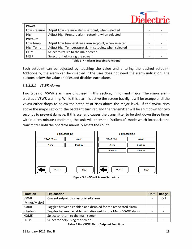
HELP Select for help using the screen - - Table 3.7 – Alarm Setpoint Functions
Each setpoint can be adjusted by touching the value and entering the desired setpoint. Additionally, the alarm can be disabled if the user does not need the alarm indication. The buttons below the value enables and disables each alarm.
3.1.3.2.1 VSWR Alarms
Two types of VSWR alarm are discussed in this section, minor and major. The minor alarm
creates a VSWR warning. While this alarm is active the screen backlight will be orange until the
VSWR either drops to below the setpoint or rises above the major level. If the VSWR rises
above the major setpoint, the backlight turn red and the transmitter will be shut down for two
seconds to prevent damage. If this scenario causes the transmitter to be shut down three times
within a ten minute timeframe, the unit will enter the “strikeout” mode which interlocks the
transmitter until the operator manually resets the count.
Figure 3.8 – VSWR Alarm Setpoints
Function Explanation Unit Range
VSWR (Minor/Major)
Current setpoint for associated alarm - 0-2
Alarm Toggles between enabled and disabled for the associated alarm. - -
Interlock Toggles between enabled and disabled for the Major VSWR alarm - -
HOME Select to return to the main screen - -
HELP Select for help using the screen - - Table 3.8 – VSWR Alarm Setpoint Functions

21 January 2015, Rev B 19
3.1.3.2.2 RF Power Alarms
High and low setpoints for forward power, pressure, and temperature are provided on the
other screens from the alarm setpoints menu.
Figure 3.9 – Forward Power Alarm Setpoints
Function Explanation Unit Range
Fwd Power (Low/High)
Current setpoint for associated alarm. kW 0-100
Alarm Toggles between enabled and disabled for the associated alarm. - -
HOME Select to return to the main screen - -
HELP Select for help using the screen - - Table 3.9 – Forward Power Alarm Setpoint Functions

21 January 2015, Rev B 20
3.1.3.2.3 Temperature Alarms
Figure 3.10 – Temperature Alarm Setpoints
Function Explanation Unit Range
Temperature (Low/High)
Current setpoint for associated alarm. ˚F 0-999
Alarm Toggles between enabled and disabled for the associated alarm. - -
HOME Select to return to the main screen - -
HELP Select for help using the screen - - Table 3.10 – Temperature Alarm Setpoint Functions
3.1.3.2.4 Pressure Alarms
Figure 3.11 – Pressure Alarm Setpoints
Function Explanation Unit Range
Pressure (Low/High)
Current setpoint for associated alarm. psi 0-99
Alarm Toggles between enabled and disabled for the associated alarm. - -
HOME Select to return to the main screen - -
HELP Select for help using the screen - - Table 3.11 – Pressure Alarm Setpoint Functions
21 January 2015, Rev B 21
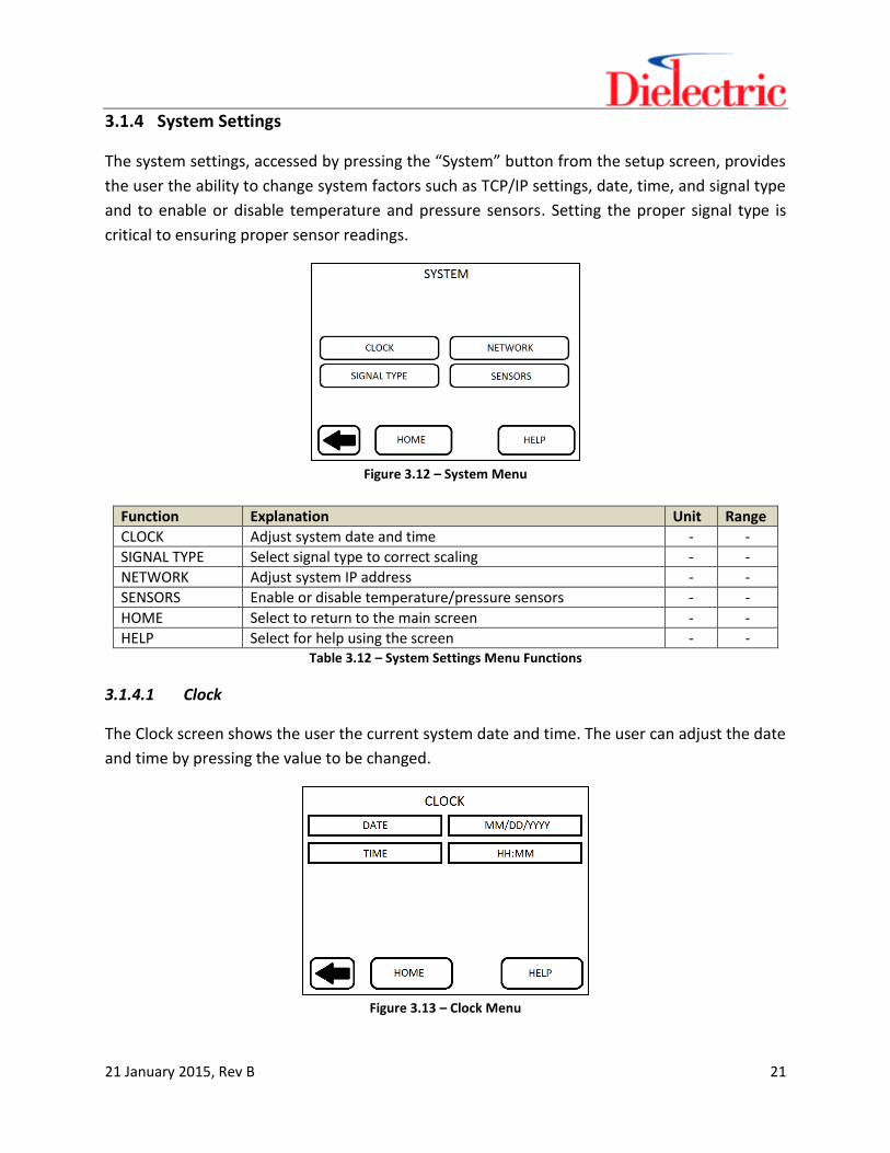
3.1.4 System Settings
The system settings, accessed by pressing the “System” button from the setup screen, provides
the user the ability to change system factors such as TCP/IP settings, date, time, and signal type
and to enable or disable temperature and pressure sensors. Setting the proper signal type is
critical to ensuring proper sensor readings.
Figure 3.12 – System Menu
Function Explanation Unit Range
CLOCK Adjust system date and time - -
SIGNAL TYPE Select signal type to correct scaling - -
NETWORK Adjust system IP address - -
SENSORS Enable or disable temperature/pressure sensors - -
HOME Select to return to the main screen - -
HELP Select for help using the screen - - Table 3.12 – System Settings Menu Functions
3.1.4.1 Clock
The Clock screen shows the user the current system date and time. The user can adjust the date
and time by pressing the value to be changed.
Figure 3.13 – Clock Menu

21 January 2015, Rev B 22
Function Explanation Unit Range
Date Shows current date - -
Time Shows current time - -
HOME Select to return to the main screen - -
HELP Select for help using the screen - - Table 3.13 – Clock Functions
3.1.4.2 Signal Type
The signal type screen allows the user to select the type of signal in the line being monitored.
This is necessary for the unit to perform correct math and ensure accurate readings. Enter the
value corresponding with the signal type in the system. The current signal is highlighted and
displayed at the top of the screen.
Figure 3.14 – Signal Type Menu
Function Explanation Unit Range
DTV Digital Television Signal - -
NTSC Analog Television Signal - -
Analog FM Analog FM Signal - -
Digital FM Analog FM w/ IBOC injected - -
IBOC IBOC-FM Signal - -
CW Continuous Wave Signal - -
HOME Select to return to the main screen - -
HELP Select for help using the screen - - Table 3.14 – Signal Type Functions

21 January 2015, Rev B 23
3.1.4.3 Network
The IP setting page allows the user to adjust all IP values to allow network interoperability. This
value will be the address that the unit can be connected to for web based control.
The default values are:
IP: 192.168.0.100
Subnet: 255.255.255.0
Gateway: 192.168.0.1
These settings are all user adjustable. Each value may be adjusted be choosing the value and
typing in the new value using the pop-up keyboard. After making the necessary changes push
the ENTER command, then return to the main screen by pressing HOME. This will ensure that
the new IP address has been changed and will be retained, even after loss of power.
Figure 3.15 – Network Menu
Function Explanation Unit Range
IP ADDRESS Change IP address - -
SUBNET Change subnet - -
GATEWAY Change gateway - -
HTTP Port Change http port - -
HOME Select to return to the main screen - -
HELP Select for help using the screen - -
Table 3.15 – Network Functions

21 January 2015, Rev B 24
3.1.4.4 Sensors
The sensors button, accessed from the system menu, allows a user to enable or disable the
optional temperature and/or pressure sensor.
Figure 3.16 – Sensors Menu
Function Explanation Unit Range
PRESSURE SENSOR
Enable/disable pressure sensor - -
TEMPERATURE SENSOR
Enable/disable temperature sensor - -
HOME Select to return to the main screen - -
HELP Select for help using the screen - -
Table 3.16 – Sensor Functions
3.2 Web Interface
The RF Scout Plus incorporates a website that can be viewed from any standard web browser
with Java Runtime. The website is accessed by pointing your browser to the units IP address.
This will initialize the Java applet and show the website. Any computer with network
capabilities and the Java Runtime can view the website.
To view the webpage a few guidelines must be followed:
1) The units Subnet and Gateway (accessed through the Network menu) must match
those of the computer trying to access the RF Scout Plus.
2) The IP address of the RF Scout Plus must be changed from the default setting to a
free IP address on the user’s network.
3) Users must log in to view the website, the default username and password are
“admin” and “password” respectively.
21 January 2015, Rev B 25
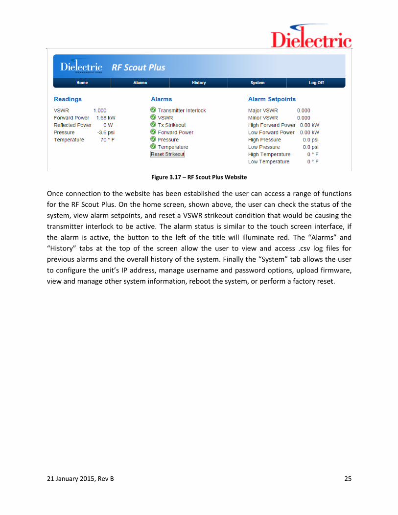
Figure 3.17 – RF Scout Plus Website
Once connection to the website has been established the user can access a range of functions
for the RF Scout Plus. On the home screen, shown above, the user can check the status of the
system, view alarm setpoints, and reset a VSWR strikeout condition that would be causing the
transmitter interlock to be active. The alarm status is similar to the touch screen interface, if
the alarm is active, the button to the left of the title will illuminate red. The “Alarms” and
“History” tabs at the top of the screen allow the user to view and access .csv log files for
previous alarms and the overall history of the system. Finally the “System” tab allows the user
to configure the unit’s IP address, manage username and password options, upload firmware,
view and manage other system information, reboot the system, or perform a factory reset.