Embed Size (px)
Citation preview
1PRINTED IN THE U.S.A 1203 PART NO. 184671-000
KEEP THIS MANUAL IN THE POCKET ON HEATER FOR FUTURE REFERENCEWHEN EVER MAINTENANCE ADJUSTMENT OR SERVICE IS REQUIRED.
ALL TECHNICAL AND WARRANTY QUESTIONS: SHOULD BE DIRECTED TO THE LOCAL DEALER FROM WHOM THE WATER HEATER WASPURCHASED. IF YOU ARE UNSUCCESSFUL, PLEASE WRITE TO THE COMPANY LISTED ON THE RATING PLATE ON THE WATER HEATER.
GAMA certification applies to allresidential electric water heaterswith capacities of 20 to 120 gallons.Input rating of 12 Kw or less.
LISTED
Instruction Manual RESIDENTIAL ELECTRIC
WATER HEATERS
FOR POTABLE WATERHEATING ONLY
NOT SUITABLE FORSPACE HEATING
2
SAFE INSTALLATION, USE AND SERVICEYour safety and the safety of others is extremely important in the installation, use and servicing of this water heater.
Many safety-related messages and instructions have been provided in this manual and on your own water heater to warn you andothers of a potential injury hazard. Read and obey all safety messages and instructions throughout this manual. It is veryimportant that the meaning of each safety message is understood by you and others who install, use or service this water heater.
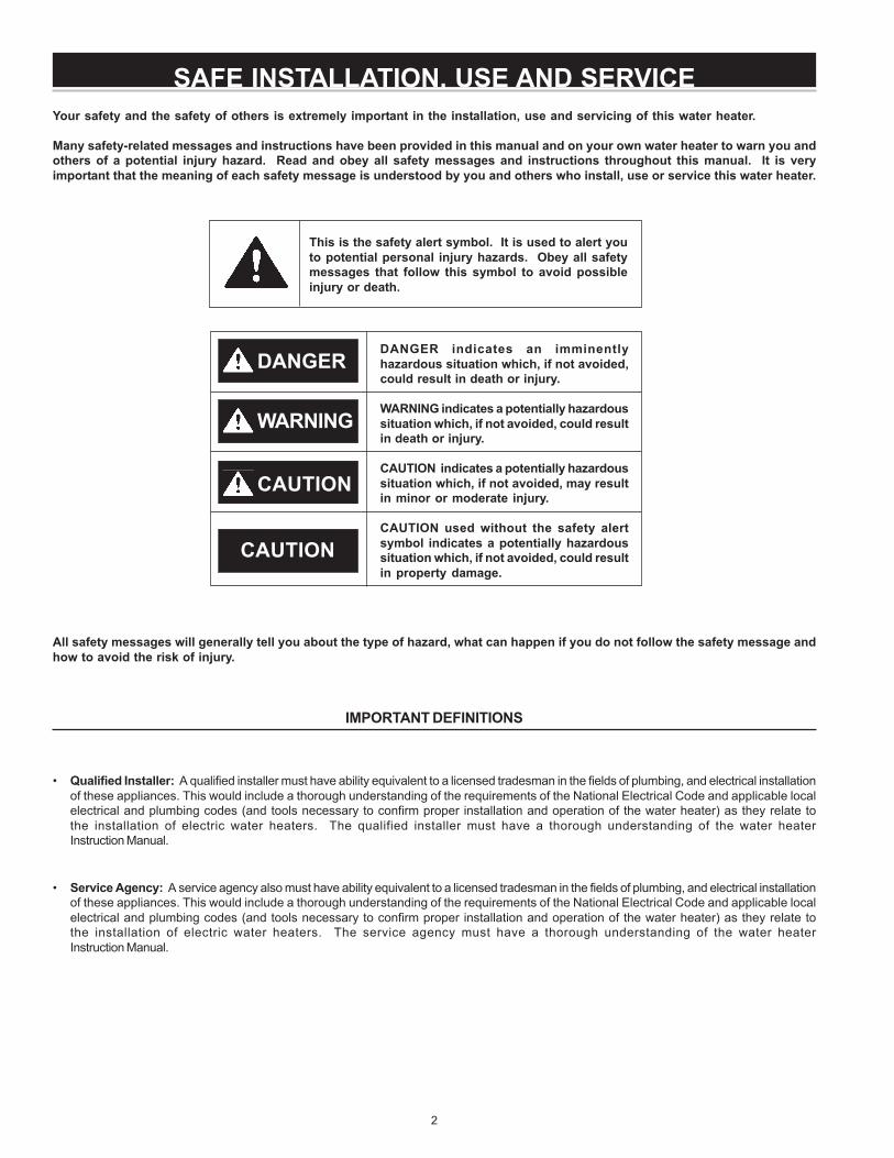
This is the safety alert symbol. It is used to alert youto potential personal injury hazards. Obey all safetymessages that follow this symbol to avoid possibleinjury or death.
All safety messages will generally tell you about the type of hazard, what can happen if you do not follow the safety message andhow to avoid the risk of injury.
IMPORTANT DEFINITIONS
• Qualified Installer: A qualified installer must have ability equivalent to a licensed tradesman in the fields of plumbing, and electrical installationof these appliances. This would include a thorough understanding of the requirements of the National Electrical Code and applicable localelectrical and plumbing codes (and tools necessary to confirm proper installation and operation of the water heater) as they relate tothe installation of electric water heaters. The qualified installer must have a thorough understanding of the water heaterInstruction Manual.
• Service Agency: A service agency also must have ability equivalent to a licensed tradesman in the fields of plumbing, and electrical installationof these appliances. This would include a thorough understanding of the requirements of the National Electrical Code and applicable localelectrical and plumbing codes (and tools necessary to confirm proper installation and operation of the water heater) as they relate tothe installation of electric water heaters. The service agency must have a thorough understanding of the water heaterInstruction Manual.
DANGER
WARNING
CAUTION
DANGER indicates an imminentlyhazardous situation which, if not avoided,could result in death or injury.
WARNING indicates a potentially hazardoussituation which, if not avoided, could resultin death or injury.
CAUTION indicates a potentially hazardoussituation which, if not avoided, may resultin minor or moderate injury.
CAUTION used without the safety alertsymbol indicates a potentially hazardoussituation which, if not avoided, could resultin property damage.
CAUTION
3
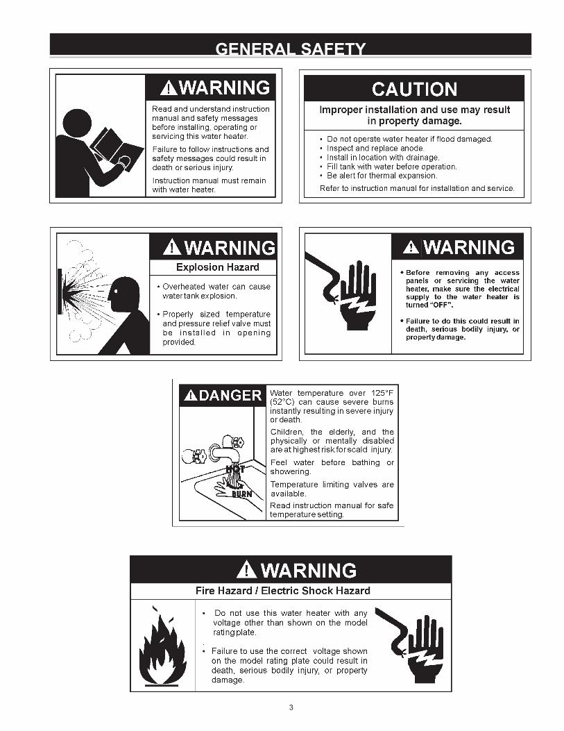
GENERAL SAFETY

4
Thank You for purchasing this water heater. Properly installed andmaintained, it should give you years of trouble free service.
Abbreviations Found In This Instruction Manual:• ANSI - American National Standards Institute
• ASME - American Society of Mechanical Engineers• GAMA - Gas Appliance Manufacturers Association• NEC - National Electrical Code
• NFPA - National Fire Protection Association• UL - Underwriters Laboratories Inc.
PREPARING FOR THE INSTALLATION
1. Read the “General Safety” section of this manual first and then theentire manual carefully. If you don’t follow the safety rules, thewater heater will not operate properly. It could cause DEATH,SERIOUS BODILY INJURY AND/OR PROPERTY DAMAGE.
This manual contains instructions for the installation, operation, andmaintenance of the electric water heater. It also contains warningsthroughout the manual that you must read and be aware of. Allwarnings and all instructions are essential to the proper operation ofthe water heater and your safety. Since we cannot put everythingon the first few pages, READ THE ENTIRE MANUAL BEFOREATTEMPTING TO INSTALL OR OPERATE THE WATER HEATER.
2. The installation must conform with these instructions and the localcode authority having jurisdiction and the requirements of the powercompany. In the absence of code requirements follow NFPA-70(latest edition). The National Electric Code which may be orderedfrom: National Fire Protection Association, 1 Batterymarch Park,Quincy, MA 02269.
3. If after reading this manual you have any questions or do notunderstand any portion of the instructions, call the local utility or themanufacturer whose name appears on the rating plate.
4. Carefully plan the place where you are going to put the water heater.INSTALLATION OR SERVICE OF THIS WATER HEATER REQUIRESABILITY EQUIVALENT TO THAT OF A LICENSED TRADESMAN INTHE FIELD INVOLVED. PLUMBING AND ELECTRICAL WORK AREREQUIRED.
Examine the location to ensure the water heater complies with the“Facts to Consider About the Location” section in this manual.
5. For California installation this water heater must be braced, anchored,or strapped to avoid falling or moving during an earthquake. Seeinstructions for correct installation procedures. Instructions may beobtained from California Office of the State Architect, 400 P Street,Sacramento, CA 95814.
6. Massachusetts Code requires this water heater to be installed inaccordance with Massachusetts 248-CMR 2.00: State Plumbing Codeand 248-CMR 5.00.
INTRODUCTION
5
SAFE INSTALLATION, USE AND SERVICE ................................................................................................................................... 2
GENERAL SAFETY ........................................................................................................................................................................... 3
INTRODUCTION .............................................................................................................................................................................. 4
Preparing for the New Installation .......................................................................................................................................... 4
TABLE OF CONTENTS .................................................................................................................................................................... 5
TYPICAL INSTALLATION .................................................................................................................................................................. 6
MIXING VALVE USAGE ..................................................................................................................................................................... 7
LOCATING THE NEW WATER HEATER ......................................................................................................................................... 8
Facts to Consider About Location ........................................................................................................................................... 8
Insulation Blankets ................................................................................................................................................................... 8
INSTALLING THE NEW WATER HEATER ...................................................................................................................................... 8
Water Piping .......................................................................................................................................................................... 8-9
Temperature-Pressure Relief Valve ................................................................................................................................. 9-10
Filling the Water Heater ......................................................................................................................................................... 10
T & P Valve and Pipe Insulation (Selected Models) ........................................................................................................ 10
WIRING DIAGRAMS ....................................................................................................................................................................... 11
WIRING ........................................................................................................................................................................................... 12
TEMPERATURE REGULATION ..................................................................................................................................................... 13
Temperature Adjustment ....................................................................................................................................................... 13
FOR YOUR INFORMATION ............................................................................................................................................................ 14
Thermal Expansion ................................................................................................................................................................ 14
Strange Sounds .................................................................................................................................................................. 14
Operational Conditions .......................................................................................................................................................... 14
Smelly Water ........................................................................................................................................................................ 14
“Air” in Hot Water Faucets .................................................................................................................................................. 14
High Water Temperature Shut Off System ........................................................................................................................ 14
PERIODIC MAINTENANCE ........................................................................................................................................................... 15
Anode Rod Inspection ............................................................................................................................................................ 15
Temperature-Pressure Relief Valve Operation ................................................................................................................... 15
Draining ................................................................................................................................................................................... 15
Thermostat Removal/Replacement ............................................................................................................................... 15-16
Element Cleaning/Replacement .................................................................................................................................... 16-18
Drain Valve Washer Replacement ........................................................................................................................................ 18
Service ..................................................................................................................................................................................... 18
LEAKAGE CHECKPOINTS ............................................................................................................................................................ 19
TROUBLESHOOTING GUIDELINES ............................................................................................................................................ 20
REPAIR PARTS LIST ................................................................................................................................................................ 21-23
WARRANTY ............................................................................................................................................................................... 24-25
NOTES ............................................................................................................................................................................................ 26
TABLE OF CONTENTS
6
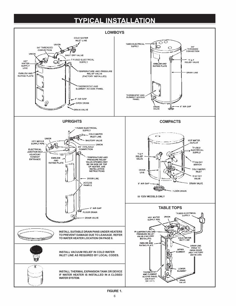
TYPICAL INSTALLATION
FIGURE 1.
UPRIGHTS COMPACTS
TABLE TOPS
INSTALL VACUUM RELIEF IN COLD WATERINLET LINE AS REQUIRED BY LOCAL CODES.
INSTALL SUITABLE DRAIN PANS UNDER HEATERSTO PREVENT DAMAGE DUE TO LEAKAGE. REFERTO WATER HEATER LOCATION ON PAGE 8.
INSTALL THERMAL EXPANSION TANK OR DEVICEIF WATER HEATER IS INSTALLED IN A CLOSEDWATER SYSTEM.
LOWBOYS
7
MIXING VALVE USAGE
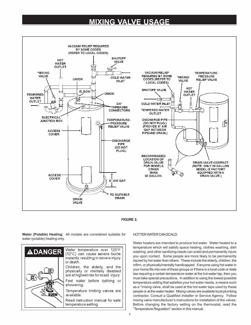
FIGURE 2.
Water (Potable) Heating: All models are considered suitable forwater (potable) heating only.
HOTTER WATER CAN SCALD:
Water heaters are intended to produce hot water. Water heated to atemperature which will satisfy space heating, clothes washing, dishwashing, and other sanitizing needs can scald and permanently injureyou upon contact. Some people are more likely to be permanentlyinjured by hot water than others. These include the elderly, children, theinfirm, or physically/mentally handicapped. If anyone using hot water inyour home fits into one of these groups or if there is a local code or statelaw requiring a certain temperature water at the hot water tap, then youmust take special precautions. In addition to using the lowest possibletemperature setting that satisfies your hot water needs, a means suchas a *mixing valve, shall be used at the hot water taps used by thesepeople or at the water heater. Mixing valves are available local plumbingcontractor. Consult a Qualified Installer or Service Agency. Followmixing valve manufacturer’s instructions for installation of the valves.Before changing the factory setting on the thermostat, read the“Temperature Regulation” section in this manual.
8
FACTS TO CONSIDER ABOUT THE LOCATION
Carefully choose an indoor location for the new water heater, becausethe placement is a very important consideration for the safety of theoccupants in the building and for the most economical use of theappliance.
Whether replacing an old water heater or putting the water heater in anew location, the following critical points must be observed:
1. Select a location indoors as close as practical or centralized to thewater piping system as possible. The water heater should belocated in an area not subject to freezing temperatures.
2. Selected location must provide adequate clearances (4”) for servicingparts such as the thermostats, drain valve and relief valve. Adequateclearance for servicing this appliance should be considered beforeinstallation, such as changing the anodes, etc.
Installation of the water heater must be accomplished in such a mannerthat if the tank or any connections should leak, the flow will not cause
LOCATING THE NEW WATER HEATERdamage to the structure. For this reason, it is not advisable to install thewater heater in an attic or upper floor. When such locations cannot beavoided, a suitable drain pan should be installed under the water heater.Drain pans are available from your local plumbing contractor. Such adrain pan must have a minimum length and width of at least 2 inches(51 mm) greater that the water heater dimensions and must be piped toan adequate drain.
Also, the water heater must be located and/or protected so it is notsubject to physical damage by a moving vehicle.
INSULATION BLANKETS
Insulation blankets are available to the general public for external useon electric water heaters but are not necessary with this product. Thepurpose of an insulation blanket is to reduce the standby heat lossencountered with storage tank heaters. Your water heater meets orexceeds the National Appliance Energy Conversation Act standardswith respect to insulation and standby loss requirements, making aninsulation blanket unnecessary.
Should you choose to apply an insulation blanket to this heater, youshould follow these instructions below. Failure to follow theseinstructions can result in fire, serious personal injury, or death.
• Do not cover the temperature and pressure relief (T & P) valve withan insulation blanket.
• Do not cover the instruction manual. Keep it on the side of thewater heater or nearby for future reference.
• Do obtain new warning and instruction labels for placement on theblanket directly over the existing labels.
INSTALLING THE NEW WATER HEATERWATER PIPING
HOTTER WATER CAN SCALD:Water heaters are intended to produce hot water. Water heated to atemperature which will satisfy space heating, clothes washing, dishwashing, cleaning and other sanitizing needs can scald and permanentlyinjure you upon contact. Some people are more likely to be permanentlyinjured by hot water than others. These include the elderly, children,the infirm, or physically/mentally handicapped. If anyone using hotwater in your home fits into one of these groups or if there is a localcode or state law requiring a certain temperature water at the hotwater tap, then you must take special precautions. In addition to usingthe lowest possible temperature setting that satisfies your hot waterneeds, a means such as a *mixing valve, shall be used at the hot water
taps used by these people or at the water heater. Valves for reducingpoint of use temperature by mixing cold and hot water are also available.
Consult a Qualified Installer or Service Agency. Follow manufacturer’sinstructions for installation of the valves. Before changing the factorysetting on the thermostat, read the “Temperature Regulation” section inthis manual.
This water heater shall not be connected to any heating systems orcomponent(s) used with a non-potable water heating appliance.
Toxic chemicals, such as those used for boiler treatment shall not beintroduced into this system.
Water supply systems may, because of such events as high linepressure, frequent cut-offs, the effects of water hammer amongothers, have installed devices such as pressure reducing valves, checkvalves, back flow preventers, etc. to control these types of problems.When these devices are not equipped with an internal by-pass, and noother measures are taken, the devices cause the water system to beclosed. As water is heated, it expands (thermal expansion) and closedsystems do not allow for the expansion of heated water.
9
The water within the water heater tank expands as it is heated andincreases the pressure of the water system. If the relieving point ofthe water heater’s temperature-pressure relief valve is reached, thevalve will relieve the excess pressure. The temperature-pressurerelief valve is not intended for the constant relief of thermalexpansion. This is an unacceptable condition and must be corrected.It is recommended that any devices installed which could create aclosed system have a by-pass and/or the system have an expansiontank or device to relieve the pressure built by thermal expansion in thewater system. Expansion tanks are available for ordering through alocal plumbing contractor. Contact the local water supplier and/or aservice agency for assistance in controlling these situations.
NOTE: To protect against untimely corrosion of hot and coldwater fittings, it is strongly recommended that di-electricunions or couplings be installed on this water heater whenconnected to copper pipe.
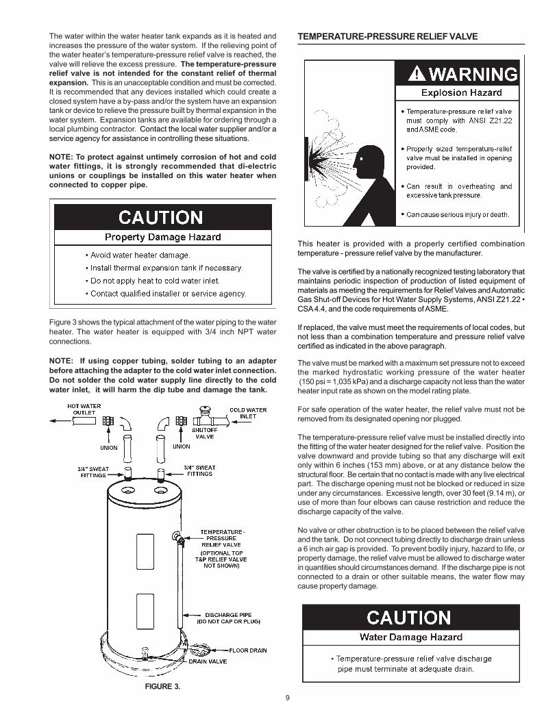
Figure 3 shows the typical attachment of the water piping to the waterheater. The water heater is equipped with 3/4 inch NPT waterconnections.
NOTE: If using copper tubing, solder tubing to an adapterbefore attaching the adapter to the cold water inlet connection.Do not solder the cold water supply line directly to the coldwater inlet, it will harm the dip tube and damage the tank.
FIGURE 3.
TEMPERATURE-PRESSURE RELIEF VALVE
This heater is provided with a properly certified combinationtemperature - pressure relief valve by the manufacturer.
The valve is certified by a nationally recognized testing laboratory thatmaintains periodic inspection of production of listed equipment ofmaterials as meeting the requirements for Relief Valves and AutomaticGas Shut-off Devices for Hot Water Supply Systems, ANSI Z21.22 •CSA 4.4, and the code requirements of ASME.
If replaced, the valve must meet the requirements of local codes, butnot less than a combination temperature and pressure relief valvecertified as indicated in the above paragraph.
The valve must be marked with a maximum set pressure not to exceedthe marked hydrostatic working pressure of the water heater (150 psi = 1,035 kPa) and a discharge capacity not less than the waterheater input rate as shown on the model rating plate.
For safe operation of the water heater, the relief valve must not beremoved from its designated opening nor plugged.
The temperature-pressure relief valve must be installed directly intothe fitting of the water heater designed for the relief valve. Position thevalve downward and provide tubing so that any discharge will exitonly within 6 inches (153 mm) above, or at any distance below thestructural floor. Be certain that no contact is made with any live electricalpart. The discharge opening must not be blocked or reduced in sizeunder any circumstances. Excessive length, over 30 feet (9.14 m), oruse of more than four elbows can cause restriction and reduce thedischarge capacity of the valve.
No valve or other obstruction is to be placed between the relief valveand the tank. Do not connect tubing directly to discharge drain unlessa 6 inch air gap is provided. To prevent bodily injury, hazard to life, orproperty damage, the relief valve must be allowed to discharge waterin quantities should circumstances demand. If the discharge pipe is notconnected to a drain or other suitable means, the water flow maycause property damage.
10
The Discharge Pipe:
• Shall not be smaller in size than the outlet pipe size of the valve, orhave any reducing couplings or other restrictions.
• Shall not be plugged or blocked.
• Shall be of material listed for hot water distribution.
• Shall be installed so as to allow complete drainage of both thetemperature-pressure relief valve, and the discharge pipe.
• Shall terminate at an adequate drain.
• Shall not have any valve between the relief valve and tank.
The temperature-pressure relief valve must be manually operated atleast once a year. Caution should be taken to ensure that (1) no one isin front of or around the outlet of the temperature-pressure relief valvedischarge line, and (2) the water manually discharged will not causeany bodily injury or property damage because the water may beextremely hot.
FIGURE 4.
If after manually operating the valve, it fails to completely reset andcontinues to release water, immediately close the cold water inlet tothe water heater, follow the draining instructions, and replace thetemperature-pressure relief valve with a new one.
FILLING THE WATER HEATER
Never use this water heater unless it is completely full of water. Toprevent damage to the tank, the tank must be filled with water. Watermust flow from the hot water faucet before turning “ON” electricalsupply to the water heater.
To fill the water heater with water:
1. Close the water heater drain valve by turning the handle to the right(clockwise). The drain valve is on the lower front of the waterheater.
2. Open the cold water supply valve to the water heater.NOTE: The cold water supply valve must be left open whenthe water heater is in use.
3. To insure complete filling of the tank, allow air to exit by opening thenearest hot water faucet. Allow water to run until a constant flowis obtained. This will let air out of the water heater and the piping.
4. Check all water piping and connections for leaks. Repair as needed.
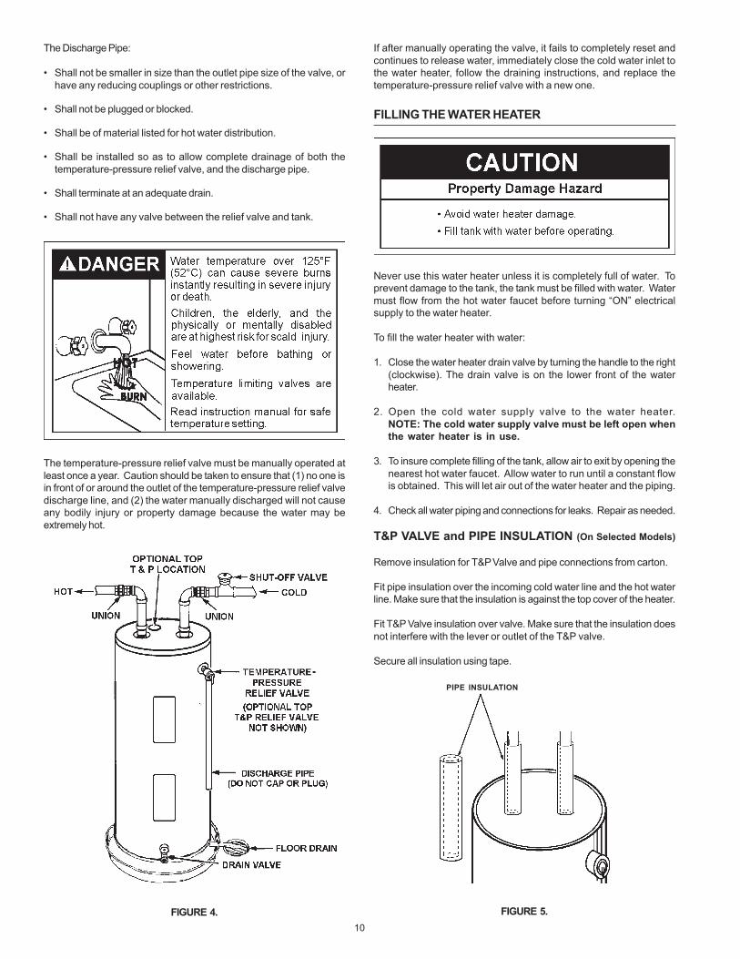
T&P VALVE and PIPE INSULATION (On Selected Models)
Remove insulation for T&P Valve and pipe connections from carton.
Fit pipe insulation over the incoming cold water line and the hot waterline. Make sure that the insulation is against the top cover of the heater.
Fit T&P Valve insulation over valve. Make sure that the insulation doesnot interfere with the lever or outlet of the T&P valve.
Secure all insulation using tape.
FIGURE 5.
PIPE INSULATION
11
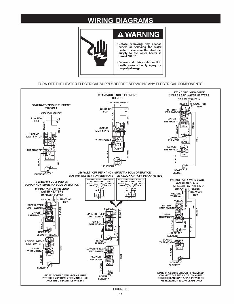
WIRING DIAGRAMS
TURN OFF THE HEATER ELECTRICAL SUPPLY BEFORE SERVICING ANY ELECTRICAL COMPONENTS.
FIGURE 6.
12
WIRING
Never use water heater unless it is completely full of water. To preventdamage to the tank and heating element, the tank must be filled withwater. Water must flow from the hot water faucet before turning onpower.
You must provide all wiring of the proper size outside of the waterheater. You must obey local codes and electric company requirementswhen you install this wiring.
If you are not familiar with electric codes and practices, or if you haveany doubt, even the slightest doubt, in your ability to connect the wiringto this water heater, obtain the service of a competent electrician.Contact a local electrical contractor and/or the local electric utility.
WATER HEATERS EQUIPPED FOR ONE VOLTAGE ONLY: This waterheater is equipped for one type voltage only. Check the rating platenear the bottom access panel for the correct voltage. DO NOT use thiswater heater with any voltage other than the one shown on the modelrating plate. Failure to use the correct voltage can cause problemswhich can result in DEATH, SERIOUS BODILY INJURY, OR PROPERTYDAMAGE. If you have any questions or doubts consult your electriccompany.
If wiring from your fuse box or circuit breaker box was aluminum foryour old water heater, replace it with copper wire. If you wish to reusethe existing aluminum wire, have the connection at the water heatermade by a competent electrician. Contact a local electrical contractorand/or the local electric utility.
1. Provide a way to easily shut off the electric power when workingon the water heater. This could be with a circuit breaker or fuseblock in the entrance box or a separate disconnect switch.
2. Install and connect a circuit directly from the main fuse or circuitbreaker box. This circuit must be the right size and have its ownfuse or circuit breaker.
3. If metal conduit is used for the grounding conductor:
A. The grounding electrode conductor shall be of copper, aluminum,or copperclad aluminum. The material shall be of one continuouslength without a splice or joint.
B. Rigid metal conduit, intermediate metal conduit, or electrical,metallic tubing may be used for the grounding means if conduit ortubing is terminated in fittings approved for grounding.
C. Flexible metal conduit or flexible metallic tubing shall be permittedfor grounding if all the following conditions are met:
• The length in any ground return path does not exceed 6 feet.
• The circuit conductors contained therein are protected byovercurrent devices rated at 20 amperes or less.
• The conduit or tubing is terminated in fittings approved forgrounding.
For complete grounding details and all allowable exceptions, refer tothe current edition of the National Electrical Code NFPA 70.
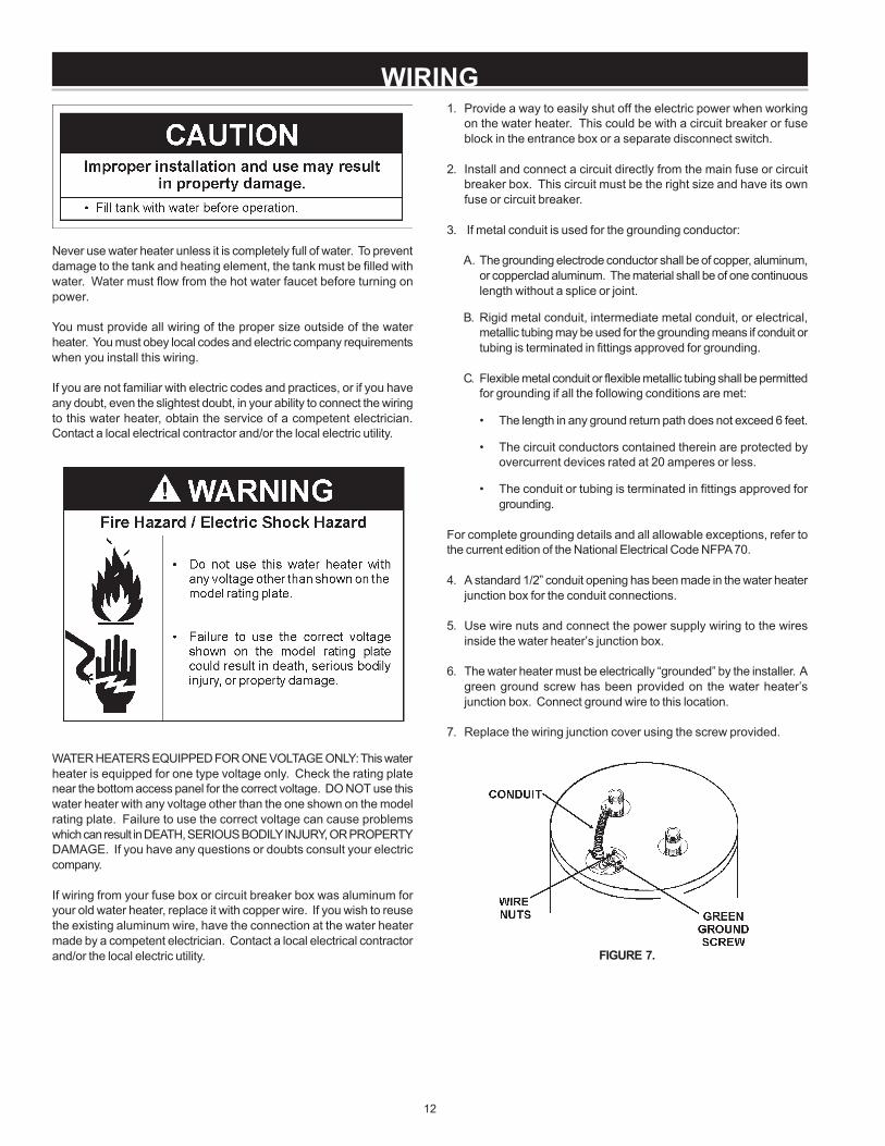
4. A standard 1/2” conduit opening has been made in the water heaterjunction box for the conduit connections.
5. Use wire nuts and connect the power supply wiring to the wiresinside the water heater’s junction box.
6. The water heater must be electrically “grounded” by the installer. Agreen ground screw has been provided on the water heater’sjunction box. Connect ground wire to this location.
7. Replace the wiring junction cover using the screw provided.
FIGURE 7.
13
TEMPERATURE ADJUSTMENT
To change the temperature setting:
NOTE: It is not necessary to adjust the upper thermostat. However, if itis adjusted above the factory set point (120°F (49°C)/HOT) it isrecommended that it not be set higher than the lower thermostat setting.
1. Turn off the heater electrical supply. Do not attempt to adjustthermostat with power on.
2. Remove the thermostat access panels and covers from thethermostats. Do not remove the plastic personnel protectors coveringthe thermostats.
3. Using a flat tip screwdriver, rotate the adjustment knob to the desiredtemperature setting.
4. Replace the covers and access panels and turn on heater electricalsupply.
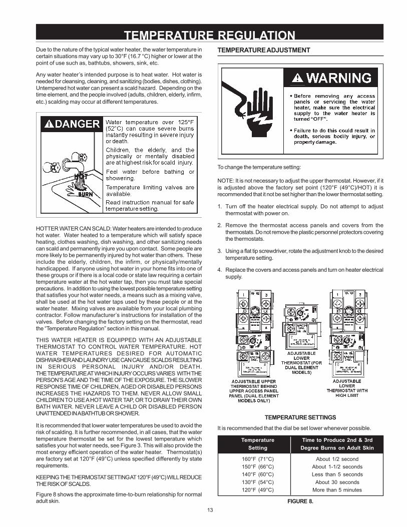
TEMPERATURE SETTINGS
It is recommended that the dial be set lower whenever possible.
Temperature Time to Produce 2nd & 3rdSetting Degree Burns on Adult Skin
160°F (71°C) About 1/2 second150°F (66°C) About 1-1/2 seconds140°F (60°C) Less than 5 seconds130°F (54°C) About 30 seconds120°F (49°C) More than 5 minutes
FIGURE 8.
Due to the nature of the typical water heater, the water temperature incertain situations may vary up to 30°F (16.7 °C) higher or lower at thepoint of use such as, bathtubs, showers, sink, etc.
Any water heater’s intended purpose is to heat water. Hot water isneeded for cleansing, cleaning, and sanitizing (bodies, dishes, clothing).Untempered hot water can present a scald hazard. Depending on thetime element, and the people involved (adults, children, elderly, infirm,etc.) scalding may occur at different temperatures.
HOTTER WATER CAN SCALD: Water heaters are intended to producehot water. Water heated to a temperature which will satisfy spaceheating, clothes washing, dish washing, and other sanitizing needscan scald and permanently injure you upon contact. Some people aremore likely to be permanently injured by hot water than others. Theseinclude the elderly, children, the infirm, or physically/mentallyhandicapped. If anyone using hot water in your home fits into one ofthese groups or if there is a local code or state law requiring a certaintemperature water at the hot water tap, then you must take specialprecautions. In addition to using the lowest possible temperature settingthat satisfies your hot water needs, a means such as a mixing valve,shall be used at the hot water taps used by these people or at thewater heater. Mixing valves are available from your local plumbingcontractor. Follow manufacturer’s instructions for installation of thevalves. Before changing the factory setting on the thermostat, readthe “Temperature Regulation” section in this manual.
THIS WATER HEATER IS EQUIPPED WITH AN ADJUSTABLETHERMOSTAT TO CONTROL WATER TEMPERATURE. HOTWATER TEMPERATURES DESIRED FOR AUTOMATICDISHWASHER AND LAUNDRY USE CAN CAUSE SCALDS RESULTINGIN SERIOUS PERSONAL INJURY AND/OR DEATH.THE TEMPERATURE AT WHICH INJURY OCCURS VARIES WITH THEPERSON’S AGE AND THE TIME OF THE EXPOSURE. THE SLOWERRESPONSE TIME OF CHILDREN, AGED OR DISABLED PERSONSINCREASES THE HAZARDS TO THEM. NEVER ALLOW SMALLCHILDREN TO USE A HOT WATER TAP, OR TO DRAW THEIR OWNBATH WATER. NEVER LEAVE A CHILD OR DISABLED PERSONUNATTENDED IN A BATHTUB OR SHOWER.
It is recommended that lower water temperatures be used to avoid therisk of scalding. It is further recommended, in all cases, that the watertemperature thermostat be set for the lowest temperature whichsatisfies your hot water needs, see Figure 3. This will also provide themost energy efficient operation of the water heater. Thermostat(s)are factory set at 120°F (49°C) unless specified differently by staterequirements.
KEEPING THE THERMOSTAT SETTING AT 120°F (49°C) WILL REDUCETHE RISK OF SCALDS.
Figure 8 shows the approximate time-to-burn relationship for normaladult skin.
TEMPERATURE REGULATION
14
THERMAL EXPANSION
Water supply systems may, because of such events as high linepressure, frequent cut-offs, the effects of water hammer amongothers, have installed devices such as pressure reducing valves, checkvalves, back flow preventers, etc. to control these types of problems.When these devices are not equipped with an internal by-pass, and noother measures are taken, the devices cause the water system to beclosed. As water is heated, it expands (thermal expansion) and closedsystems do not allow for the expansion of heated water.
The water within the water heater tank expands as it is heated andincreases the pressure of the water system. If the relieving point ofthe water heater’s temperature-pressure relief valve is reached, thevalve will relieve the excess pressure. The temperature-pressurerelief valve is not intended for the constant relief of thermalexpansion. This is an unacceptable condition and must be corrected.It is recommended that any devices installed which could create aclosed system have a by-pass and/or the system have an expansiontank or device to relieve the pressure built by thermal expansion in thewater system. Expansion tanks are available for ordering through alocal plumbing contractor. Contact the local water heater supplier orservice agency for assistance in controlling these situations.
STRANGE SOUNDS
Possible noises due to expansion and contraction of some metal partsduring periods of heat-up and cool-down do not necessarily representharmful or dangerous conditions.
OPERATIONAL CONDITIONS
SMELLY WATER
In each water heater there is installed at least one anode rod (seeparts sections) for corrosion protection of the tank. Certain waterconditions will cause a reaction between this rod and the water. Themost common complaint associated with the anode rod is one of a“rotten egg smell” in the hot water. This odor is derived from hydrogensulfide gas dissolved in the water. The smell is the result of fourfactors which must all be present for the odor to develop:
A. A concentration of sulfate in the supply water.B. Little or no dissolved oxygen in the water.C. A sulfate reducing bacteria which has accumulated within the water
heater (this harmless bacteria is nontoxic to humans).D. An excess of active hydrogen in the tank. This is caused by the
corrosion protective action of the anode.
Smelly water may be eliminated or reduced in some water heatermodels by replacing the anode(s) with one of less active material, andthen chlorinating the water heater tank and all hot water lines. Contactthe local water heater supplier or service agency for further informationconcerning an Anode Replacement Kit and this chlorination treatment.If the smelly water persists after the anode replacement and chlorinationtreatment, we can only suggest that chlorination or aeration of thewater supply be considered to eliminate the water problem.
Do not remove the anode leaving the tank unprotected. Bydoing so, all warranty on the water heater tank is voided.
“AIR” IN HOT WATER FAUCETS
HYDROGEN GAS: Hydrogen gas can be produced in a hot watersystem that has not been used for a long period of time (generally twoweeks or more). Hydrogen gas is extremely flammable and explosive.To prevent the possibility of injury under these conditions, werecommend the hot water faucet, located farthest away, be openedfor several minutes before any electrical appliances which areconnected to the hot water system are used (such as a dishwasher orwashing machine). If hydrogen gas is present, there will probably bean unusual sound similar to air escaping through the pipe as the hotwater faucet is opened. There must be no smoking or open flame nearthe faucet at the time it is open.
HIGH WATER TEMPERATURE SHUT OFF SYSTEM
A non-adjustable high temperature limit control operates before steamtemperatures are reached. The high limit is in the same area as theupper thermostat and must be reset manually when it operates.BECAUSE THE HIGH LIMIT OPERATES ONLY WHENABNORMALLY HIGH WATER TEMPERATURES ARE PRESENT, ITIS IMPORTANT THAT A QUALIFIED SERVICE AGENT BE CONTACTEDTO DETERMINE THE REASON FOR OPERATION BEFORE RESETTING.
• Turn off the heater electrical supply. Do not attempt to reset thermostatwith power on.
• Remove the two screws securing the outer door and remove door.
• Remove the insulation block and pad to expose the reset buttonopening.
• Reset the high limit by pushing in the red button marked “RESET”.
• Replace the insulation block and pad so that it completely coversthe thermostat and element.
• Replace the outer door.
• Turn “ON” electric power to the water heater.
FOR YFOR YFOR YFOR YFOR YOUR INFORMAOUR INFORMAOUR INFORMAOUR INFORMAOUR INFORMATIONTIONTIONTIONTION
15
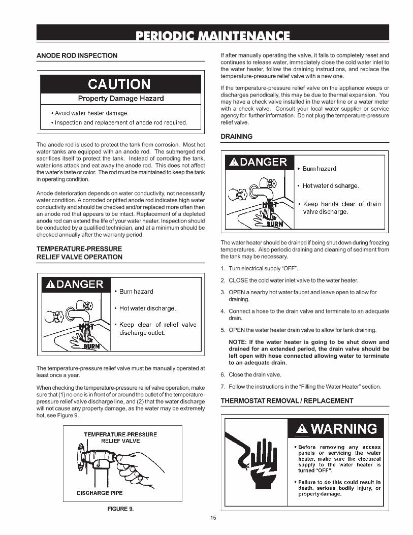
If after manually operating the valve, it fails to completely reset andcontinues to release water, immediately close the cold water inlet tothe water heater, follow the draining instructions, and replace thetemperature-pressure relief valve with a new one.
If the temperature-pressure relief valve on the appliance weeps ordischarges periodically, this may be due to thermal expansion. Youmay have a check valve installed in the water line or a water meterwith a check valve. Consult your local water supplier or serviceagency for further information. Do not plug the temperature-pressurerelief valve.
DRAINING
The water heater should be drained if being shut down during freezingtemperatures. Also periodic draining and cleaning of sediment fromthe tank may be necessary.
1. Turn electrical supply “OFF”.
2. CLOSE the cold water inlet valve to the water heater.
3. OPEN a nearby hot water faucet and leave open to allow fordraining.
4. Connect a hose to the drain valve and terminate to an adequatedrain.
5. OPEN the water heater drain valve to allow for tank draining.
NOTE: If the water heater is going to be shut down anddrained for an extended period, the drain valve should beleft open with hose connected allowing water to terminateto an adequate drain.
6. Close the drain valve.
7. Follow the instructions in the “Filling the Water Heater” section.
THERMOSTAT REMOVAL / REPLACEMENT
ANODE ROD INSPECTION
The anode rod is used to protect the tank from corrosion. Most hotwater tanks are equipped with an anode rod. The submerged rodsacrifices itself to protect the tank. Instead of corroding the tank,water ions attack and eat away the anode rod. This does not affectthe water’s taste or color. The rod must be maintained to keep the tankin operating condition.
Anode deterioration depends on water conductivity, not necessarilywater condition. A corroded or pitted anode rod indicates high waterconductivity and should be checked and/or replaced more often thenan anode rod that appears to be intact. Replacement of a depletedanode rod can extend the life of your water heater. Inspection shouldbe conducted by a qualified technician, and at a minimum should bechecked annually after the warranty period.
TEMPERATURE-PRESSURERELIEF VALVE OPERATION
The temperature-pressure relief valve must be manually operated atleast once a year.
When checking the temperature-pressure relief valve operation, makesure that (1) no one is in front of or around the outlet of the temperature-pressure relief valve discharge line, and (2) that the water dischargewill not cause any property damage, as the water may be extremelyhot, see Figure 9.
FIGURE 9.
PERIODIC MAINTENANCEPERIODIC MAINTENANCEPERIODIC MAINTENANCEPERIODIC MAINTENANCEPERIODIC MAINTENANCE
16
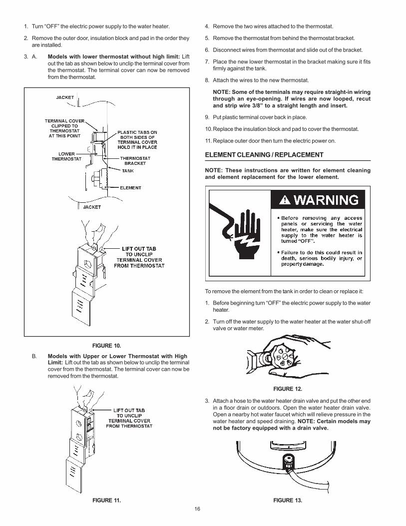
1. Turn “OFF” the electric power supply to the water heater.
2. Remove the outer door, insulation block and pad in the order theyare installed.
3. A. Models with lower thermostat without high limit: Liftout the tab as shown below to unclip the terminal cover fromthe thermostat. The terminal cover can now be removedfrom the thermostat.
FIGURE 10.
B. Models with Upper or Lower Thermostat with HighLimit: Lift out the tab as shown below to unclip the terminalcover from the thermostat. The terminal cover can now beremoved from the thermostat.
FIGURE 11.
4. Remove the two wires attached to the thermostat.
5. Remove the thermostat from behind the thermostat bracket.
6. Disconnect wires from thermostat and slide out of the bracket.
7. Place the new lower thermostat in the bracket making sure it fitsfirmly against the tank.
8. Attach the wires to the new thermostat.
NOTE: Some of the terminals may require straight-in wiringthrough an eye-opening. If wires are now looped, recutand strip wire 3/8” to a straight length and insert.
9. Put plastic terminal cover back in place.
10.Replace the insulation block and pad to cover the thermostat.
11. Replace outer door then turn the electric power on.
ELEMENT CLEANING / REPLACEMENT
NOTE: These instructions are written for element cleaningand element replacement for the lower element.
To remove the element from the tank in order to clean or replace it:
1. Before beginning turn “OFF” the electric power supply to the waterheater.
2. Turn off the water supply to the water heater at the water shut-offvalve or water meter.
FIGURE 12.
3. Attach a hose to the water heater drain valve and put the other endin a floor drain or outdoors. Open the water heater drain valve.Open a nearby hot water faucet which will relieve pressure in thewater heater and speed draining. NOTE: Certain models maynot be factory equipped with a drain valve.
FIGURE 13.

17
The water passing out of the drain valve may be extremely hot. Toavoid being scald, make sure all connections are tight and that thewater flow is directed away from any person.
4. Remove the two screws securing the outer door, and remove door.
FIGURE 14.
5. Remove the insulation block and pad.
FIGURE 15.
6. A. Models with lower thermostat without high limit: Liftout the tab as shown below to unclip the terminal cover fromthe thermostat. The terminal cover can now be removedfrom the thermostat.
FIGURE 16.
B. Models with Upper or Lower Thermostat with HighLimit: Lift out the tab as shown below to unclip the terminalcover from the thermostat. The terminal cover can now beremoved from the thermostat.
FIGURE 17.
7. Disconnect the two wires on the element and unscrew the oldelement from the tank.
FIGURE 18.
8. Clean the area around the element opening. Remove any sedimentfrom or around the element opening and inside the tank.
9. If you are cleaning the element you have removed, do so by scrapingor soaking in vinegar or a deliming solution.
NOTE: Replacement elements must (1) be the same voltageand (2) no greater wattage than listed on the model ratingplate affixed to the water heater.
10.A new gasket should be used in all cases to prevent a possiblewater leak. Place the new element gasket on the threaded side ofthe cleaned or new element and screw into tank, securing tightlyusing an element wrench.
FIGURE 19.

18
11. Close the water heater drain valve by turning the handle to the right(clockwise). The drain valve is on the lower front of the waterheater.
12.Open the cold water supply valve to the water heater.
NOTE: The cold water supply valve must be left open whenthe water heater is in use.
13.To insure complete filling of the tank, allow air to exit by opening thenearest hot water faucet. Allow water to run until a constant flowis obtained. This will let air out of the water heater and the piping.
Never use this water heater unless it is completely full of water. Toprevent damage to the tank and heating element, the tank must be filledwith water. Water must flow from the hot water faucet before turning“ON” power.
14.Check element for water leaks. If leakage occurs, tighten elementor repeat Steps 2 and 3, remove element and reposition gasket.Then repeat Steps 10 through 14.
15.Reconnect the two wires to the element and then check to makesure the thermostat remains firmly against the surface of the tank.
FIGURE 20.
16.Replace terminal cover on thermostat making sure the locking tabson the terminal cover are in place.
17.Replace the insulation block and pad so that it covers the thermostatand element, see Figure 21.
18.Replace outer door.
19.Turn “ON” electric power to water heater.
FIGURE 21.
DRAIN VALVE WASHER REPLACEMENT
(See Figure 22)
1. Follow “Draining” instructions.
2. Turning counter clockwise ( ), remove the hex cap below thescrew handle.
3. Remove the washer and put the new one in place.
4. Screw the handle and cap assembly back into the drain valve andretighten using a wrench. DO NOT OVER TIGHTEN.
5. Follow instructions in the “Filling The Water Heater” section.
6. Check for leaks.
FIGURE 22.
SERVICE
If a condition persists or you are uncertain about the operation of thewater heater contact a service agency.
Use this guide to check a “Leaking” water heater. Many suspected“Leakers” are not leaking tanks. Often the source of the water can befound and corrected.
If you are not thoroughly familiar with your water heater and safetypractices, contact a qualified installer to check the water heater.
19
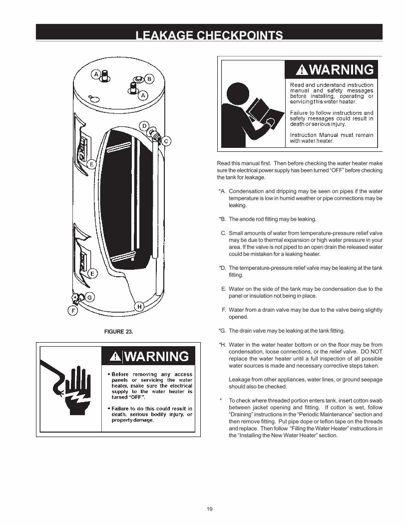
LEAKAGE CHECKPOINTS
Read this manual first. Then before checking the water heater makesure the electrical power supply has been turned “OFF” before checkingthe tank for leakage.
*A. Condensation and dripping may be seen on pipes if the watertemperature is low in humid weather or pipe connections may beleaking.
*B. The anode rod fitting may be leaking.
C. Small amounts of water from temperature-pressure relief valvemay be due to thermal expansion or high water pressure in yourarea. If the valve is not piped to an open drain the released watercould be mistaken for a leaking heater.
*D. The temperature-pressure relief valve may be leaking at the tankfitting.
E. Water on the side of the tank may be condensation due to thepanel or insulation not being in place.
F. Water from a drain valve may be due to the valve being slightlyopened.
*G. The drain valve may be leaking at the tank fitting.
*H. Water in the water heater bottom or on the floor may be fromcondensation, loose connections, or the relief valve. DO NOTreplace the water heater until a full inspection of all possiblewater sources is made and necessary corrective steps taken.
Leakage from other appliances, water lines, or ground seepageshould also be checked.
* To check where threaded portion enters tank, insert cotton swabbetween jacket opening and fitting. If cotton is wet, follow“Draining” instructions in the “Periodic Maintenance” section andthen remove fitting. Put pipe dope or teflon tape on the threadsand replace. Then follow “Filling the Water Heater” instructions inthe “Installing the New Water Heater” section.
FIGURE 23.
20
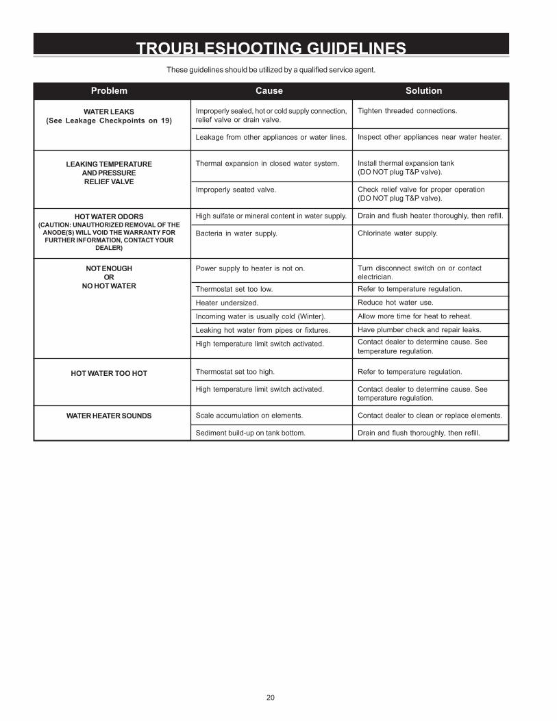
These guidelines should be utilized by a qualified service agent.
TROUBLESHOOTING GUIDELINES
Improperly sealed, hot or cold supply connection,relief valve or drain valve.
Leakage from other appliances or water lines.
Thermal expansion in closed water system.
Improperly seated valve.
High sulfate or mineral content in water supply.
Bacteria in water supply.
Power supply to heater is not on.
Thermostat set too low.
Heater undersized.
Incoming water is usually cold (Winter).
Leaking hot water from pipes or fixtures.
High temperature limit switch activated.
Thermostat set too high.
High temperature limit switch activated.
Scale accumulation on elements.
Sediment build-up on tank bottom.
Tighten threaded connections.
Inspect other appliances near water heater.
Install thermal expansion tank(DO NOT plug T&P valve).
Check relief valve for proper operation(DO NOT plug T&P valve).
Drain and flush heater thoroughly, then refill.
Chlorinate water supply.
Turn disconnect switch on or contactelectrician.Refer to temperature regulation.
Reduce hot water use.
Allow more time for heat to reheat.
Have plumber check and repair leaks.Contact dealer to determine cause. Seetemperature regulation.
Refer to temperature regulation.
Contact dealer to determine cause. Seetemperature regulation.
Contact dealer to clean or replace elements.
Drain and flush thoroughly, then refill.
Problem Cause Solution
WATER LEAKS(See Leakage Checkpoints on 19)
LEAKING TEMPERATUREAND PRESSURERELIEF VALVE
HOT WATER ODORS(CAUTION: UNAUTHORIZED REMOVAL OF THE
ANODE(S) WILL VOID THE WARRANTY FORFURTHER INFORMATION, CONTACT YOUR
DEALER)
NOT ENOUGHOR
NO HOT WATER
HOT WATER TOO HOT
WATER HEATER SOUNDS
21
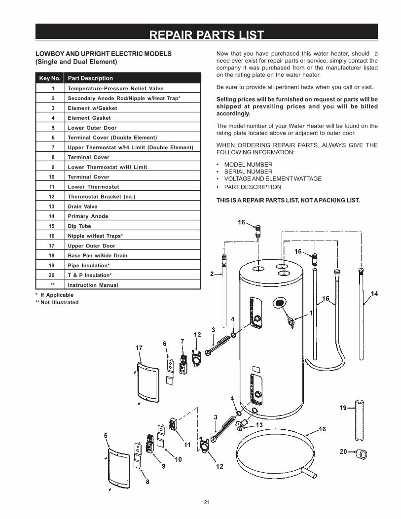
REPAIR PARTS LISTLOWBOY AND UPRIGHT ELECTRIC MODELS(Single and Dual Element)
Key No. Part Description1 Temperature-Pressure Relief Valve
2 Secondary Anode Rod/Nipple w/Heat Trap*
3 Element w/Gasket
4 Element Gasket
5 Lower Outer Door
6 Terminal Cover (Double Element)
7 Upper Thermostat w/Hi Limit (Double Element)
8 Terminal Cover
9 Lower Thermostat w/Hi Limit
10 Terminal Cover
11 Lower Thermostat
12 Thermostat Bracket (ea.)
13 Drain Valve
14 Primary Anode
15 Dip Tube
16 Nipple w/Heat Traps*
17 Upper Outer Door
18 Base Pan w/Side Drain
19 Pipe Insulation*
20 T & P Insulation*
** Instruction Manual
* If Applicable** Not Illustrated
Now that you have purchased this water heater, should aneed ever exist for repair parts or service, simply contact thecompany it was purchased from or the manufacturer listedon the rating plate on the water heater.
Be sure to provide all pertinent facts when you call or visit.
Selling prices will be furnished on request or parts will beshipped at prevailing prices and you will be billedaccordingly.
The model number of your Water Heater will be found on therating plate located above or adjacent to outer door.
WHEN ORDERING REPAIR PARTS, ALWAYS GIVE THEFOLLOWING INFORMATION:
• MODEL NUMBER• SERIAL NUMBER• VOLTAGE AND ELEMENT WATTAGE• PART DESCRIPTION
THIS IS A REPAIR PARTS LIST, NOT A PACKING LIST.

22
REPAIR PARTS LIST
WHEN ORDERING REPAIR PARTS, ALWAYS GIVE THEFOLLOWING INFORMATION:
• MODEL NUMBER
• SERIAL NUMBER
• VOLTAGE AND ELEMENT WATTAGE
• PART DESCRIPTION
THIS IS A REPAIR PARTS LIST, NOT A PACKING LIST.
Now that you have purchased this water heater, should aneed ever exist for repair parts or service, simply contact thecompany it was purchased from or the manufacturer listed onthe rating plate on the water heater.
Be sure to provide all pertinent facts when you call or visit.
Selling prices will be furnished on request or parts will beshipped at prevailing prices and you will be billed accordingly.
The model number of your Water Heater will be found on therating plate located above or adjacent to outer door.
Key No. Part Description1 Temperature-Pressure Relief Valve
2 Outlet Nipple Assembly
3 Inlet Nipple
4 Junction Box Cover
5 Upper and Lower Element
6 Element Gasket
7 Thermostat Bracket (ea.)
8 Lower Thermostat
9 Terminal Cover
10 Lower Thermostat w/Hi Limit
11 Terminal Cover
Key No. Part Description12 Lower Outer Door
13 Upper Outer Door
14 Upper Thermostat w/Hi/Limit
15 Anode Rod
16 Drain Valve (30 Gallon Model Only)
17 Base Pan w/Side Drain
18 Conduit Bracket
19 Pipe Insulation*
20 T & P Insulation*
** Instruction Manual
* If Applicable** Not Illustrated
COMPACT OR MANUFACTURED (MOBILE) HOME ELECTRIC MODELS

23
REPAIR PARTS LISTTABLE TOP ELECTRIC MODELS
Key No. Part Description1 Porcelain Top
2 Temperature and Pressure Relief Valve
3 Primary Anode Rod
4 Upper Thermostat w/Hi Limit
5 Dip Tube
6 Element w/Gasket
7 Element Gasket
8 Thermostat Bracket (ea.)
9 Terminal Cover
10 Outer Door (ea.)
11 Lower Thermostat w/Hi Limit
12 Terminal Cover
13 Lower Thermostat
14 Drain Access Door
15 Drain Valve
16 Toe Panel
** Instruction Manual
** Not Illustrated
Now that you have purchased this water heater, should aneed ever exist for repair parts or service, simply contact thecompany it was purchased from or the manufacturer listed onthe rating plate on the water heater.
Be sure to provide all pertinent facts when you call or visit.
Selling prices will be furnished on request or parts will beshipped at prevailing prices and you will be billed accordingly.
The model number of your Water Heater will be found on therating plate located above or adjacent to outer door.
WHEN ORDERING REPAIR PARTS, ALWAYS GIVE THEFOLLOWING INFORMATION:
• MODEL NUMBER
• SERIAL NUMBER
• VOLTAGE AND ELEMENT WATTAGE
• PART DESCRIPTION
THIS IS A REPAIR PARTS LIST, NOT A PACKING LIST.
24
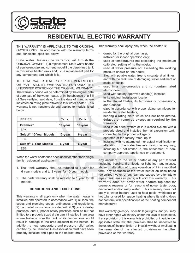
RESIDENTIAL ELECTRIC WARRANTYTHIS WARRANTY IS APPLICABLE TO THE ORIGINALOWNER ONLY. In accordance with the warranty termsand conditions specified below.
State Water Heaters (the warrantor) will furnish theORIGINAL OWNER, 1) a replacement State water heaterof equivalent size and current model if the glass-lined tankin this water heater leaks and, 2) a replacement part forany component part which fails.
THE STATE WATER HEATERS REPLACEMENT MODELOR PART WILL BE WARRANTED FOR ONLY THEUNEXPIRED PORTION OF THE ORIGINAL WARRANTY.The warranty period will be determined by the original dateof purchase of the water heater, or in the absence of a Billof Sale verifying said date, from the date of manufactureindicated on rating plate affixed to this water heater. Thiswarranty is not transferrable and applies to models listedbelow:
When the water heater has been used for other than singlefamily residential application;
1. The tank warranty shall be reduced to 1 year for6 year models and to 3 years for 10 year models.
2. The parts warranty shall be reduced to 1 year for allmodels.
CONDITIONS AND EXCEPTIONS
This warranty shall apply only when the water heater isinstalled and operated in accordance with 1) all local firecodes and plumbing codes, ordinances and regulations,2) the printed instructions provided with it, 3) good industrypractices, and 4) proper safety practices such as but notlimited to a properly sized drain pan if installed in an areawhere leakage from the tank or its connections wouldresult in damage to the area adjacent to the heater. Inaddition, a new temperature and pressure relief valve,certified by the Canadian Gas Association must have beenproperly installed and piped to the nearest drain.
SERIES Tank Parts
Premier® 10-year 10-yearEPXSelect® 10-Year Models 10-year 6-yearESXSelect® 6-Year Models 6-year 6-yearES6
This warranty shall apply only when the heater is:
• owned by the original purchaser;• installed for indoor operation only;• used at temperatures not exceeding the maximum
calibrated setting of its thermostat;• used at water pressure not exceeding the working
pressure shown on the heater;• filled with potable water, free to circulate at all times
and with the tank free of damaging water sediment orscale deposits;
• used in a non-corrosive and non-contaminatedatmosphere;
• used with factory approved anode(s) installed;• in its original installation location;• in the United States, its territories or possessions,
and Canada;• sized in accordance with proper sizing techniques for
residential water heaters;• bearing a rating plate which has not been altered,
defaced or removed except as required by thewarrantor;
• used in an open system or in a closed system with aproperly sized and installed thermal expansion tank;
• connected to the proper voltage or:• operated at the factory rated input;• installed with no attempted, nor actual modification or
alteration of the water heater’s design in any way,including but not limited to, the attachment of non-company approved appliances or equipment.
Any accident to the water heater or any part thereof(including freezing, fire, floods, or lightning), any misuse,abuse or alteration of it, any operation of it in a modifiedform, any operation of the water heater on desalinated(deionized) water, or any damage caused by attempts torepair tank leaks or parts, will void this warranty. Thiswarranty does not cover water heaters replaced forcosmetic reasons or for reasons of noise, taste, odor,discolored and/or rusty water. This warranty does notapply to water heaters used to heat pools, whirlpools orhot tubs or used for space heating where its sizing doesnot conform with specifications of the heating componentmanufacturer.
This warranty gives you specific legal rights, and you mayhave other rights which vary under the laws of each state.If any provision of this warranty is prohibited or invalid underapplicable state law, that provision shall be ineffective tothe extent of the prohibition or invalidity without invalidatingthe remainder of the affected provision or the otherprovisions of this warranty.

25
SERVICE AND LABOR RESPONSIBILITY
UNDER THIS LIMITED WARRANTY, THE WARRANTORWILL PROVIDE ONLY A REPLACEMENT WATERHEATER OR PART THEREOF. THE OWNER ISRESPONSIBLE FOR ALL OTHER COSTS. Such costsmay include but are not limited to:
a. Labor charges for service, removal, or reinstallation ofthe water heater or part thereof.
b. Shipping and delivery charges for forwarding the newwater heater or replacement part from the nearestdistributor and returning the claimed defective heateror part to such distributor.
c. All cost necessary or incidental for handling andadministrative charges, and for any materials and/orpermits required for installation of the replacementheater or part.
LIMITATION ON IMPLIED WARRANTIES
Implied warranties, including any warranty ofmerchantability imposed on the sale of this heater understate law are limited to one year duration for the heateror any of its parts. Some states do not allow limitationson how long an implied warranty lasts, so the abovelimitations may not apply to you.
CLAIM PROCEDURE
Any claim under this warranty should be initiated withthe dealer who sold the heater, or with any other dealerhandling the warrantor’s products. If this is not practical,the owner should contact: State Industries, Inc.,500 Lindahl Parkway, Ashland City, Tennessee 37015.Phone: 1.800.365.0024 or visit our website:www.stateind.com.
Replacement Parts may be ordered through authorizedservicers or distributors. Refer to your local Yellow Pagesfor where to call or contact State Water Heaters,500 Lindahl Parkway, Ashland City, TN 37015, phone:1.800.821.2017.
The warrantor will only honor replacement with identicalor similar water heater or parts thereof which aremanufactured or distributed by the warrantor.
Dealer replacements are made subject to in-warrantyvalidation by warrantor.
PROOF-OF-PURCHASE AND PROOF-OF-INSTALLATION DATE ARE REQUIRED TO SUPPORT
WARRANTY CLAIM FROM ORIGINAL OWNER. THISFORM DOES NOT CONSTITUTE PROOF-OF-PURCHASE OR PROOF-OF-INSTALLATION.
DISCLAIMERS
NO EXPRESSED WARRANTY HAS BEEN OR WILLBE MADE IN BEHALF OF THE WARRANTOR WITHRESPECT TO THE MERCHANTABILITY OF THEHEATER OR THE INSTALLATION, OPERATION,REPAIR OR REPLACEMENT OF THE HEATER ORPARTS. THE WARRANTOR SHALL NOT BERESPONSIBLE FOR WATER DAMAGE, LOSS OFUSE OF THE UNIT, INCONVENIENCE, LOSS ORDAMAGE TO PERSONAL PROPERTY, OR OTHERCONSEQUENTIAL DAMAGE. THE WARRANTORSHALL NOT BE LIABLE BY VIRTUE OF THISWARRANTY OR OTHERWISE FOR DAMAGE TO ANYPERSONS OR PROPERTY, WHETHER DIRECT ORINDIRECT, AND WHETHER ARISING IN CONTRACTOR IN TORT.
Should governmental regulations or industry standardsprohibit the Manufacturer from furnishing a comparablemodel replacement under this warranty, the Owner willbe furnished with the closest comparable water heatermeeting the then current governmental regulations andindustry standards. A supplementary fee may beassessed to cover the additional cost associated withthe changes made to meet applicable regulations andstandards.
IMPORTANT INFORMATION
Model Number
Serial Number
INSTALLATION INFORMATION
Date Installed
Company’s Name
Street or P.O. Box
City, State, and Zip Code
Phone Number
Plumber’s Name

26
NOTES:________________________________________________________________________________________________________________________________________________________________________________________________________________________________________________________________________________________________________________________________________________________________________________________________________________________________________________________________________________________________________________________________________________________________________________________________________________________________________________________________________________________________________________________________________________________________________________________________________________________________________________________________________________________________________________________________________________________________________________________________________________________________________________________________________________________________________________________________________________________________________________________________________________________________________________________________________________________________________________________________________________________________________________________________________________________________________________________________________________________________________________________________________________________________________________________________________________________________________________________________________________________________
NOTES

27

28
500 Lindahl Parkway, Ashland City, TN 37015Phone: 800-821-2017 Fax: 800-644-9306
www.statewaterheaters.com