Embed Size (px)
Citation preview

Instruction Manual
AEA MORSE
MEMORY KEVER
MODEL CK-l

LIMITED WARRANTYADVANCED ELECTRONIC APPICATIONS, I~IC. warrants to the anginal purchaser that this product sholl be free
from defects In material or workmanship for ninety days from the date of anginal purchase In order 10 obtain
warranty service: (1) Complete and mall the warranty registration card to Advanced Electronic Applications Inc ,and (2) Send written notification to the address below as soon a.s pOSSible after discovering a pOSSIble cipfccl
Advanced Electronic Applications IncAttention: Service Department
Bldg '0,2006 - 196th S W
Lynnwood. Wa. 98036
The written notification must include a copy of the invoice. Include a description qf the defective part or condition.
with details of the electrical connections to associated equipment and list such equipml"lt. Please enclose your
name, phone number, and address. Shipping charges for any parts or units submitted for replacement under thiswarranty must be paid by the purchaser.
Correct maintenance, repair, and use are important to insure proper performance form this product. Carefully readthe instruction manual. This warranty does not apply to any defect AEA determines is caused by (1) impropermaintenance or repair. including the installation of parts or accessories that do not conform to the qUilltiy andspecification of the original parts; (2) misuse. abuse. neglect. or Improper Install(ltion: (3) Jccrdcntal or intentionaldamage.
All implied warranties, if any. terminate ninety days from the date of or"lg'lnalpurchase. AEA is not responsible fordamage to other equipment or property or any other consequential or incidential damage of any kind whether basedon contract. negligence. or strict liability. Maximum liability shall not. in any case. exceed the purchase price of theunit
The foregoing constitutes AEAs entire obligation with respecl to this product The Original purchaser and any user
or owner shall have no other remedy and no claim for incidental or consequential damages Some states do not allowlimitations on how long an implied warranty lasts or do not allow the exclusion of incidental or conse::wentla!damages, therefore. the above limitations and exclusions may not apply to you
This warranty gives specific legal rights. You may also have other rights which vary from state fa state
Specifications subject to change without notice or obligation .
~
ADV ANCED ELECTRONIC APPLICATIONS, INC.
P.O. Box 2160
Lynnwood, Washington 98036 USA
(206) 775·7373
COPYright 1980 by ADVANCED ELECTRONIC APPLICATIONS. INC.All rights reserved. No part 01 this book may be reproduced or utilized in anyform or by any means, without permission in writing from the publisher

.,.,
TABLE OF CONTENTS
CK-1 WIRING INSTRUCTIONS 1KEYING TRANSISTORIZED TRANSCEIVERS 1
OPERATIONI. GENERAL 2
II. KEYER 2
1. SPEED CHANGE AND SET , 2PRESET SPEEDS 2VARIABLE SPEED ADJUSTMENT.: 3
2. SIDETONE CHANGE 3
3. AUTOMATIC OR SEMI-AUTOMATIC (BUG) OPERATION 34. DOT-SPACE, DASH-SPACE RATIOS (WEIGHTING) 35. DOT AND DASH MEMORIES 56. TRANSMITTER TUNING 67. MiSTAKES 6
III. MEMORY OPERATIONS 61. MEMORY LOCATIONS 62. MEMORY MESSAGE LOAD 7
REAL TIME MESSAGE LOADING 7AUTOMATIC MEMORY LOAD 7
3. MEMORY ERASE 8

4. MEMORY RETENTION 85. MAXIMUM LOADING SPEED 86. SERIAL NUMBER LOAD AND SET 97. EXTRA WORD OR CHARACTER SPACES , 108. MEMORY FULL WARNING ' ' 10
9. SEMI-AUTO (BUG) MEMORY LOAD 10IV. MEMORY SEND OPERATION 11
1. SENDING A MESSAGE 112. INTERRUPTING AND RESTARTING A MESSAGE 113. SERIAL NUMBERS IN MEMORY SEND 11
V. EDITING MESSAGES IN MEMORY ' 121. EDITCAPABILITIES 122. INSERTION 123. DELETION 12
GENERAL INFORMATIONSCHEMATIC 14PARTS PiCTORIAL 15PARTS LIST 16APPENDIX A 18CODE 18WARRANTY 'c' ••• INSIDE BACK COVERPROGRAMMING KEy 'BACK COVER

CK-1 WIRING INSTRUCTIONS
TIP POSITIVE ~
~NEGATIVE~ 5.5mm/2.ommSLEEVE NON - SHORTING
1- COMMON2-DASH3-DOT4-BLANK5-BLANK
2
400 5
° °1""'°3
~COMMON
BIPOLAR ~\S})OUTPUT
Power Plug Paddle Connection Keyer output
KEYING TRANSISTORIZED TRANSCEIVERSSome transistorized transceivers such as the ICOM 701 and the Ten-Tee
line require a slight modification of the AEA keyer. With this modification, areed relay is not required for proper keying.
If the CK-1 does not key your transceiver, check your transceivers key inputpolarity with respect to chassis ground. If positive, modify the unit as follows:
A. Remove the keyer from its case and locate the diode closest to thespeaker (D4).
B. Solder a jumper across this diode.C. Reassemble the keyer.
IMPORTANT!If the keyer is to be used with a transceiver or transmitter with negative
keying polarity, such as avacuum tube transmitterwith grid blocked keying, itis necessary to remove this jumper.
1

OPERATIONI. General
The AEA Keyer Model CK-1 has been designed for the serious CW operator.It features a versatile memory load and edit capability, automatic serialnumber, rapid CW speed changes and full weighting control.II. Keyer1. Speed Change And Set
Two methods of CW speed control are available, variable and preset.Preset Speeds
Two presetable sQ§!eds may be stored and quickly recalled. To store speed"A", press 00 [§] Il:!J [E!], where N N is the two diqj! speed in wpm desired.Similarly, for storing speed "B", press 0 0 lID [E!] 1l:!J.
The keyer will be set to the last speed entered.When the keyer is turned on, speeds "A" and "B" are initialized to 20 and
30 wpm respectively.To recall speed "A", press 0[§] and to recall speed "B", press0lID.Example: To store 5 and 15 wpm in speeds "A" and "B":
Press 0 0llil [Q] [§]o 0 lID OJ [§] :
Now, to change from 15 wpm to 5 wpm, press 0 [§] . To change back to 15,press 0 lID . '
2
\
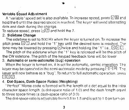
Variable Speed AdjustmentA "variable" speed set is also available. To increase speed, press 0 [§] and
hold the 6 until the desired speed is reached. The keyer will send alternatingdots and dash during the change.To reduce speed, press 0 [II and hold the 7.
2. Sidetone ChangeThe sidetone is set to 500 Hz when the keyer is turned on. To increase the
pitch press 0 ITJ and hold the "1" key until the desired tone is reached. Thetone may be lowered by pressing 0twice and holding the "1" i.e., 0 G ITJ .
The pitch of the sidetone when the "1" key is released will be the pitch ofthe CW sidetone. The pitch of the keypad feedback tone will be lower.3. Automatic or semi-automatic (bug) operation
When the keyer is turned on, it is set for automatic, iambic operation Thekeyer may be operated in the semi-automatic mode by pressing 00[§] . The
ke~r will now behave as a "bug". To return to full automatic operation, press0~[II .4. Dot-Space, Dash-Space Ratios (Weighting)
"Perfect" Morse code is formed with the length of a dot equal to the intracharacter space length, (a dot-space ratio of 1.0) and the dash length equalto three space times (a dash-space ratio of 30).
The dot-space ratio is adjustable from 0.5 to 1.5 alld is set to 1.0 on turn-on.
3
(
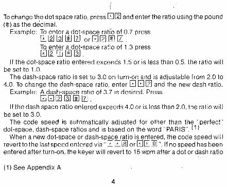
Tochange the dot space ratio, press GJ~ and enter the ratio using the pound(:jj:) as the decimal.. Example: To enter a dot~space rati'o of 0.7 press
GJ ~ [Q] lliJ[ZJ 0r GJ ~ lID [ZJ .
To enter a dot-space ratio of 1.3 pressGJ ~ ITJ lID @] .
If the dot-space ratio entered exceeds 1.5 or is less than 0.5, the ratio willbe set to 1.0.
The dash-space ratio is set to 3.0 on turn-on and is adjustable from 2.0 to4.0. To change the dash-space ratio, enter GJ GJ ~ and the new dash ratio.
Example: A dash-s.2§lceratio of 3.7 is desired. PressGJGJ~ ~ lID [ZJ.
If the dash space ratio entered exceeds 4.0 or is less than 2.0, the ratio willbe set to 3.0.
The code speed is automatically adjusted for other than the "perfect"dot-space, dash-space ratios and is based on the word "PARIS", (1)
When a new dot-space or dash-space ratio is entered, the code speed willrevert to the last speed entered via" GJGJllil or GJGJ[ill ". If no speed has beenentered after turn-on, the keyer will revert to 15 wpm after a dot or dash ratio
(1) See Appendix A
4

',!fl,
change. This will have the largest effect if the variable speed change featurehas been used before changing the ratio.5. Dot and Dash Memories
The selectable dot and dash memories are enabled on keyer turn-on. Thedot memory allows insertion of a dot during a string of dashes. For example.the lefter "0" could be sent as follows:
Keyer Output
Dash Contact ----I
Operated dUring fl1this IntervalIDot Contact -----,--- ; I
I 1 III
I,I
rel~ased duringthis Interval
,IIII
Closed
Open
Closed
Open
The dash memory operates in the same fashion, allowing the insertion of adash in a string of dots.
To disable the dot memory, press GJ ~ .
To enable the dot memory, press GJ GJ ~ .
To disable the dash memory, press GJ @] .
To enable the dash memory, press GJ GJ @] .
5

Full iambic operation is available with the dot and dash memories enabledor disabled. 'This feature is useful for generating characters with alternatingdots and dashes like the peri6d and the letter "C". To utilizethis feature, hold both the dot and dash paddles.6. Transmitter Tuning
To allow transmitter tuning, the keyer output transistors will be operatedupon pressing G G [ill . The "5" must be released before the keypad tone iscompleted. Tuning will be terminated by pressing any keypad button oroperating the dot or dash paddle.
The tune feature only operates in the keyer-memory send mode.7. Mistakes
Incomplete, undesired entries may be terminated by pressing 00 . Unacceptable entries will be ignored. For example, if a speed change were entered G G [ill [2JG, the result will be no speed change.
III. Memory Operations1. Memory Locations
The AEA CK-1 keyer has ten separate, variable length memory locations.The total memory length is about 500 characters (the actual length is dependent on the lengths of the characters, the length and number of pauses, etc.),which may be divided into the ten locations in any fashion. Each memorylocation length is automatically adjusted during message loading.
6

'~,
\
2. Memory Message LoadTwo methods of memory loading are available, Real Time loading and Auto
matic character and word space loading. In both modes memory loading doesnot begin until the first character is started. This prevents the undesirablepause. at the beginning of the message playback. Messages may also beloaded in semi-automatic (bug) mode.Real Time Message Loading
To select Real Time message loading, set the mode switch to "MemoryLoad" (toward the connector panel) and press GJ [ill . Select the messagelocation desired, 0 through g, and press the location digit. Memory loadingwill begin with the first characters and all pauses in sending will be loadedas sent (pauses use memory space). When message loading is complete,press 00 to terminate the message load.Automatic Memory Load
The Keyer is set to automatic memory load on turn-on. If real-time load hasbeen selected, automatic memory load may be re-selected by pressingGJ GJIill when the mode switch is in the memory load position.
In automatic message loading, a pause in sending longer than two spacelength records a character space (three intra character spaces) If the pauseis longer than five space lengths, a word space is recorded (seven intracharacter spaces), loading then stops until the next character is started.
7

To record q. message, set the mode switch to Memory Load. toward front of
the unit. press the message location qi~t. key in the message. and terminatethe message with the pound sign key UtJ .
Example: To store a message in memory location 5, set the mode switch to
Memory Load and press lliJ . Now enter the mess~e with the key.IMPORTANT: After the message is entered press UtJ to signal the end of themessage load.3. Memory Erase
Power is supplied to the memory from the 12V source.Operation of the off-on switch erases the entire memory. however the unit
is designed to be left on continuously.To erase one of the memory locations. switch to Memory Load (toward the
connector panel). press the location number and then 00 . The entire message in that location will be erased.
Example: Erase messages 3 and 7. set mode to Memory Load, press@] 00 [1] 00 or [1] 00 @] 00
4. Memory RetentionWhen 12V power is first applied the memory will contain random characters.
These random characters should be erased (see previous section) before highspeed loading is attempted. Power must be left on to maintain memory.5. Maximum Loading Speed
8
},f
}
),

Loading'speeds up to 99 wpm are permissable if memory locations higherthan the location being loaded are empty or contain short messages. If,for example, memory location 5 contains about 300 characters and high speedmessage loading is attempted in locations 0 through 4 a pause between everytwo dots and/or dashes will occur. To prevent this either reduce loadingspeed: erase the long message, or load the new message into a highermemory location.6. Serial Number Load and Set
An automatically incremented serial number may be inserted anywherein any of the ten messages. It may also be inserted as many times as desiredwithin a message. The serial number is incremented just as the messageis completed.
To insertthe automatic serial number during the loading of a message pressEJ[Q]. Insertion of a serial number in real time memory load will halt the realtime loading of the pause. The next keyed character will restart pause loading.
When the power switch is turned on, the serial number is set to 01.If the serial number has incremented, it may be reset to 01 in the memory
load mode by pressing EJ EJ [Q] .
The serial number may be changed to any number between 01 and 9999 inthe keyer-memory send mode by pressing EJ EJ [Q] WJ WJ WJ WJ 00 whereN N N N is the one to four digit serial num"ber desired.
9

Example: A startina,serial number of 971 is desired. Press,[~J0 [Q] lliHIJ []] 00 .The next serial number ~ent will be 971.
7. Extra Word or Character SpacesIn the automatic memory load mode, one word space is loaded after keying
is halted. If desired, additional word (7 space lengths) or character (3 spacelengths) may be entered. Each time 0 0lliJ is pressed an additional wordspace will be loaded and each time 0lliJ is pressed an additional characterspace will be loaded.
Insertion of a word or character space in real time memory loading will stopthe real time load of a pause, the next keyed character will restart pauseloading.S.Memory Full Warning
When the memory is completely full, the CW sidetone pitch will decrease.At this point, load is automatically terminated. If further loading is desired, itwill be necessary to erase one of the other messages.9. Semi-Auto (bug) Memory Load
Messages may be entered in the semi-automatic mode. During memorysend, the messages will be sent with the selected dot and dash ratio andthe keyer will revert to automatic operation.
10
•...

If the paddle has contact bounce it will be necessary to connect a 1.0mf cap across the dash contacts to prevent loading of extra dashes in semiautomatic mode.
IV. Memory Send Operation1. Sending A Message
To start any of the ten messages. set the mode switch to Keyer-Memory
Send (away from the connector panel) and press the digit of the desired message location. The message will start when the key pad button is released
Example: To start message 6, press and release [§] .2. Interrupting and Restarting A Message
A message being sent from memory may be interrupted by pressing thepound sign key 00 or by tapping either of the keyer paddles. The Memorykeyer then enters normal keyer operation and a hand keyed message maybe sent.
The interrupted message may either be restarted by pressing the digitof the message or resumed from the point of interruption by pressing 0[§] .If the message has completed, pressing 0 [§] will start the next message.except for message 9.3. Serial Numbers in Memory Send
The serial number will be automatically inqemented when a message containing a serial number is completed. If the message is interrupted. the serial
11

number will not be incremented.
A new star'tir:..g,serial number may be loaded, in memory send mode bypressing B B lQJ [t1J [t1J [t1J [t1J rID , where N N N N is the new, one to fourdigit, serial number.
The previous serial number may be repeated by pressing, in memory sendmode, B[Q] before starting the message. Each operation of B[Q] will reducethe serial number by one.
v. Editing Messages in Memory1. Edit Capabilities
Messages in memory may have additions placed anywhere in the messageand deletions from any point in the message to the end of the message.2. Insertion
To insert additional text in an existing message, play the message inmemory send mode and halt the message at the desired point with eitherpaddle or the pound rID key. Switch to memory load, press B [ill and keyin the desired addition. Switch back to memory send without pressing rID .
If the insertion is at the very beginning of a message, switch to memoryload, press the digit of the message location and key in the desired addition,then switch back to memory send without pressing rID .3. Deletion
During message loading, operation of the pound rID key signals the end of
12

'1_\11,
message and erases the previous message from that point to the end of thatmessage location. This may be used for partial message deletion as well ascomplete message erasure.
For a partial deletion, in memory send mode, play the message to thedesired point and halt it with either the paddle or pound 00 key. Switchto memory load, and pressGJ [§] , At this point additional message text maybe entered if desired Press the pound 00 key. The message will be terminated at this point and the remaining text of the message will be deleted.
GENERAL INFORMATION
SCHEMATICPARTS PICTORIALPARTS LISTAPPENDIX ACODEWARRANTYPROGRAMMING KEY
13

SCHEMATIC
14

ONO ~m•I~+~ '-lOWER 1'3 fj u @~?UI
J2-a DOT Cl +C7 C6
UU
J2-2 O~" ~
?U3 I
J2-1 GNO
~=ffiB=
XI
VOLE U4
02 '
R4 @I ~SPI tJF
--[BD-RI @)R R3
@J 0OUTPJU;Cb.J Q2 10 © -~
C2 0 0 U LOAD •-<IQD- -<IQD---' ---[BD-C4SEND•.•..
PARTS PICTORIAL
15

CK-1 PARTS LIST
C1 0.0047 mfC2,9,10 0.001C3.5.8. 11.12 0.1 mfC4 0.01 mfC6.7 10 mf or 6.8 mf
50v disc cer500v disc cer
50v disc cer50 v disc cer25v dipped tantalum
01.2.5 IN4448 or IN414803,4 IN400606 IN4003
01.3 2N390402 MPS656104 MPSA9205 MPSA42,
16

R1,2 12 OhmsR3,8 330 OhmsR4 1K OhmsR5 240 Ohms
R6,12,13 47K OhmsR7 2.4K OhmsR9 10K Ohms
R1 0, 11 1K Ohms
;SW 5% Carbon Camp1J,W5% Carbon Camppot w switch, audio taper1J,W5% Carbon Camp
1J,W5% Carbon Camp1J,W5% Carbon Camp1J,W5% Carbon Camp1J,W5% Carbon Camp
U1 CD4044B or MC14044BU2 A EA 1980 M M KU3 2114
U4 7805 Voltage regulator
X1 4.00 MHz XtalS1 Part of R4S2 SPST Slide SW
17

PROGRAMMING KEYMORSE MEMORY KEYER
8 KEYER MEMORY ISEND
U 0T I I'T Go IN T I * **
I MEMORY LOADoI
GITI * **
1 Tone Up2 Q) Dot Ratio3 gOat M. Off
en
4 en ~ Dash M. Off5 ~~ Resume
6 ~~ Speed7 u Speed
8 "* A Speed9 CJ) 8 Speedo SIN Repeat
'If Halt
Tone DownDash RatioDot M. OnDash M. OnTuneSemi-AutoAutoSet ASet 8SIN Set
Tone Up
c:: Dot Ratio.2 Dot M. Off
•• ~ Dash M. Off~ .3 Edit (Insert)
CD Q) SpeedCJ)Cl~ Speed.8 Char. SpaceCJ) Real Time
SIN Loadf--End
Input
Tone DownDash RatioDotM.OnDash M. On
Semi-AutoAuto
Word SpaceAuto LoadSIN = 1