Embed Size (px)
Citation preview

Operating instructions NeoFlow Pressure Reducing Valve
DN200 – DN300
2
Disclaimer
The technical data is not binding. It does not constitute expressly warranted characteristics. And neither guaranteed properties nor guaranteed durability. It is subject to modification. Our General Terms of Sales apply.
Observe instruction manual
The instruction manual is part of the product and an important element within the safety concept.
► Read and observe instruction manual.
► Always have instruction manual available by the product.
► Give instruction manual to all subsequent users of the product
3
CONTENTS
1 PRODUCT DESCRIPTION ....................................................................................................... 6 1.1 Intended Use ............................................................................................................................ 6 1.2 EC Manufacturer's declaration .................................................................................................. 6 1.3 PRESSURE REDUCING VALVE (PRV) CONFIGURATION................................................................. 7
1.3.1 METHOD OF OPERATION ...........................................................................................................................7 1.3.2 P&ID ...........................................................................................................................................................7
1.4 PRESSURE RATINGS & PERFORMANCE ...................................................................................... 8 1.5 FLANGE & SIZING DATA ............................................................................................................ 8 1.6 NAMEPLATE INFORMATION ...................................................................................................... 9 1.7 BILL OF MATERIALS – PRESSURE REDUCING ASSEMBLY............................................................ 10 1.8 BILL OF MATERIALS – VALVE BODY .......................................................................................... 12 1.9 BILL OF MATERIALS – CONTROL BLOCK .................................................................................... 14 1.10 BILL OF MATERIALS – PRESSURE REDUCING PILOT (PR1) .......................................................... 15 1.11 BILL OF MATERIALS – SPEED CONTROL .................................................................................... 16
1.11.1 SEAL KITS ..................................................................................................................................................17 1.11.2 PRESSURE SENSE PORTS ..........................................................................................................................17 1.11.3 PRESSURE CONTROLLER COMPATIBILITY .................................................................................................18
1.12 RECOMMENDED TOOLS AND CONSUMABLES .......................................................................... 18 1.12.1 INSTALLATION/MAINTENANCE TOOLS ....................................................................................................18 1.12.2 LUBRICATION & THREAD SEALANT ..........................................................................................................18
2 INSTALLATION ................................................................................................................... 19 2.1 TRANSPORT AND HANDLING .................................................................................................. 20 2.2 SITE SELECTION....................................................................................................................... 21
2.2.1 BYPASS LINE .............................................................................................................................................21 2.2.2 PERMITTED VALVE ORIENTATIONS ..........................................................................................................23 2.2.3 PERMITTED SPATIAL DIMENSIONS...........................................................................................................24
2.3 PILOT SPRING OPTIONS .......................................................................................................... 25 2.4 VALVE INSTALLATION ............................................................................................................. 26 2.5 VALVE BOLT TORQUES ............................................................................................................ 29 2.6 FLANGE ADAPTORS................................................................................................................. 29
3 COMMISSIONING ............................................................................................................... 30 3.1 NeoFlow EXTERNAL COMPONENTS ......................................................................................... 30 3.2 SETTING SPEED CONTROL VALVE ............................................................................................. 31 3.3 INITIAL PRESSURISING ............................................................................................................ 32 3.4 SETTING PRV DOWNSTREAM PRESSURE .................................................................................. 34
3.4.1 WITH HYDRANT ........................................................................................................................................34 3.5 ADJUSTING THE SPEED CONTROL ............................................................................................ 36
4 MAINTENANCE .................................................................................................................. 37 4.1 DEPRESSURISING CONTROL SYSTEM ....................................................................................... 38 4.2 LIVE STRAINER & CONTROL SYSTEM FLUSHING........................................................................ 39 4.3 VALVE REMOVAL .................................................................................................................... 41 4.4 CONTROL SYSTEM REMOVAL .................................................................................................. 43 4.5 CONTROL SYSTEM SERVICING ................................................................................................. 44
4.5.1 CONTROL BLOCK ......................................................................................................................................44 4.5.2 PRV PILOT .................................................................................................................................................45
4.6 MAIN BODY ............................................................................................................................ 47 4.6.1 SHUT-OFF SEAL SERVICING ......................................................................................................................50
5 TROUBLESHOOTING ........................................................................................................... 52 5.1 DIAGNOSTICS ......................................................................................................................... 52

4
IMPORTANT INFORMATION PLEASE READ BEFORE PROCEEDING
THIS INFORMATION PROVIDES GUIDANCE FOR THE INSTALLATION AND MAINTENANCE OF THE NeoFlow Pressure Reducing Valve AND IS INTENDED FOR USE BY COMPETENT PERSONNEL ONLY.
DO NOT WORK ON THE VALVE WHEN PRESSURISED. ONLY A SMALL NUMBER OF MAINTENANCE ACTIVITIES CAN BE COMPLETED DURING LIVE OPERATION. THESE ARE OUTLINED IN SECION 4.
FAILURE TO FOLLOW THE PROCESSES IN THIS MANUAL MAY INVALIDATE THE PRODUCT WARRANTY. PLEASE CONTACT GF Piping Systems IF YOU ARE IN ANY DOUBT.
THE INFORMATION PROVIDED IN THIS DOCUMENT IS ACCURATE AT THE TIME OF PUBLICATION. HOWEVER, IT MAY BE SUBJECT TO CHANGE. THEREFORE, PLEASE CONTACT GF Piping Systems TO ENSURE YOU HAVE THE LATEST VERSION.
Achilles UVDB registration number 205390
5
Abbreviations
EPDM Ethylene Propylene Diene Terpolymer
GCR GCR Tech Pressure Controller
HWN Halma Pressure Controller
P&ID Piping and Instrumentation Diagram
PCS Control Space Pressure
PN Pressure Nominal
PRV Pressure Reducing Valve
SS Stainless Steel
WRAS Water Regulations Advisory Scheme
6
1 PRODUCT DESCRIPTION
1.1 INTENDED USE
The pilot controlled NeoFlow pressure reducing valve from GF Piping Systems was conceived for
the automatic pressure and flow control in networks for the supply and distribution of water. The
NeoFlow pressure reducing valve is designed to fit between standard PN10 / PN16 in a wafer-type
arrangement. It is also compatible with ANSI150 class flanges.
Foreseeable misuse: The NeoFlow pressure reducing valve may not be used as a pure shut-off valve.
Media other than water as well as water containing an amount of disinfectant may only be used in
consultation with a contact partner from GF Piping Systems. The use of solid matter in the medium
can affect the function of the NeoFlow pressure reducing valve. For this reason, use is only
recommended with an upstream strainer.
1.2 EC MANUFACTURER'S DECLARATION
The manufacturer Georg Fischer Rohrleitungssysteme AG, 8201 Schaffhausen (Switzerland)
explains that the NeoFlow pressure reducing valve fully complies with the standard “EN 1074-5
Valves for water supplies.” If the overall system does not comply with the requirements of an EC
directive, then putting the NeoFlow pressure reducing valve is prohibited until the conformity of the
overall system with the EC directive has been declared. Fittings Involved standards NeoFlow
Pressure reducing valve EN 1074-5 Changes to the fittings that could affect the stated technical data
and the intended use, void this manufacturer's declaration. Additional information can be found in
"GF planning fundamentals.”
7
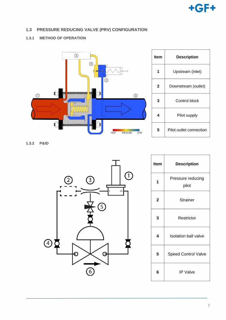
1.3 PRESSURE REDUCING VALVE (PRV) CONFIGURATION
1.3.1 METHOD OF OPERATION
Item Description
1 Upstream (inlet)
2 Downstream (outlet)
3 Control block
4 Pilot supply
5 Pilot outlet connection
1.3.2 P&ID
Item Description
1 Pressure reducing
pilot
2 Strainer
3 Restrictor
4 Isolation ball valve
5 Speed Control Valve
6 IP Valve
8
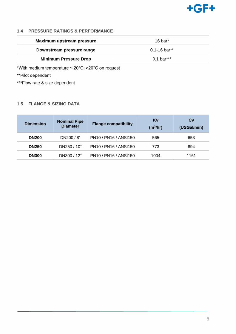
1.4 PRESSURE RATINGS & PERFORMANCE
Maximum upstream pressure 16 bar*
Downstream pressure range 0.1-16 bar**
Minimum Pressure Drop 0.1 bar***
*With medium temperature ≤ 20°C; >20°C on request
**Pilot dependent
***Flow rate & size dependent
1.5 FLANGE & SIZING DATA
Dimension Nominal Pipe
Diameter Flange compatibility
Kv
(m3/hr)
Cv
(USGal/min)
DN200 DN200 / 8” PN10 / PN16 / ANSI150 565 653
DN250 DN250 / 10” PN10 / PN16 / ANSI150 773 894
DN300 DN300 / 12”
PN10 / PN16 / ANSI150 1004 1161

1.6 NAMEPLATE INFORMATION
Manufacturer Oxford Flow
Manufacturer’s town and country Oxford, UK
Regulator type Pilot-operated pressure reducing valve
Standard EN1074
Body Material POM-C
Nominal size DN DN0200-DN300
Allowable pressure PS 16 Bar(g) @ 20°C
Allowable incidental pressure 1.1 x PS
Continuous Operating temperature range
≤ 20°C; >20°C on request
Flow coefficient Cv See ‘Pressure Rating & Performance’
Leakage class EN 12266-1 Rate A
Ports G1/4 (BSPP)
Nameplate Key Data Definition Example
aaa Nominal size (DN) (DN)100
bbbbbbbbb Serial number IP2012345
cccc Year of Manufacture 2020
10
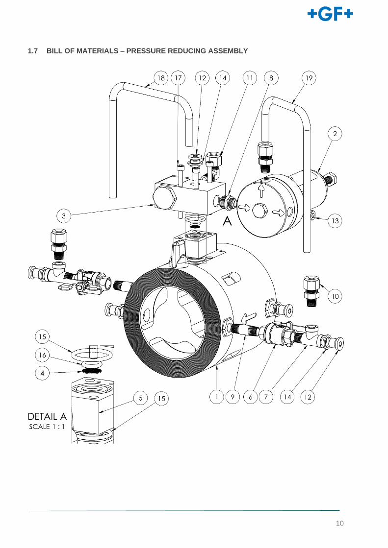
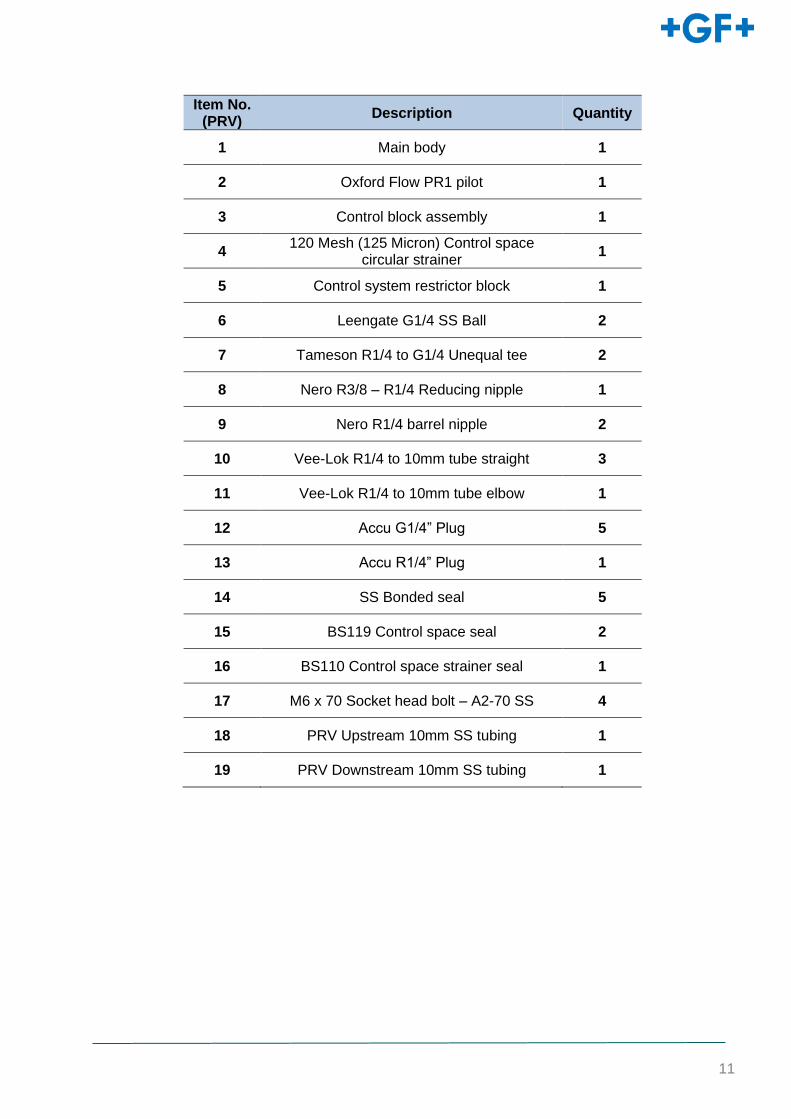
1.7 BILL OF MATERIALS – PRESSURE REDUCING ASSEMBLY
11
Item No. (PRV)
Description Quantity
1 Main body 1
2 Oxford Flow PR1 pilot 1
3 Control block assembly 1
4 120 Mesh (125 Micron) Control space
circular strainer 1
5 Control system restrictor block 1
6 Leengate G1/4 SS Ball 2
7 Tameson R1/4 to G1/4 Unequal tee 2
8 Nero R3/8 – R1/4 Reducing nipple 1
9 Nero R1/4 barrel nipple 2
10 Vee-Lok R1/4 to 10mm tube straight 3
11 Vee-Lok R1/4 to 10mm tube elbow 1
12 Accu G1/4” Plug 5
13 Accu R1/4” Plug 1
14 SS Bonded seal 5
15 BS119 Control space seal 2
16 BS110 Control space strainer seal 1
17 M6 x 70 Socket head bolt – A2-70 SS 4
18 PRV Upstream 10mm SS tubing 1
19 PRV Downstream 10mm SS tubing 1
12
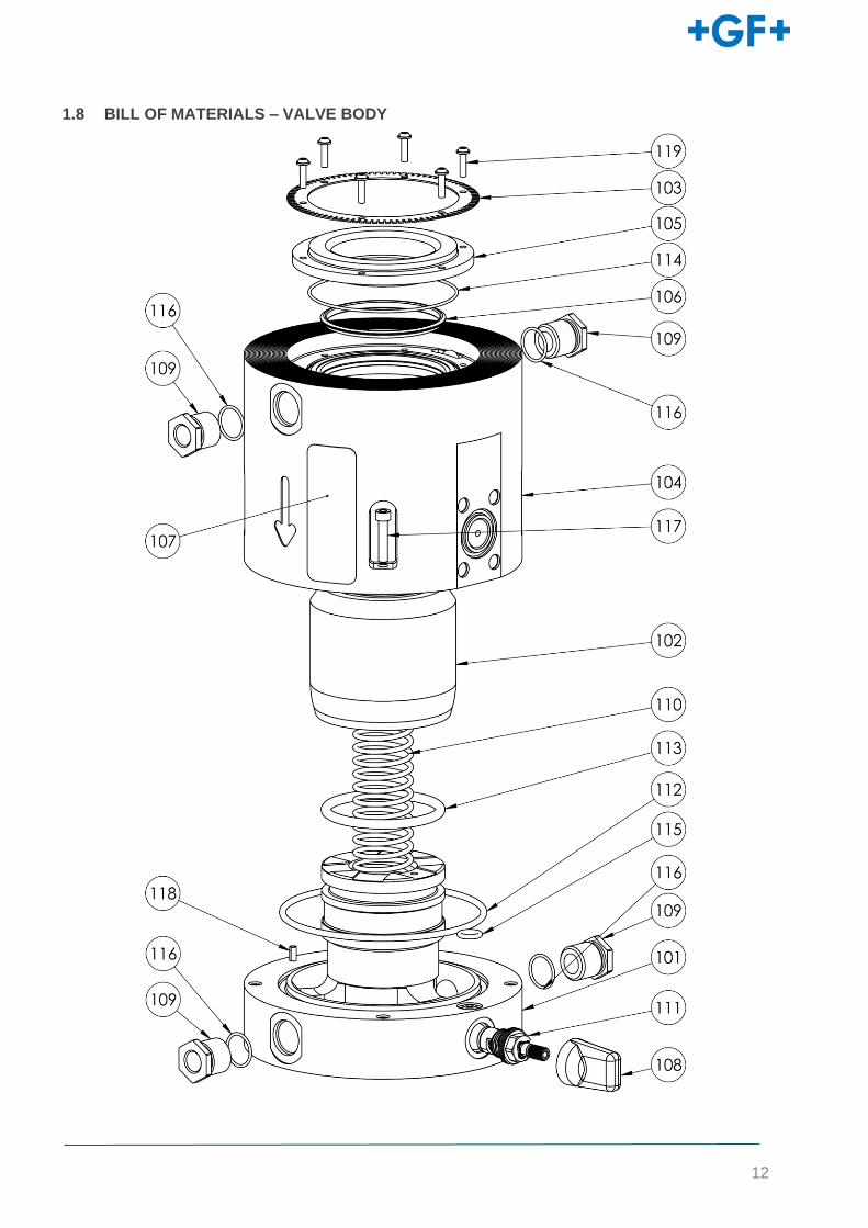
1.8 BILL OF MATERIALS – VALVE BODY
13
Item No.
Description Quantity
101 Core 1
102 Cap 1
103 Strainer 1
104 Casing 1
105 Inlet 1
106 Shut off seal 1
107 Nameplate Sticker 1
108 Isolation valve handle 1
109 M20 x 1.5 to G1/4 Bulkhead 4
110 Spring 1
111 Geann – G3/8 quarter turn ceramic
cartridge valve 1
112 Core seal 1
113 Primary shaft seal 1
114 Inlet 1
115 BS110 Control space seal 1
116 BS017 Bulkhead seal 4
117 Socket head bolt – A2-70 SS x
118 ∅4 x 18mm ISO8750 Roll pin – A1 SS 1
119 Bossard Delta PT Self Tapping Screw –
A2 SS x
14
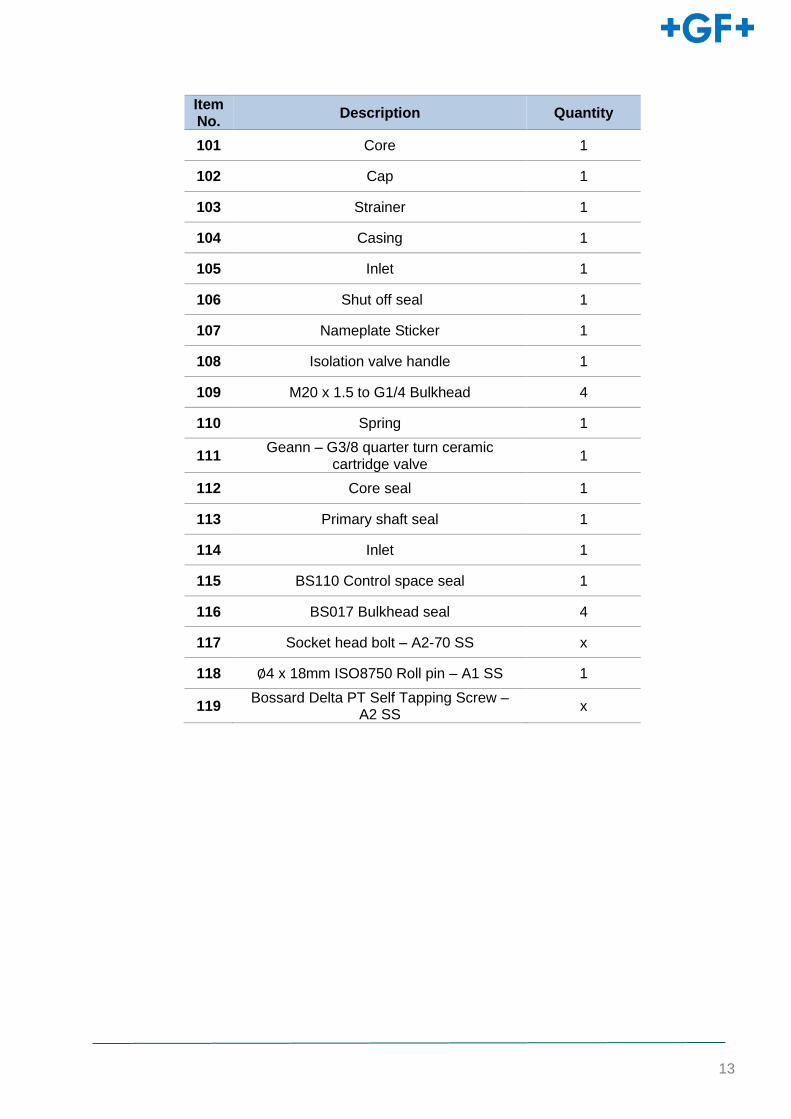
1.9 BILL OF MATERIALS – CONTROL BLOCK
Item No. Description Quantity
201 Control Block 1
203 60 Mesh Strainer 1
204 Control block strainer plug 1
205 BS119 Strainer 1
15
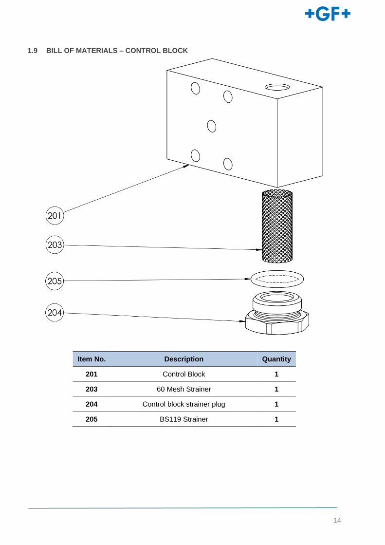
1.10 BILL OF MATERIALS – PRESSURE REDUCING PILOT (PR1)
Item No.
Description Quantity
301 PR1 Pilot Base 1
302 Diaphragm Housing 1
303 Spring Case 1
304 Diaphragm Support 1
305 Actuator 1
306 Upper Spring Guide 1
307 Diaphragm 1
308 G1/4 Pilot base plug 1
309 Pilot setpoint bolt (60mm) 1
310 PR1 Pilot Nameplate Sticker 1
311 Pilot Primary Spring 1
312 Pilot Actuator Spring 1
313 Pilot Diaphragm Bolt 1
314 Pilot base seal 1
315 Pilot base plug seal 1
316 M6 Flanged torque nut 1
317 M6 x 40 Socket head bolt – A2-70
SS 8
318 M10 Thin Hex Nut – A2-70 SS 1
319 M10 Spring colour indication
washer – Plastic/A2 SS 1
320 Actuator Pin 1
321 ∅3 x 10mm ISO8750 Roll pin – A1
SS 2
16
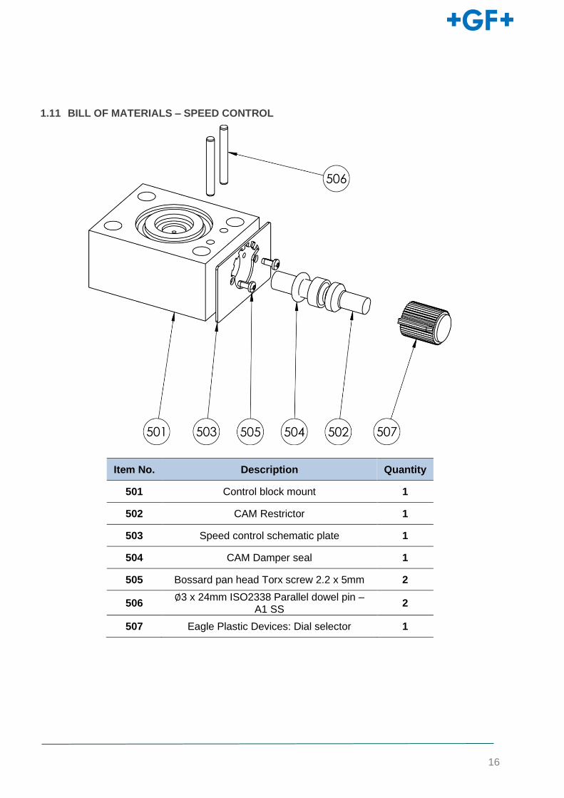
1.11 BILL OF MATERIALS – SPEED CONTROL
Item No. Description Quantity
501 Control block mount 1
502 CAM Restrictor 1
503 Speed control schematic plate 1
504 CAM Damper seal 1
505 Bossard pan head Torx screw 2.2 x 5mm 2
506 ∅3 x 24mm ISO2338 Parallel dowel pin –
A1 SS 2
507 Eagle Plastic Devices: Dial selector 1
17
1.11.1 SEAL KITS
Valve Size Seal Kits (inc. all O-Rings)
DN200 173021008
DN250 173021009
DN300 173021010
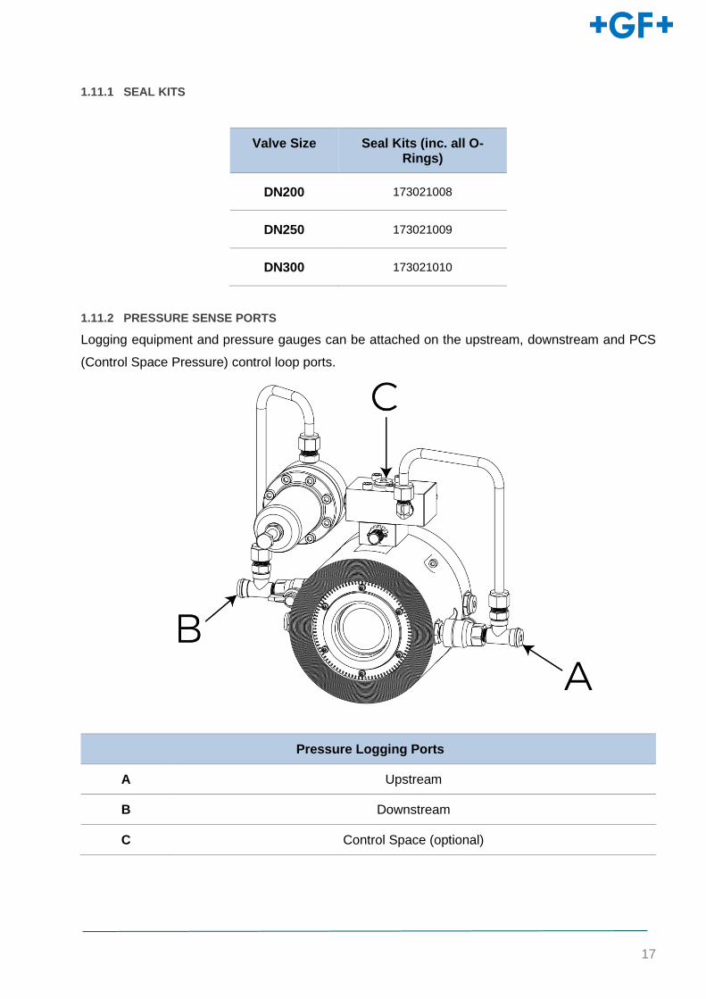
1.11.2 PRESSURE SENSE PORTS
Logging equipment and pressure gauges can be attached on the upstream, downstream and PCS
(Control Space Pressure) control loop ports.
Pressure Logging Ports
A Upstream
B Downstream
C Control Space (optional)
18
1.11.3 PRESSURE CONTROLLER COMPATIBILITY
Controller Compatible Comments
I20 YES
Replace pilot and control block with i20 system. Addition
connection ports provided on request to connect to i20
controller
GCR YES Replace pilot set bolt with an M10 controller bolt
HWM YES
1.12 RECOMMENDED TOOLS AND CONSUMABLES
1.12.1 INSTALLATION/MAINTENANCE TOOLS
• Spanners/sockets (full set)
• Flat head screwdrivers
• Torque wrenches
• Allen/hex keys (full set, ball-ended)
1.12.2 LUBRICATION & THREAD SEALANT
Lubrication
The manufacturer approved lubricant for all static seals is any generic WRAS approved silicone
grease, for instance SGM494.
The manufacturer approved grease for all dynamic seals is Molykote 111 (WRAS approved).
Thread Sealants
The manufacturer approved thread sealant for all metal thread inserts on the valve body is Loctite
5331 (WRAS approved).
The manufacturer approved thread sealant for all metal-on-metal threads is Loctite 5400 (WRAS
Approved).

19
2 INSTALLATION
Meaning of the Signal Words
In this instruction manual, warnings are used, which shall warn the user of death, injuries or material damage. Always read and observe these warnings!
DANGER! Imminent danger! Non-observance may result in major injuries or death.
►Measures to avoid the danger.
WARNING! Possible danger! Non-observance may result in serious injuries.
►Measures to avoid the danger.
CAUTION! Dangerous situation! Non-observance may result in minor injuries.
►Measures to avoid the danger.
ATTENTION! Dangerous situation! Non-observance may result in material losses.
Safety Information
2.1 Observe instruction manual!
The instruction manual is part of the product and an important component within the safety concept. Non-observance may lead to severe injuries.
• Read and observe instruction manual.
• Always have instruction manual available by the product. • Give instruction manual to all subsequent users of the product.
2.2 Commissioning and use by qualified personnel only
• Product and accessories should exclusively put into operation by persons who have the necessary training, knowledge, or experience.
• Regularly instruct personnel on all questions regarding the local regulations applying to occupational safety and environmental protection, especially for pressurized pipes. The following target groups are addressed in these operating instructions:
• Operators: Operators are instructed in the operation of the product and observe the safety guidelines
20
2.1 TRANSPORT AND HANDLING
Transport via the packaging provided. Do not rest regulator on control system.
►Transport and store the product in its unopened original packing.
►Protect the product from harmful physical influences such as dust, heat, humidity and UV radiation.
► The product and its components must not be damaged either by mechanical or thermal influences.
► Store the product with the lever in the open position (delivery state).
►Check the product for general damage prior to installation.
ATTENTION
All NeoFlow valves MUST be stored indoors, at room temperature and out of direct sunlight at all times.
WARNING
DO NOT LIFT via the external control system (i.e., the pilot, pilot bracket or feed tubes). Damage to these
components through improper lifting processes can lead to a loss of system integrity.
Note: Consideration should be given to sites where flooding, freezing, snow, or freezing rain may be
experienced. Additional overhead protection of the pilot regulator from weather and/or flooding should
be used where necessary.
Prior to installation, all pipes should be flushed to remove chips, scale, and debris. The regulator
should be thoroughly checked for internal or external damage.
Note: Whilst installing, ensure disinfection procedures are used on all connections to
prevent contamination.

21
2.2 SITE SELECTION
GF Piping Systems recommend isolation valves (gate or block type) be installed upstream & downstream
of the NeoFlow pressure reducing valve to facilitate isolation of the valve for maintenance and repairs. A
downstream hydrant and an upstream flow meter are also recommended.
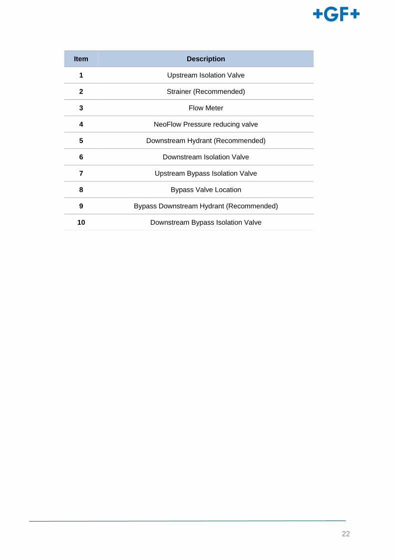
2.2.1 BYPASS LINE
For existing installations with bypass lines, GF Piping Systems recommends the configuration
shown below. Isolation valves 1 and 6 must be securely closed before the valve on the bypass
line is commissioned.
Item Description
1 Upstream Isolation Valve
2 Strainer (Recommended)
3 Flow Meter
4 NeoFlow pressure reducing valve
5 Downstream Hydrant (Recommended)
6 Downstream Isolation Valve
22
Item Description
1 Upstream Isolation Valve
2 Strainer (Recommended)
3 Flow Meter
4 NeoFlow Pressure reducing valve
5 Downstream Hydrant (Recommended)
6 Downstream Isolation Valve
7 Upstream Bypass Isolation Valve
8 Bypass Valve Location
9 Bypass Downstream Hydrant (Recommended)
10 Downstream Bypass Isolation Valve
23
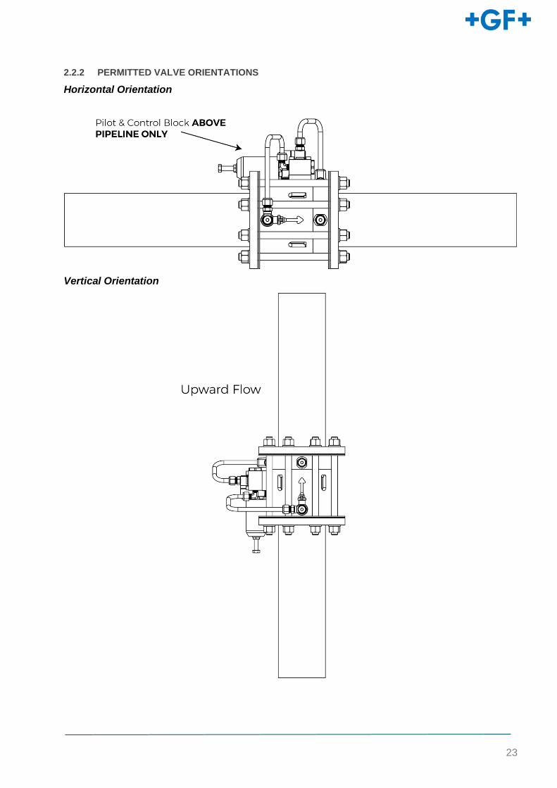
2.2.2 PERMITTED VALVE ORIENTATIONS
Horizontal Orientation
Vertical Orientation
24
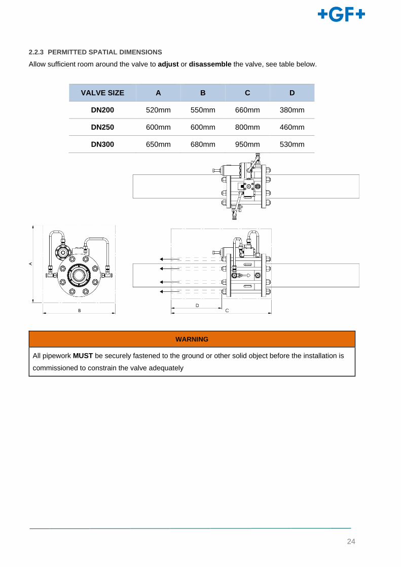
2.2.3 PERMITTED SPATIAL DIMENSIONS
Allow sufficient room around the valve to adjust or disassemble the valve, see table below.
WARNING
All pipework MUST be securely fastened to the ground or other solid object before the installation is
commissioned to constrain the valve adequately
VALVE SIZE A B C D
DN200 520mm 550mm 660mm 380mm
DN250 600mm 600mm 800mm 460mm
DN300 650mm 680mm 950mm 530mm
25
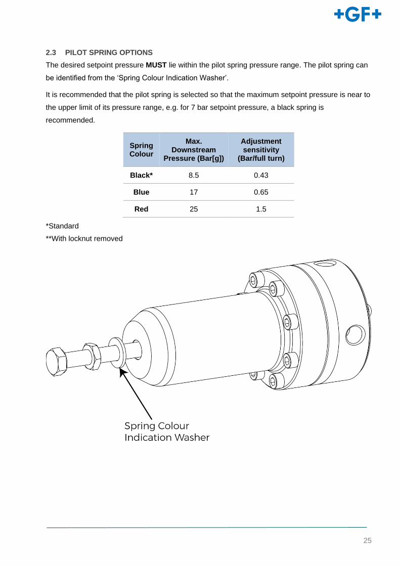
2.3 PILOT SPRING OPTIONS
The desired setpoint pressure MUST lie within the pilot spring pressure range. The pilot spring can
be identified from the ‘Spring Colour Indication Washer’.
It is recommended that the pilot spring is selected so that the maximum setpoint pressure is near to
the upper limit of its pressure range, e.g. for 7 bar setpoint pressure, a black spring is
recommended.
Spring Colour
Max. Downstream
Pressure (Bar[g])
Adjustment sensitivity
(Bar/full turn)
Black* 8.5 0.43
Blue 17 0.65
Red 25 1.5
*Standard
**With locknut removed
26
2.4 VALVE INSTALLATION
CAUTION
Damage to the piping system through the effect of forces! Danger of injury and/or material damage due to
leaks in the piping system.
► Reduce the forces of thermal expansion of the piping system with the use of suitable fixed points
WARNING
Danger of material damage due to excessive pressure! If the NeoFlow pressure reducing valve is put into
operation without a hydrant excessive outlet pressure P2 on the NeoFlow pressure reducing valve (N) can
lead to damage in the piping system.
► Recommendation: use a hydrant .
► When putting into operation without a hydrant: open the outlet shut-off valve only slightly to be able to
control the pressure
WARNING
Leaking flange connection! Danger of injury and/or damage to property due to leaking flange connections.
► Periodic check that no media escapes to the outside.
► If media is exiting at the flanged connectors, they have to be retightened.
► Include the flange and collar width when calculating the Bolt lengths.
► Protect jointing faces and connection parts from damage and poisoning, especially from hard or sharp-
edged particles.
Prior to installation manually press and release the valve cap to ensure it moves freely and returns to
closed
Check nameplate information to verify correct valve has been selected. Ensure the valve is installed
with flow direction arrow in the correct orientation.
27
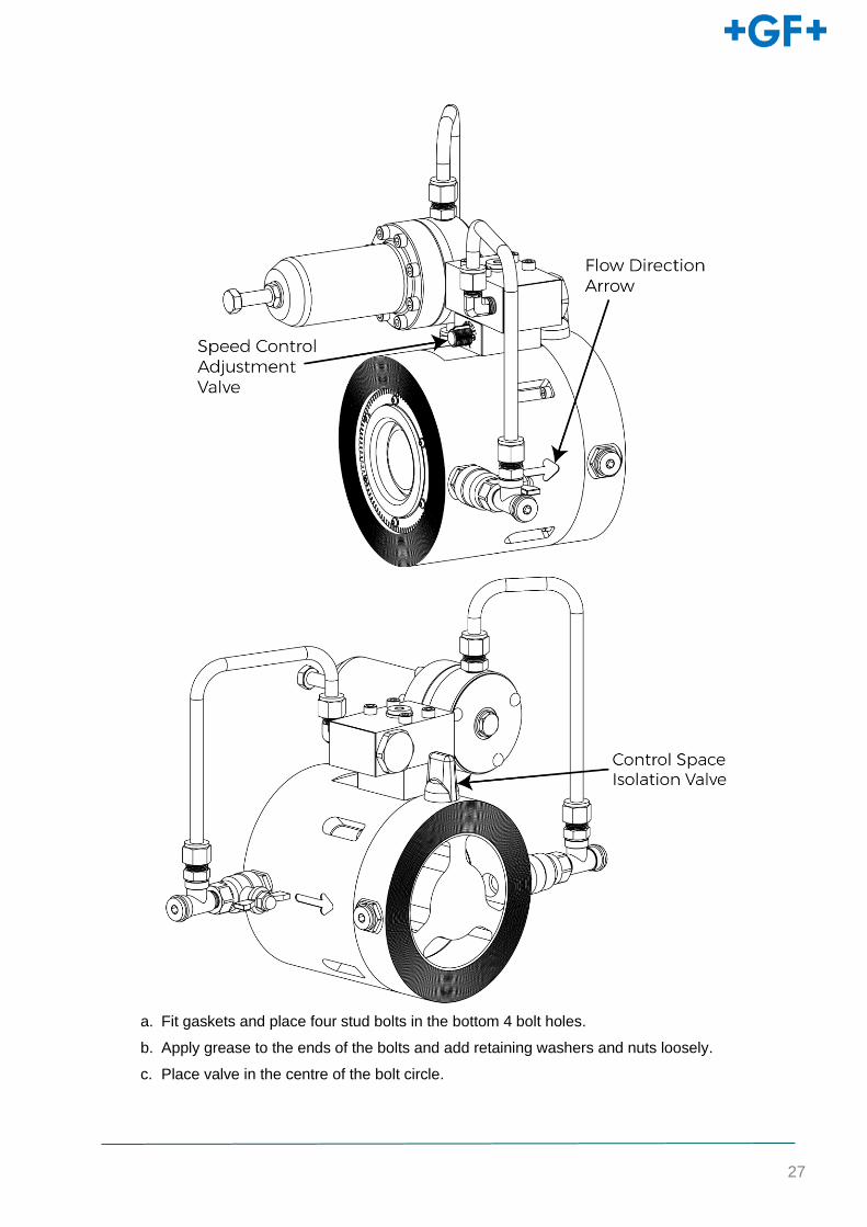
a. Fit gaskets and place four stud bolts in the bottom 4 bolt holes.
b. Apply grease to the ends of the bolts and add retaining washers and nuts loosely.
c. Place valve in the centre of the bolt circle.
28
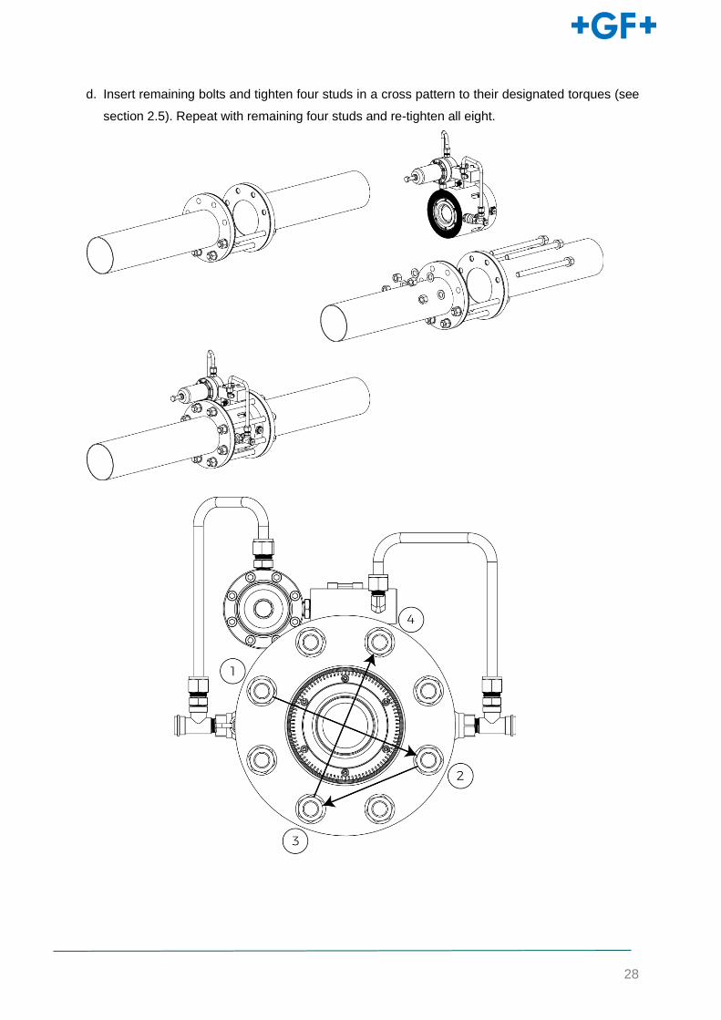
d. Insert remaining bolts and tighten four studs in a cross pattern to their designated torques (see
section 2.5). Repeat with remaining four studs and re-tighten all eight.
29
2.5 VALVE BOLT TORQUES
VALVE SIZE MINIMUM BOLT LENGTH (mm) MAXIMUM TORQUE PER BOLT (Nm)
DN200 420 54
DN250 480 91
DN300 540 104
2.6 FLANGE ADAPTORS
a. Follow steps a-d from section 2.4 within the user specified flange adaptors
b. Place flange adaptor/valve assembly into the pipeline and slide the retaining collars onto the
pipework, ensuring the flow direction is correct.
c. Tighten the retaining collars as per the adaptor manufacturer specifications and proceed with
commissioning.
30
3 COMMISSIONING
IT IS RECOMMENDED THAT ALL STEPS IN THE COMISSIONING PROCESS ARE FOLLOWED
IN SEQUENCE.
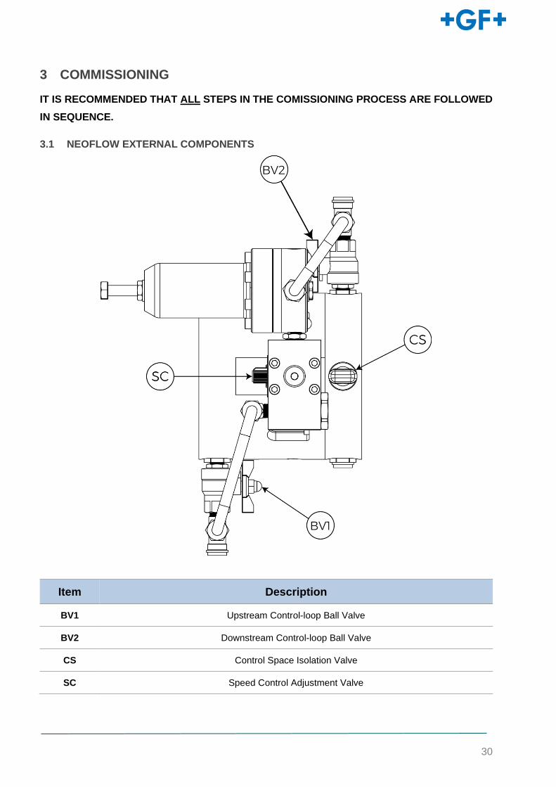
3.1 NEOFLOW EXTERNAL COMPONENTS
Item Description
BV1 Upstream Control-loop Ball Valve
BV2 Downstream Control-loop Ball Valve
CS Control Space Isolation Valve
SC Speed Control Adjustment Valve
31
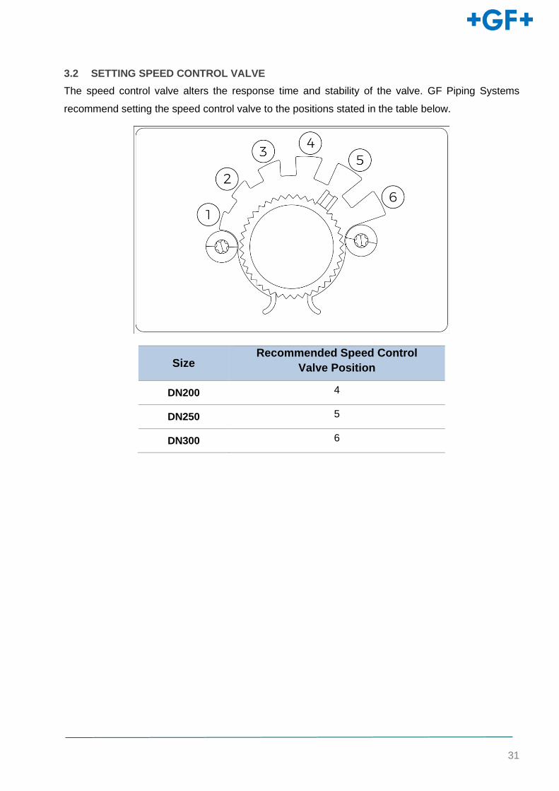
3.2 SETTING SPEED CONTROL VALVE
The speed control valve alters the response time and stability of the valve. GF Piping Systems
recommend setting the speed control valve to the positions stated in the table below.
Size Recommended Speed Control
Valve Position
DN200 4
DN250 5
DN300 6
32
3.3 INITIAL PRESSURISING
CAUTION
Danger of material damage in the pipeline system.
When putting into operation via the main pipeline there is the danger that the initial pressure is too high
and the pipeline system is damaged.
► Putting into operation with an outlet hydrant (H) is recommended.
► To protect the NeoFlow pressure reducing valve (N) from mechanical strain, all components of the
pipeline system must be securely fastened to the ground or another solid object before putting the system
into operation.
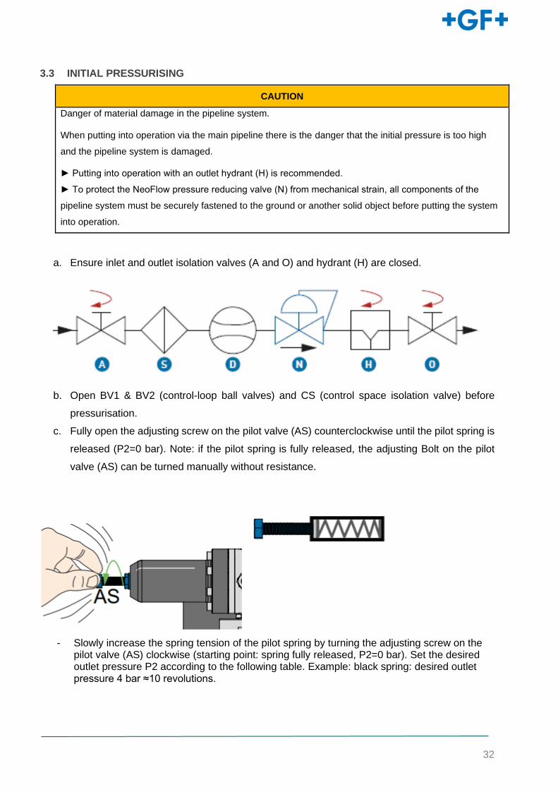
a. Ensure inlet and outlet isolation valves (A and O) and hydrant (H) are closed.
b. Open BV1 & BV2 (control-loop ball valves) and CS (control space isolation valve) before
pressurisation.
c. Fully open the adjusting screw on the pilot valve (AS) counterclockwise until the pilot spring is
released (P2=0 bar). Note: if the pilot spring is fully released, the adjusting Bolt on the pilot
valve (AS) can be turned manually without resistance.
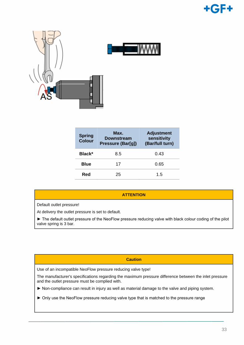
- Slowly increase the spring tension of the pilot spring by turning the adjusting screw on the pilot valve (AS) clockwise (starting point: spring fully released, P2=0 bar). Set the desired outlet pressure P2 according to the following table. Example: black spring: desired outlet pressure 4 bar ≈10 revolutions.
33
Spring Colour
Max. Downstream
Pressure (Bar[g])
Adjustment sensitivity
(Bar/full turn)
Black* 8.5 0.43
Blue 17 0.65
Red 25 1.5
ATTENTION
Default outlet pressure!
At delivery the outlet pressure is set to default.
► The default outlet pressure of the NeoFlow pressure reducing valve with black colour coding of the pilot valve spring is 3 bar.
Caution
Use of an incompatible NeoFlow pressure reducing valve type!
The manufacturer's specifications regarding the maximum pressure difference between the inlet pressure and the outlet pressure must be complied with.
► Non-compliance can result in injury as well as material damage to the valve and piping system.
► Only use the NeoFlow pressure reducing valve type that is matched to the pressure range
34
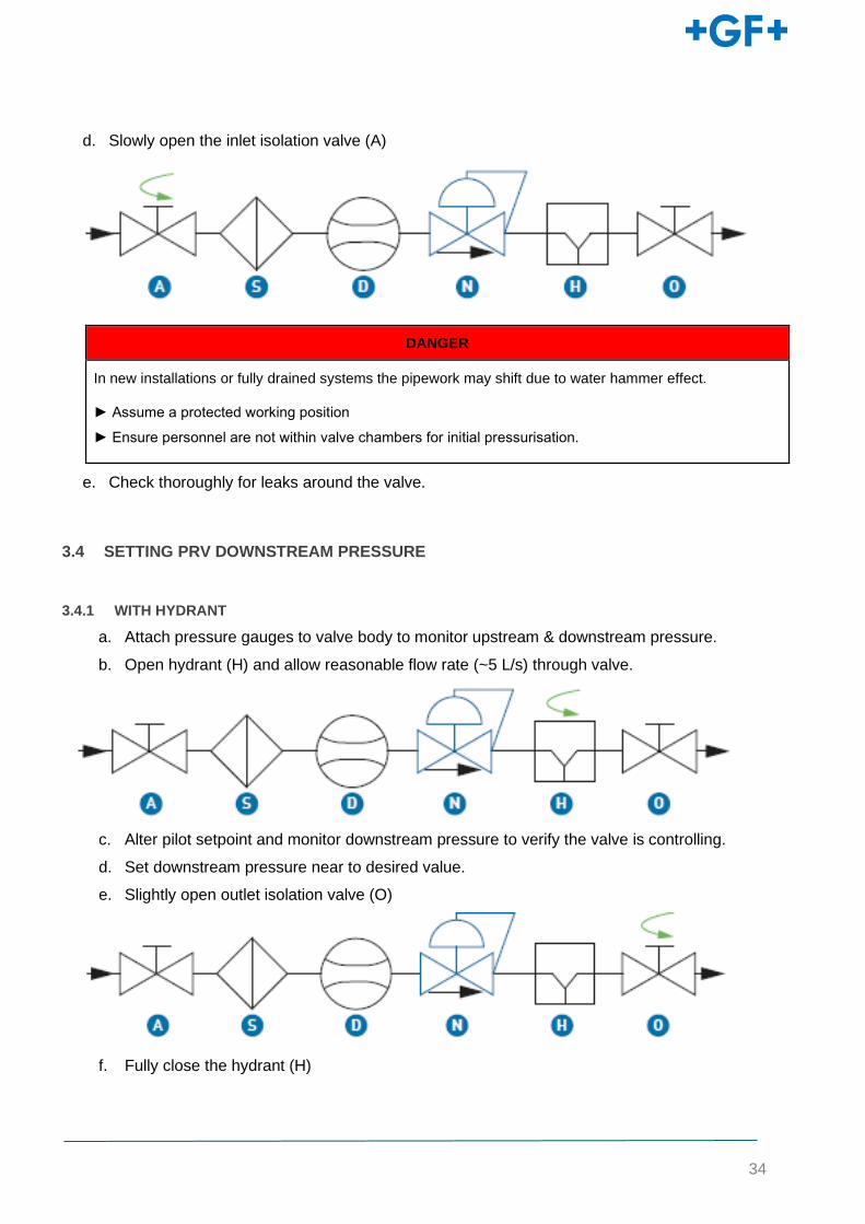
d. Slowly open the inlet isolation valve (A)
DANGER
In new installations or fully drained systems the pipework may shift due to water hammer effect.
► Assume a protected working position
► Ensure personnel are not within valve chambers for initial pressurisation.
e. Check thoroughly for leaks around the valve.
3.4 SETTING PRV DOWNSTREAM PRESSURE
3.4.1 WITH HYDRANT
a. Attach pressure gauges to valve body to monitor upstream & downstream pressure.
b. Open hydrant (H) and allow reasonable flow rate (~5 L/s) through valve.
c. Alter pilot setpoint and monitor downstream pressure to verify the valve is controlling.
d. Set downstream pressure near to desired value.
e. Slightly open outlet isolation valve (O)
f. Fully close the hydrant (H)

35
g. Fully open the outlet isolation valve (O).
h. Fine tune pilot setpoint to desired downstream pressure, then tighten and secure with the
nut.

36
CAUTION
Danger of displacement of the adjusting Bolt on the pilot valve (AS) during tightening of the locking nut!
Potential unintended change of the nominal pressure.
► Always fix the the adjusting screw on the pilot valve (AS) during tightening of the locking nut.
► Check the nominal pressure of pressure gauge KH5 after tightening the locking nut.
3.5 ADJUSTING THE SPEED CONTROL
Turning the Speed Control Valve clockwise will increase valve response time. Turning the
Speed Control Valve anti-clockwise will improve valve stability. Only if instability is observed
should the Speed Control Valve be set to a value other than in the table.
a. It is recommended the speed control valve is adjusted after valve has run for at least 10
minutes. This allows air in the system to purge.
b. If instability occurs, move the valve one notch anticlockwise to a lower setting and wait 1
minute.
c. Repeat step b if instability is still present.
37
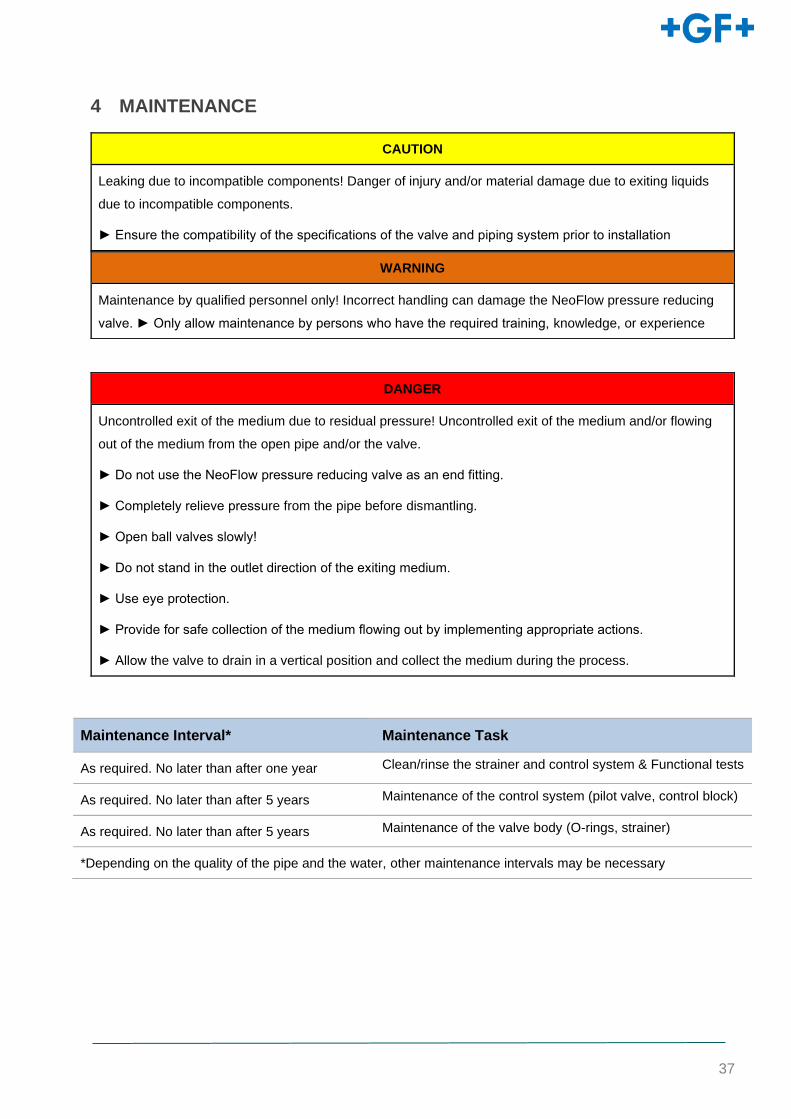
4 MAINTENANCE
CAUTION
Leaking due to incompatible components! Danger of injury and/or material damage due to exiting liquids
due to incompatible components.
► Ensure the compatibility of the specifications of the valve and piping system prior to installation
DANGER
Uncontrolled exit of the medium due to residual pressure! Uncontrolled exit of the medium and/or flowing
out of the medium from the open pipe and/or the valve.
► Do not use the NeoFlow pressure reducing valve as an end fitting.
► Completely relieve pressure from the pipe before dismantling.
► Open ball valves slowly!
► Do not stand in the outlet direction of the exiting medium.
► Use eye protection.
► Provide for safe collection of the medium flowing out by implementing appropriate actions.
► Allow the valve to drain in a vertical position and collect the medium during the process.
Maintenance Interval* Maintenance Task
As required. No later than after one year Clean/rinse the strainer and control system & Functional tests
As required. No later than after 5 years Maintenance of the control system (pilot valve, control block)
As required. No later than after 5 years Maintenance of the valve body (O-rings, strainer)
*Depending on the quality of the pipe and the water, other maintenance intervals may be necessary
WARNING
Maintenance by qualified personnel only! Incorrect handling can damage the NeoFlow pressure reducing
valve. ► Only allow maintenance by persons who have the required training, knowledge, or experience
38
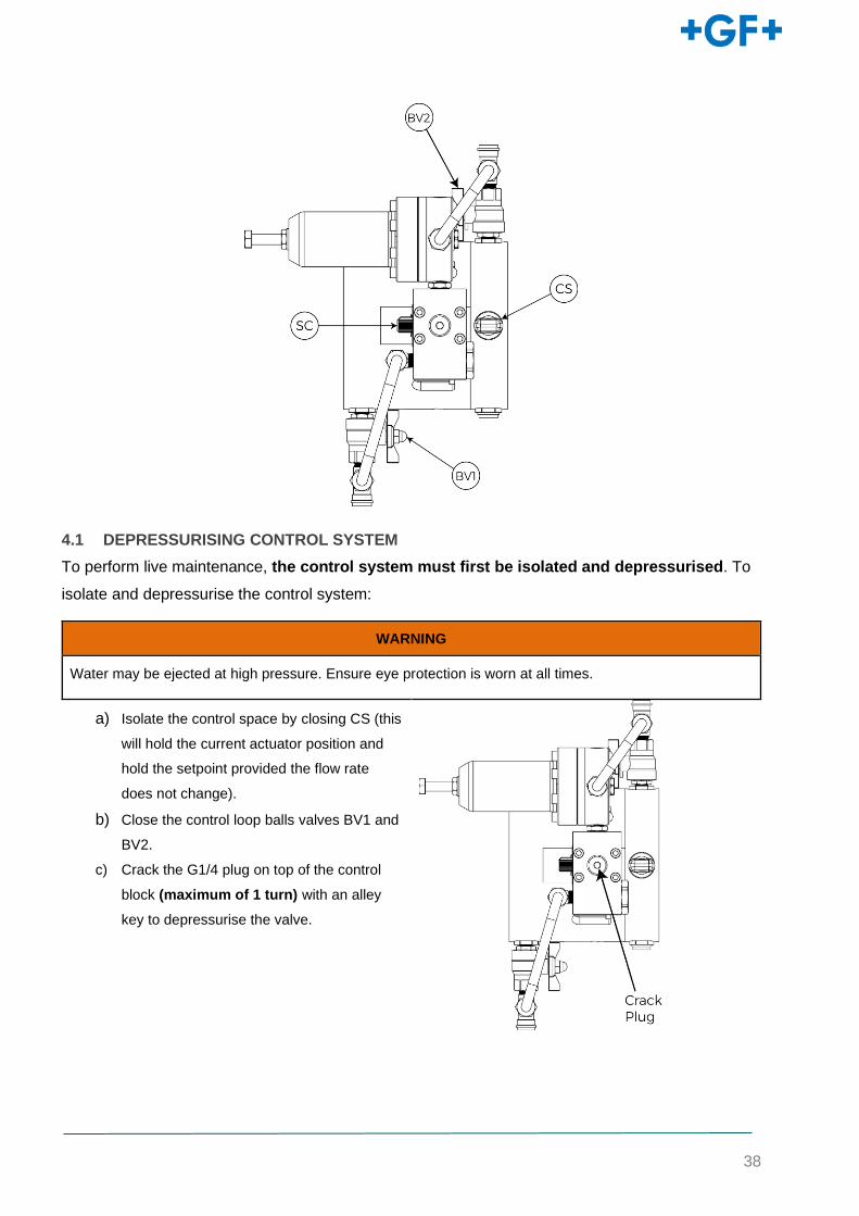
4.1 DEPRESSURISING CONTROL SYSTEM
To perform live maintenance, the control system must first be isolated and depressurised. To
isolate and depressurise the control system:
WARNING
Water may be ejected at high pressure. Ensure eye protection is worn at all times.
a) Isolate the control space by closing CS (this
will hold the current actuator position and
hold the setpoint provided the flow rate
does not change).
b) Close the control loop balls valves BV1 and
BV2.
c) Crack the G1/4 plug on top of the control
block (maximum of 1 turn) with an alley
key to depressurise the valve.
39
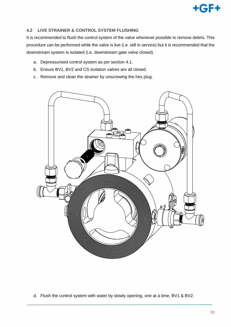
4.2 LIVE STRAINER & CONTROL SYSTEM FLUSHING
It is recommended to flush the control system of the valve whenever possible to remove debris. This
procedure can be performed while the valve is live (i.e. still in service) but it is recommended that the
downstream system is isolated (i.e. downstream gate valve closed).
a. Depressurised control system as per section 4.1.
b. Ensure BV1, BV2 and CS isolation valves are all closed.
c. Remove and clean the strainer by unscrewing the hex plug.
d. Flush the control system with water by slowly opening, one at a time, BV1 & BV2.
40
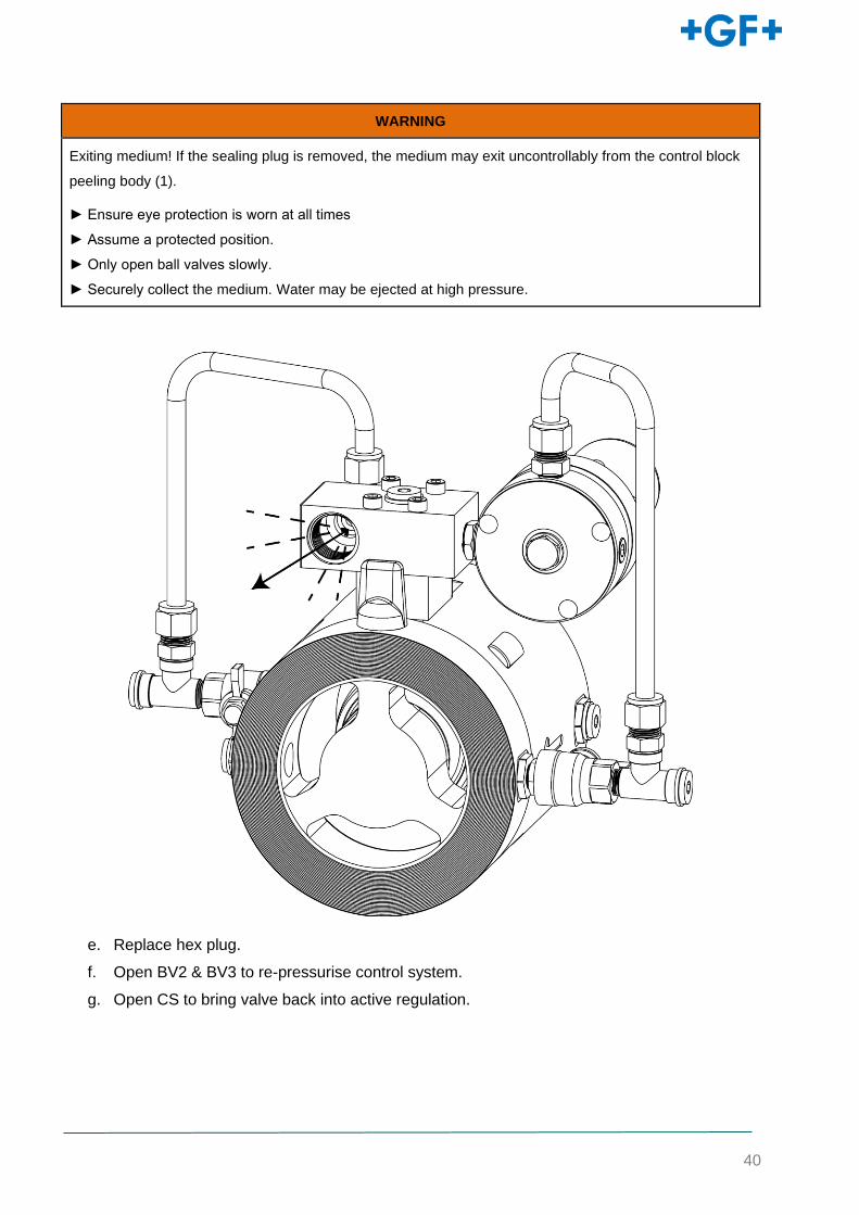
WARNING
Exiting medium! If the sealing plug is removed, the medium may exit uncontrollably from the control block
peeling body (1).
► Ensure eye protection is worn at all times
► Assume a protected position.
► Only open ball valves slowly.
► Securely collect the medium. Water may be ejected at high pressure.
e. Replace hex plug.
f. Open BV2 & BV3 to re-pressurise control system.
g. Open CS to bring valve back into active regulation.
41
4.3 VALVE REMOVAL
DANGER
Exiting medium! Ensure suitable isolations are in place upstream and downstream of the NeoFlow
installation to prevent release of pressure or continued flow of water.
► Ensure eye protection is worn at all times
► Use safe bolting practices. Undo lower bolts first to relieve any residual pressure and do not remove
until satisfied the line is depressurised and drained.
► Assume a protected position
► Securely collect the medium
a. Loosen and remove all flange bolts from around the valve in the pipe.
b. When all bolts have been removed, apply outward pressure on the mating flanges to release
the NeoFlow valve.
WARNING
Exiting medium! If KH4 is open, the medium exits uncontrollably from the ball valve. This may lead to injury
or material damage.
► Assume a protected position.
► Only open ball valves slowly.

42
.
43
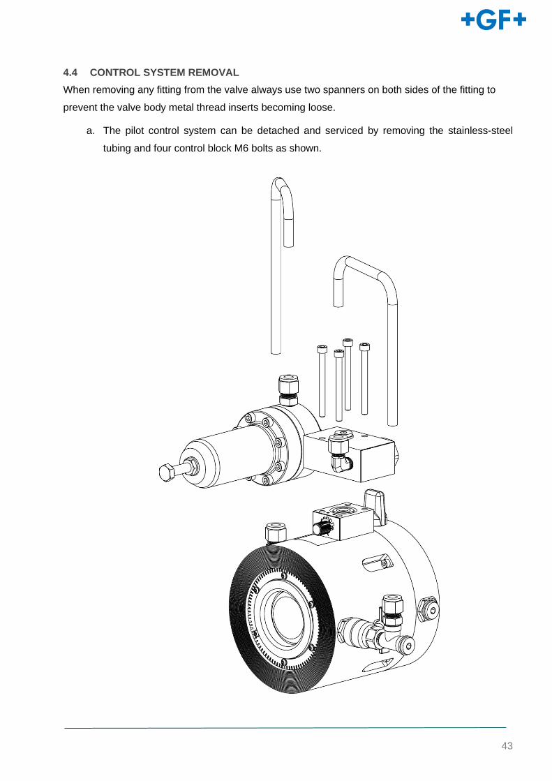
4.4 CONTROL SYSTEM REMOVAL
When removing any fitting from the valve always use two spanners on both sides of the fitting to
prevent the valve body metal thread inserts becoming loose.
a. The pilot control system can be detached and serviced by removing the stainless-steel
tubing and four control block M6 bolts as shown.
44
4.5 CONTROL SYSTEM SERVICING
4.5.1 CONTROL BLOCK
See Section 1.9 for Bill of Materials.
a. Remove Strainer with an alley key and flush through with water in accordance with section
4.2.
b. Remove the restrictor insert with a flat head screwdriver and inspect for any blockages.
c. On reassembly, it is recommended that the O-ring seals are lightly lubricated using a WRAS
approved grease.
45
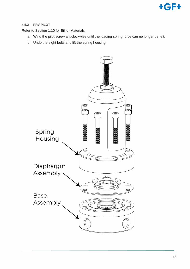
4.5.2 PRV PILOT
Refer to Section 1.10 for Bill of Materials.
a. Wind the pilot screw anticlockwise until the loading spring force can no longer be felt.
b. Undo the eight bolts and lift the spring housing.
46
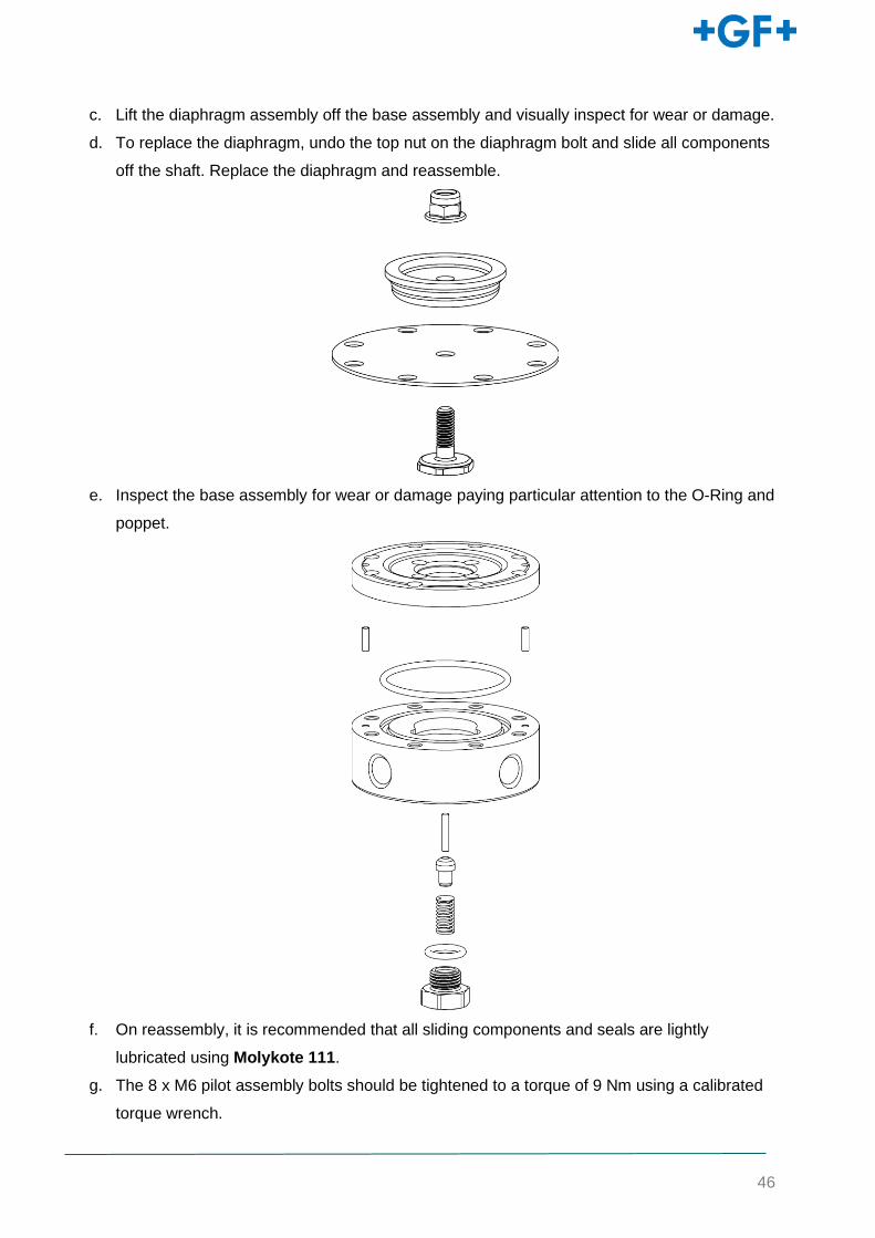
c. Lift the diaphragm assembly off the base assembly and visually inspect for wear or damage.
d. To replace the diaphragm, undo the top nut on the diaphragm bolt and slide all components
off the shaft. Replace the diaphragm and reassemble.
e. Inspect the base assembly for wear or damage paying particular attention to the O-Ring and
poppet.
f. On reassembly, it is recommended that all sliding components and seals are lightly
lubricated using Molykote 111.
g. The 8 x M6 pilot assembly bolts should be tightened to a torque of 9 Nm using a calibrated
torque wrench.
47
4.6 MAIN BODY
See Section 1.8 for Bill of Materials.
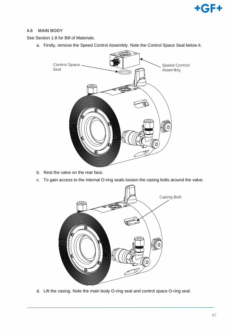
a. Firstly, remove the Speed Control Assembly. Note the Control Space Seal below it.
b. Rest the valve on the rear face.
c. To gain access to the internal O-ring seals loosen the casing bolts around the valve.
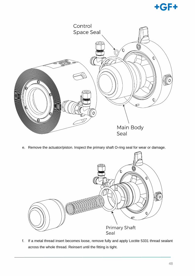
d. Lift the casing. Note the main body O-ring seal and control space O-ring seal.
48
e. Remove the actuator/piston. Inspect the primary shaft O-ring seal for wear or damage.
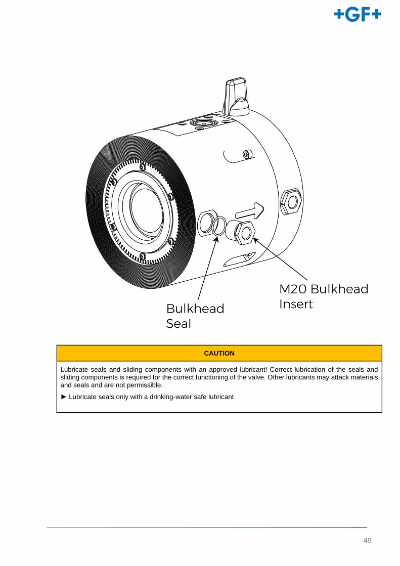
f. If a metal thread insert becomes loose, remove fully and apply Loctite 5331 thread sealant
across the whole thread. Reinsert until the fitting is tight.
49
CAUTION
Lubricate seals and sliding components with an approved lubricant! Correct lubrication of the seals and sliding components is required for the correct functioning of the valve. Other lubricants may attack materials and seals and are not permissible.
► Lubricate seals only with a drinking-water safe lubricant

50
4.6.1 SHUT-OFF SEAL SERVICING
If the shut-off seal needs servicing, it can be accessed by removing the inlet screws. This can be
performed with the control system still on the valve.
a. Remove the inlet screws using a Torx-Plus screwdriver head. Remove the inlet strainer
and inlet piece to reveal the shut off seal.
b. Remove the shut off seal and inspect for any cracks or signs of wear.
c. Before replacing the seal check both the face on the casing and inlet for any debris.
51
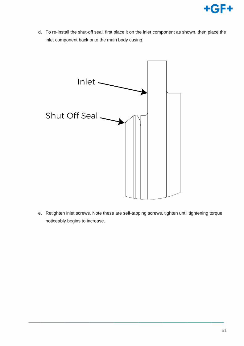
d. To re-install the shut-off seal, first place it on the inlet component as shown, then place the
inlet component back onto the main body casing.
e. Retighten inlet screws. Note these are self-tapping screws, tighten until tightening torque
noticeably begins to increase.
52
5 TROUBLESHOOTING
5.1 DIAGNOSTICS
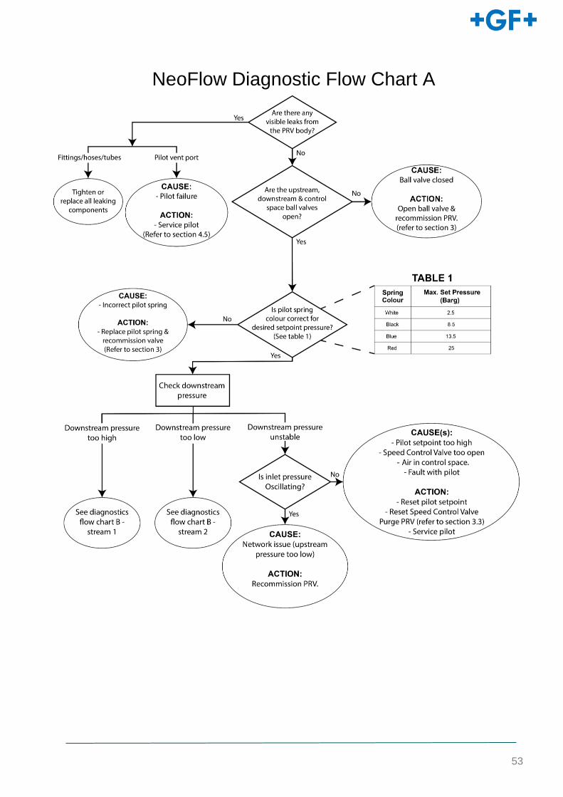
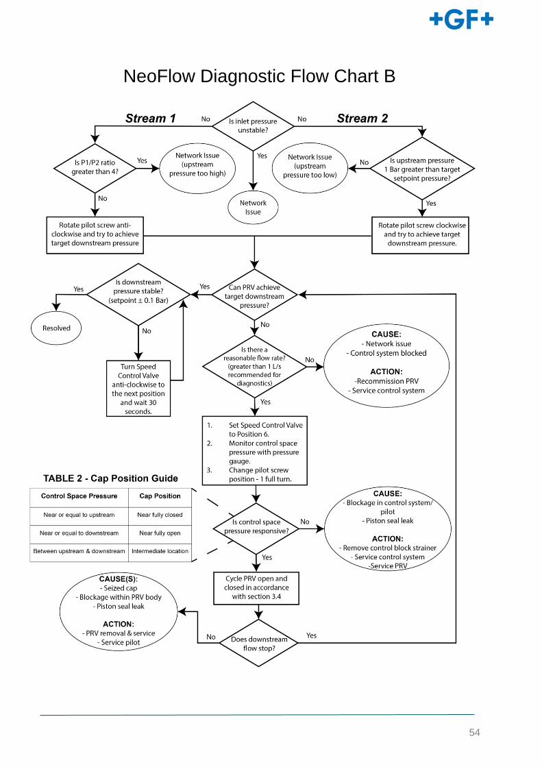
If the valve is not working as intended, follow NeoFlow Diagnostics Flow Chart A. If the diagnostics
flow charts cannot find the root cause or resolve the issue, full valve removal and service is
necessary. Contact GF Piping Systems sales team if required.
53
NeoFlow Diagnostic Flow Chart A
54
NeoFlow Diagnostic Flow Chart B


![be caused by malfunction Of hydraulic parts, LCRV [Load Conscious Regulating Valve]/PRCV [Pressure Conscious Regulating Valve} problems, soft use of braking system and low car mileage](https://img.pdfslide.us/doc/110x75/5e3e8098850ef5701744993c/be-caused-by-malfunction-of-hydraulic-parts-lcrv-load-conscious-regulating-valveprcv.jpg)