Embed Size (px)
Citation preview
- 1 -
Instruction Manual
Model GA-52CxMagnetic Locator
Manufactured BySchonstedt Instrument Company
100 Edmond RoadKearneysville, WV 25430
(304) 725-1050Fax (304) 725-1095
Made in USA
Preface The Model GA-52Cx Magnetic Locator is a product of over forty-five years of experience in producing theworld’s finest flux-gate magnetometers and magnetic detectors for aerospace, military and civilianapplications. The GA-52Cx incorporates the knowledge obtained from manufacturing under the most rigidquality control standards. The heart of the GA-52Cx is its patented Schonstedt HeliFlux magnetic fieldsensors. These sensors, acknowledged to be the world’s finest, make possible the unequaled performanceof our locators.
June 2003

- 2 -
Table of Contents
Operation PageIntroduction 3Turn-On, Volume and Sensitivity Settings 3Search Procedure 4
Application NotesBasic Signal Patterns 5Strongly Magnetized Markers 6Locating Manholes, Septic Tanks and Well Casings 7Locating Objects under Snow or Water and Tracing Barbed Wire 8Searching Areas Along a Chain Link Fence 9Locating Valve Boxes 10Locating Cast-Iron Pipes 10Locating Steel Drums 11Additional Applications 11Other Notes 11
MaintenanceReplacement of Batteries 12Troubleshooting Guide 13
Service Information 13
Specifications 13
Warranty and Shipping Information 14
Important Notice
Schonstedt believes the statements contained herein to be accurate and reliable. But their accuracy,reliability, or completeness is not guaranteed.
Schonstedt’s only obligation shall be to repair or replace any instrument proved to be defective withinseven years of purchase. Schonstedt shall not be responsible for any injury to persons or property, direct orconsequential, arising from the use of any instrument.

- 3 -
Operation
Introduction
The GA-52Cx Magnetic Locator detects the magnetic field of a ferromagnetic object. It responds to thedifference in the magnetic field between two sensors spaced about 20 inches apart. The response is achange in the frequency of the signal emitted by the piezoelectric speaker.
Figure 1 illustrates an application of the locator in which it is used to detect an iron marker of the type usedfor property line identification. As shown, the magnetic field of the iron marker is stronger at sensor Athan it is at sensor B. As a result, the frequency from the piezo electric speaker is higher than the idlingfrequency, 40 Hz, which exists when the field strength is the same at both sensors.
Figure 1. Detecting Magnetic Field of an Iron Marker
Turn-On, Sensitivity and Volume Settings
Set the On-Off/Sensitivity Control to position 2 and adjust the Volume control until the idling tone reachesa desired level. Setting the Sensitivity control to position 2 provides what is referred to as the “NormalOperating Range.” Positions 3 to 5 increase the sensitivity; position 1 decreases the sensitivity.
The locator can be oriented in any direction without producing a significant change in the frequency of thetone from its idling frequency.
When using headphones the Volume Control has no affect on the output level of the audio signal.
Figure 2. Sensitivity Set for Normal Range (position 2)

- 4 -
Search Procedure
Set the sensitivity control to position 2 (Normal Range) and grasp the locator as illustrated. Because theupper sensor is located near where the locator is usually held, wristwatches may produce unwanted changes in the tones frequency.(Remove your wrist watch or hold the locator in the other hand).Keep the locator away from your shoes, since they might containmagnetic material.
To obtain maximum area coverage, the locator should be swept fromside-to-side. When the locator comes within range of an object, youwill hear an increase in the frequency of the output signal.
Figure 3. Searching with the locator

- 5 -
Application Notes
Basic Signal Patterns
Figure 4. Signals from Vertical and Horizontal Targets
After you have detected the presence of a target, hold the locator vertically and move it back and forth in an“X” pattern. The peak signal occurs directly over a vertical target, and over the ends of a horizontal target.
The “X” pattern is ideal for pinpointing small objects. A 1-1/4-inch PK nail buried up to 12 inches can belocated so precisely with this technique that it can be uncovered using a 1/2-inch star drill.
Figure 5. “X” Pattern Provides Precision Locating
If you find more than one signal in the vicinity of a target, just raise the locator several inches higher orreduce the sensitivity setting. Any signal that disappears when the locator is raised or the sensitivity isreduced is probably not coming from the actual target. The signal from a rusty bolt or other small item willdecrease much faster with distance than the signal from a larger target such as a corner marker. An 18-inchlength of 3/4-inch pipe can be located at depths up to 9 feet.
Figure 6. Raising the Locator Eliminates Unwanted Signals

- 6 -
Strongly Magnetized Markers
A strongly magnetized marker at or near the surface may provide location information that is misleading.
The heavy line in Figure 7 represents the variations in tone frequencies when the locator is moved over themarker. When moving the instrument from A to B, the frequency of the tone increases and then suddenlydecreases at B. From just beyond B the frequency of the tone increases sharply, becomes very high directlyover the marker and decrease just before reaching C. From C to D the pattern is the reverse of that from Ato B. It is obvious that the locator must enter the B-C region. Otherwise the marker might be assumed to bebetween A and B, or C and D.
Figure 7. Signal Pattern From a Strongly Magnetized Marker
This phenomenon is explained by the fact that the locator is sensitive to the magnetic field componentsparallel to its long axis. At points B and C the field is perpendicular to the locator so no high frequency isproduced at these points.

- 7 -
Locating Manholes, Septic Tanks and Well Casings
The magnetic field is strongest at the edge of a shallow manhole cover. You can easily trace the edges ofcovers near the surface. Locating depth ranges up to 10 feet.
The great length of a well casing provides a strong field at the surface that makes it easy to locate casingsburied up to 18 feet deep.
Figure 8. Locating Manhole Covers Figure 9. Locating Water Well Casings
The GA-52Cx can be used to precisely locate the metal handles or reinforcing bars on septic tank covers atdepths of up to 4 feet.
Figure 10. Signal Pattern Provided by Septic Tank Covers

- 8 -
Locating Objects under Snow or Water and Tracing Barbed Wire
The locator can be used in flooded areas, just keep the electronic unit out of the water.
Snow poses no problem. Thrust the locator into the snow as deep as necessary to locate the target.
Figure 11. Locating Objects Under Snow or Water
You can often trace barbed wire (from old fence lines) buried just beneath the surface. Even if the wire isonly a trail of rust it can still be detected near the surface. Tip the locator a little lower than usual, but notparallel with the ground.
First, examine trees for bench marks and bits of embedded barbed wire. Then hold the locator parallel withthe direction of the wire.
Figure 12. Tracing Barbed Wire from Old Fence Lines

- 9 -
Searching Areas Along a Chain Link Fence
Searching in the vicinity of a chain link fence requires a reduced sensitivity setting and also some controlover the orientation of the locator. As illustrated in Figure 13, position the locator horizontally, with itslong axis perpendicular to the fence. This ensures that the upper sensor is kept away from the fence.
Figure 13. Searching in the Vicinity of a Chain Link Fence
Perform the search by slowly moving the locator forward along the fence while also moving it in to theright and to the left. This technique allows you to search an area several feet wide as you move forward.Listen for an abrupt drop in the signal, (as shown by the null in Figure 14.) that will occur when thelower sensor, located 1-5/8 inches from the end of the locator, is directly over the stake. Any variationin the position of the locator will produce an abrupt rise in the frequency of the signal.
Figure 14. Placement of Locator While Searching Along a Chain Link Fence
- 10 -
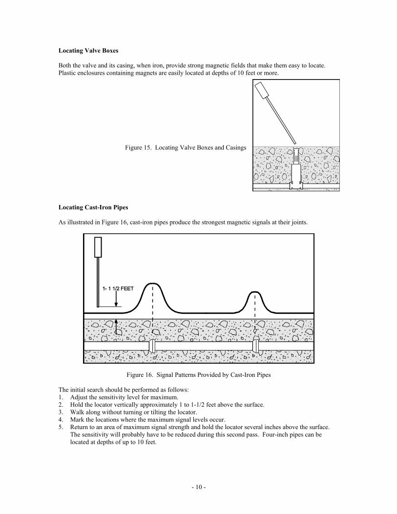
Locating Valve Boxes
Both the valve and its casing, when iron, provide strong magnetic fields that make them easy to locate.Plastic enclosures containing magnets are easily located at depths of 10 feet or more.
Figure 15. Locating Valve Boxes and Casings
Locating Cast-Iron Pipes
As illustrated in Figure 16, cast-iron pipes produce the strongest magnetic signals at their joints.
Figure 16. Signal Patterns Provided by Cast-Iron Pipes
The initial search should be performed as follows:1. Adjust the sensitivity level for maximum.2. Hold the locator vertically approximately 1 to 1-1/2 feet above the surface.3. Walk along without turning or tilting the locator.4. Mark the locations where the maximum signal levels occur.5. Return to an area of maximum signal strength and hold the locator several inches above the surface.
The sensitivity will probably have to be reduced during this second pass. Four-inch pipes can belocated at depths of up to 10 feet.

- 11 -
Locating Steel Drums
As shown in Figure 17, the GA-52Cx’s signal pattern will vary depending on the vertical or horizontalorientation of the drum and also how deep it is buried. A fifty-five gallon drum can be located at depths ofup to 10 feet.
Figure 17. Signal Patterns Provided by Steel Drums
Additional Applications
1. The military and many local and state police departments use the GA-52Cx to detect buriedordnance and discarded weapons.
2. People drilling in an area where hazardous materials might be encountered use the GA-52Cx tosearch the area prior to drilling. Other Schonstedt magnetometers are available that can belowered down the hole for periodic checks as drilling progresses.
Other Notes
1. A burbling sound indicates the presence of an energized power line.
2. The instrument will not detect non-magnetic materials such as gold, silver,copper, brass and aluminum.
- 12 -
Maintenance
The GA-52Cx is designed and built to give trouble-free operation. Normally, maintenance is limited to theoccasional replacement of batteries. In the event that a malfunction does occur, refer to the trouble-shooting guide on page 11. It lists a few problems that can generally be corrected in the field so that youwill be able to continue using the locator without interruption.
Replacement of Batteries
The GA-52Cx is powered by two alkaline 9-Volt batteries. Alkaline or lithium batteries may be used,however lithium batteries are recommended for their exceptional performance. The battery manufacturersadvertise a 10 year shelf life, two to four times the operational life of an alkaline battery, as well as beingenvironmentally safe. If battery leakage does occur, lithium batteries do not cause severe damage to theunit as would alkaline batteries.
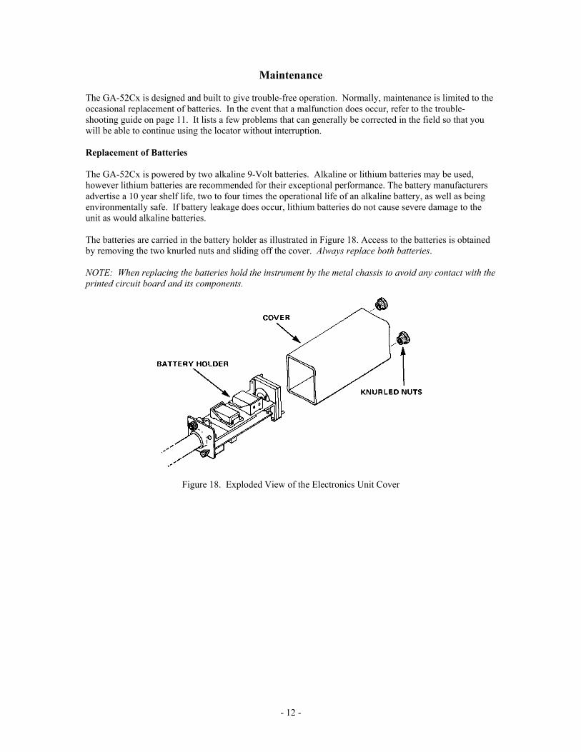
The batteries are carried in the battery holder as illustrated in Figure 18. Access to the batteries is obtainedby removing the two knurled nuts and sliding off the cover. Always replace both batteries.
NOTE: When replacing the batteries hold the instrument by the metal chassis to avoid any contact with theprinted circuit board and its components.
Figure 18. Exploded View of the Electronics Unit Cover

- 13 -
Troubleshooting Guide
Symptoms Possible Cause How to Check How to FixDead Dead Batteries
Batteries not makingcontact
Battery leakage
Replace
Check for contactcorrosion
Do not remove*
--------
Clean contacts
Return unit to factory
Intermittent Batteries not makinggood contact
Check for corrosion Clean contacts
Uncontrollablescreaming
Weak batteries Replace --------
* Most battery manufacturers’ warranties cover the cost of repair or replacement of any device damagedby their batteries. Removing batteries that leak will void their warranty.
SERVICE INFORMATION
If your locator needs service, please return it to the factory (in its case) along with the followinginformation: Name, Address, Telephone and Fax Numbers, Where Purchased, Date of Purchase, andDescription of Problem(s). A tele-faxed estimate will be provided prior to service work being done. Seeshipping information.
SPECIFICATIONS(Specifications subject to change without notice.)
Input PowerBattery LifeOutput
WeightOperating TemperatureOverall LengthWaterproof LengthNominal Sensor SpacingConstruction
Supplied by two alkaline 9-V batteries40 hours (Intermittent usage)Approximately 40 Hz idle tone in speaker. Tone frequency increases(or decreases) with gradient-field intensity.Approximately 2.5 lb. (1.13 kg)-13 F to 140 F (-25 C to 60 C)42-5/16 in (107.4cm)34-1/2 in. (87.6 cm)20 in. (50.8 cm)Rugged, modular all solid state

- 14 -
LIMITED WARRANTY
The Schonstedt Instrument Company (Schonstedt) warrants each product of its manufacture to be free fromdefects in material and workmanship subject to the following terms and conditions. The warranty iseffective for 7 years (with the return of the Customer Registration Card) after the shipment by Schonstedtto the original purchaser.
Schonstedt’s obligation under the warranty is limited to servicing or adjusting any product returned to thefactory for this purpose and to replacing any defective part thereof. Such product must be returned by theoriginal purchaser, transportation charges prepaid, with proof in writing, to our satisfaction, of the defect.If the fault has been caused by misuse or abnormal conditions of operation, repairs will be billed at cost.Prior to repair, in this instance, a cost estimate will be submitted. Service or shipping information will befurnished upon notification of the difficulty encountered. Model and serial numbers must be supplied byuser. Batteries are specifically excluded under the warranty.
Schonstedt shall not be liable for any injury to persons or property or for any other special or consequentialdamages sustained or expenses incurred by reason of the use of any Schonstedt product.
FOR SERVICE OR REPAIRPlease ship locator (in its case) to:
Schonstedt Instrument Company100 Edmond Road
Kearneysville, WV 25430
PATENTS
Manufactured under one or more of the following Patents: United States: 4,163,877; 4,258,320;4,803,773; 4,839,624; 5,097,211; 5,136,245; 5,138,761; 5,239,290. Other United States and foreignpatents pending.