Embed Size (px)
Citation preview
Micro MotionTM
Micro Motion®
CMF400 SensorInstallation Instructions
Quick Reference GuideP/N 3006075, Rev. DMay 2003
For online technical support, use the EXPERT2™ system at www.expert2.com. To speak to a customer service representative, call the support center nearest you:• In the U.S.A., phone 1-800-522-MASS
(1-800-522-6277)• In Canada and Latin America, phone
(303) 530-8400• In Asia, phone (65) 6770-8155• In the U.K., phone 0800 - 966 180 (toll-free)• Outside the U.K., phone +31 (0) 318 495 670

BEFORE YOU BEGIN
This quick reference guide explains basic installation guidelines for the Micro Motion® ELITE® CMF400 sensor. For more information, refer to the instruction manual that was shipped with the sensor.
European installationsThis Micro Motion product complies with all applicable European directives when properly installed in accordance with the instructions in this quick reference guide. Refer to the EC declaration of conformity for directives that apply to this product.
The EC declaration of conformity, with all applicable European directives, and the complete ATEX Installation Drawings and Instructions are available on the internet at www.micromotion.com/atex or through your local Micro Motion support center.
INTRODUCTION
The sensor makes up one part of a Coriolis flowmeter. The other part is a transmitter.
Installation optionsThe CMF400 sensor is available with:
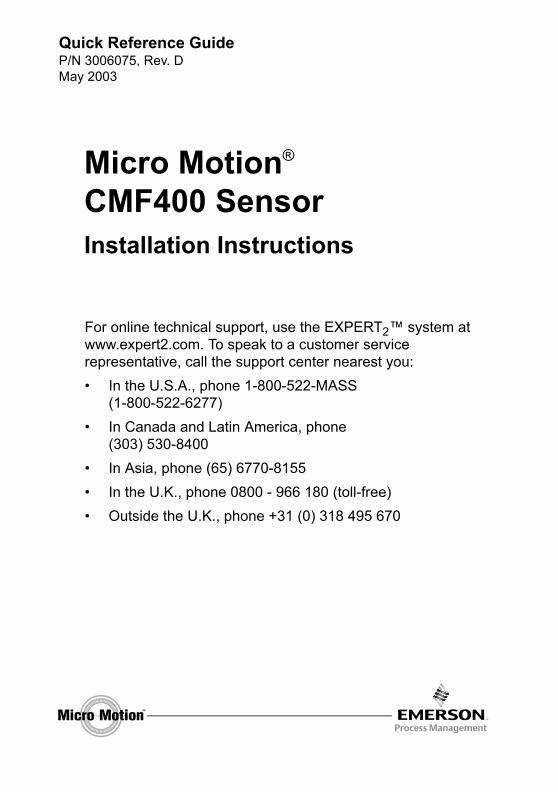
• An integral core processor for connecting to a 4-wire remotely mounted transmitter or to a user-supplied remote host (see Figure 1 or Figure 2).
• A 9-wire junction box for connecting to a remotely mounted transmitter, or to a remotely mounted core processor (see Figure 3 or Figure 4).
1
©2003, Micro Motion, Inc. All rights reserved. Micro Motion is a registered trademark of Micro Motion, Inc. The Micro Motion and Emerson logos are trademarks of Emerson Electric Co. All other trademarks are property of their respective owners.
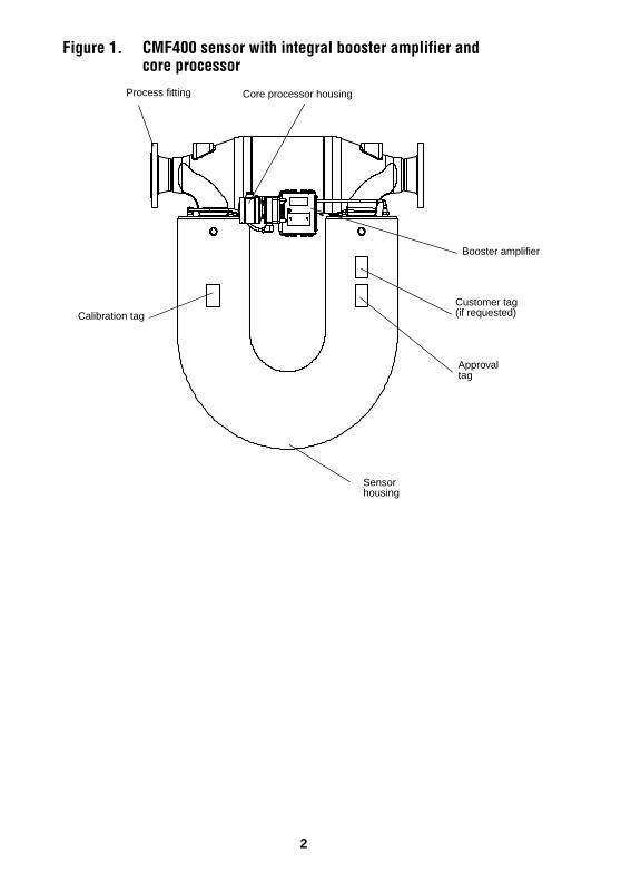
Figure 1. CMF400 sensor with integral booster amplifier andcore processor
Calibration tag
Process fitting
Booster amplifier
Approval tag
Sensor housing
Core processor housing
Customer tag (if requested)
2
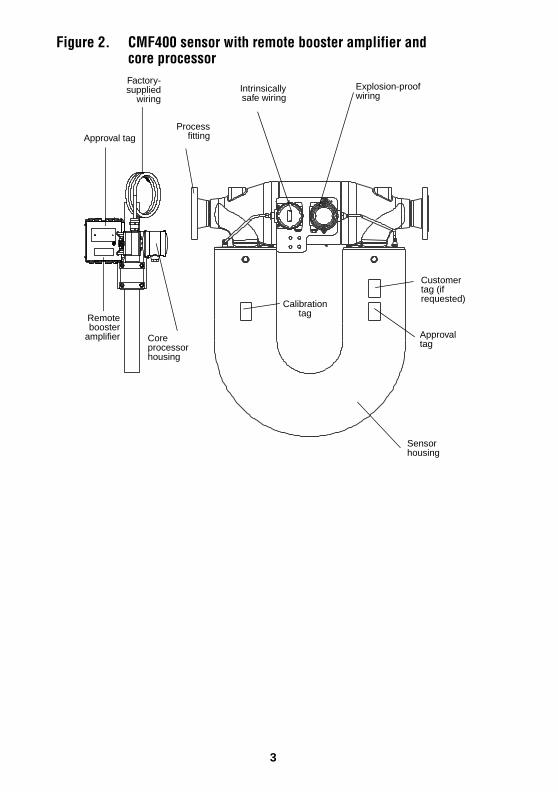
Figure 2. CMF400 sensor with remote booster amplifier andcore processor
Core processor housing
Processfitting
Intrinsicallysafe wiring
Explosion-proof wiring
Sensor housing
Approval tag
Approval tag
Factory-supplied
wiring
Calibrationtag
Customer tag (if requested)
Remotebooster
amplifier
3
Figure 3. CMF400 sensor with integral booster amplifier andjunction box
Processfitting
Calibrationtag
Sensor housing
Junction box
Approval tag
Customer tag(if requested)
Boosteramplifier
4
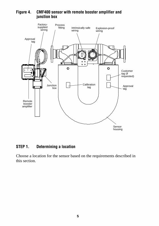
Figure 4. CMF400 sensor with remote booster amplifier andjunction box
STEP 1. Determining a location
Choose a location for the sensor based on the requirements described in this section.
Approvaltag
Processfitting Explosion-proof
wiring
Junctionbox
Approval tag
Sensor housing
Intrinsically safe wiring
Remotebooster
amplifier
Factory-supplied
wiring
Customer tag (if requested)
Calibration tag
5
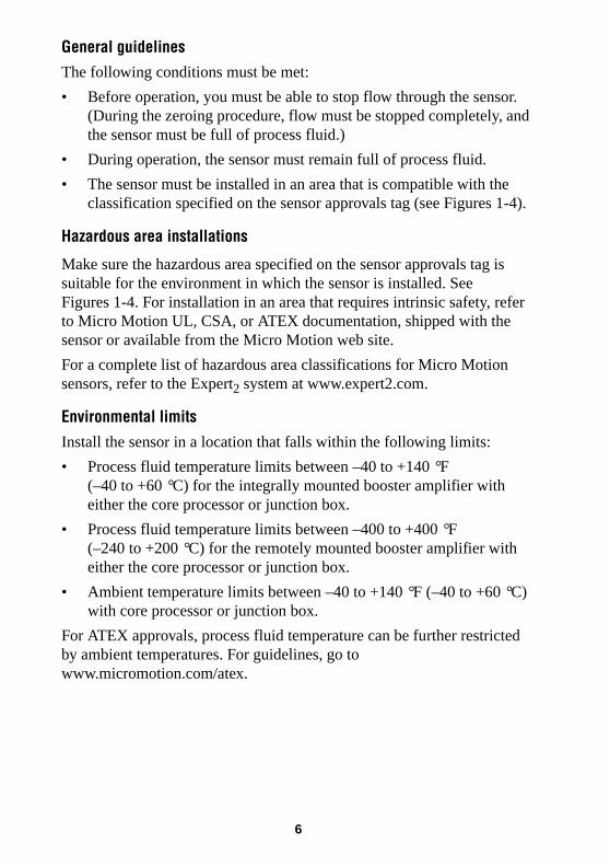
General guidelinesThe following conditions must be met:
• Before operation, you must be able to stop flow through the sensor. (During the zeroing procedure, flow must be stopped completely, and the sensor must be full of process fluid.)
• During operation, the sensor must remain full of process fluid.
• The sensor must be installed in an area that is compatible with the classification specified on the sensor approvals tag (see Figures 1-4).
Hazardous area installations
Make sure the hazardous area specified on the sensor approvals tag is suitable for the environment in which the sensor is installed. See Figures 1-4. For installation in an area that requires intrinsic safety, refer to Micro Motion UL, CSA, or ATEX documentation, shipped with the sensor or available from the Micro Motion web site.
For a complete list of hazardous area classifications for Micro Motion sensors, refer to the Expert2 system at www.expert2.com.
Environmental limits
Install the sensor in a location that falls within the following limits:
• Process fluid temperature limits between –40 to +140 °F (–40 to +60 °C) for the integrally mounted booster amplifier with either the core processor or junction box.
• Process fluid temperature limits between –400 to +400 °F (–240 to +200 °C) for the remotely mounted booster amplifier with either the core processor or junction box.
• Ambient temperature limits between –40 to +140 °F (–40 to +60 °C) with core processor or junction box.
For ATEX approvals, process fluid temperature can be further restricted by ambient temperatures. For guidelines, go to www.micromotion.com/atex.
6
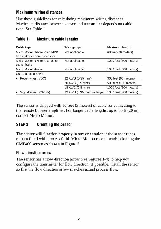
Maximum wiring distancesUse these guidelines for calculating maximum wiring distances. Maximum distance between sensor and transmitter depends on cable type. See Table 1.
.
The sensor is shipped with 10 feet (3 meters) of cable for connecting to the remote booster amplifier. For longer cable lengths, up to 60 ft (20 m), contact Micro Motion.
STEP 2. Orienting the sensor
The sensor will function properly in any orientation if the sensor tubes remain filled with process fluid. Micro Motion recommends orienting the CMF400 sensor as shown in Figure 5.
Flow direction arrow
The sensor has a flow direction arrow (see Figures 1-4) to help you configure the transmitter for flow direction. If possible, install the sensor so that the flow direction arrow matches actual process flow.
Table 1. Maximum cable lengths
Cable type Wire gauge Maximum length
Micro Motion 9-wire to an MVD transmitter or core processor
Not applicable 60 feet (20 meters)
Micro Motion 9-wire to all other transmitters
Not applicable 1000 feet (300 meters)
Micro Motion 4-wire Not applicable 1000 feet (300 meters)
User-supplied 4-wire
• Power wires (VDC) 22 AWG (0,35 mm2) 300 feet (90 meters)
20 AWG (0,5 mm2) 500 feet (150 meters)
18 AWG (0,8 mm2) 1000 feet (300 meters)
• Signal wires (RS-485) 22 AWG (0,35 mm2) or larger 1000 feet (300 meters)
7
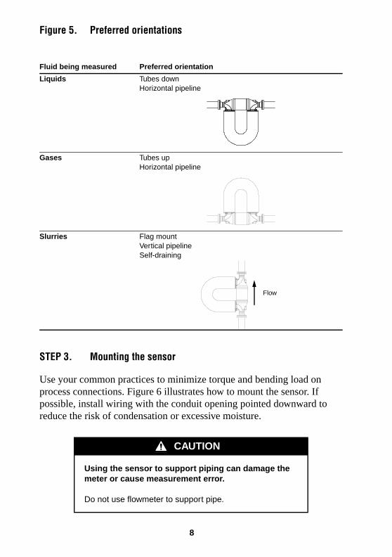
Figure 5. Preferred orientations
STEP 3. Mounting the sensor
Use your common practices to minimize torque and bending load on process connections. Figure 6 illustrates how to mount the sensor. If possible, install wiring with the conduit opening pointed downward to reduce the risk of condensation or excessive moisture.
Fluid being measured Preferred orientation
Liquids Tubes downHorizontal pipeline
Gases Tubes upHorizontal pipeline
Slurries Flag mountVertical pipelineSelf-draining
CAUTION
Using the sensor to support piping can damage the meter or cause measurement error.
Do not use flowmeter to support pipe.
Flow
8
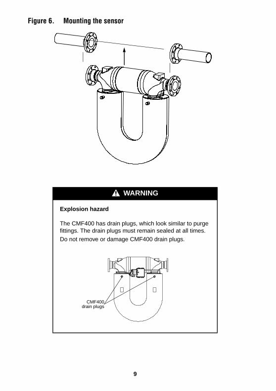
Figure 6. Mounting the sensor
WARNING
Explosion hazard
The CMF400 has drain plugs, which look similar to purge fittings. The drain plugs must remain sealed at all times.
Do not remove or damage CMF400 drain plugs.
CMF400drain plugs
9
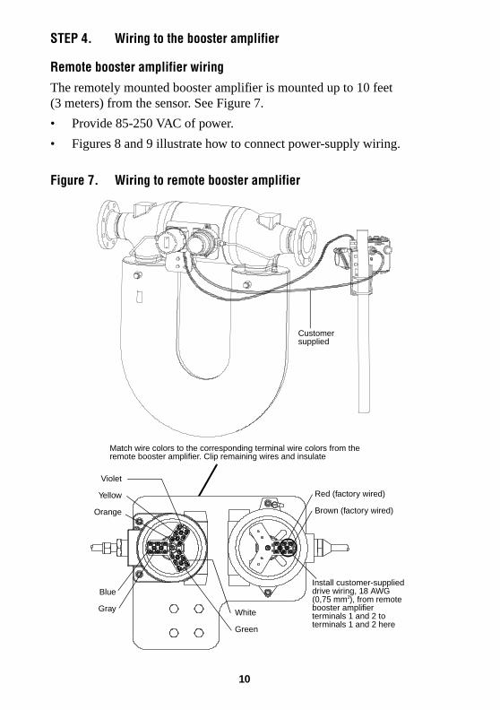
STEP 4. Wiring to the booster amplifier
Remote booster amplifier wiringThe remotely mounted booster amplifier is mounted up to 10 feet (3 meters) from the sensor. See Figure 7.
• Provide 85-250 VAC of power.
• Figures 8 and 9 illustrate how to connect power-supply wiring.
Figure 7. Wiring to remote booster amplifier
Match wire colors to the corresponding terminal wire colors from the remote booster amplifier. Clip remaining wires and insulate
Customer supplied
Install customer-supplied drive wiring, 18 AWG (0,75 mm2), from remote booster amplifier terminals 1 and 2 to terminals 1 and 2 here
Violet
Yellow
Orange
Red (factory wired)
Brown (factory wired)
Blue
Gray White
Green
10
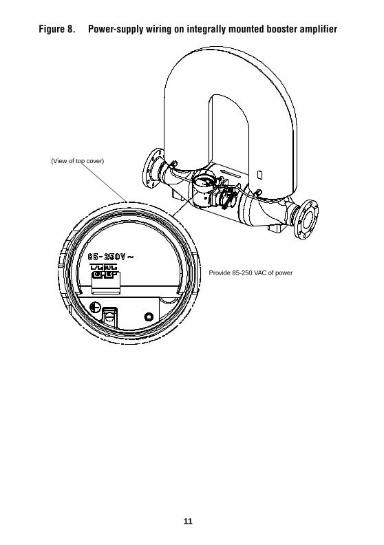
Figure 8. Power-supply wiring on integrally mounted booster amplifier
Provide 85-250 VAC of power
(View of top cover)
11
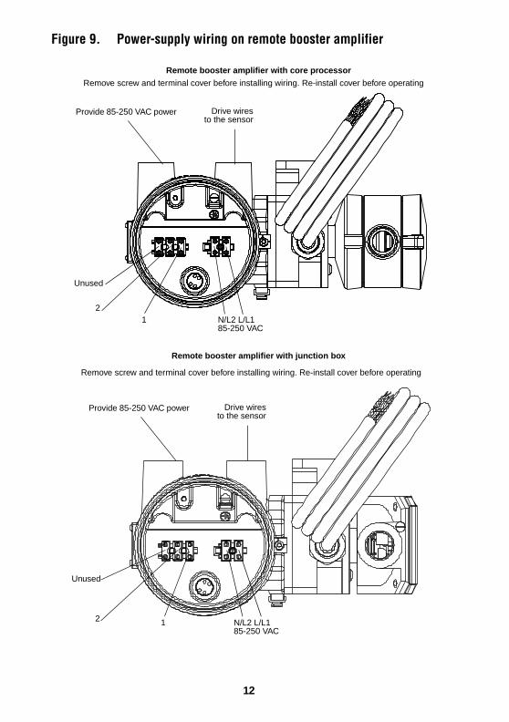
Figure 9. Power-supply wiring on remote booster amplifier
Drive wiresto the sensor
Remote booster amplifier with core processor
Provide 85-250 VAC power
Remote booster amplifier with junction box
Unused
2
2N/L2 L/L185-250 VAC
N/L2 L/L185-250 VAC
1
Drive wiresto the sensor
Provide 85-250 VAC power
1
Remove screw and terminal cover before installing wiring. Re-install cover before operating
Remove screw and terminal cover before installing wiring. Re-install cover before operating
Unused
12
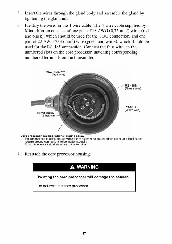
STEP 5. Wiring the sensor to the transmitter
Installation options
The sensor has one of the following configurations:
• A core processor to a 4-wire remote transmitter or remote host (requires a 4-wire cable); see Core processor to a 4-wire remote transmitter or remote host, page 14.
• 9-wire junction box to a remote transmitter (requires a 9-wire cable); see 9-wire junction box cable wiring, page 19.
WARNING
Failure to comply with requirements for intrinsic safety in a hazardous area could result in an explosion.
• For installation in an area that requires intrinsic safety, refer to Micro Motion UL, CSA, or ATEX documentation, shipped with the sensor or available from the Micro Motion web site.
• For hazardous area installations in Europe, refer to standard EN 60079-14 if national standards do not apply.
CAUTION
Failure to seal the sensor and transmitter housings could cause a short circuit, which would result in measurement error or flowmeter failure.
• Ensure integrity of gaskets and O-rings.• Grease all O-rings before sealing.
• Install drip legs in cable or conduit.
• Seal all conduit openings.
13
Core processor to a 4-wire remote transmitter or remote hostTo connect wiring at the core processor:
1. Use one of the following methods to shield the wiring from the core processor to the remote transmitter:
• If you are installing unshielded wiring in continuous metallic conduit that provides 360° termination shielding for the enclosed wiring, go to Step 6, page 17.
• If you are installing user-supplied cable gland with shielded cable or armored cable, terminate the shields in the cable gland. Terminate both the armored braid and the shield drain wires in the cable gland.
• If you are installing a Micro Motion-supplied cable gland at the core processor housing:
- Prepare the cable and apply shielded heat shrink as described below. The shielded heat shrink provides a shield termination suitable for use in the gland when using cable whose shield consists of foil and not a braid. Proceed to Step 2.
- With armored cable, where the shield consists of braid, prepare the cable as described below, but do not apply heat shrink. Proceed to Step 2.
2. Remove the cover from the core processor.
3. Slide the gland nut and the clamping insert over the cable.
14
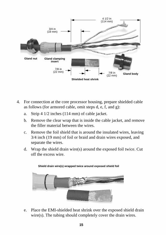
4. For connection at the core processor housing, prepare shielded cable as follows (for armored cable, omit steps d, e, f, and g):
a. Strip 4 1/2 inches (114 mm) of cable jacket.
b. Remove the clear wrap that is inside the cable jacket, and remove the filler material between the wires.
c. Remove the foil shield that is around the insulated wires, leaving 3/4 inch (19 mm) of foil or braid and drain wires exposed, and separate the wires.
d. Wrap the shield drain wire(s) around the exposed foil twice. Cut off the excess wire.
e. Place the EMI-shielded heat shrink over the exposed shield drain wire(s). The tubing should completely cover the drain wires.
4 1/2 in(114 mm)
3/4 in(19 mm)
7/8 in (22 mm) 7/8 in
(22 mm)Shielded heat shrink
Gland body
Gland nut Gland clamping insert
Shield drain wire(s) wrapped twice around exposed shield foil
15
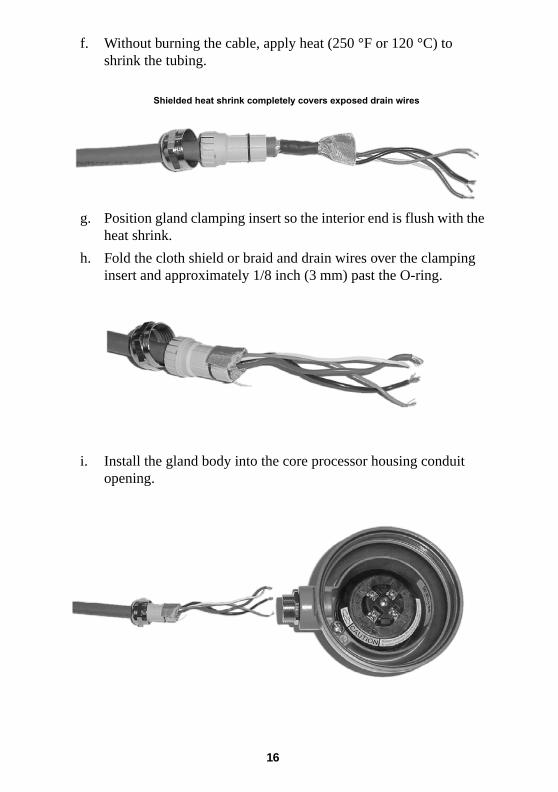
f. Without burning the cable, apply heat (250 °F or 120 °C) to shrink the tubing.
g. Position gland clamping insert so the interior end is flush with the heat shrink.
h. Fold the cloth shield or braid and drain wires over the clamping insert and approximately 1/8 inch (3 mm) past the O-ring.
i. Install the gland body into the core processor housing conduit opening.
����������������� ����������������������������������
16
�� ��������������� ���������� ����������������������
��������������������
�� ������������������������������������������������������
���� � �� �� ������ � ������ ��� !"#$%&���'(�����#���
�������)(%���� ���������� ���*+,� ������ �%��� ��
���� �'' !"#$%-���'(����#������������(%���� �����
����� ���./����� ������ ��, �������� �������� ��
���������� �� ���� ���� ���� �%�������� ����� �����
����������������� ���������������
&� .��������� ���� ���� � ������
�������
������������������������������������������
������������������� ��������
������� ������������
������� ���������������
����� !��"�������
����� ���#�������
!��������������"���������������"�������$ %���������������������&����������������������'�&�������(��� � ��&����������������
�)����&��������������������'�*������������$ ���������������������������������������*����
��
�� /���������������������#�(� ���� ����� ���������
������������
0 1 ����������������������%����������������2���).��������
"����#2."(�
0 ��� ����� ��������� ���*+/ � ����*++�����, �����3
��/���������������������� � �� �%������������������ ����
��� ���� ���� ��.����� ���������� ��������� �� ����������
���������������������
0 ��� ����� ��������� ���*+/ � ��� ����/��������4
� , �������*+,������� ���� ���� ���� �#���1����� �$(
� �������������� �������������� �������������� �����
���� ��� ���� ���� �� ��� �������� �������������
/+5������ �'��*+,� �������������������������
/ ��67�8��+����
� + � ��� ��������� ������ � ���� ����������
� , �������./����������� ���� ���� ���� �#���
1����� �$(� ��./�������������������� �� ���.�����
��8��� �� ��������� �� ��������������������
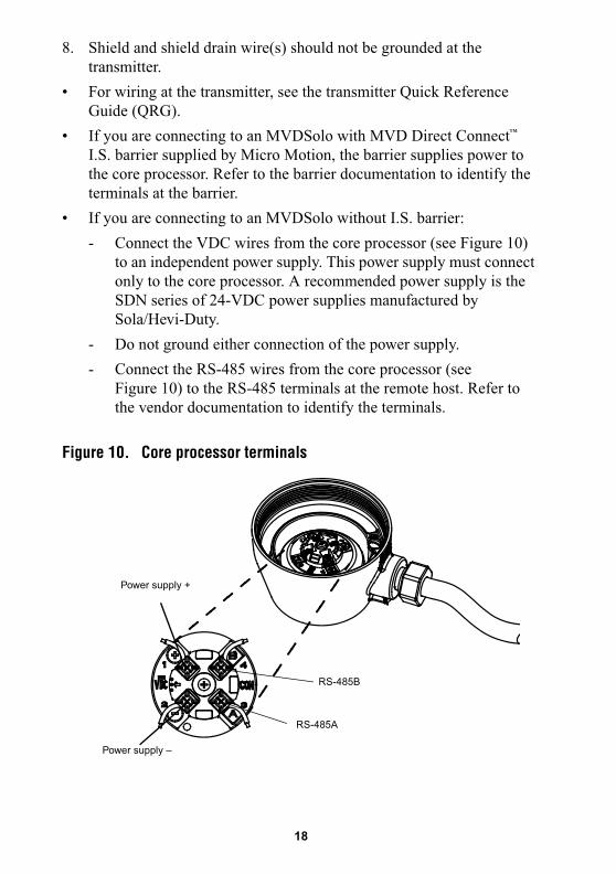
Figure 10. Core processor terminals
������� �����
������� ����
����� ��
����� !�
�#
9-wire junction box cable wiring1 �� ����������� �� � �������9����������������������� �
�����������������
�� :�������������������������� ������ ����������� ��������
� �� �;������������ ��������������� ���������� �� ���
������
'� �������������������� �������8������������� ����������
�� �)��5 ���������� ����������<� ����
-� ������������ � �� �� � ��1 ����������������������%������
�������������2."�
�� ��������������� �����������������
�� =�������������� ����)���%����������� �����������>����� �� <
� 8�������� ������ 8��� ���������������
STEP 6. Grounding the sensor
������ �������� �����8��������������> �������������������
�� ����� ������������� ���� ��� �����8����������%� ������
�� �������� ���������� ��<�������� �����������%������ �����
���� ���� ���� � �>����� �� <�
!�%��&�
������������"��������"�����"�����"�����������
+���������������,�*����*�������-
$ #��������,���*���������.����,������&������
��������)���*����,�����,��������
$ %�������������������������������)�����������������,��.�
�,�����/�����/������01.�2�!.����!+34�
����*�������.��� ������������������(����'��
,��*���/�����/�������'�����
$ %����5����������������������������3��� .��,�����
���������36�7889:�;���,���������������������������
� ���
�$

������ ���������������� ���������%� �� ���������������4
0 ?��� ��������%�� !"#'%���@( �������������A�� �
�� �������
0 B�������� ����������� ����� ������%�������� �
����������
0 , ������� ����������������� ����% �� �� ����������������
.����� �������������� ��������� �� ���������� �� ��� ��������
������������
'(


Micro MotionTM
©2003, Micro Motion, Inc. All rights reserved. P/N 3006075, Rev. D
*3006075*
Visit us on the Internet at www.micromotion.com
Micro Motion Inc. USAWorldwide Headquarters7070 Winchester CircleBoulder, Colorado 80301T (303) 530-8400
(800) 522-6277F (303) 530-8459
Micro Motion EuropeEmerson Process ManagementWiltonstraat 303905 KW VeenendaalThe NetherlandsT +31 (0) 318 495 670F +31 (0) 318 495 689
Micro Motion United KingdomEmerson Process Management LimitedHorsfield WayBredbury Industrial EstateStockport SK6 2SU U.K.T 0800 966 180F 0800 966 181
Micro Motion JapanEmerson Process ManagementShinagawa NF Bldg. 5F1-2-5, Higashi ShinagawaShinagawa-kuTokyo 140-0002 JapanT (81) 3 5769-6803F (81) 3 5769-6843
Micro Motion AsiaEmerson Process Management1 Pandan CrescentSingapore 128461Republic of SingaporeT (65) 6777-8211F (65) 6770-8003