Embed Size (px)
Citation preview
1
INSTRUCTION MANUAL
MICRO-COMPUTER BASED DIGITAL INDICATOR FIR-201-M No.FIR21E8 2003.08 To prevent accidents arising from the misuse of this controller, please ensure the operator using it receives this manual.
Warning Turn the power supplied to the instrument OFF before wiring or checking it. Working or touching the terminal with the power switched ON may result in severe injury or death due to Electric Shock.
Caution Do not apply a commercial power surce to the sensor connected to the input terminal
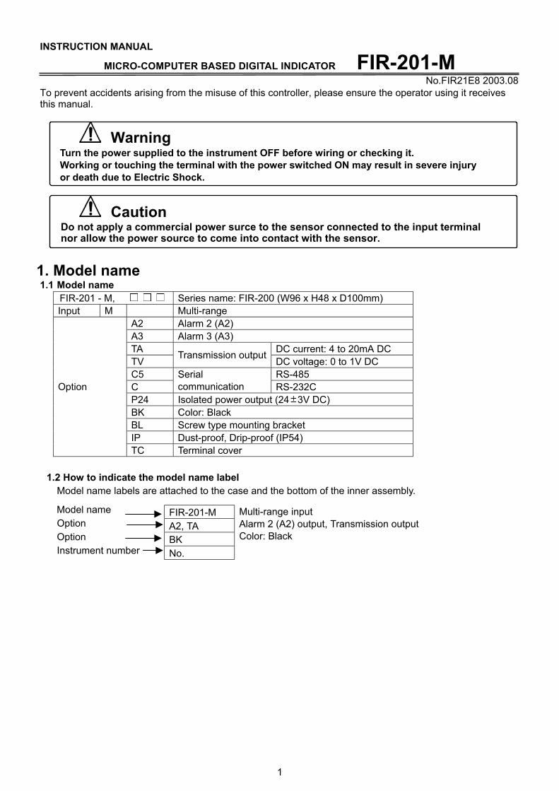
nor allow the power source to come into contact with the sensor. 1. Model name 1.1 Model name
FIR-201 - M, Series name: FIR-200 (W96 x H48 x D100mm) Input M Multi-range
A2 Alarm 2 (A2) A3 Alarm 3 (A3) TA DC current: 4 to 20mA DC TV Transmission output DC voltage: 0 to 1V DC C5 RS-485 C
Serial communication RS-232C
P24 Isolated power output (24 3V DC) BK Color: Black BL Screw type mounting bracket IP Dust-proof, Drip-proof (IP54)
Option
TC Terminal cover 1.2 How to indicate the model name label
Model name labels are attached to the case and the bottom of the inner assembly.
Model name Option Option Instrument number
FIR-201-M A2, TA BK No.
Multi-range input Alarm 2 (A2) output, Transmission output Color: Black
2
2. Name and functions of the sections
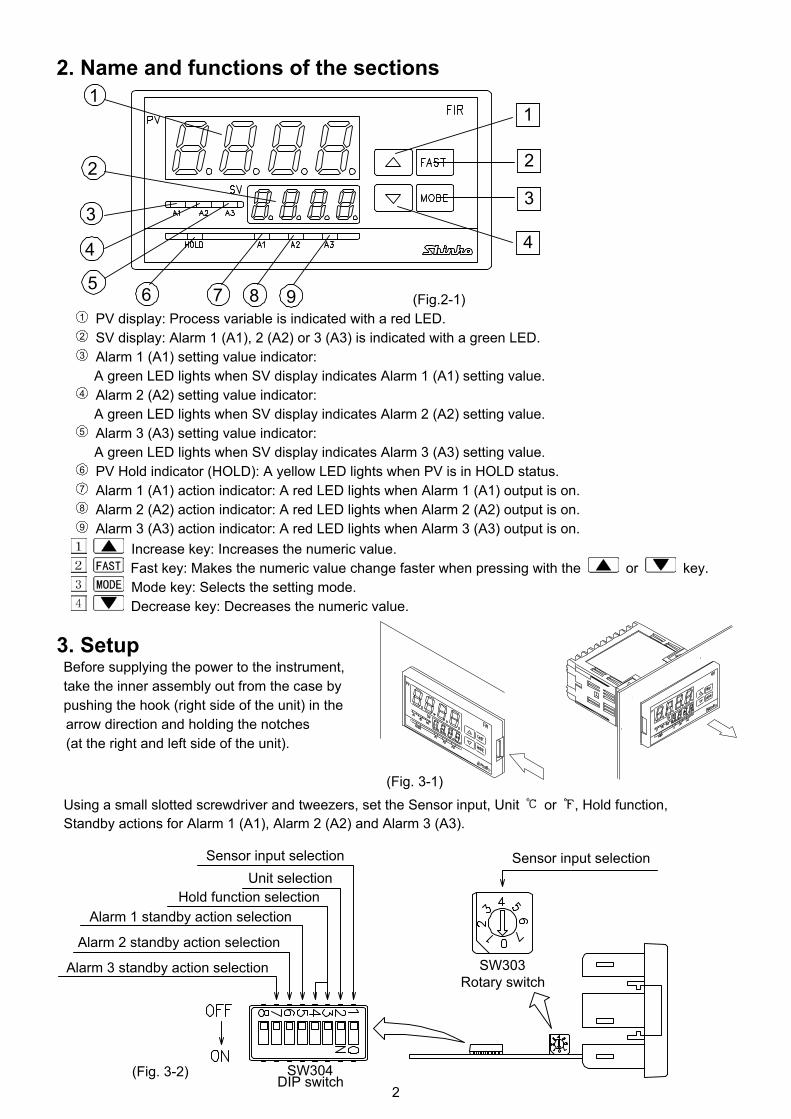
(Fig.2-1) 1 PV display: Process variable is indicated with a red LED. 2 SV display: Alarm 1 (A1), 2 (A2) or 3 (A3) is indicated with a green LED. 3 Alarm 1 (A1) setting value indicator:
A green LED lights when SV display indicates Alarm 1 (A1) setting value. 4 Alarm 2 (A2) setting value indicator:
A green LED lights when SV display indicates Alarm 2 (A2) setting value. 5 Alarm 3 (A3) setting value indicator:
A green LED lights when SV display indicates Alarm 3 (A3) setting value. 6 PV Hold indicator (HOLD): A yellow LED lights when PV is in HOLD status. 7 Alarm 1 (A1) action indicator: A red LED lights when Alarm 1 (A1) output is on. 8 Alarm 2 (A2) action indicator: A red LED lights when Alarm 2 (A2) output is on. 9 Alarm 3 (A3) action indicator: A red LED lights when Alarm 3 (A3) output is on. Increase key: Increases the numeric value. Fast key: Makes the numeric value change faster when pressing with the or key. Mode key: Selects the setting mode. Decrease key: Decreases the numeric value.
3. Setup Before supplying the power to the instrument, take the inner assembly out from the case by pushing the hook (right side of the unit) in the
arrow direction and holding the notches (at the right and left side of the unit).
(Fig. 3-1)
Using a small slotted screwdriver and tweezers, set the Sensor input, Unit or , Hold function, Standby actions for Alarm 1 (A1), Alarm 2 (A2) and Alarm 3 (A3). (Fig. 3-2)
Sensor input selection
SW303Rotary switch
SW304DIP switch
Unit selectionHold function selection
Alarm 1 standby action selection
Alarm 2 standby action selection
Alarm 3 standby action selection
Sensor input selection
5
4
3
98
1
2
76
1
2
3
4
3
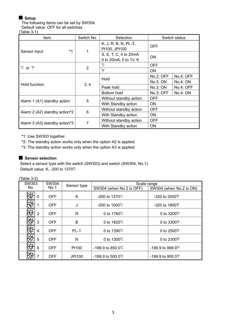
Setup The following items can be set by SW304. Default value: OFF for all switches.
(Table 3-1) Item Switch No. Selection Switch status
K, J, R, B, N, PL- , Pt100, JPt100 OFF
Sensor input *1 1 S, E, T, C, 4 to 20mA 0 to 20mA, 0 to 1V, K ON
OFF or 2 ON
No.3: OFF No.4: OFF Hold No.3: ON No.4: ON
Peak hold No.3: ON No.4: OFF Hold function 3, 4
Bottom hold No.3: OFF No.4: ON Without standby action OFF Alarm 1 (A1) standby action 5 With Standby action ON Without standby action OFF Alarm 2 (A2) standby action*2 6 With Standby action ON Without standby action OFF Alarm 3 (A3) standby action*3 7 With Standby action ON
*1: Use SW303 together. *2: The standby action works only when the option A2 is applied. *3: The standby action works only when the option A3 is applied.
Sensor selection
Select a sensor type with the switch (SW303) and switch (SW304, No.1). Default value: K, -200 to 1370
(Table 3-2) Scale range SW303
No. SW304
No.1 Sensor type SW304 (when No.2 is OFF) SW304 (when No.2 is ON)
0 OFF K -200 to 1370 -320 to 2500
1 OFF J -200 to 1000 -320 to 1800
2 OFF R 0 to 1760 0 to 3200
3 OFF B 0 to 1820 0 to 3300
4 OFF PL- 0 to 1390 0 to 2500
5 OFF N 0 to 1300 0 to 2300
6 OFF Pt100 -199.9 to 850.0 -199.9 to 999.9
7 OFF JPt100 -199.9 to 500.0 -199.9 to 900.0
4
(Table 3-3) Scale range SW303
No. SW304
No.1 Sensor type SW304 (when No.2 is OFF) SW304 (when No.2 is ON)
0 ON S 0 to 1760 0 to 3200
1 ON E 0 to 1000 0 to 1800
2 ON T -199.9 to 400.0 -199.9 to 750.0
3 ON C(W/Re5-26) 0 to 2315 0 to 4200
4 ON 4 to 20mA DC -1999 to 9999
5 ON 0 to 20mA DC -1999 to 9999
6 ON 0 to 1V DC -1999 to 9999
7 ON K 0.0 to 400.0 0.0 to 750.0 When the setup is completed, insert the internal assembly into the case.
(Do not confuse the top and bottom of the inner assembly. If inserting the assembly into the case in wrong direction, the PCB may be damaged.) Surely insert the assembly until it is locked by the hook at the right of the instrument. (“Click” sounds)
4. Mounting to control panel 4.1 Site selection
Mount the units in a place with: • A minimum of dust, and an absence of corrosive gases • No flammable, explosive gases
• No mechanical vibrations or shocks • No exposure to direct sunlight, an ambient temperature of 0 to 50 (32 to 122 ) without rapid change • An ambient non-condensing humidity of 35 to 85%RH • No large capacity electromagnetic switches or cables through which large current is flowing • No water, oil or chemicals or where the vapors of these substances can come into direct contact with
the controller
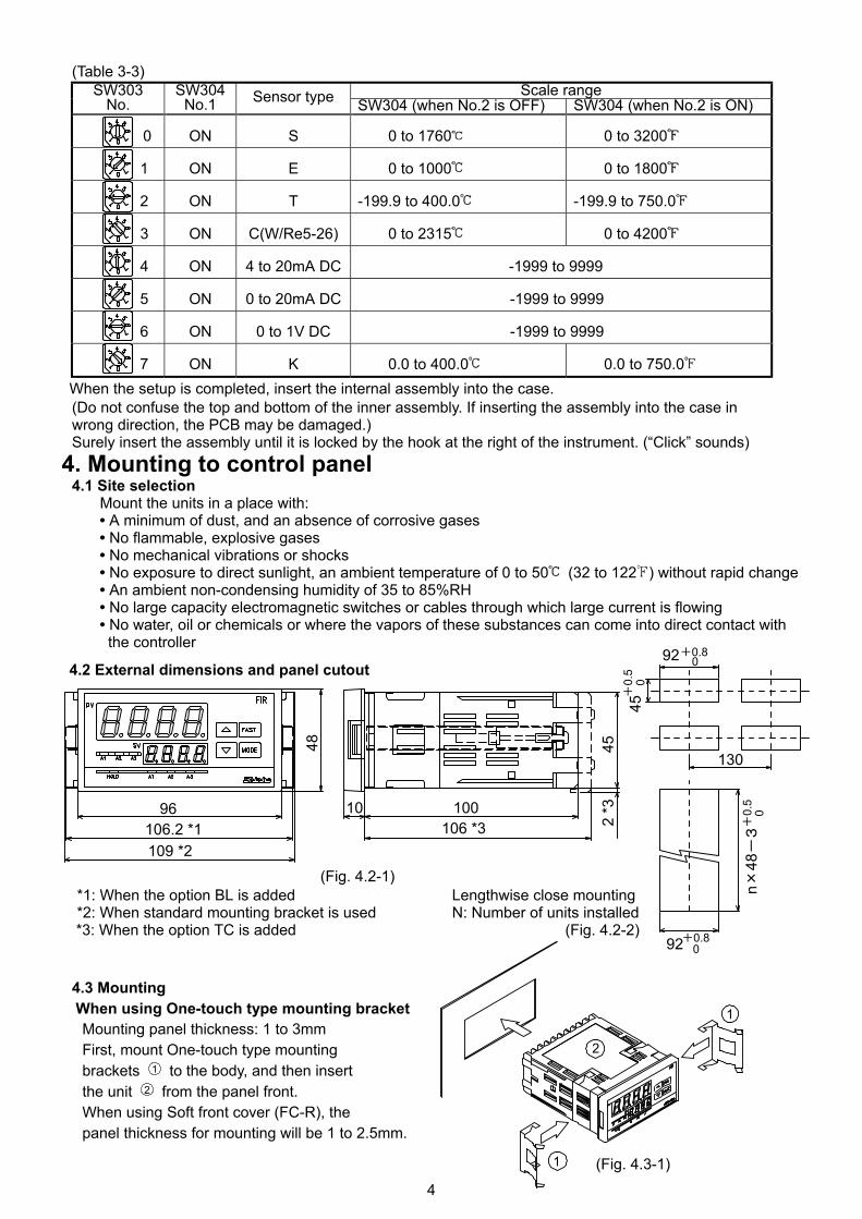
4.2 External dimensions and panel cutout (Fig. 4.2-1) *1: When the option BL is added Lengthwise close mounting
*2: When standard mounting bracket is used N: Number of units installed *3: When the option TC is added (Fig. 4.2-2)
4.3 Mounting When using One-touch type mounting bracket Mounting panel thickness: 1 to 3mm First, mount One-touch type mounting brackets 1 to the body, and then insert the unit 2 from the panel front. When using Soft front cover (FC-R), the panel thickness for mounting will be 1 to 2.5mm.
(Fig. 4.3-1)
1
2
1
96106.2 *1109 *2
48
10 100106 *3
452
*3
45+
0.5
092+0.8
0
130
92+0.80
n ×48
-3+
0.5
0
5
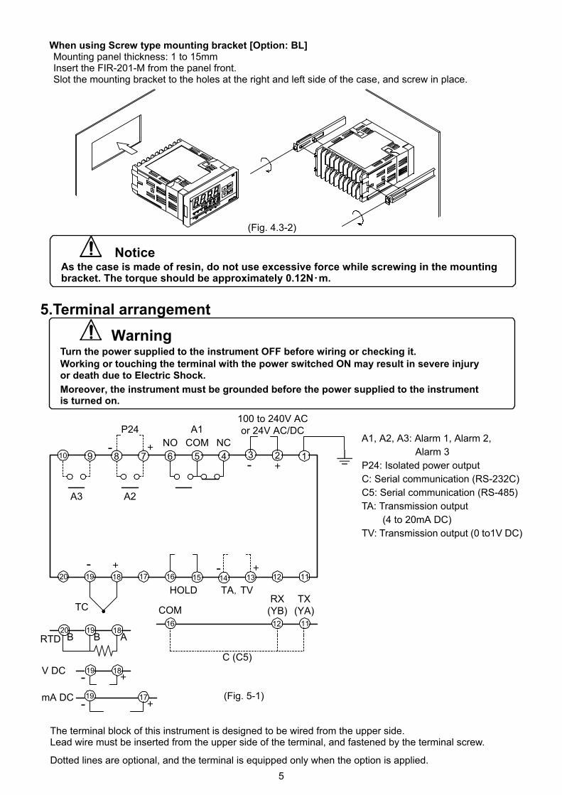
When using Screw type mounting bracket [Option: BL] Mounting panel thickness: 1 to 15mm Insert the FIR-201-M from the panel front. Slot the mounting bracket to the holes at the right and left side of the case, and screw in place.
(Fig. 4.3-2)
Notice As the case is made of resin, do not use excessive force while screwing in the mounting bracket. The torque should be approximately 0.12N・m.
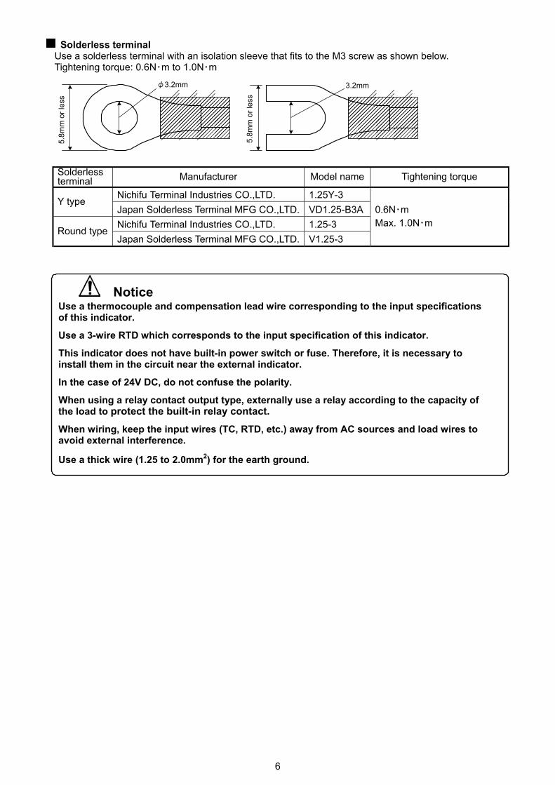
5.Terminal arrangement Warning
Turn the power supplied to the instrument OFF before wiring or checking it. Working or touching the terminal with the power switched ON may result in severe injury or death due to Electric Shock. Moreover, the instrument must be grounded before the power supplied to the instrument is turned on.
A1, A2, A3: Alarm 1, Alarm 2, Alarm 3 P24: Isolated power output C: Serial communication (RS-232C) C5: Serial communication (RS-485)
TA: Transmission output (4 to 20mA DC)
TV: Transmission output (0 to1V DC) (Fig. 5-1)
The terminal block of this instrument is designed to be wired from the upper side. Lead wire must be inserted from the upper side of the terminal, and fastened by the terminal screw.
Dotted lines are optional, and the terminal is equipped only when the option is applied.
100 to 240V ACor 24V AC/DC
NO COM NC
TA,TVHOLD
A1
A2A3
P24
TX(YA)
RX(YB)COM
B B A
-
TC
RTD
V DC
mA DC
+
- +
C (C5)
+- - +
+-+-
15
5 4
14
39 810 12
1213
7 6
1820 19 17 16 11
111216181920
1819
19 17
6
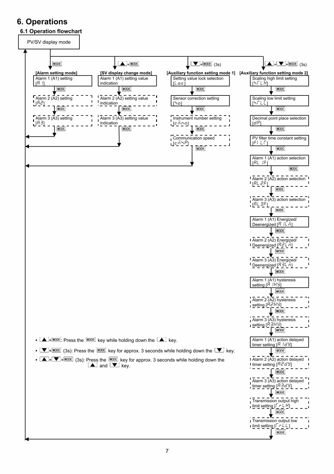
Solderless terminal Use a solderless terminal with an isolation sleeve that fits to the M3 screw as shown below. Tightening torque: 0.6N・m to 1.0N・m
Solderless terminal Manufacturer Model name Tightening torque
Nichifu Terminal Industries CO.,LTD. 1.25Y-3 Y type Japan Solderless Terminal MFG CO.,LTD. VD1.25-B3A Nichifu Terminal Industries CO.,LTD. 1.25-3 Round type Japan Solderless Terminal MFG CO.,LTD. V1.25-3
0.6N・m Max. 1.0N・m
Notice Use a thermocouple and compensation lead wire corresponding to the input specifications of this indicator.
Use a 3-wire RTD which corresponds to the input specification of this indicator.
This indicator does not have built-in power switch or fuse. Therefore, it is necessary to install them in the circuit near the external indicator.
In the case of 24V DC, do not confuse the polarity.
When using a relay contact output type, externally use a relay according to the capacity of the load to protect the built-in relay contact. When wiring, keep the input wires (TC, RTD, etc.) away from AC sources and load wires to avoid external interference.
Use a thick wire (1.25 to 2.0mm2) for the earth ground.
���������������
φ3.2mm
5.8m
m o
r les
s
���������������
3.2mm
5.8m
m o
r les
s
7
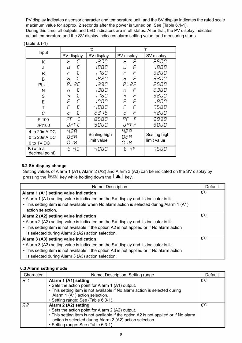
6. Operations 6.1 Operation flowchart
PV/SV display mode
+ + (3s) + + (3s) [Alarm setting mode] [SV display change mode] [Auxiliary function setting mode 1] [Auxiliary function setting mode 2] Alarm 1 (A1) setting [ ]
Alarm 1 (A1) setting value indication
Setting value lock selection [ ]
Scaling high limit setting [ ]
Alarm 2 (A2) setting [ ]
Alarm 2 (A2) setting value indication
Sensor correction setting [ ]
Scaling low limit setting [ ]
Alarm 3 (A3) setting [ ]
Alarm 3 (A3) setting value indication
Instrument number setting [ ]
Decimal point place selection [ ]
Communication speed [ ]
PV filter time constant setting [ ]
Alarm 1 (A1) action selection [ ]
Alarm 2 (A2) action selection [ ]
Alarm 3 (A3) action selection [ ]
Alarm 1 (A1) Energized/ Deenergized [ ]
Alarm 2 (A2) Energized/
Deenergized [ ]
Alarm 3 (A3) Energized/ Deenergized [ ]
Alarm 1 (A1) hysteresis
setting [ ] Alarm 2 (A2) hysteresis
setting [ ] Alarm 3 (A3) hysteresis
setting [ ] • + : Press the key while holding down the key. Alarm 1 (A1) action delayed
timer setting [ ] • + (3s): Press the key for approx. 3 seconds while holding down the key. • + + (3s): Press the key for approx. 3 seconds while holding down the
and key. Alarm 2 (A2) action delayed timer setting [ ]
Alarm 3 (A3) action delayed
timer setting [ ] Transmission output high
limit setting [ ]
Transmission output low limit setting [ ]
8
PV display indicates a sensor character and temperature unit, and the SV display indicates the rated scale maximum value for approx. 2 seconds after the power is turned on. See (Table 6.1-1). During this time, all outputs and LED indicators are in off status. After that, the PV display indicates
actual temperature and the SV display indicates alarm setting value, and measuring starts. (Table 6.1-1)
Input PV display SV display PV display SV display
K J R B
PL- N S E T C
Pt100 JPt100
4 to 20mA DC 0 to 20mA DC 0 to 1V DC
Scaling high limit value
Scaling high limit value
K (with a decimal point)
6.2 SV display change Setting values of Alarm 1 (A1), Alarm 2 (A2) and Alarm 3 (A3) can be indicated on the SV display by pressing the key while holding down the key.
Name, Description Default Alarm 1 (A1) setting value indication • Alarm 1 (A1) setting value is indicated on the SV display and its indicator is lit. • This setting item is not available when No alarm action is selected during Alarm 1 (A1)
action selection.
0
Alarm 2 (A2) setting value indication • Alarm 2 (A2) setting value is indicated on the SV display and its indicator is lit. • This setting item is not available if the option A2 is not applied or if No alarm action
is selected during Alarm 2 (A2) action selection.
0
Alarm 3 (A3) setting value indication • Alarm 3 (A3) setting value is indicated on the SV display and its indicator is lit. • This setting item is not available if the option A3 is not applied or if No alarm action
is selected during Alarm 3 (A3) action selection.
0
6.3 Alarm setting mode
Character Name, Description, Setting range Default Alarm 1 (A1) setting
• Sets the action point for Alarm 1 (A1) output. • This setting item is not available if No alarm action is selected during
Alarm 1 (A1) action selection. • Setting range: See (Table 6.3-1).
0
Alarm 2 (A2) setting • Sets the action point for Alarm 2 (A2) output. • This setting item is not available if the option A2 is not applied or if No alarm
action is selected during Alarm 2 (A2) action selection. • Setting range: See (Table 6.3-1).
0
9
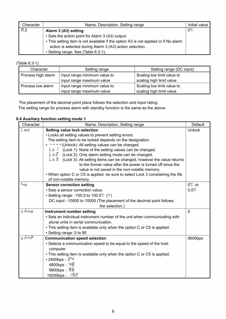
Character Name, Description, Setting range Initial value
Alarm 3 (A3) setting • Sets the action point for Alarm 3 (A3) output. • This setting item is not available if the option A3 is not applied or if No alarm
action is selected during Alarm 3 (A3) action selection. • Setting range: See (Table 6.3-1).
0
(Table 6.3-1)
Character Setting range Setting range (DC input) Process high alarm Input range minimum value to
input range maximum value Scaling low limit value to scaling high limit value
Process low alarm Input range minimum value to input range maximum value
Scaling low limit value to scaling high limit value
The placement of the decimal point place follows the selection and input rating.
The setting range for process alarm with standby function is the same as the above. 6.4 Auxiliary function setting mode 1
Character Name, Description, Setting range Default Setting value lock selection
• Locks all setting values to prevent setting errors. The setting item to be locked depends on the designation. • (Unlock): All setting values can be changed.
(Lock 1): None of the setting values can be changed. (Lock 2): Only alarm setting mode can be changed. (Lock 3): All setting items can be changed, however the value returns
to the former value after the power is turned off since the value is not saved in the non-volatile memory.
• When option C or C5 is applied, be sure to select Lock 3 considering the life of non-volatile memory.
Unlock
Sensor correction setting • Sets a sensor correction value. • Setting range: -100.0 to 100.0 ( )
DC input: -10000 to 10000 (The placement of the decimal point follows the selection.)
0 or 0.0
Instrument number setting • Sets an individual instrument number of the unit when communicating with
plural units in serial communication. • This setting item is available only when the option C or C5 is applied. • Setting range: 0 to 95
0
Communication speed selection • Selects a communication speed to be equal to the speed of the host
computer. • This setting item is available only when the option C or C5 is applied. • 2400bps: 4800bps: 9600bps: 19200bps:
9600bps
10
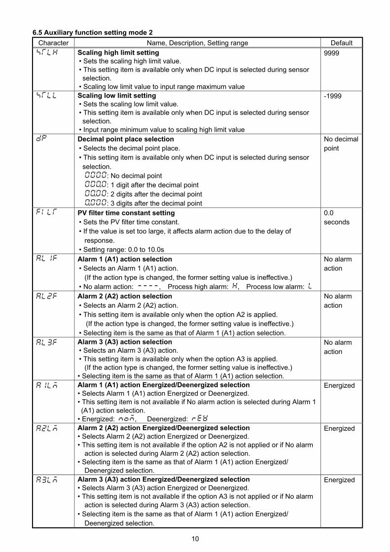
6.5 Auxiliary function setting mode 2 Character Name, Description, Setting range Default
Scaling high limit setting • Sets the scaling high limit value. • This setting item is available only when DC input is selected during sensor selection. • Scaling low limit value to input range maximum value
9999
Scaling low limit setting • Sets the scaling low limit value. • This setting item is available only when DC input is selected during sensor selection. • Input range minimum value to scaling high limit value
-1999
Decimal point place selection • Selects the decimal point place. • This setting item is available only when DC input is selected during sensor selection.
: No decimal point : 1 digit after the decimal point : 2 digits after the decimal point : 3 digits after the decimal point
No decimal point
PV filter time constant setting • Sets the PV filter time constant. • If the value is set too large, it affects alarm action due to the delay of
response. • Setting range: 0.0 to 10.0s
0.0 seconds
Alarm 1 (A1) action selection • Selects an Alarm 1 (A1) action.
(If the action type is changed, the former setting value is ineffective.) • No alarm action: , Process high alarm: , Process low alarm:
No alarm action
Alarm 2 (A2) action selection • Selects an Alarm 2 (A2) action. • This setting item is available only when the option A2 is applied.
(If the action type is changed, the former setting value is ineffective.) • Selecting item is the same as that of Alarm 1 (A1) action selection.
No alarm action
Alarm 3 (A3) action selection • Selects an Alarm 3 (A3) action. • This setting item is available only when the option A3 is applied.
(If the action type is changed, the former setting value is ineffective.) • Selecting item is the same as that of Alarm 1 (A1) action selection.
No alarm action
Alarm 1 (A1) action Energized/Deenergized selection • Selects Alarm 1 (A1) action Energized or Deenergized. • This setting item is not available if No alarm action is selected during Alarm 1 (A1) action selection. • Energized: , Deenergized:
Energized
Alarm 2 (A2) action Energized/Deenergized selection • Selects Alarm 2 (A2) action Energized or Deenergized. • This setting item is not available if the option A2 is not applied or if No alarm
action is selected during Alarm 2 (A2) action selection. • Selecting item is the same as that of Alarm 1 (A1) action Energized/
Deenergized selection.
Energized
Alarm 3 (A3) action Energized/Deenergized selection • Selects Alarm 3 (A3) action Energized or Deenergized. • This setting item is not available if the option A3 is not applied or if No alarm
action is selected during Alarm 3 (A3) action selection. • Selecting item is the same as that of Alarm 1 (A1) action Energized/
Deenergized selection.
Energized
11
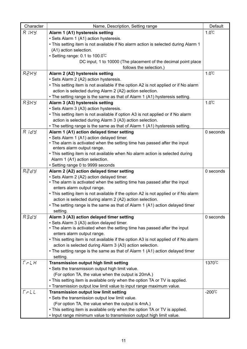
Character Name, Description, Setting range Default
Alarm 1 (A1) hysteresis setting • Sets Alarm 1 (A1) action hysteresis. • This setting item is not available if No alarm action is selected during Alarm 1 (A1) action selection. • Setting range: 0.1 to 100.0
DC input, 1 to 10000 (The placement of the decimal point place follows the selection.)
1.0
Alarm 2 (A2) hysteresis setting • Sets Alarm 2 (A2) action hysteresis. • This setting item is not available if the option A2 is not applied or if No alarm
action is selected during Alarm 2 (A2) action selection. • The setting range is the same as that of Alarm 1 (A1) hysteresis setting.
1.0
Alarm 3 (A3) hysteresis setting • Sets Alarm 3 (A3) action hysteresis. • This setting item is not available if option A3 is not applied or if No alarm
action is selected during Alarm 3 (A3) action selection. • The setting range is the same as that of Alarm 1 (A1) hysteresis setting.
1.0
Alarm 1 (A1) action delayed timer setting • Sets Alarm 1 (A1) action delayed timer. • The alarm is activated when the setting time has passed after the input
enters alarm output range. • This setting item is not available when No alarm action is selected during Alarm 1 (A1) action selection. • Setting range 0 to 9999 seconds
0 seconds
Alarm 2 (A2) action delayed timer setting • Sets Alarm 2 (A2) action delayed timer. • The alarm is activated when the setting time has passed after the input
enters alarm output range. • This setting item is not available if the option A2 is not applied or if No alarm
action is selected during alarm 2 (A2) action selection. • The setting range is the same as that of Alarm 1 (A1) action delayed timer
setting.
0 seconds
Alarm 3 (A3) action delayed timer setting • Sets Alarm 3 (A3) action delayed timer. • The alarm is activated when the setting time has passed after the input
enters alarm output range. • This setting item is not available if the option A3 is not applied of if No alarm
action is selected during Alarm 3 (A3) action selection. • The setting range is the same as that of Alarm 1 (A1) action delayed timer
setting.
0 seconds
Transmission output high limit setting • Sets the transmission output high limit value. (For option TA, the value when the output is 20mA.) • This setting item is available only when the option TA or TV is applied. • Transmission output low limit value to input range maximum value.
1370
Transmission output low limit setting • Sets the transmission output low limit value. (For option TA, the value when the output is 4mA.) • This setting item is available only when the option TA or TV is applied. • Input range minimum value to transmission output high limit value.
-200
12
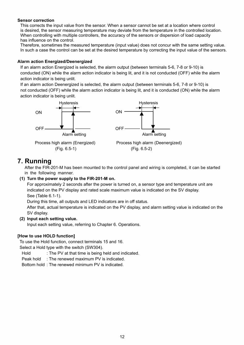
Sensor correction This corrects the input value from the sensor. When a sensor cannot be set at a location where control is desired, the sensor measuring temperature may deviate from the temperature in the controlled location. When controlling with multiple controllers, the accuracy of the sensors or dispersion of load capacity has influence on the control. Therefore, sometimes the measured temperature (input value) does not concur with the same setting value. In such a case the control can be set at the desired temperature by correcting the input value of the sensors.
Alarm action Energized/Deenergized
If an alarm action Energized is selected, the alarm output (between terminals 5-6, 7-8 or 9-10) is conducted (ON) while the alarm action indicator is being lit, and it is not conducted (OFF) while the alarm action indicator is being unlit. If an alarm action Deenergized is selected, the alarm output (between terminals 5-6, 7-8 or 9-10) is not conducted (OFF) while the alarm action indicator is being lit, and it is conducted (ON) while the alarm action indicator is being unlit.
Process high alarm (Energized) Process high alarm (Deenergized)
(Fig. 6.5-1) (Fig. 6.5-2) 7. Running
After the FIR-201-M has been mounted to the control panel and wiring is completed, it can be started in the following manner.
(1) Turn the power supply to the FIR-201-M on. For approximately 2 seconds after the power is turned on, a sensor type and temperature unit are indicated on the PV display and rated scale maximum value is indicated on the SV display. See (Table 6.1-1). During this time, all outputs and LED indicators are in off status. After that, actual temperature is indicated on the PV display, and alarm setting value is indicated on the SV display.
(2) Input each setting value. Input each setting value, referring to Chapter 6. Operations.
[How to use HOLD function] To use the Hold function, connect terminals 15 and 16. Select a Hold type with the switch (SW304). Hold : The PV at that time is being held and indicated.
Peak hold : The renewed maximum PV is indicated. Bottom hold : The renewed minimum PV is indicated.
ON
OFF
Hysteresis
Alarm setting
ON
OFF
Hysteresis
Alarm setting
13
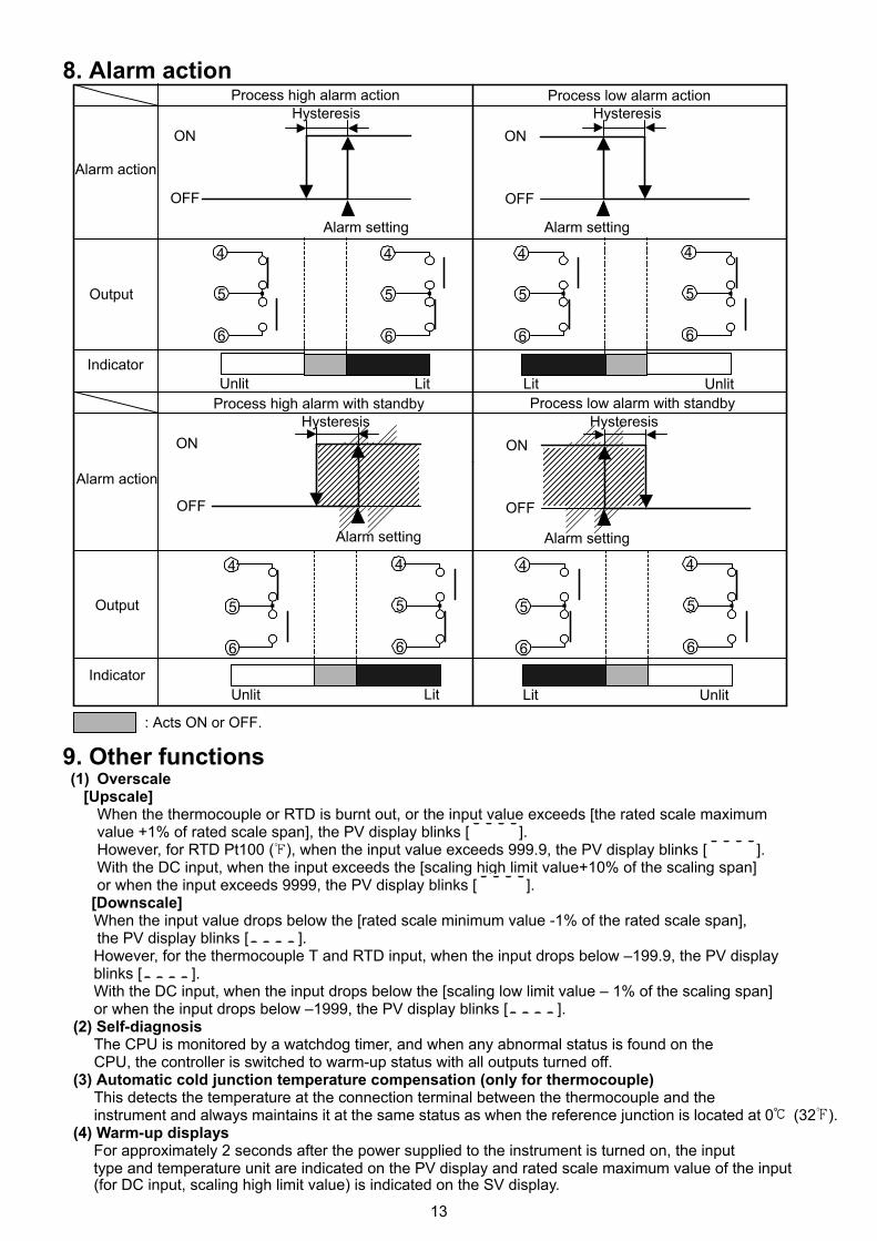
8. Alarm action 9. Other functions (1) Overscale
[Upscale] When the thermocouple or RTD is burnt out, or the input value exceeds [the rated scale maximum value +1% of rated scale span], the PV display blinks [ ]. However, for RTD Pt100 ( ), when the input value exceeds 999.9, the PV display blinks [ ]. With the DC input, when the input exceeds the [scaling high limit value+10% of the scaling span] or when the input exceeds 9999, the PV display blinks [ ].
[Downscale] When the input value drops below the [rated scale minimum value -1% of the rated scale span],
the PV display blinks [ ]. However, for the thermocouple T and RTD input, when the input drops below –199.9, the PV display blinks [ ].
With the DC input, when the input drops below the [scaling low limit value – 1% of the scaling span] or when the input drops below –1999, the PV display blinks [ ].
(2) Self-diagnosis The CPU is monitored by a watchdog timer, and when any abnormal status is found on the CPU, the controller is switched to warm-up status with all outputs turned off.
(3) Automatic cold junction temperature compensation (only for thermocouple) This detects the temperature at the connection terminal between the thermocouple and the instrument and always maintains it at the same status as when the reference junction is located at 0 (32 ).
(4) Warm-up displays For approximately 2 seconds after the power supplied to the instrument is turned on, the input
type and temperature unit are indicated on the PV display and rated scale maximum value of the input (for DC input, scaling high limit value) is indicated on the SV display.
: Acts ON or OFF.
Alarm action
ON
OFF
・ ・
ON
OFF
・ ・
Process high alarm actionHysteresis Hysteresis
4
5
6
Process low alarm action
4
5
6
4
5
6
4
5
6
Output
IndicatorUnlit Lit UnlitLit
����������������ON
OFF
・ ・
����������������ON
OFF
・ ・
Hysteresis HysteresisProcess high alarm with standby Process low alarm with standby
4
5
6
4
5
6
4
5
6
4
5
6
Unlit Lit Lit UnlitIndicator
Output
Alarm action
Alarm setting Alarm setting
Alarm settingAlarm setting
14
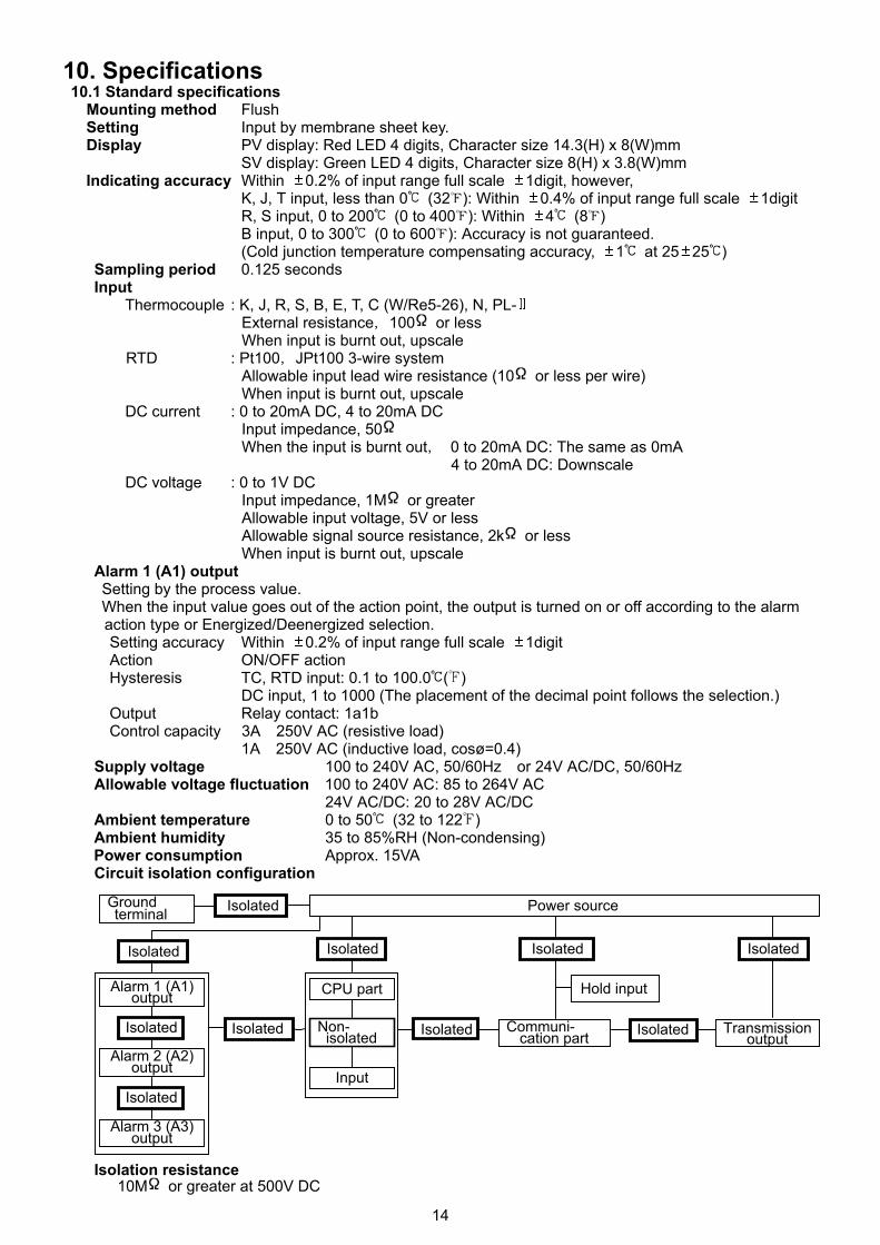
10. Specifications 10.1 Standard specifications Mounting method Flush Setting Input by membrane sheet key. Display PV display: Red LED 4 digits, Character size 14.3(H) x 8(W)mm
SV display: Green LED 4 digits, Character size 8(H) x 3.8(W)mm Indicating accuracy Within 0.2% of input range full scale 1digit, however, K, J, T input, less than 0 (32 ): Within 0.4% of input range full scale 1digit R, S input, 0 to 200 (0 to 400 ): Within 4 (8 ) B input, 0 to 300 (0 to 600 ): Accuracy is not guaranteed. (Cold junction temperature compensating accuracy, 1 at 25 25 )
Sampling period 0.125 seconds Input
Thermocouple : K, J, R, S, B, E, T, C (W/Re5-26), N, PL- External resistance,100 or less When input is burnt out, upscale RTD : Pt100,JPt100 3-wire system Allowable input lead wire resistance (10 or less per wire) When input is burnt out, upscale DC current : 0 to 20mA DC, 4 to 20mA DC Input impedance, 50 When the input is burnt out, 0 to 20mA DC: The same as 0mA 4 to 20mA DC: Downscale DC voltage : 0 to 1V DC Input impedance, 1M or greater Allowable input voltage, 5V or less Allowable signal source resistance, 2k or less When input is burnt out, upscale
Alarm 1 (A1) output Setting by the process value. When the input value goes out of the action point, the output is turned on or off according to the alarm
action type or Energized/Deenergized selection. Setting accuracy Within 0.2% of input range full scale 1digit Action ON/OFF action
Hysteresis TC, RTD input: 0.1 to 100.0 ( ) DC input, 1 to 1000 (The placement of the decimal point follows the selection.)
Output Relay contact: 1a1b Control capacity 3A 250V AC (resistive load)
1A 250V AC (inductive load, cosø=0.4) Supply voltage 100 to 240V AC, 50/60Hz or 24V AC/DC, 50/60Hz Allowable voltage fluctuation 100 to 240V AC: 85 to 264V AC
24V AC/DC: 20 to 28V AC/DC Ambient temperature 0 to 50 (32 to 122 ) Ambient humidity 35 to 85%RH (Non-condensing) Power consumption Approx. 15VA
Circuit isolation configuration
Isolation resistance 10M or greater at 500V DC
CPU partAlarm 1 (A1)output
Input
Power source
Isolated
Alarm 2 (A2)output
Alarm 3 (A3)output
Transmissionoutput
Non-isolated
Communi-cation part
Isolated
Isolated Isolated
Isolated
Isolated
Isolated
Isolated
Isolated
Hold input
Isolated
Groundterminal
15
Dielectric strength Between input terminal and ground terminal ------ 1.5kV AC for 1 minute Between input terminal and power terminal ------- 1.5kV AC for 1 minute Between power terminal and ground terminal ---- 1.5kV AC for 1 minute Between output terminal and ground terminal ----- 1.5kV AC for 1 minute Between output terminal and power terminal ------·1.5kV AC for 1 minute Output terminal: Alarm (A1, A2, A3) output terminals, transmission output terminals, communication terminals
Weight Approx. 350g External dimension 96(W) x 48(H) x 100(D)mm Material Panel and case: Flame resistant resin
Color Panel and case: Light gray Attached functions Setting value lock, sensor correction, multi-range, multi-function, power failure countermeasure, self-diagnosis, automatic cold junction temperature compensation, overscale, warm-up display, Hold function.
Accessories Mounting bracket (standard, 1 set), Instruction manual (1 copy), Unit nameplate (1 sheet) Terminal cover (1 piece, when option TC is applied),
Screw type mounting bracket (1 set, when option BL is applied)
10.2 Optional specifications Alarm 2 (A2) output (Option code: A2), Alarm 3 (A3) output (Option code: A3)
Setting by the process value. When the input value goes out of the action point, the output is turned on or off according to the alarm
action type or Energized/Deenergized selection. The option A2 and option P24 cannot be applied together.
Setting accuracy Within 0.2% of input range full scale 1digit Action ON/OFF action
Hysteresis TC, RTD input, 0.1 to 100.0 ( ) DC input, 1 to 1000 (The placement of the decimal point follows the selection.) Output Relay contact: 1a
Control capacity 3A 250V AC (resistive load) 1A 250V AC (inductive load, cosø=0.4)
Transmission output (Option code: TA, TV) Converting the input value to analog signal every 0.125 seconds, the value is outputted in current or voltage. Resolution 1/10000 DC current (TA) 4 to 20mA DC (Load resistance, maximum 500 ) DC voltage (TV) 0 to 1V DC (Load resistance, minimum 100k ) Output accuracy Within 0.3% of full scale Serial communication (Option code: C, C5) The following can be operated from the external computer. (1) Reading and setting of all values (2) Reading the input value and action status (3) Function change Communication line Based on EIA RS-485 (Option code: C5) Based on EIA RS-232C (Option code: C) Number of units connected RS-232C: 1 unit (Parallel connection is impossible.) RS-485: Maximum 31 units of FIR-201-M Communication method Half-duplex communication start-stop synchronous Communication speed 2400, 4800, 9600, 19200bps (Selectable by keypad operation) Data format Start bit : 1 Data bit : 7 Parity : Even parity Stop bit : 1
Isolated power output (Option code: P24) 24V DC of Isolated power output is provided if this option is applied. This option and option A2 cannot be applied together. Output: 24 3V DC, maximum load current: 30mA, Ripple voltage: Within 200mV
Color (Option code: BK) Front panel: Dark gray Case : Black
Screw type mounting bracket (Option code: BL) Panel thickness 1 to 15mm
16
Dust-proof・Drip-proof (Option code: IP) Dust-proof・Drip-proof specification (IP54) Effective only for panel surface (Case part is excluded.) To protect the indicator from water leak between control panel and indicator, make notes of the following. (1) Use a screw type mounting bracket. (2) The panel cutout dimension should be proper and have no burrs. (3) The control panel surface to be mounted should be vertical. The front cover (soft type, sold separately) is recommended to strengthen the Dust-proof and Drip-proof specification.
Terminal cover (Option code: TC) Electrical shock protection terminal cover
Designated specifications (1) Input, scale range: Shipped as designated range (2) Alarm action: Shipped as designated alarm action
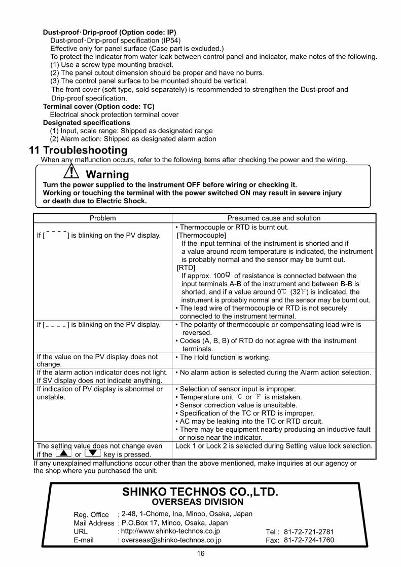
11 Troubleshooting When any malfunction occurs, refer to the following items after checking the power and the wiring.
Warning Turn the power supplied to the instrument OFF before wiring or checking it. Working or touching the terminal with the power switched ON may result in severe injury or death due to Electric Shock.
Problem Presumed cause and solution
If [ ] is blinking on the PV display.
• Thermocouple or RTD is burnt out. [Thermocouple]
If the input terminal of the instrument is shorted and if a value around room temperature is indicated, the instrument is probably normal and the sensor may be burnt out.
[RTD] If approx. 100 of resistance is connected between the input terminals A-B of the instrument and between B-B is shorted, and if a value around 0 (32 ) is indicated, the instrument is probably normal and the sensor may be burnt out.
• The lead wire of thermocouple or RTD is not securely connected to the instrument terminal.
If [ ] is blinking on the PV display. • The polarity of thermocouple or compensating lead wire is reversed.
• Codes (A, B, B) of RTD do not agree with the instrument terminals.
If the value on the PV display does not change.
• The Hold function is working.
If the alarm action indicator does not light. If SV display does not indicate anything.
• No alarm action is selected during the Alarm action selection.
If indication of PV display is abnormal or unstable.
• Selection of sensor input is improper. • Temperature unit or is mistaken. • Sensor correction value is unsuitable. • Specification of the TC or RTD is improper. • AC may be leaking into the TC or RTD circuit. • There may be equipment nearby producing an inductive fault or noise near the indicator.
The setting value does not change even if the or key is pressed.
Lock 1 or Lock 2 is selected during Setting value lock selection.
If any unexplained malfunctions occur other than the above mentioned, make inquiries at our agency or the shop where you purchased the unit.
SHINKO TECHNOS CO.,LTD.OVERSEAS DIVISION
::::
Reg. OfficeMail AddressURLE-mail
2-48, 1-Chome, Ina, Minoo, Osaka, JapanP.O.Box 17, Minoo, Osaka, Japanhttp://[email protected]
Tel :Fax:
81-72-721-278181-72-724-1760