Embed Size (px)
Citation preview
Instruction manual
11042012-EMU_GE_970315532_ENG
Marine generating setQMS 16MQMS 21TQLS 22T
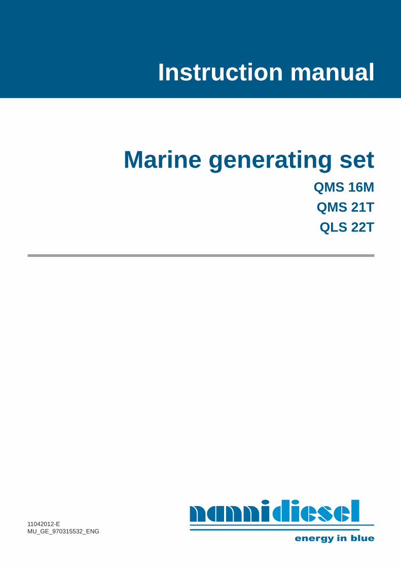
Contents
2
Safety precautions ...................................................................................................................3Presentation ..............................................................................................................................6
Fuel supply ......................................................................................................................................6Environmental responsibility............................................................................................................6Spare parts ......................................................................................................................................6Identification numbers .....................................................................................................................7About the generator.........................................................................................................................7Checks before commissioning ........................................................................................................7
Principal parts of the generating set .....................................................................................................8Instrument panel ...................................................................................................................................10
Technical characteristics .........................................................................................................11Operation of the generating set ..............................................................................................12
Before starting ......................................................................................................................................12Starting the generating set ...................................................................................................................12During operation ...................................................................................................................................13Stopping the generating set ................................................................................................................13
Maintenance ..............................................................................................................................14Daily checks .........................................................................................................................................15Air fi lter .................................................................................................................................................15Fuel system ..........................................................................................................................................16
Bleeding the fuel circuit ...................................................................................................................16Replacing the fuel fi lter ....................................................................................................................16Replacing the fuel prefi lter...............................................................................................................16Draining the water from the fuel prefi lter .........................................................................................16
Lubrication system ...............................................................................................................................17Checking the oil level ......................................................................................................................17Draining the engine oil.....................................................................................................................17Replacing the oil fi lter cartridge .......................................................................................................17
Cooling system - Coolant .....................................................................................................................18Draining and rinsing the cooling circuit............................................................................................18Coolant fi lling ...................................................................................................................................18
Cooling system - Seawater ..................................................................................................................19Cleaning the seawater fi lter .............................................................................................................19Draining and rinsing the seawater circuit ........................................................................................19Replacing the seawater pump rotor ................................................................................................19
Engine electrical system .......................................................................................................................20Alternator belt ..................................................................................................................................20Check the electrolyte level ..............................................................................................................20
Generating set storage procedure ........................................................................................................20Installation recommendations.................................................................................................21Troubleshooting .......................................................................................................................22
3
Read this chapter carefully as it concerns your safety. Most accidents are caused by failing to follow basic safety rules. Be aware of the possible risks involved in handling your generating set and make sure you take the necessary precautions to protect yourself, those around you and your equipment.
This manual contains important safety indications and information.
They are as follows:
I Warning! : This symbol indicates the risk of acci-dents and serious personal injury, substantial property damage or serious mechanical faults if the instructions are not followed.
I Caution! : Indicates a risk of personal injury and/or property damage when handling a component.
Notice: Indicates that important information must be known in order to facilitate handling or in particular cas-es.
Using and handling a generating set entails risks that could prove to be extremely dangerous. Some work re-quires specifi c knowledge and equipment. This work should be carried out by Nanni Diesel authorised per-sonnel or by a professional. If you have to work on the generating set, carefully follow the safety instructions set down in this manual.
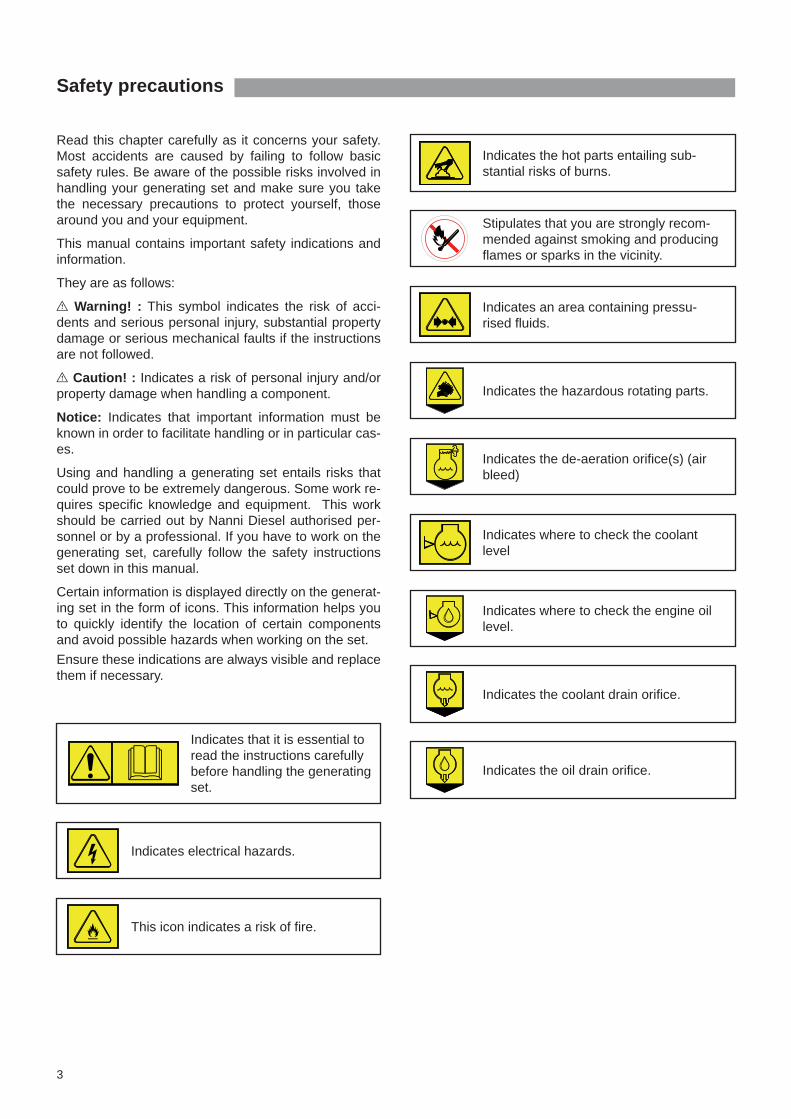
Certain information is displayed directly on the generat-ing set in the form of icons. This information helps you to quickly identify the location of certain components and avoid possible hazards when working on the set.Ensure these indications are always visible and replace them if necessary.
Indicates that it is essential to read the instructions carefully before handling the generating set.
Indicates electrical hazards.
This icon indicates a risk of fi re.
Stipulates that you are strongly recom-mended against smoking and producing fl ames or sparks in the vicinity.
Indicates an area containing pressu-rised fl uids.
Indicates the hazardous rotating parts.
Indicates the de-aeration orifi ce(s) (air bleed)
Indicates where to check the coolant level
Indicates where to check the engine oil level.
Indicates the coolant drain orifi ce.
Indicates the oil drain orifi ce.
Safety precautions
Indicates the hot parts entailing sub-stantial risks of burns.
I Exhaust gasExhaust gases contain carbon monoxide. This colour-less and odourless gas is extremely harmful and could lead to poisoning which could result in loss of conscious-ness or death. The fi rst symptoms of carbon monoxide intoxication are as follows:• Dizziness• Nausea• Headache• Throbbing temples• Vomiting• Fatigue and falling asleep• Tense musclesIf you or anyone else in the vicinity of the generating set experiences any of these symptoms, leave the area of operation of the generating set and fi nd fresh air. If the symptoms persist, consult a doctor and have your gen-erating set checked.
I Risk of electric shockNever touch the electrical connectors when the gener-ating set is operational. The voltage at the connector terminals can be lethal.Do not work on the generating set without protection: protective goggles and gloves, insulating blankets etc.Always disconnect the generating set and cut the cur-rent before working on the electrical system. Isolate the shore power supply to all the electrical circuit equip-ment.Ensure your clothing and skin is not damp or sweaty when handling electrical equipment. Remove watch-es, bracelets and jewellery when working on electrical equipment.Handling a capacitor that is still charged can be danger-ous and cause electrocution.
I Risk of burnsNever touch the hot parts of the generating set or the exhaust circuit. An operational generating set gets very hot: the exhaust elbow and pipe, turbocompressor, starter, oil sump, oil, coolant in the hoses and pipes are hot and can burn. Always check the coolant level before starting the gen-erating set.Fluids ejected under pressure can cause serious injury. Release all the pressure in the circuits before removing the caps. Never open the coolant and oil circuit caps when the generating set is operational and/or hot. Never start or run the generating set when the oil fi ll cap is not screwed on as hot oil could spray out.
If you come into contact with any of these fl uids, consult a doctor immediately. If the generating set gets too hot, switch it off and dis-connect it and wait for it to cool down before handling.
I Risk of fi reDo not smoke near the generating set and keep it away from sources of ignition (fl ames or sparks) or any other potential fl ammable vapour or liquid sources. Do not run the generating set without an air fi lter. Do not run the generating set in an area in which fl am-mable or explosive materials are stored or where gas is present. Ensure there are no fl ammable liquids in the engine compartment.Immediately clean up any liquids spilled over yourself or the fl oor and keep the engine compartment clean and accessible so as to minimise the risk of fi re. Be careful as fuel can burn.
I Risk of explosionExplosions caused by fuel vapour can cause serious injury! Carefully follow the safety rules when fi lling the fuel. Open and ventilate the storage area of the generating set after fi lling. Check that there are no fuel vapours or leaks before starting the fan (if fi tted). Switch the fan on for 5 minutes before starting the generating set.All fuel vapours are fl ammable and explosive. Be care-ful when handling and storing fuel. Store the fuel in a ventilated area away from sources of ignition (sparks or fl ames) and out of the reach of children.Stop the generating set before fi lling with fuel or lubri-cant. Do not smoke near the generating set and keep it away from sources of ignition (fl ames) when fi lling with fuel and/or lubricant. Wear gloves when investigating possible leaks. Do not alter or damage the fuel circuit. Close the fuel circuit whenever you work on it.Ensure you always have an appropriate working extin-guisher to hand.
Safety precautions
4

I Accidental startingAccidental starting can cause serious injury and even death! Disconnect the battery before working on the generat-ing set. Ensure no one is alongside the generating set or work-ing on the set before starting it. Ensure all the protection mechanisms are in place be-fore starting the generating set.
I Risk of battery explosionA battery explosion can cause serious injury and even death!Do not smoke near the batteries and keep them away from sources of ignition (fl ames or sparks). They pro-duce hydrogen which could ignite or explode on contact with an electrical arc or a fl ame. Switch off all electrical appliances in the vicinity when you are working on the batteries. Ensure the battery storage compartment is corrected ventilated.Avoid touching the battery terminals with metal tools so that no sparks are created which could cause an ex-plosion. Remove your rings, bracelets and necklaces before handing the batteries.
I Battery acidThe acid in batteries can cause serious injury and even death!When servicing the batteries, wear protective gloves and goggles. Batteries contain sulphuric acid which is highly corrosive. Acid can spurt from batteries when they are handled. If the acid comes into contact with the skin, rinse thor-oughly in fresh water and consult a doctor.
I Exhaust gasEnsure the exhaust circuit correctly expels the gas pro-duced by the generating set. Regularly check that the exhaust circuit is free of leaks and that the exhaust elbow is correctly affi xed.Operate the generating set in a well aerated and ven-tilated area away from other people. Run the fan when the generating set is operational.
I Rotating partsRotating parts can be extremely dangerous and cause serious injury and even death! Do not work on the generating set when it is operational. If work on the engine when running is absolutely neces-sary, do not touch any hot or rotating parts. Baggy clothing, hair or objects could be pulled in and/or caught and cause serious injury or substantial property damage.
Do not wear bracelets, necklaces or rings when working on a generating set.Check that the bolts and screws are properly tightened and that the protection mechanisms are in place.Do not check the fl uid levels or tension of the alternator belt when the generating set is operational.
I Lifting the generating setTo lift the generating set, use the hoisting eyes on the appliance. Always check the robustness and overall condition of the lifting equipment. Use suitable gear (cables, beams, machines, etc.) to lift your generating set. Check that your gear is capable of lifting the set. Lifting cables and chains must be able to move parallel to each other. Do not forget that any additional equipment mounted on the generating set could alter its centre of gravity. When lifting the set, it should remain as parallel as possible to the ground.
I Maintenance and spare partsNanni Diesel engines are designed to meet the different emission standards while delivering maximum service life and reliability. Regularly servicing and replacing parts with original Nanni Diesel parts will ensure the generating set con-tinues to function optimally. These parts can be ordered from all Nanni Diesel deal-ers throughout the world.
I Chemical productsThe different fl uids used to run the generating set are a health hazard. Carefully read the instructions on the packaging of these products and always check that the ventilation in the hold space is adequate.
5
Safety precautions

6
Presentation
Thank you for choosing a Nanni Diesel generating set!
Contact a Nanni Diesel authorised dealer for the servic-ing of your equipment. A list of dealers can be found on our web site:
www.nannidiesel.com
Nanni Diesel generating sets are the product of many years of experience in the development of marine en-gines and equipment designed for use in open seas.
Before using, ensure you have the correct manual for your set. We will explain how to identify your equipment and its principal specifi cations in the chapters to follow. If you don’t have the correct manual, please contact your Nanni Diesel authorised dealer.
Carefully read all of this generating set instruction man-ual and the generator documentation before starting it.
Pay particular attention to the information on personal safety. This manual must always be to hand where the generating set is used.
We recommend that you visually check the overall con-dition of your generating set before and after using it each time so that you familiarise yourself with the dif-ferent components and can more easily detect any fuel, oil or coolant leaks or abnormal wearing of the principal parts.
All the information and specifi cations in this manual are based on the technical data applicable at the time of its publication. Changes and updates may be made by Nanni Diesel without notice.
Certain images, diagrams or equipment described in this manual may not exactly represent (or be part of) your generating set order.
Fuel supplyEnsure that the fuel contains no residues. If it does, use special fi lters.
Avoid using fuel mixed with water or other substances as you may damage the engine.
The engine performance is infl uenced by the fuel tem-perature, the temperature and relative humidity of the exhaust air and by the altitude.
Environmental responsibilityNanni Diesel designs its engines to have minimum en-vironmental impact and a maximum service life. This objective, however, can only be achieved with your full cooperation. Our operating and maintenance instruc-tions are to help you to protect your generating set and adopt responsible behaviour vis-to-vis the environment.
Observe the warning and caution labels affi xed to the generating set.
Ensure you only use the fuels and oils recommended in this manual. Using another type of fuel or oil could cause major generator malfunctions: higher consump-tion, reduced engine service life, greater discharge of exhaust gases.
When draining the oil and changing the oil or fuel fi l-ter, dispose of the waste in the appropriate container. These fl uids cause major damage to fl ora and fauna if discharged into nature.
The different fl uids used to run the engine are a health hazard. Carefully read the instructions on the packaging of these products and always check that the ventilation in the storage compartment is adequate.
Spare partsYou can order the emergency parts below from any Nanni Diesel authorised dealer. Keep a copy of the list of parts with the set.
These emergency parts could allow you to repair your engine in the event of a fault.
• V-belt
• Seawater pump rotor kit
• Engine oil fi lter
• Fuel fi lter (fi ltering part)
• Injection tube
• Glow plug
• Air fi lter
• Nanni Diesel blue paint
Certain items may vary depending on your order. Con-tact your authorised dealer for more information.

7
• The TYP inscription indicates the commercial des-ignation of the generating set (eg. QMS10T).
• The NR inscription indicates the engine serial number.
• The CODE inscription lists the various specifi ca-tions of your engine.
The elements on the alternator identifi cation plate are explained in the alternator documentation.
About the generator Refer to your generator manual for more information about this component.
The generators are installed and run for the fi rst time in our factory. A professional electrician should connect the generating set to the craft’s electrical circuit follow-ing the applicable safety standards.
Always check the installation of your generating set be-fore handling it. Check the overall condition of the gen-erator, the tightness of the assembly screws and the stability of the generator as a whole.
TYP
NR
CODE
Identification numbersYour generating set has 2 identifi cation plates: one for the engine and one for the generator.
Keep these plates accessible and in good condition. Record and keep the engine and generator serial number and designation. These numbers will be useful if you work on your set, order parts or invoke the war-ranty.
The engine identifi cation plate is as follows:
Checks before commissioningI Caution! : Your generating set must be installed by a shipyard or authorised representative following the on-board assembly instructions.
The electrical connections must also be carried out by qualifi ed personnel. The electrical installation must be equipped with all the mechanisms for protecting people and property in accordance with the applicable stand-ards.
When the set has been installed on board and before removing the protective elements covering the different orifi ces, clean the exterior surface of the generating set.
For transportation reasons, some of our generating sets are delivered without their operating fl uids. In all cases, you must:
• Check the levels and fi ll the engine oil if necessary.
• Fill the exchanger with coolant and degas if neces-sary.
• If necessary prime the raw water circuit
• Check the belt tension.
• Check the tightness of the different connections and drain caps (coolant and oil).
• Check the tightness of the alternator electrical lugs (check the cabling by referring to the corresponding documentation), battery terminals, circuit breaker, connection of extension sections, battery electro-lyte level.
• Make a fi nal check of the fi xing elements and a vis-ual check of the generating set as a whole.
Some of these operations are explained in more detail later in this manual.
I Caution! : The modern fuel engine is precision equipment that requires the use of a high-quality fuel and lubricant.
Presentation
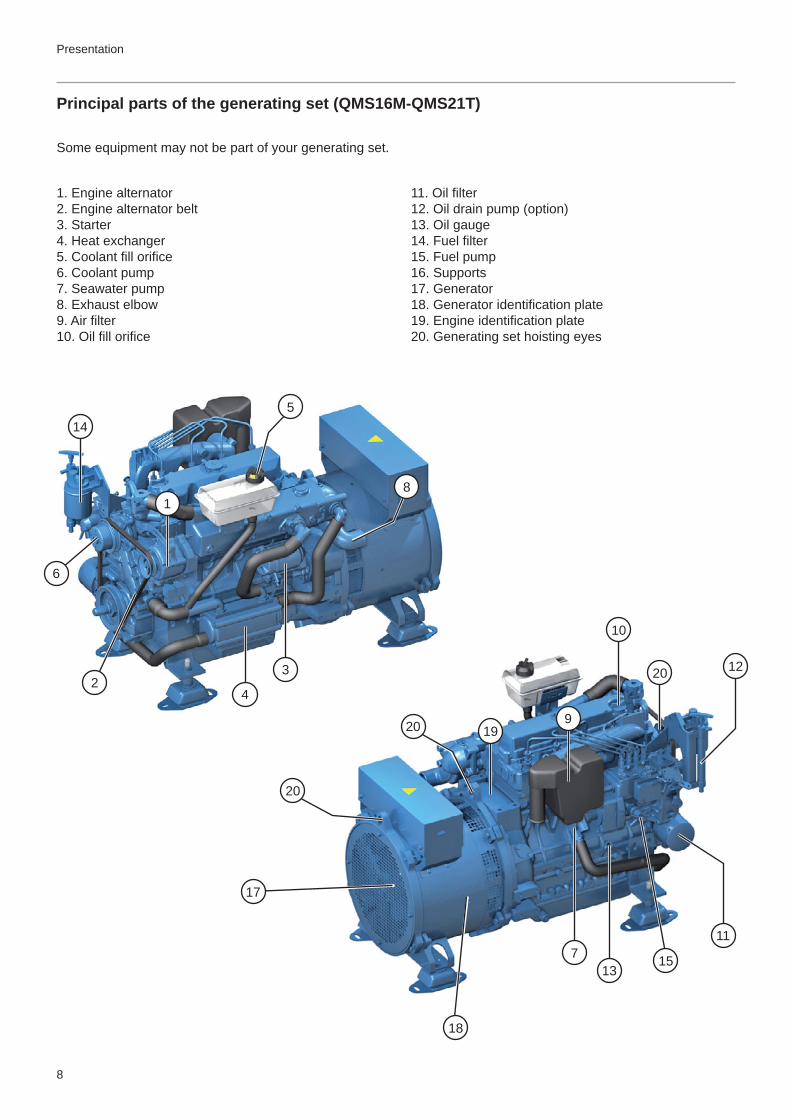
1. Engine alternator2. Engine alternator belt3. Starter4. Heat exchanger5. Coolant fi ll orifi ce6. Coolant pump7. Seawater pump8. Exhaust elbow9. Air fi lter10. Oil fi ll orifi ce
11. Oil fi lter12. Oil drain pump (option)13. Oil gauge14. Fuel fi lter15. Fuel pump16. Supports17. Generator 18. Generator identifi cation plate19. Engine identifi cation plate20. Generating set hoisting eyes
Principal parts of the generating set (QMS16M-QMS21T)
Presentation
8
Some equipment may not be part of your generating set.
5
1
11
10
23
4
6
7
8
9
12
13
14
15
17
1920
20
20
18

Presentation
Principal parts of the generating set (QLS22T)
9
1. Engine alternator2. Engine alternator belt3. Starter4. Heat exchanger5. Coolant fi ll orifi ce6. Coolant pump7. Seawater pump8. Exhaust elbow9. Air fi lter10. Oil fi ll orifi ce
11. Oil fi lter12. Oil drain pump (option)13. Oil gauge14. Fuel fi lter15. Fuel pump16. Supports17. Generator 18. Generator identifi cation plate19. Engine identifi cation plate20. Generating set hoisting eyes
Certain equipment may not be part of your generating set.
5
1
11
10
23
4
6
7
8
9
12
13
14
15
17
1920
20
18

!
STOP
ON / STOP STARTSTOP
ON / STOP START
! °C
40
6080 100
120
°F
105
180 220
250
bar
0
1 2 34
50
20 4060
80
psi
The instrument panel allows you to start and stop the generating set, and provides you with important information when the generating set is under operation. Check this informations regularly while operating the generating set. Contact an authorized Nanni Diesel dealer if your generating set is equipped with instruments different than those described in this chapter.
I Caution! : On a soundproof generating set, the local/remote selector must be in remote position to start the generating set using the instrument panel.
I Caution! : If the coolant temperature rises or the oil pressure falls abnormally, the corresponding indicators will illuminate and the generating set will stop automatically.
1. Heating. This indicator illuminates when the glow plugs are heating the combustion chambers (if fi tted on your generating set).
2. Coolant temperature. This indicator illuminates and an audible alarm sounds if the coolant in the cooling circuit overheats.
3. Battery charge. This indicator illuminates when the set is switched on. If it lights when the generating set is running, this indicates an engine alternator charging fault.
4. Oil pressure. This indicator illuminates and an au-dible alarm sounds if the oil pressure in the lubrication circuit falls.
5. Indicator showing presence of water in fuel fi lter (if fi tted). This indicator illuminates when there is too much water in the fuel fi lter.
6. On indicator. This indicator shows that the generat-ing set is powered (ignition).
7. Start/Stop buttons. This component starts and stops the generating set. The ON/STOP button switch powers up and stops the engine. The START button starts the genset.
8. Engine oil pressure Caution! This indicator does not show the engine oil level. This indicator shows the oil pressure. An audible alarm sounds and the generat-ing set stops if the oil pressure in the lubrication circuit falls.
9. Coolant temperature. Indicates the coolant tem-perature. An audible alarm sounds and the generating set stops if the coolant in the cooling circuit overheats.
3
6
24
5
1
Instrument panel
10
Tableau Luxe GE Tableau Eco GE
8 9
7
3
6
2 4
51
7
Presentation
11
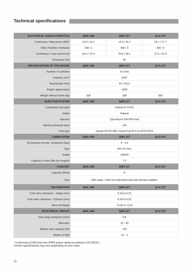
Technical specifications
* Continuous (COP) and max (PRP) power rating according to ISO 8528-1Certain specifi cations may vary depending on your order.
ELECTRICAL CHARACTERISTICS QMS 16M QMS 21T QLS 22T
Continuous / Max power (kW)* 13.9 / 16.2 14.3 / 16.7 15.1 / 17.7
Volts / Number of phases 230 / 1 400 / 3 400 / 3
Continuous / maxi current (A) 60.4 / 70.4 25.8 / 30.1 27.2 / 31.9
Frequency (hz) 50
SPECIFICATIONS OF THE ENGINE QMS 16M QMS 21T QLS 22T
Number of cylinders 4 in line
Capacity (cm3) 2197
Bore/stroke (mm) 87 x 92,4
Engine speed (rpm) 1500
Weight without frame (kg) 328 328 360
INJECTION SYSTEM QMS 16M QMS 21T QLS 22T
Combustion principle Indirect E-TVCS
Intake Natural
Injectors Type Bosch DN-0PD mini
Injection pressure (bar) 140
Fuel type Gazole NF-EN 590 / Diesel Fuel N°2-D ASTM D975
LUBRICATION QMS 16M QMS 21T QLS 22T
Oil pressure at max. revolutions (bar) 3 - 4.5
Type API-CF mini.
Grade 15W40
Capacity in litres (fl at four engine) 7.5
COOLANT QMS 16M QMS 21T QLS 22T
Capacity (litres) 9
Type 50% water + 50% mix anti-freeze and anti-corrosion additive
DISTRIBUTION QMS 16M QMS 21T QLS 22T
Cold valve clearance - Intake (mm) 0,18 to 0,22
Cold valve clearance - Exhaust (mm) 0,18 to 0,22
Valve shrinkage +0,05 to -0,15
ELECTRICAL CIRCUIT QMS 16M QMS 21T QLS 22T
Glow plug resistance (ohm) 0.8
Alternator 12 - 40
Battery mini capacity (Ah) 120
Starter (V-kW) 12 - 1
12
Operation of the generating set
Before starting
I Caution! : Before starting, ensure that the seacock is open as the seawater pump rotor can be damaged if run dry for just a few seconds. Generating sets with a Keel Cooling system are not fi tted with a seawater pump.
Never use a starting aerosol or any other equivalent product. These products are highly fl ammable.
Before starting the engine and before the set is used each time:
• Check the fuel level
• Open the fuel shutoff valve
• Open the seacock (if fi tted)
• Check the engine oil level and fi ll with the recom-mended oil if necessary. See the “Maintenance” section for more information.
• Check the coolant level and fi ll with the recom-mended coolant if necessary. See the “Mainte-nance” section for more information.
• Open the hold space panel(s) to fully ventilate the hold space if it is not equipped with a fan. Otherwise run the fan in the hold space for 5 minutes.
• Close the battery switch (ON position) and check that the emergency stop is not activated.
I Caution! : Ensure you have replaced the protection elements before starting the generating set.
Notice: If your engine has not been used for several months of if the fuel circuit has been drained, use the priming pump situated above the fuel fi lter. This fi lls the fuel circuit if it has drained out or after a circuit compo-nent has been replaced.
Starting the generating setI Caution! : On a soundproof generating set, the lo-cal/remote selector must be in remote position to start the generating set using the instrument panel.
Carry out the following operations to start your generat-ing set in complete safety:
1. Press the ON/STOP button. All of the indicators illuminate and an audible signal sounds. This stage allows you to check that these elements are working properly. After a few moments, only the oil and battery charge indicators will remain lit.
2. Hold the START button at midcourse to begin preheating. The PREHEAT warning light illuminates. Hold the button for 5 to 20 seconds according to the temperature on the outside. Push fully the button to start the generating set.
I Caution! : If the generating set does not start on the fi rst attempt, repeat the manoeuvre, waiting 5 to 15 seconds between each attempt, with the set switched off. Never force it as there is a risk of water backfl ow into the engine via the exhaust system.
Check the indicators on the instrument panel after start-ing and when operating the set.
Check also that the seawater is running through the ex-haust and check there are no fuel or water leaks.
I Caution! : If the coolant temperature rises or the oil pressure falls abnormally, the corresponding indicators will illuminate and the generating set will stop auto-matically.
Identify and eliminate the cause before restarting the engine. See the “Fault-fi nding” section for more infor-mation.

13
Operation of the generating set
During operation Regularly check the indicators on the generating set in-strument panel.
Notice: If the generating set runs continuously, the oil level should be checked every 8 hours.
Never press the START button when the generating set is under operation.
Alarm indicatorsIf the oil pressure is too low in the engine lubrication cir-cuit, the “engine oil pressure” indicator illuminates and an audible alarm sounds and the generating set stops.
If the coolant temperature is too high, the “coolant tem-perature” indicator illuminates and an audible alarm sounds and the generating set stops.
I Warning! : Never open the coolant and oil circuit caps when the engine is running and/or hot.
If the voltage supplied by the engine alternator drops, the “Battery charge” indicator illuminates.
See the “Fault-fi nding” section for the basic checks to make in the event of a fault.
In all cases, if one or more of these problems persist, stop your generating set except in emergencies and contact your Nanni Diesel authorised dealer.
Stopping the generating set Before stopping the generating set, cut the power of the electrical appliances connected to the craft’s on-board electrical circuit.
Depress the ON/STOP button and then release.
Emergency stop
You can stop the engine manually if the standard shut-down procedure is not working or in an emergency. Use the emergency stop button situated on the electrical junction box or cut the fuel supply.
I Warning! : Working on a running motor is extremely dangerous.
After the engine has stopped
Open the circuit breaker (battery supply closed), close the seacock (if fi tted) and the fuel shutoff valve. Check the condition of the compartment in order to identify any leaks.
I Warning! : Even after your generating set has stopped, elements remain hot and pressurised for sev-eral minutes. As far as possible, limit work on the gen-erating set immediately after stopping it.
I Caution! : If your generating set is connected to a seawater intake, if the craft is being towed, stop the generating set and always close the seacock to prevent the generating set from accidentally fi lling with seawa-ter.
14
The regular maintenance of your generating set is essential for ensuring optimal reliability and service life. The following operations and the those described in the Silverwake warranty booklet will enable you to extend the service life of your engine and reduce its impact on the environment.
During the warranty period, it is essential that all work is carried out by a Nanni Diesel authorised dealer. However, some regular checks, particularly those made each time the engine is used, can only be made by the user.
Some operations are explained to you further on so that you can work on the engine in an emergency or if there is no repair centre nearby. However, we recommend you have your work checked by a Nanni Diesel authorised dealer.
I Caution! : As far as possible, limit work on the engine when it is under operation and/or when you are sailing.
These instructions only describe a part of the maintenance operations to be carried out. Find the complete list on the Silverwake warranty booklet. The operations listed on the Silverwake must be carried out by an authorised Nanni Diesel technician.
The instrument panel shows you how long your engine has run since its commissioning.
Notice: Some equipments are optional and may not be part of your generating set.
In order to preserve the mechanical qualities of the engine and prolong its service life, we recommend you follow the instructions below:
Use a coolant made of 50% water and 50% of pure antifreeze. Use clean and distilled water for the mix: Water that is too hard will produce limescale build-up and will reduce the cooling system’s effectiveness.
The cooling system allow the engine to operate at a optimal temperature. The cooling system must be filled with a coolant that protects the engine against internal corrosion and from freezing, if the climate requires it. A faulty operation of the cooling system reduces its efficiency and therefore the engine’s service life.
Use antifreeze depending on climatic conditions: it will protect against freezing to a temperature of less than -25°C. If the engine must be switched off for a long period in an environment with a high risk of frost, the coolant must be drained.
Do not engage the starter motor for more than 10 seconds: The continuous use of the starter for more than 10 seconds will damage the system.
Choose a diesel fuel meeting standard DIN-EN 590. If using Biodiesel (according to UNI EN14214 specifications) this can be blended up to 5% with a fuel available in Europe (according to the DIN EN 590 standard: a lower quality fuel will result in poor combustion, which may cause starting problems and heavy smoke emissions.
Draining the fuel tank: Remove the deposits in the fuel regularly. The fi rst time after 50 hours of operation and then every 300 hours.
Use a good-quality lubricant: Poor-quality lubricating oil will damage the engine in terms of the wear of the parts, jamming, etc., or rather reduce its service life. Use an API-CF mini type oil adapted to the climatic conditions and temperature (Contact your local dealer for further informations).
Maintenance
15
Regularly check the condition of the generating set and its compartment before and after it is used: check for the presence or not of fuel or oil leaks, the tightness of the different clamps and bolts, the condition of the belts, hoses and the various electrical cables, the wear of the zinc anode (if fi tted), the battery electrolyte level.
These relatively simple checks can help you to detect possible faults before major work on your set is required.
I Caution! : Do not let oil, fuel or grease deposits build up around the generating set as they may increase the risk of fi re in the engine compartment.
Check the operation of the different lamps and indica-tors situated on the instrument panel. Take care not to get the generator wet when cleaning the engine.
Maintenance
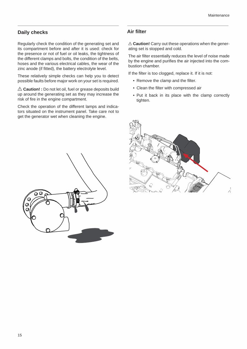
I Caution! Carry out these operations when the gener-ating set is stopped and cold.
The air fi lter essentially reduces the level of noise made by the engine and purifi es the air injected into the com-bustion chamber.
If the fi lter is too clogged, replace it. If it is not:
• Remove the clamp and the fi lter.
• Clean the fi lter with compressed air
• Put it back in its place with the clamp correctly tighten.
Daily checks Air fi lter

16
Fuel system
I Warning! : Total cleanliness must be guaranteed when working on the fuel circuit. No impurities must en-ter the injection pump and the injectors. Carry out each of these operations with the engine cold and stopped.Bleeding the fuel circuitThe fuel circuit is self-priming but manual bleeding is re-quired after replacing the fi lter, after have running out of fuel or after a work on the circuit if it has been emptied.
• Loose the drain valve screw A on the engine fuel fi lter support.
• Pump the priming pump by pressing the button B repeatedly until bubble-free fuel comes out of the drain valve screw.
• Tighten the drain valve screw and lock the hand pump.
I Caution! : Avoid draining all the fuel in the fi lter when venting. If so, remove the fi lter and replenish with fuel before replacing it and repeat the venting operations.
Maintenance
B
A
Replacing the fuel filterThis fi lter treats the water and impurities in the fuel be-fore it enters the injection circuit.
• Cut the fuel intake at the tank.
• Place a receptacle under the fi lter and then remove the used fi lter C cartridge.
• Apply a thin layer of fuel over the seal surface of the new fi lter cartridge before fi tting it.
• Tighten it by hand until the fi lter makes contact with the fi lter head then tighten it by a half-turn.
• Untighten the drain valve screw to release the air. Open the fuel valve again and drain the circuit.
• Start the engine and check the assembly is leak-tight.
I Caution! : Used fi lters must be disposed of in an ap-propriate container.
Replacing the fuel prefilter The fuel prefi lter is an optional component that purifi es the fuel before it is injected in the engine. These instruc-tions are given as an example only.
• Close the fuel shutoff valve on the fuel tank.
• Place a receptacle under the fuel prefi lter. Remove the fi lter tank
• Drain and clean the fi lter tank.
• Replace the cartridge and re-install the tank.
• Open the fuel valve. Drain the feed system then start the engine to check the leak-tightness.
Draining the water from the fuel prefilter Before starting the engine each time, ensure there is no water in the fuel prefi lter. If there is water, place a tray under the fuel prefi lter and then drain the water and impurities using the bottom cap/valve.
C

17
Lubrication system
Checking the oil level I Caution! : Carry out these operations with the engine stopped. Hot oil and hot surfaces can burn.
If oil of a different brand or viscosity to the previous is used, drain the old oil. Never mix two different types of oil. Observe the recommended draining intervals.
The oil level should be within the range indicated on the oil gauge. To check the oil level:
• Start the engine and let it run at idle for several minutes.
• Stop the engine and remove the starter key.
• Remove and wipe down the gauge rod.
• Re-insert it and then remove it.
• Check whether the oil level is between the two notches. If the level is too low, add more oil until reaching the specifi ed level.
Top up oil slowly via the fi ller port located on the top of the engine. Add the oil slowly and wait several minutes before checking the level again. This allows the oil to run into the engine crankcase.
I Caution! : Do not fi ll the crankcase above the maximum level indicated on the gauge.
Draining the engine oilI Warning! : Carry out these operations with the engine stopped. Hot oil and hot surfaces can burn.
• Start the engine and let it warm up for approximately 5 minutes so that oil suction is easier. Stop the engine.
• Use a pail to collect the extracted oil and pump until the oil has been completely extracted. Refi ll with the new oil (the amount of oil to add is indicated in the technical specifi cations section).
• Check the level with the gauge, ensuring you do not go above the maximum level.
• Start the engine and check that the oil pressure indicator is extinguished and that there are no leaks in the lubrication circuit. Let the engine warm up for several minutes and then check the oil level again. Fill again if necessary.
Replacing the oil filter cartridge I Caution! : Carry out these operations with the en-gine stopped. Hot oil and hot surfaces can burn.
• Remove the oil fi lter cartridge with a fi lter key.
• Clean the fi lter support in order to prevent impuri-ties from entering the engine.
• Apply a fi ne layer of oil over the rubber seal of the new cartridge.
• To install the new cartridge, tighten it by hand until it makes contact with the fi lter head and then tighten by a half-turn. Over-tightening may lead to the de-formation of the seal.
• After replacing the fi lter, check that the engine oil is not leaking through the seal and check the oil level using the gauge. Add oil if necessary.
Maintenance

18
Cooling system - Coolant
Maintenance
The cooling system enables the engine to operate at an optimal temperature. In the case of a cooling by closed heat exchanger, the coolant is cooled by sea water passing through the exchanger. Then it cooled several components of the engine.
In a Keel Cooling system, engine heat is dissipated by passing coolant through tubes incorporated to the hull. Contact the installer of the genset for more informations.
The cooling system must be fi lled with a coolant com-prising 50% water and 50% anti-freeze and anti-corro-sion additive.
The coolant must be changed regularly as the additives become less effective over time. Prepare the mix be-fore fi lling the exchanger. If the generating set must be switched off for a long period in an environment with a high risk of frost, the coolant must be drained.
I Attention! : Never use just water to fi ll the cooling circuit. Always use a clean receptacle and ensure the fl uids are well mixed.
Draining and rinsing the cooling circuit The coolant in the cooling circuit must be drained in order to remove the various deposits that can build up in the circuit.
Carry out this operation with the engine stopped and cold.
• Place a receptacle under the hose A then remove it.
• Remove the fi ll cap situated on the expansion tank in order to let the coolant fl ows faster. Let the cool-ant run out until the exchanger is empty.
• Place a receptacle under the hose B then remove it.
• Let the coolant run out.
• Clean the system with fresh water the refi t then hoses.
Coolant fi lling
I Attention! : Do not check the coolant level when the engine is hot. Pressurised coolant can spurt and cause serious burns. Carry out this work with the engine stopped and cold. Only use new coolant when replenishing or adding coolant.
The coolant level must be between the min and max level indicated on the expansion tank.
• Turn the fi ll cap A situated on the expansion tank to its fi rst stop to release the system pressure and then remove the cap.
• Open the plug B
• Fill the expansion tank slowly with coolant up to the maximum level in order to let the air escape. When the coolant fl ows from the orifi ce B, close the plug and fi ll the expansion tank to the max level if necessary.
• Run the engine for several minutes without load. Stop the engine, wait a few moments, then check the coolant level again. Fill again if necessary.
A
B
A
B

19
Cooling system - Seawater
I Caution! : When the craft is in the water, there is a risk of water penetrating the craft when working on the seawater circuit. Water can penetrate the craft via com-ponents located below the waterline. Close the seacock (if fi tted) or prevent water discharge before working on the seawater system !
Cleaning the seawater system is essential to prevent the formation of deposits and salt crystals.
Your generating set may not be fi tted with a seawater cooling system (such as in the case of a Keel Cooling system).
Cleaning the seawater filter The seawater fi lter is an optional component. These in-structions are given as an example only.
• Check the condition of the seawater fi lter with the engine stopped. If deposits have formed, remove the fi lter in order to clean it.
• Remove the cover and then the fi ltering part A. Re-move all the debris on the housing.
• Rinse the fi lter and the housing with fresh water and check the condition of the seal, then re-install all the components and check there are no water and/or air leaks in the circuit when operational.
Draining and rinsing the seawater circuit• Close the seacock.
• Disconnect the hose running from the seacock.
• Place the hose in a receptacle fi lled with fresh wa-ter. Ensure the receptacle you use is large enough as the seawater pump must never be run without water.
• Check that no one is in the vicinity of the engine and then start it. Let the engine run for several min-utes, checking that the receptacle is at all times fi lled with fresh water.
• Once the circuit is fully rinsed, re-connect the hose correctly to the seawater fi lter.
• Drain also the exhaust circuit. A small amount of water may remain in the bottom of the waterlock box.
• Run the engine for few minutes in order to check for leakage.
Replacing the seawater pump rotor The seawater pump rotor is an essential component. It must be replaced regularly along with the seal. A worn rotor could crack and damage the cooling system. Al-ways have a replacement rotor on board the craft.
• Close the seacock.
• Remove the seawater pump cap A and the seal B, then remove the rotor C without damaging it.
• Check the condition of the rotor: replace it if even the most minor defect is noted. If the rotor is dam-aged, drain the seawater system and check that the heat exchanger is not clogged by pieces of rub-ber. Clean it if necessary.
• Clean the elements.
• Fit a new rotor by turning it clockwise.
• Lubricate the pump casing and the inside of the lid with waterproof grease for rubber.
• Refi t the water pump cap using a new seal.
• Open the seacock and then start the engine to check that the circuit is leak-tight.
B
A
C
Maintenance
I Caution! : Stop the generating set and the cut the battery supply before working on the electrical circuit.
Alternator beltMake this check after running the generating set when the belt is hot.
I Caution! : Some parts of the generating set can be extremely hot.
Check the belt tension by pushing down at midpoint be-tween the drive pulley and the alternator pulley.
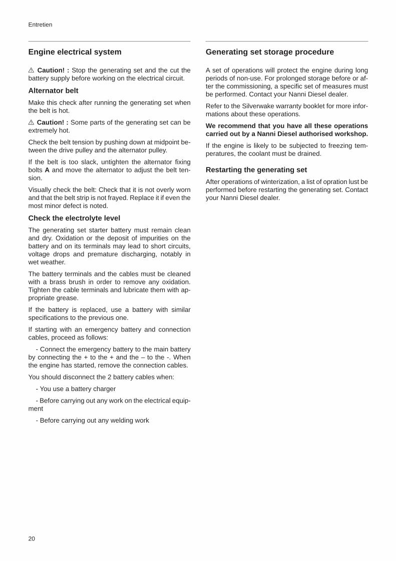
If the belt is too slack, untighten the alternator fi xing bolts A and move the alternator to adjust the belt ten-sion.
Visually check the belt: Check that it is not overly worn and that the belt strip is not frayed. Replace it if even the most minor defect is noted.
Check the electrolyte levelThe generating set starter battery must remain clean and dry. Oxidation or the deposit of impurities on the battery and on its terminals may lead to short circuits, voltage drops and premature discharging, notably in wet weather.
The battery terminals and the cables must be cleaned with a brass brush in order to remove any oxidation. Tighten the cable terminals and lubricate them with ap-propriate grease.
If the battery is replaced, use a battery with similar specifi cations to the previous one.
If starting with an emergency battery and connection cables, proceed as follows:
- Connect the emergency battery to the main battery by connecting the + to the + and the – to the -. When the engine has started, remove the connection cables.
You should disconnect the 2 battery cables when:
- You use a battery charger
- Before carrying out any work on the electrical equip-ment
- Before carrying out any welding work
20
Entretien
Engine electrical system Generating set storage procedure
A set of operations will protect the engine during long periods of non-use. For prolonged storage before or af-ter the commissioning, a specifi c set of measures must be performed. Contact your Nanni Diesel dealer.
Refer to the Silverwake warranty booklet for more infor-mations about these operations.
We recommend that you have all these operations carried out by a Nanni Diesel authorised workshop.
If the engine is likely to be subjected to freezing tem-peratures, the coolant must be drained.
Restarting the generating setAfter operations of winterization, a list of opration lust be performed before restarting the generating set. Contact your Nanni Diesel dealer.

21
The recommendations given in this chapter do not cover all the installation possibilities, but offer recom-mendations and guidelines for installing a Nanni Diesel generating set. Certain equipment may not be part of your order or installation.
InstallationThe generating set and the coupled equipment must be accessible for maintenance work. The generating set must be mounted on a rigid and solid structure on the hull that is capable of withstanding all the dynamic stresses and the weight of the set as a whole. The gen-erating set must not be inclined by more than 5° when the craft is stopped.
Avoid installing the generating set too close to walls that are too thin that could reverberate. In all cases, the gen-erating set should not be installed directly on a wood or plywood surface or in contact with walls. A solid steel support will reduce the vibrations and noise produced by the generating set.
The various cables and electrical extension sections must be securely affi xed to the generating set and/or to the compartment walls (do not let them hang in the hold).
VentilationThe temperature inside the compartment must not ex-ceed 50°C with a maximum difference of 20°C in rela-tion to the ambient temperature.
For slow craft, ventilation must be provided by a fan. Fresh air must circulate from front to back. The air in-take should be situated at the bottom front of the engine compartment and the exhaust at the top back in order to ensure optimal air circulation.
Electrical installationAn incorrect or faulty electrical installation could cause leakage currents that could affect the galvanic protec-tion of the generating set and consequently the gener-ating set itself. The installer should ensure that all the necessary precautions are taken to guarantee the cor-rosion protection of the generating set.
Fuel feed systemThe generating set must have its own fuel feed system. The tanks must be placed as far as possible at the same height as or slightly higher than the engine.
The fuel return pipe must always be situated under the minimum tank fi ll level.
The maximum height between the fuel pump and the minimum tank level is of 0.5 m. An electrical pump must be installed above this value.
Cooling systemYour generating set is cooled by a coolant passing through the different parts of the engine. It may also be fi tted with a heat exchanger cooled by seawater which, among other things, cools the coolant and the exhaust gases (except in the case of a Keel Cooling system).
In this case, the generating set must have its own sea-water cooling system with no connection to the engine system or other equipment. The seawater intake must always face the back of the craft (regardless of the type of craft) and must be as close as possible to the genset.
The height of the seawater fi lter and the exhaust outlet must be 150 mm above the waterline.
An anti-siphon must always be installed if the generat-ing set is below the waterline. It should be placed at least 500 mm and at most 2 metres above the waterline.
The waterlock box must be positioned as close to the engine and as low as possible.
The exhaust pipe situated between the waterlock and the hull outlet should form a gooseneck (as shown in the diagrams below). The highest point of the goose-neck should be at a maximum distance of 3 metres from the waterlock and at a maximum height of 1.5 metres in relation to the waterlock.
Installation recommendations

This section helps you to understand the different problems that may arise on your generating set. The safest way to correct the problems you may encounter, however, is to contact a qualifi ed engineer. Some operations must be carried out by a qualifi ed Nanni Diesel authorised engineer. These operations are marked in bold in the tables below.
This non-exhaustive list serves as a tool in emergencies and should never be considered a repair procedure. Some of the components listed may not be part of your engine.
Faults and probable causes
Engine does not start / starter does not turn
Faults Solution
Circuit breaker is open or fuse has blown Check and re-install the circuit breaker or replace the fuse or replace the circuit breaker
Electrical circuit breaker is not working
Electrical connections are faulty Check the electrical connections and wires (especially the battery cables) Clean and tighten the connections
Battery faulty Test and charge or replace the battery if faulty
Starting procedure defective Read and implement the starting procedure
Fuel tank empty or fuel cock closed Fill the tank or open the cock
Fuel pump faulty Replace the pump
Fuel fi lters clogged or water present Clean or replace the fuel fi lters or drain the water from the prefi lter then drain the circuit
Fuel contaminated or too old Drain the tank if contaminated and fi ll with clean fuel
Fuel pipe or air pipe of tank blocked or bent Replace the bent pipes or blow in compressed air to remove the obstruction
Air present in fuel injection system Drain the injection system
22
Troubleshooting

Faults and probable causes
Engine overheats / Engine coolant temperature too high
Faults Solution
Seacock is closed Open the Seacock
Seawater fi lter is clogged Close the Seacock and clean the fi lter
Seawater pump is sucking air Check the position and seal of the seawater fi lter cover and the suction hose
Fresh water circuit pump belt is slack or faulty Re-tighten or replace the belt
Seawater pump rotor is faulty Replace the rotor
Insuffi cient coolant Fill with coolant and check that the cooling system is leak-tight
Thermostat is malfunctioning Replace the thermostat
Cooling system is blocked Locate the problem and clean
Closed cooling circuit is dirty Clean and rinse
Loss of pressure in the closed cooling circuit Check there are no leaks. Clean, inspect and check the fi ll cap
Coolant is unsuitable Use the recommended coolant (see technical specifi cations)
23
Troubleshooting

Nanni Industries S.A.S. 11, Avenue Mariott e - Zone Industrielle 33260 La Teste FranceTel : + 33 (0)5 56 22 30 60 Fax : +33 (0)5 56 22 30 79E-mail : [email protected]
© 2011 - Nanni Industries S.A.S
The images, text and information contained in this document are based on the product specifi cations at the time this document was published. Nanni Diesel reserves the right to alter this document without notice.
Research programme backed by the Conseil Régional d’Aquitaine