Embed Size (px)
Citation preview

INSTRUCTION MANUAL
Trimble® ZX5 Ground Station and GeoMap Win 3.4 Software
Instruction Manual Including Waypoint Mission
Version 1.0.0
Revision A
August 2015

Legal information
Trimble Navigation Limited 935 Stewart Drive Sunnyvale, California 94085 U.S.A. www.trimble.com
Copyright and trademarks
© 2015, Trimble Navigation Limited. All rights reserved.
Trimble and the Globe and Triangle logo are trademarks of Trimble Navigation Limited, registered in the United States and in other countries.
All other trademarks are the property of their respective owners.
For a complete list of all relevant legal notices, refer to the Trimble UX5 Aerial Imaging Solution User Guide.

Contents 1 Purpose of the software ...................................................................................................... 5
2 Installation/Deinstallation .................................................................................................. 6
3 Summary ............................................................................................................................ 7
4 Menu Items ........................................................................................................................ 8
4.1 File - Cancel ............................................................................................................................. 8
4.2 Live Tools ................................................................................................................................. 8
5 Tab “Configuration” ............................................................................................................ 9
5.1 Tab settings ............................................................................................................................. 9
5.1.1 Set data link................................................................................................................ 9
5.1.2 Group Frames........................................................................................................... 10
5.1.3 Group Tele-Ctrl ......................................................................................................... 10
5.2 Tab Servo Setup ..................................................................................................................... 11
5.3 Example: adjust a servo......................................................................................................... 12
6 Tab “FlightControl” ............................................................................................................13
6.1 Status “RX” ............................................................................................................................ 13
6.2 Status “Flight mode” ............................................................................................................. 14
6.3 Status “Components” ............................................................................................................ 14
6.4 Group “Telemetry” ................................................................................................................ 15
6.5 Group “Telecontrol” .............................................................................................................. 15
6.6 Group “GPS-Mode” ............................................................................................................... 15
6.7 Group "POI-Mode" ................................................................................................................ 16
7 Tab “FlightRecorder” ..........................................................................................................17
7.1 Open ...................................................................................................................................... 17
7.2 Select Flight Record ............................................................................................................... 18
7 .2.1 Drive selection ......................................................................................................... 18
7.2.2 Get Directory ............................................................................................................ 18
7.2.3 List ............................................................................................................................ 19
7.2.4 Save .......................................................................................................................... 19
7.2.5 Read ......................................................................................................................... 19
7.2.6 File Open .................................................................................................................. 19
7.3 Open in GE ............................................................................................................................. 19
7.4 GeoReference ........................................................................................................................ 19
7.5 Display of the flight data ....................................................................................................... 20
7.6 Select the point of time ......................................................................................................... 20
8 Tab “WayPoint” .................................................................................................................21
8.1 Status indication .................................................................................................................... 21
8.2 Group “Waypoint mission” ................................................................................................... 22
8.3 Group "Direct waypoint" ....................................................................................................... 22
8.4 Group “GeoMap” .................................................................................................................. 23
8.5 Group “Wizard” ..................................................................................................................... 23
8.6 Group “GPS-Mode” ............................................................................................................... 23
8.7 Group “POI-Mode” ................................................................................................................ 23

Ground Station and GeoMap Win 3.4 Instruction Manual 4
8.8 Group “Import” ..................................................................................................................... 23
8.9 List of commands .................................................................................................................. 25
8.10 GeoMap ............................................................................................................................... 28
9 Tutorials ............................................................................................................................30
9.1 Tutorial - GeoMap ................................................................................................................. 30
9.1.1 Combination of the map sections ............................................................................ 30
9.2 Tutorial - planning a mission- example: "Photo flight" ......................................................... 34
9.2.1 Specify a route ......................................................................................................... 34
9.2.2 Define a POI ............................................................................................................. 35
9.2.3 Define camera actions ............................................................................................. 36
9.2.4 Flight there and back ............................................................................................... 37
9.3 Tutorial - Transfer and start a mission .................................................................................. 39
9.4 Tutorial – wizard "Panorama" ............................................................................................... 39
9.5 Tutorial - Wizard “Matrix” ..................................................................................................... 40
9.5.1 Example 1 – “OnTheWay = yes”............................................................................... 42
9.5.2 Example 2 – “OnTheWay = no” ................................................................................ 44
9.5.3 Comparison "OnTheWay" methods ......................................................................... 45
9.6 Tutorial - "Custom"- Camera (Matrixwizard) ........................................................................ 45
9.7 Tutorial - Wizard “Line” ......................................................................................................... 46
9.8 Tutorial – “Background Trigger”............................................................................................ 47
9.9 Tutorial - "Go to No" ............................................................................................................. 48
9.9.1 Example 1 ................................................................................................................. 48
9.9.2 Example 2 ................................................................................................................. 49
9.10 Tutorial - "Go to until reached position" ............................................................................. 49
9.11 Tutorial - Flying diagonal autonomously ............................................................................. 50

Ground Station and GeoMap Win 3.4 Instruction Manual 5
1 Purpose of the Software The Computer-software “Groundstation” is part of the flight system for the Trimble ZX5 from Trimble Navigation Limited. It serves the purpose of receiving and displaying telemetry data that is transmitted from the aircraft. In addition you can plan missions that are then autonomously performed by the flight system. The performance is displayed live using the software. The current position of the ZX5 is shown on a map and the current work step is marked in the list of commands. That way the pilot always has full control of the ZX5.
Please read this manual thoroughly. Inobservance of the specified information can cause damage to individual components and the flight system.
Before each operation check the charging level of the batteries and the reception of the telemetry data. Cancel any flight operation if you receive no or wrong data from the flight system!

Ground Station and GeoMap Win 3.4 Instruction Manual 6
2 Install/Uninstall The software doesn't need a special installation. Copy the file "groundstation.exe" in a directory of your choice and issue a link to the desktop.
To uninstall the file delete it.
Ground Station and GeoMap Win 3.4 Instruction Manual 7
3 Summary The numerous functions of the program are distributed into 4 tabs:
Configuration
Flight Control
Waypoint
Flight Recorder
On the tab "Configuration" the connection to the ZX5 is set up and linked. There is also the possibility to calibrate and adjust the servo system.
The tab "Flight Control" shows all the important flight parameters. With direct keys, the flight mode of the ZX5 can be modulated during a flight.
The tab "Waypoint" serves the purpose of planning and controlling all the extensive functions for the waypoint mission. Here the list of commands and the map segments are defined and the flight is shown live.
On the tab "Flight Recorder" all data from the flight recorder is collected and backed up, with the possibility of showing the flight in Google Earth. In addition, georeferencing the photos of a flight, with the recorded coordinates, can be conducted here.

Ground Station and GeoMap Win 3.4 Instruction Manual 8
4 Menu Items
4.1 File - Cancel
With this menu item the program can be closed.
4.2 Live Tools
The menu item "Live Tools" with its sub-items is not activated in this software version.

Ground Station and GeoMap Win 3.4 Instruction Manual 9
5 Tab “Configuration” When starting the program the first tab "Configuration" is displayed. In this window the connection to the ZX5 is activated. This connection is needed for the live display of telemetry data and to show aircraft position on the map. You also need this data link to assign the mission to the ZX5.
It is possible to use this software without the data link. To do this change to a different tab to plan a mission, secure flight recorder data or conduct the georeferencing.
5.1 Tab Settings
5.1.1 Set Data Link
Before using the USB transmission adapter make sure that the computer has an internet connection, as this downloads the drivers automatically from the internet. This is only required for the first time connecting with the USB transmission adapter.
To set up the data link, put the USB transmission adapter into a USB port. Select the device in the drop-down-list and click "connect". The software will now establish a connection to the USB transmission adapter, which you can see by the flashing LEDs on the box. The red LED indicates that a request has been sent to the ZX5 and the green LED indicates that the ZX5 is receiving data.
The ZX5 can now be turned on and should be able to receive all data. In the status line at the bottom of the screen and on the tab "FlightControl" all current values for the ZX5 will be displayed.

Ground Station and GeoMap Win 3.4 Instruction Manual 10
5.1.2 Group Frames
In the group "Frames", data is selected and sent to the ZX5. Leave all frames activated as shown in the screenshot below. The slider next to the group allows the setting of the request intervals from 20ms up to 500ms. 500ms is sufficient.
5.1.3 Group Tele-Ctrl
This function is momentarily not available.

Ground Station and GeoMap Win 3.4 Instruction Manual 11
5.2 Tab Servo Setup
On the tab "servo setup" the servo outlets can be adjusted. The servo outlets are needed to actuate the roll-and pitch-servos and to activate the camera functions.
All values are specifically selected for your ZX5. Only in exceptional cases is it necessary to readjust.
All the configuration values are saved in the EEPROM on-board the ZX5. This is a non-volatile memory that keeps its contents even without power supply.
The other non-volatile memory with which the processor works is the working memory (RAM). When the ZX5 is turned on, all configuration data, which is memorised in the EEPROM, is copied into the working memory to be accessed as needed. To view the current configuration data it has to be transferred to the computer. There the values can be changed and then transferred back to the ZX5. Only then are they valid. The changed data is now only located in the working memory (RAM). You can verify the data or if necessary discard the data. To save the data permanently the values have to be copied from the RAM to the EEPROM. To discard them, the values have to be removed from the EEPROM or the power to the ZX5 must be disconnected.

Ground Station and GeoMap Win 3.4 Instruction Manual 12
The following functions are available:
Read RAM: Transfers the ZX5 data from the working memory to the computer.
Write RAM: Transfers the data from the computer to the working memory of the ZX5.
Read EE: Copies the data from the non-volatile memory into the working memory and transfers data to the computer.
Write EE: Copies the data from the working memory into the non-volatile memory.
The individual fields and buttons have the following meaning:
Offset: Position, which should be taken after the ZX5 is turned on.
Min: Servo arrester set in one direction.
Max: Servo arrester set in the other direction.
Gain: Amplification of the servo movement, to adapt it to the rotation of the aircraft.
Speed: Define the rotation speed of the servos.
Reverse: Define the rotational direction during manual steering by remote control.
Cal Servo x: Adjust all values of this servo new (Just follow the instructions).
Tilt O Deg: Value, where the camera is aligned horizontal (to the front)
Tilt 90 Deg: Value, where the camera is aligned vertical (to the ground)
5.3 Example: Adjust a Servo
In this example we will describe how to change the offset of the roll-servo:
Assuming that the camera is not exactly horizontally aligned after the aircraft is turned on, the offset value of the roll servo must be adjusted.
Open the tab "Servo Setup".
Click on "Read RAM".
Change the value "Offset" of servo 1.
Click on "Write RAM", to transfer data to the aircraft.
Check if the camera is aligned exactly horizontally.
lf not, repeat the last 3 steps.
As soon as you have found the correct value, click on "Write EE" to save it permanently.

Ground Station and GeoMap Win 3.4 Instruction Manual 13
6 Tab “FlightControl” In the FlightControl tab you can see important telemetry data that is sent to the USB radio module during the flight. In addition to viewing telemetry you can change the flight mode as well.
In the top line of this tab, the status of all important functions are shown. Red signifies that this function is NOT active, green signifies that this function IS active.
6.1 Status “RX”
On the right side you can see the field "Rx OK" this indicates that data is being received.

Ground Station and GeoMap Win 3.4 Instruction Manual 14
6.2 Status “Flight mode”
Information about the current flight modes:
FLIGHT Green, if the motors are turned on
EL Green, if the flight mode “Emergency-Landing” is active
ALT_RC Green, if the “2. Level” switch is pulled on the remote control
HEIGHT Green, if the altitude control is switched on
MAG Green, if the controller Compass is switched on
GPS_PH Green, if the flight mode “Position Hold” is active
GPS_WP Green, if the flight mode “Waypoint” is active
GPS_CH Green, if the flight mode “Coming Horne” is active
POI Green, if the function “Point Of Interest” is active
FIXED Green, if the function “Easy Move Mode” is active
Auto TO Green, if the function “Auto Take Off” is active
Auto LA Green, if the function “Auto Landing” is active
AIR Green, if the ZX5 is in flight (Airborne)
READY Green, if the ZX5 is ready to start
LFW Green, if the function “Go Ahead” is active
Note: Certain functions are only available in accordingly equipped ZX5's.
6.3 Status “Components”
The next group gives information about the condition of the components in the ZX5.
MAG Green, if the Compass works correctly
ADC Green, if the interfaces work correctly
AKKU Green, if the battery voltage is correctly
RC Green, if the remote control commands are received
GPS Green, if GPS reception is available
SDC Green, if the SD-Card is working correctly
MCU Green, if the microprocessors are working correctly
MOTOR Green, if all motors work correctly
SONAR Green, if the function “ultrasonic-distance sensor” is available
SPARE Green, if redundant electronic is available

Ground Station and GeoMap Win 3.4 Instruction Manual 15
Note: SPARE and SONAR are only available in accordingly equipped ZX5's.
6.4 Group “Telemetry”
Telemetry data:
Akku: Battery voltage
Height: Flight altitude from the starting point
Compass: Compass value (0-360 degree)
SV: Number of usable GPS-Satellites
Time: Elapsed flight time
Distance: Distance between current position and the starting point (height 0)
Tilt: Tilt of the aircraft in degrees
PAcc: relative accuracy of the current GPS-position
6.5 Group “Telecontrol”
This function is momentarily not available.
6.6 Group “GPS-Mode”
In group “GPS-mode” the flight mode can be changed. Click on one of the following buttons during the flight to change the flight mode of the ZX5.
OFF: Manual flight mode - the GPS-function is deactivated: the ZX5 does NOT hold the position autonomously and can drift away due to wind if the pilot doesn't compensate.
PH: Position Hold - GPS is active: The ZX5 will hold its current position autonomously, respectively the ZX5 can be positioned by GPS (crosswinds are compensated for).
WP: WayPoint - The ZX5 starts the loaded list of commands. This list can be changed at any time in the tab “WayPoint.
CH: Coming Home - The ZX5 flies directly back to the starting point at the current flight altitude (be mindful of obstacles in the flight path).
Note: The flight mode "WP" and "CH" can be interrupted at any time by moving the right control stick on the transmitter. The ZX5 then changes into "PH" mode. Make sure not to move the right stick if you want the mode "WP" and "CH" to be continued.

Ground Station and GeoMap Win 3.4 Instruction Manual 16
6.7 Group "POI-Mode"
This group is used for the activation and deactivation of "POI-mode". lf the "POI-mode" is activated the ZX5 aligns itself automatically to the specified POI-GPS-coordinates and POI height. The POI-mode can be switched on and off during the mission.

Ground Station and GeoMap Win 3.4 Instruction Manual 17
7 Tab “FlightRecorder” The ZX5 is equipped with a flight recorder. It records all important data during the flight such as sensor data, flight parameters, calculated data and the steering commands from the pilot. This data is stored on a micro-SD-card that is placed on the mainboard on the ZX5 (see manual instruction). To process the flight data using the software, connect the micro-SD-card to the computer using a SD-card reader. The possible functions are described in the following.
7.1 Open
Using the “Open” button you can use the “Select Flight Recorder” dialog to select the recorded flight that will be used for further processing or select a flight from the hard drive. The dialog that follows is described in “Select Flight Recorder”.

Ground Station and GeoMap Win 3.4 Instruction Manual 18
7.2 Select Flight Record
This dialog opens, when you click "Open". In this dialog you have the following possibilities:
Save flights from the micro-SD to the hard drive.
Select a flight from the micro-SD for further processing.
Select a flight from the hard drive for further processing.
7 .2.1 Drive selection
To access the flight recordings on the micro-SD-card, choose the drive in the drop-down-list that is assigned to the SD-card.
7.2.2 Get Directory
After the drive selection, click on this button to show the last 16 flights.

Ground Station and GeoMap Win 3.4 Instruction Manual 19
7.2.3 List
The list shows the last 16 flight recordings. To be able to select the correct flight for further processing, some detailed information of the recorded flights is shown in the list:
Date: Date of the flight
Time: GPS-time of the flight
Duration: Duration of the flight in seconds
Model: Model number of the aircraft
Serial: Serial number of the aircraft
Flight: Flight number of the recorded flight
From: Start-Sector of the recording on the SD-card
To: End-Sector of the recording on the SD-card
7.2.4 Save
With this function the marked flight can be saved. A dialog follows to specify the location and the file name.
7.2.5 Read
With this function the flight data will be read into the program memory. Afterwards the dialog will be closed and the flight data displayed.
7.2.6 File Open
With this function, a flight recording on the hard drive can be uploaded for further processing. For this a dialog will be opened in which the location and file can be selected.
7.3 Open in GE
With the button "Open in GE" you can open Google Earth and transfer the currently selected flight recording. This flight path will be shown directly in Google Earth and can be displayed in a three-dimensional view.
7.4 GeoReference
With the button “GeoReference” you have the possibilities to link the pictures, taken during the flight, with the associated coordinates and height levels. The link is created by a new text file in which flight data and associated photo will be assigned to the picture file name within a line in a list. This text file can then be read into the photogrammetry software for further processing.

Ground Station and GeoMap Win 3.4 Instruction Manual 20
The button “GeoReference” opens the dialog “Open”. Choose the directory in which the photos should be stored. The photos will be listed. Click on the first photo taken during the flight and click on “Open”. Next, the program will ask you about the location to store the assignment table in form of a text file with the name “geocoding.txt”, which you can rename as you desire. Now choose your favoured location and click on “Save”.
Attention:
The software will not notice if you have opened an incorrect picture file for georeferencing. In this case the photos will be linked nevertheless. The software will only check if there are at least as many photos in the directory as there are trigger events registered during the flight. lf not, an error message appears.
7.5 Display of the Flight Data
In the list on the left side, certain selected flight data of the chosen flight is displayed. Individual entries can be moved into the right “User Select”-list for closer observation. In the “User Select”-list more data can be shown, like date and time.
7.6 Select the Point of Time
With the button “Play” you can show the flight. The software shows the data of the saved sector one after the other beginning with the first. During the play back, the “Play”-button changes to “Stop”- with which you can stop the play back. You can also select the individual sectors manually with help of the scroll element and look at the associated values. Using the arrow keys next to the scroll element it is possible to select each individual sector specifically.

Ground Station and GeoMap Win 3.4 Instruction Manual 21
8 Tab “WayPoint” In this tab waypoint missions can be planned and the performance can be observed during flight.
8.1 Status Indication
Status indications are described in the chapter “FlightControl”.

Ground Station and GeoMap Win 3.4 Instruction Manual 22
8.2 Group “Waypoint mission”
In this group the planned commands of the current mission are listed in the list of commands. The buttons to process the commands are located below the list.
Add Command: Opens the "Waypoint Editor" to add a command to the end of the list.
Load Mission: Uploads an already saved mission from the hard drive.
Save Mission: Saves the current mission to the hard drive.
Clear Mission: Deletes the current mission (all commands will be removed).
Send Mission: Sends the list of commands to the ZX5 (also possible in flight).
Waypoint 00/00: Shows which commands are currently processed and how many commands are defined in this mission.
To insert a command between existing lines, click with the right mouse button the command which should be after the new command. A menu is opened which gives the following possibilities:
Edit: Opens the dialog "Waypoint Editor", to change parameters or the command.
Delete: Deletes this command.
Insert: Opens the “Waypoint Editor”, to insert a new command.
Copy: Copies the command into the clipboard (it is possible to mark multiple commands by using the shift-button).
Cut: Copies the command into the clipboard and deletes the clicked command.
Paste: Inserts the command from the clipboard before the clicked command.
8.3 Group "Direct Waypoint"
Here a GPS position from the ZX5 can be stored temporarily and sent back to the aircraft for a re-approach at any time.
Actual: Calls up the current ZX5 position and transfers it into the Latitude, Longitude, Heading, Height fields.
Send Direct WP: Sends the displayed coordinates to the ZX5 – The ZX5 flies directly to the sent position, as long as it is in flight mode “Waypoint”.
Active (Heading): lf set, the ZX5 aligns itself to the given “Heading value”.

Ground Station and GeoMap Win 3.4 Instruction Manual 23
8.4 Group “GeoMap”
Here you can plan a mission on site, you can use the current position of the ZX5 as a starting point for the map combination.
Map Origin:
Actual: Receives the current GPS - position of the ZX5
Open GeoMap: Opens the map display
If you intend to plan a mission without power to the ZX5, a GPS - coordinates from the desired flight area have to be entered manually. This is used to select the correct maps in Google Earth so you can copy it into the map display. The functions on the map are explained in detail in the chapter “GeoMap”.
8.5 Group “Wizard”
Here you will find the functions to help you plan the mission.
At present the following functions are available:
Panorama: For creating a 360 degree panorama
Matrix: For creating an area in which to fly
Line: For creating a line on which to fly
You can find examples in the chapter Tutorials.
8.6 Group “GPS-Mode”
The functions of this group are described in the tab “FlightControl”.
8.7 Group “POI-Mode”
The functions of this group are described in the tab “FlightControl”.
8.8 Group “Import”
With the button "Userscript" a text file can be imported in which commands are defined in short form. With this for example, you can program a separate generator for multiple tasks or import coordinates from other programs.
Each command is composed using (TLC - Three Letter Code) 3 letters followed by the parameters. You can see which command has which TLC in the small dialog “Waypoint Editor”, if you add a command on the tab "WayPoint".
In a self-created “Userscript” pay attention to the following properties:

Ground Station and GeoMap Win 3.4 Instruction Manual 24
Comments are possible, tagged with the symbol # at the beginning of the line.
One command per line.
Parameters have to be separated by a comma.
Each parameter has to be stated without comma up until the last possible decimal place (analogue to the dialog "Waypoint Editor").
Case sensitive is indifferent.
Blank spaces will be removed.
Missing parameters will be replaced by a zero.
Syntactically incorrect commands will be ignored during import.
An inspection of the parameters is proceeded in the ZX5, incorrect commands will be ignored or set to standard values.
Example:
Userscript Commandline Meaning
sya, 4440
SCT, 9000
mpl, 133009922, 514992400
HGT, 2000
mpl, 133008922, 514993400
Set YAW absolute 44,40°
Set camera tilt 90,00°
Move position Lat/Lon 13,3009922 51,4992400
Set height 20,00 m
Move position Lat/Lon 13,3008922 51,4993400
Attention: After the import, check each individual command to make sure that:
All commands were imported.
All parameters have the desired values.
For example: lf you state only SCT,90 instead of SCT,9000 the tilt angle will only be 9° instead of 90°!
The current list of commands won't be deleted during the import of a new userscript. The list will be complemented with each import.

Ground Station and GeoMap Win 3.4 Instruction Manual 25
8.9 List of Commands
Some commands are terminated after their execution. Basic commands are in effect up until new parameters are added or the flight is terminated. The basic settings commands are marked with [G].
Command Meaning
Beep Activates different beep signals
Wait ms Stops the processing for a specified period of time.
Move position relative (NE) ZX5 moves on the specified route
Move position ECEF (XYZ) ZX5 moves in the ECEF- coordinate system.
Move position Lat/Lon Hereby a waypoint on the stated GPS-position is defined, the ZX5 flies directly there.
Wait to reach WP Stops the execution of the list of commands, until the previously defined waypoint is reached (instead of setting this command after each waypoint-definition the global command "Set wait to reach position flag" can be set once).
Set smooth start [G] Global command to steer the behaviour after reaching a waypoint:
lf set on "1 ", the ZX5 accelerates slowly (standard value).
lf set on "0", it will be started with maximum acceleration.
lf “Set smooth start” and “Set smooth stop” are set on “0” the waypoint will become a transit point, meaning the ZX5 will not stop if another waypoint follows.
Set smooth stop [G] Global command, to steer the behaviour after reaching a waypoint:
lf set on “1”, the ZX5 will decelerate slowly when the waypoint is reached (standard value).
lf set on “O”, the ZX5 will decelerate with the maximum value ..
lf “Set smooth start” and “Set smooth stop” are set on “O”, the waypoint will become a transit point, meaning the ZX5 will not stop if another waypoint follows.

Ground Station and GeoMap Win 3.4 Instruction Manual 26
Command Meaning
Set servo value [G] Sets a defined servo value. Example:
• Trigger on: Set servo value 3 100
• and off: Set servo value 3 -100
Set GPS speed [G] Sets the airspeed starting from this command.
Set WP catch radius [G] Defines at what tolerance the waypoint is considered "reached". In strong winds you can use a higher value up to 8m (the standard value is 3m)
Set YAW absolute [G] Aligns the ZX5 into the stated direction.
Set climb rate [G] Defines the climb rate.
Set height [G] Sets the target height (measured from the starting height).
Set POI mode [G] Here with the POI mode is activated or deactivated.
Attention: The POI mode will be turned off by the order "Set camera tilt" and "Set Yaw absolute". Both these commands are not necessary in the POI mode.
Set POI height [G] Here the height of the POI can be defined.
Set POI relative (NE)[G] Here the POI relative is set to the current ZX5 position.
Set POI ECEF (XYZ) [G] Here the POI is set in the ECEF-coordinate system.
Set POI Lat/Lon [G] Here the POI is set in the GPS-coordinates system.
Go to Num At this point the list of commands will be continued with the specified list position number.
Set camera tilt [G] Sets the specified camera tilt.
Set camera trigger Appoints how long the trigger should be activated.

Ground Station and GeoMap Win 3.4 Instruction Manual 27
Command Meaning
Wait to reach Height The ZX5 waits until target height is reached to start the list of commands. (instead of setting this command after each individual height definition, it is possible to use the global command “Set wait to reach height flag”)
Auto take-off Activates the auto-take-off function.
Auto landing Activates the auto-landing function.
Set wait to reach position flag [G] Global command to change when to start list of commands:
lf set on "1 ", the processing will be stopped until the previously specified position is reached (standard value).
lf set on "0", the processing won't be stopped
Set wait to reach height flag [G] Global command to change when to start list of commands:
lf set on "1 ", the processing will be stopped until the previously specified height is reached (standard value).
lf set on "0", the processing won't be stopped.
Go to until reached position The program will jump to the specified command until the previously set position is reached.
Background cam trigger Activates the camera trigger as a background process. The list of commands will be processed.
coming home Activates the coming-home function.
go ahead Activates the function “Go Ahead”: ZX5 will be aligned so that the starting point will be behind the ZX5 from its point of view.
pick parcel Activates the parcel pick up (if a parcel mounting is fitted).
drop parcel Activates the parcel drop (if a parcel mounting is fitted).
You can find examples for the different purposes at the end of this manual in the tutorials.

Ground Station and GeoMap Win 3.4 Instruction Manual 28
8.10 GeoMap
The GeoMap locates the waypoints and flight paths of a planned mission to be able to follow them later on the map.
After opening it for the first time you will see a blue window. Google Earth or saved maps have to be imported here. As many maps as needed can be imported from Google Earth. GPS coordinates of the mouse indicator and the distance to the original position are shown in the top of the window.
In the map area you can see the imported or uploaded map sections. In the top left edge you can see a ruler that gives the distance in meters.
In the map area several circles are visible:
Green circle: Represents a waypoint (figure equals the number in the list of commands).
Yellow circle: Shows the position of the ZX5: the arrow indicates the orientation, the number is equivalent to the relative height level.
Red circle: Represents a POI (figure equals the number in the list of commands).
By holding the left mouse button you can move the map section (you can also use the arrow keys on the keyboard).
With the mouse wheel you can change the zoom (you can also use the up/down arrow keys while pressing the shift-key).
Waypoints are moved by "Drag and Drop" (you click on it with the left mouse button and move it to the desired position).
Clicking the right mouse button inside the map will open the map menu:
Add waypoint: Inserts a new waypoint at the position of the mouse.

Ground Station and GeoMap Win 3.4 Instruction Manual 29
Add POI: Inserts a POI at the position of the mouse (you have to set the POI mode to 1 for it to be operative).
Save map: Saves the combination of maps on the hard drive.
Load map: Loads a previously saved combination of maps.
Import map: Imports the map section shown on Google Earth.
Delete map: Deletes the current combination of maps.
Clicking on the right mouse button on the waypoint, the waypoint menu is opened:
Insert waypoint: Inserts a waypoint (into the list before the clicked waypoint).
Insert POI: Inserts a POI (into the list before the clicked waypoint).
Delete point: Deletes the waypoint.

Ground Station and GeoMap Win 3.4 Instruction Manual 30
9 Tutorials
9.1 Tutorial - GeoMap
This chapter explains how to use the previously described tools to create a mission. It is assumed that you are planning a mission on a computer without GPS reception and radio contact to the ZX5. In this example the ZX5 should take five photos each from three different positions of a building: from north, east and south.
We will begin with the combination of the map sections. For this, the desired position and the zoom are set and forwarded into Google Earth. As a result Google Earth illustrates the same segments. You can then copy the map sections from Google Earth. The map sections are automatically georeferenced.
9.1.1 Combination of the map sections
First the original position has to be defined (that is the relative point 0, that all other length specifications, that are shown in the window "GeoMap", relate to).
Start the “Groundstation”.
Open the tab “Waypoint”.
Start the “Google Earth” on the computer.
Double-click the building that should be photographed (to centre it).
Now you can type the coordinates of the mouse cursor into the fields “Map origin - Latitude and Longitude”. An easier method is to place a pin needle on the building. A small window opens up in which you can see the properties of this pin. Copy the fields "Latitude" and “Longitude” accordingly into the appropriate fields in the group “GeoMap”. Afterwards close the properties dialog using "Cancel'' – the pin is no longer necessary and can be discarded.

Ground Station and GeoMap Win 3.4 Instruction Manual 31
The next step is to import the first map section:
Click on "open GeoMap"
Right click and choose the option "Import map"
Choose the option "Edit - copy pictures"
Now you can see the map section in "GeoMap". lf the section was not imported after choosing the option "Edit - copy picture" repeat this step. These two functions must be activated directly after the other.

Ground Station and GeoMap Win 3.4 Instruction Manual 32
lf the size of this map section isn't sufficient, there are two possibilities to change it:
You can import new (turn the mouse wheel back in GeoMap and pay attention to the ruler on the sides) or
you can import several adjoining tiles.
When you zoom in, the resolution of the imported map sections is reduced! Therefore it is often better to use several tiles.
Now you will learn how to add more adjoining map sections. We start on the top left side, import a row of 3 tiles, then a second and a third row each consisting of 3 tiles so that we have a total of 9 tiles. This is to eliminate the labelling on the bottom of the images.
Change to the “GeoMap” window and move the first tile out of the right corner of the “GeoMap” window. Select the top left corner of the window and move the whole display segment into the right bottom corner. Leave a little corner of the tile visible.
Using the right mouse button choose the menu option “Import map”. Note: lf the program doesn't start automatically in 5 seconds, it is possible that the file suffix “KML” is not linked with the program.
Google Earth is displayed and centres on the defined map section. Attention: Wait until the map in Google Earth is finished loading the map otherwise the georeferencing after the import will be incorrect.
Now choose the menu point "Edit - copy picture"
Change back to "GeoMap". The first of the nine map sections is imported.
Move the top right corner into the top left corner - in doing so the imported map section gets pushed out of the window on the left side. Leave a small edge visible.

Ground Station and GeoMap Win 3.4 Instruction Manual 33
Click again with the right mouse button and choose the menu option “Import map”.
Google Earth is displayed and moves directly to the defined map section.
Wait again until the map is loaded and choose the menu point “Edit-copy picture”.
Change to "GeoMap". The second of the nine map sections is imported.
Repeat this process for the third map section.
Now you can import the second row with three segments. To remove text on the bottom edge of the first row, move the first row so that the text is just visible. During the import it will be overlaid by the imported map sections.
Import the remaining map sections in the same way. In the end you will have put together a large map segment. Save this with the menu point "Save map" on the hard drive.

Ground Station and GeoMap Win 3.4 Instruction Manual 34
Note: The map display in Google Earth might not fully reflect reality. An object can be several meters off course. On site, make sure of the actual position of objects and obstacles.
It is possible that the reality is very different. Inspect the flight area on site very carefully and pay attention to the location obstacles!
9.2 Tutorial - Planning a Mission- Example: "Photo Flight"
After importing the desired map segment as described in chapter "Tutorial - GeoMap", we will now define the list of commands.
9.2.1 Specify a Route
In this example the ZX5 should approach three positions around a building and take two photos at each. We require at least 3 waypoints (in north, east and south):
Place the cursor to the north of the building.
Choose the map option "Add waypoint" by clicking the right mouse button.
Repeat the process for the waypoints in the east and south.

Ground Station and GeoMap Win 3.4 Instruction Manual 35
To make an adjustment right click the waypoint, holding it and then moving it to its desired position. The distance to the building is dependent on the focal distance of your lens. When using a 35mm lens you require the same distance to the building as you want width of the picture. That means: if you want full-screen photographs of an object a width of 25m and a distance of at least 25m will be required.
Now you have defined a route. Be aware of possible obstructions in the flight path between waypoints (e.g. trees, buildings, electricity pylon). It might be necessary to create additional waypoints to avoid obstacles or choose a safer flight level.
9.2.2 Define a POI
We want the camera to automatically align itself to the building. For this we use the POI function:
Place the cursor onto the first waypoint and open the WP-menu by clicking with the right mouse button.
Choose the menu point “Insert POI”.
Move the POI (red circle) to the middle of the building.
Behind the command “Set POI Lat/Lon” insert the command “Set POI-Mode 1” to activate the POI mode.
Ground Station and GeoMap Win 3.4 Instruction Manual 36
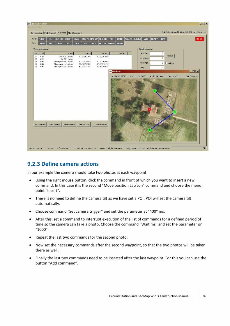
9.2.3 Define camera actions
In our example the camera should take two photos at each waypoint:
Using the right mouse button, click the command in front of which you want to insert a new command. In this case it is the second "Move position Lat/Lon" command and choose the menu point "Insert".
There is no need to define the camera tilt as we have set a POI. POI will set the camera tilt automatically.
Choose command "Set camera trigger" and set the parameter at "400" ms.
After this, set a command to interrupt execution of the list of commands for a defined period of time so the camera can take a photo. Choose the command "Wait ms" and set the parameter on "1000".
Repeat the last two commands for the second photo.
Now set the necessary commands after the second waypoint, so that the two photos will be taken there as well.
Finally the last two commands need to be inserted after the last waypoint. For this you can use the button “Add command”.

Ground Station and GeoMap Win 3.4 Instruction Manual 37
9.2.4 Flight there and back
Now we will set the automatic flight there and back.
Set the commands:
Auto take-off.
Set height 6000 (for 60 m), to fly there at a safe height.
Set this command after the first waypoint:
Set Height 2500 (for 25 m), to take the photos from this height.
At the end set commands:
Set height 6000 (for 60 m), to fly back at a safe height.
coming home.
Auto landing.

Ground Station and GeoMap Win 3.4 Instruction Manual 38
Note: The position numbers of the waypoints now have a different figure from the beginning. The number of green waypoints equals the position number of the associated “Move ... “ commands in the list.
Note: Keep in mind that the flight there and back is not yet shown on the map, as the program doesn't know yet where the starting point will be.

Ground Station and GeoMap Win 3.4 Instruction Manual 39
9.3 Tutorial - Transfer and Start a Mission
Connect the ZX5 with the "Groundstation" software. Transfer the completed list by using option "Send mission" on the tab "WayPoint".
lf you want to update the mission during the flight, stop the waypoint-flight-mode by activating the PH-flight-mode. Transfer the updated mission by using the button "Send Mission" and then start the WP-flight-mode again.
Note: When changing the batteries the stored mission in the ZX5 will be deleted for security reasons. After changing the batteries you need to transfer the mission again.
The length of the mission CAN be longer than the maximum available flight time. Pay attention to the battery charge status at all times during the flight and cancel the mission if necessary. lf so, divide the mission into several shorter missions. It is better to calculate the approximate flight time during the planning stage. Try to start your mission on the farthest point. That way the ZX5 will work its way back towards the starting point (you) and you can react faster in case of a low battery charge status.
9.4 Tutorial – Wizard "Panorama"
The wizard "Panorama" helps you to define a list of commands to take all the photos for a 360-degree-panorama-photo.
There are three values needed for this.
Camera tilt (deg): The tilt of the camera (0° = horiz., 90° = vertical)
Angular distance (deg): The angular distance between the photo positions. For example: at 120° three photos will be taken.
Trigger hold (ms): The trigger time.

Ground Station and GeoMap Win 3.4 Instruction Manual 40
The generated list of commands doesn't contain any position data. It can be started in any desired position and height. The ZX5 remains in the current position.
The generated list of commands can be changed according to your requirements. For example, you could fly to several waypoints and at each activating the panorama function:
9.5 Tutorial - Wizard “Matrix”
The wizard "Matrix" helps you to define a list of commands to fly in parallel lines to take photos with overlap. For this it is necessary to provide the details of the lens and the desired overlap. This is critical to calculate the necessary height and distance needed between the photos. In addition the wizard calculates the achieved pixel resolution which you can influence indirectly by modifying height.

Ground Station and GeoMap Win 3.4 Instruction Manual 41
The fields have the following significance:
Matrix Data (calculated value depending on Camera Data and Overlap):
Height (m): Calculates necessary flight level (from starting level).
Raster XY (m): Calculates land area that will be shown in one picture.
Trigger hold (ms): Interval time between the photos Can be defined manually, if “OnTheWay = no”. Calculates, if “OnTheWay = yes”.
OnTheWay: Taking a photo at intermediate waypoints (OnTheWay = no) or taking a photo after “Background Trigger” (OnTheWay = yes).
Overlap (%):
X: Desired overlap in X-direction
Y: Desired overlap in Y-direction
Flight Data:
Matrix origin: Coordinates of the first photo position
Area width XY (m): Length/width of the flying field
Direction (deg): Alignment of the ZX5 (camera)
Camera tilt (deg): Tilt of the camera (90° = vertically down)
Speed (cm/s): Flight speed of the ZX5

Ground Station and GeoMap Win 3.4 Instruction Manual 42
Camera Data:
CCD XY (mm): Dimensions of the image sensors
CCD XY (Pixel): Resolution of the image sensors
Lens F (mm): Focal length of the lens
Distance (m): Distance between lens and ground (has to be entered manual)
Calc XY (m): Calculated ground area, that is shown on the image sensor
mm/Pixel XY: Calculated pixel resolution
Actions:
Calculates the matrix data on the basis of the camera data (can also be activated with "Enter").
Selection box for lens and camera.
Saves adjusted values in the entry "Custom".
9.5.1 Example 1 – “OnTheWay = Yes”
Open GeoMap. Upload or define a map combination (Map) of the area that you want to fly over.
Now place three waypoints around the area that should be flown, to define it. The lines should be approximately at right angles to each other.
For the alignment of the camera, the angle of the line between WP1 and WP2 is crucial, in this example ca. 40°.
Now open the "Matrix wizard":

Ground Station and GeoMap Win 3.4 Instruction Manual 43
From the three waypoints the values "Matrix origin", "Area width" and "Direction" are generated.
Now the camera data has to be specified. The camera can be either found in the drop down list or you have to insert the values manually.
Next, the desired image overlap for X and Y has to be inserted.
With the next entry you can decide if you want the photos to be taken on intermediate waypoints (OnTheWay = no) or if the photos should be taken in a fixed time interval per “Background Trigger” (OnTheWay = yes).
For this example we will take the Canon 1 D Mark ll with a 5Omm lens, an overlap of 60%, and the method “Trigger per time interval” (OnTheWay = yes). With this method the program calculates the needed time interval for the trigger activation.
Ground Station and GeoMap Win 3.4 Instruction Manual 44
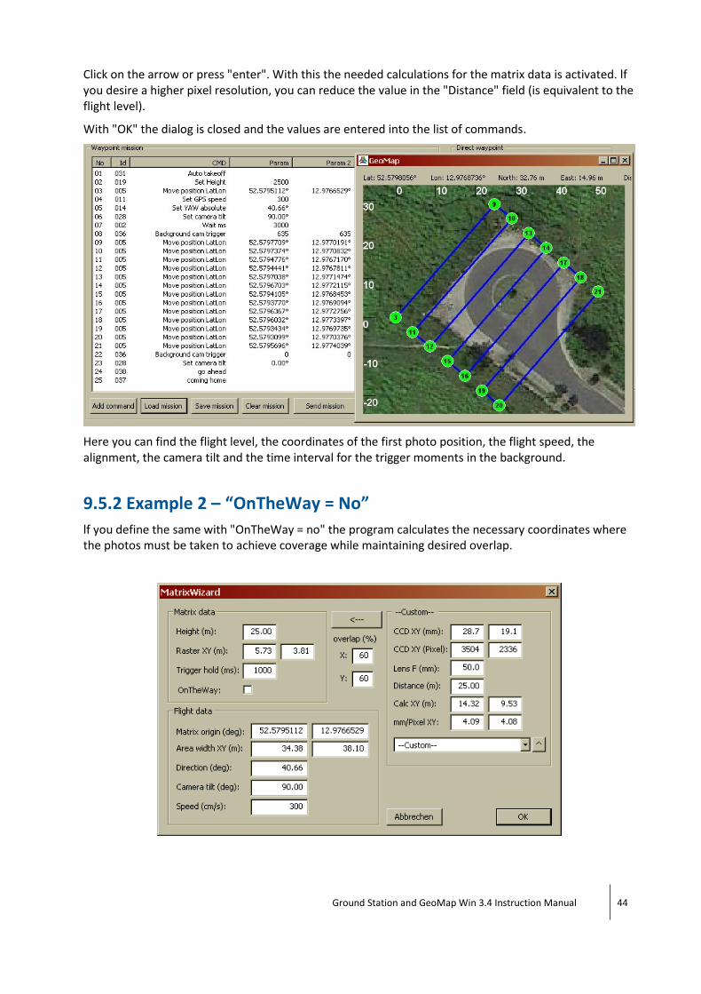
Click on the arrow or press "enter". With this the needed calculations for the matrix data is activated. lf you desire a higher pixel resolution, you can reduce the value in the "Distance" field (is equivalent to the flight level).
With "OK" the dialog is closed and the values are entered into the list of commands.
Here you can find the flight level, the coordinates of the first photo position, the flight speed, the alignment, the camera tilt and the time interval for the trigger moments in the background.
9.5.2 Example 2 – “OnTheWay = No”
lf you define the same with "OnTheWay = no" the program calculates the necessary coordinates where the photos must be taken to achieve coverage while maintaining desired overlap.

Ground Station and GeoMap Win 3.4 Instruction Manual 45
This can be seen in the list of commands, as there is no “Background Trigger” and there are more necessary waypoints between changes in direction at which the photos are triggered.
As you can see, this method generates considerably more commands.
9.5.3 Comparison "OnTheWay" Methods
Method Differences Advantages
OnTheWay = yes Take photos in a fixed time interval Requires lesser flight time
OnTheWay = no Takes photos at additional intermediate waypoints
The line is flown more precisely in strong winds
9.6 Tutorial - "Custom"- Camera (Matrixwizard)
The matrix wizard helps you find the correct values for flight level and photo position by showing the flight level, the overlap and the used camera.
In the dialog "Matrix Wizard" you can find a drop down list in which you can choose the camera and lens to calculate the necessary values for the matrix-flight. lf your camera and lens are not included in this list you can enter your own values and save them permanently with the "Custom" option.

Ground Station and GeoMap Win 3.4 Instruction Manual 46
How to define your own values:
Choose a camera which has roughly the same values as your own camera
Change the fields that differ: “CCD XY (mm)”, “CCD XY (Pixel)”, “Lens F (mm)”.
The pixel resolution will be calculated instantly. Adjust the field “Distance (m)” to set the desired pixel density.
Click on the button to save the values.
You can retrieve these values by choosing the camera model “Custom”.
9.7 Tutorial - Wizard “Line”
With the line-wizard a line between two coordinates can be drawn. In between the two waypoints, more waypoints at even intervals will be placed. At each waypoint one photo will be taken.
The following values are needed:
Coordinate 1: Start position of the line.
Coordinate 2: End position of the line.
Interval (m): Distance between the additional WP's
Camera tilt (deg): Tilt of the camera (0° = horiz.)
Trigger hold (ms): The trigger time
In this example a photo will be taken every 10m vertically down. The ZX5 will hover at the waypoints.

Ground Station and GeoMap Win 3.4 Instruction Manual 47
To take the photos at the waypoints in flyby without the ZX5 remaining stationary, the following commands must be added:
Set smooth start = 0
Set smooth stop = 0
9.8 Tutorial – “Background Trigger”
“Background Trigger” is a command that can be used in an existing mission. This command defines the continuous taking of photos in the background. That means that the list of commands will be processed normally, while the photos are being taken in defined time intervals.
In this example, we will define the waypoints as transit points, meaning that the ZX5 will not stand still at the intermediate waypoints. Then the ZX5 is aligned on 32,53°. Afterwards the camera tilt is set on 90° - vertically straight down. Then the ZX5 flies to the first waypoint and starts the continuous trigger function that is active in the background. Next the following three waypoints are approached. Finally the ZX5 will remain stationary on the last waypoint and stop the background trigger function.

Ground Station and GeoMap Win 3.4 Instruction Manual 48
9.9 Tutorial - "Go to No"
"Go to No" (Meaning: Go to command with position number ... ) is a command which can be used in a mission. With this, certain parts of the list of commands can be suspended.
9.9.1 Example 1
You have planned a mission with many waypoints. During the mission, you notice that the battery capacity will not be sufficient for the whole mission. You have to cancel the process and carry on with a new pair of batteries.
Before you interfere, take a look at the command counter (named waypoint x/y and is located on the tab "waypoint" below the list of commands). The first number is the current command and the second number the total number of commands (e.g. 34/90 = at the moment command 34 is being processed with a total of 90 commands). Now you can interrupt the mission and change the batteries. By adding the command "Go to No" the ZX5 continues the mission at command 34.
Note:
Insert the "Go to No command" at a sensible place, for example after the basic settings commands like "Set smooth stop" or "Set YAW absolute".
By inserting the command "Go to No" all following commands get a new position number, the old number plus 1. The command that was on position 34 before now has the position 35. You have to consider this when setting this command.

Ground Station and GeoMap Win 3.4 Instruction Manual 49
9.9.2 Example 2
You want to record a video sequence. The ZX5 shall fly a previously defined flight path several times until you interrupt manually.
Define the basic setting commands and the flight path. To repeat the flight path endlessly, add the command "Go to No" with the position number of the command to start the flight path, at the end.
Note: The path from the last waypoint back to the first waypoint is not shown in GeoMap. Keep in mind that there might be obstacles in the way. In this case you have to either set more waypoints to avoid the obstacles or set the return flight level higher.
9.10 Tutorial - "Go to Until Reached Position"
"Go to until reached position" (Meaning: jump to the command with the position number ... in the list of commands as long as the defined coordinates have not been reached yet) is a command to be used in a mission. For example:
You want the ZX5 to slowly fly a defined line while taking photos in all four cardinal directions. For this you have to set two waypoints, start the "Background Trigger" when the first waypoint is reached and define a loop of commands that makes the ZX5 change its direction of view continuously until it reaches the second waypoint.
Note: lf you have set the command "Go to until reached position" and insert or delete other commands afterwards, the position number in the list of commands changes. Keep in mind, you will need to adjust these numbers.

Ground Station and GeoMap Win 3.4 Instruction Manual 50
9.11 Tutorial - Flying Diagonal Autonomously
In this tutorial you will learn how to reach a waypoint in a defined height diagonal, instead of climbing vertically to the height level first and then flying to the position. This method saves flight time.
As a standard, the command "Set Height" and "Move position" interrupt the processing of the list of commands until the height or coordinates are reached.
This is ensured by the flags "Set wait to reach position flag" and "Set wait to reach height flag" that have the predefined value 1. In the following example we want to fly to a waypoint at 100m altitude:
To reach this position diagonal we have to complete the list of commands as follows: