Embed Size (px)
Citation preview
Ice Cream/ Gelato Cases Models: EGIF
EGIF
Instruction Manual
Tel : 416-663-3051 Fax : 416-663-5793Toll Free : 1-888-408-8819
124 Norfinch Dr. Toronto, ON. M3N 1X1
REFRIGERATION LTD.
REFRIGERATION LTD
Ice Cream/ Gelato Dispenser | www.igloorefrigeration.com 2
Contents
1 UNLOADING ..................................................................................................................................................... 3
2 PROPERTIES OF THE UNIT.................................................................................................................................. 3
2.1. Purpose .................................................................................................................................................... 3 2.2. Description of the unit............................................................................................................................... 3 2.3. Technical data ........................................................................................................................................... 5
3. PREPARING THE DEVICE FOR START UP ............................................................................................................ 6
3.1. Installation requirements .......................................................................................................................... 6 3.2. Unit Location ............................................................................................................................................ 6 3.3. Connection and start-up ............................................................................................................................ 7
4. UNIT START UP ............................................................................................................................................... 9
4.1. Temperature regulation ............................................................................................................................ 8 5. MAINTENANCE .............................................................................................................................................. 11
5.1 Cleaning and maintenance ....................................................................................................................... 11 6. SERVICE ......................................................................................................................................................... 12
6.1 Faults identification and repair ................................................................................................................. 12 6.2 Service ..................................................................................................................................................... 13
List of Figures & Tables
Figure 1 EGIF - Overview ..................................................................................................................................... 4 Figure 2 Layout of containers .............................................................................................................................. 4 Figure 3 Levelling legs .......................................................................................................................................... 6 Figure 4 Control panel ......................................................................................................................................... 7 Figure 5 “Carel” themostat control panel ............................................................................................................ 8 Figure 6 Cleaning the condenser ........................................................................................................................ 12 Table 1 Containers ............................................................................................................................................... 4 Table 2 Technical data ......................................................................................................................................... 5
REFRIGERATION LTD
Ice Cream/ Gelato Dispenser | www.igloorefrigeration.com 3
1 UNLOADING
The unit should be transported in vertical position and properly secured and packed.
2 PROPERTIES OF THE UNIT
2.1. Purpose
“EGIF” cases are universal freezing devices that are aimed for displaying and short-lasting storage of scooped ice cream/ Gelato in temperature ranging between -20ºC and -10ºC with ambient temperature of +24ºC and relative air humidity up to 55%, depending on the environment of the unit location.
2.2. Description of the unit
“EGIF” display units have dynamic cooling. These display cases are equipped with automatic defrosting and automatic condensate evaporation. The electronic thermostat co-operate module to monitor and send signals when the temperature inside the equipment gets too low or too high. Our equipment is manufactured in accordance to modern technologies and has all certificates required by law.
The description in this box signifies important information for user security and for proper operation of the device.
REFRIGERATION LTD
Ice Cream/ Gelato Dispenser | www.igloorefrigeration.com 4
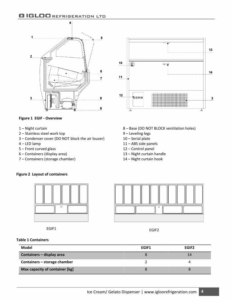
Figure 1 EGIF - Overview 1 – Night curtain 2 – Stainless steel work top 3 – Condenser cover (DO NOT block the air louver) 4 – LED lamp 5 – Front curved glass 6 – Containers (display area) 7 – Containers (storage chamber)
8 – Base (DO NOT BLOCK ventilation holes) 9 – Leveling legs 10 – Serial plate 11 – ABS side panels 12 – Control panel 13 – Night curtain handle 14 – Night curtain hook
Table 1 Containers
Model EGIF1 EGIF2
Containers – display area 8 14
Containers – storage chamber 2 4
Max capacity of container [kg] 8 8
EGIF1
EGIF2
Figure 2 Layout of containers
REFRIGERATION LTD
Ice Cream/ Gelato Dispenser | www.igloorefrigeration.com 5
2.3. Technical data
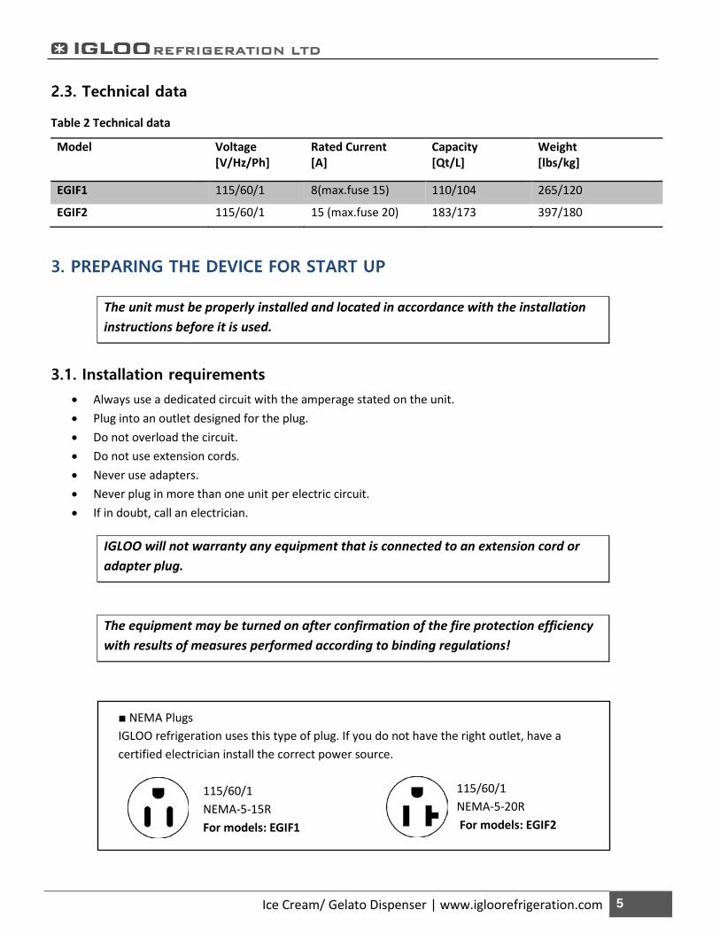
Table 2 Technical data
Model Voltage [V/Hz/Ph]
Rated Current [A]
Capacity [Qt/L]
Weight [lbs/kg]
EGIF1 115/60/1 8(max.fuse 15) 110/104 265/120
EGIF2 115/60/1 15 (max.fuse 20) 183/173 397/180
3. PREPARING THE DEVICE FOR START UP
The unit must be properly installed and located in accordance with the installation instructions before it is used.
3.1. Installation requirements
• Always use a dedicated circuit with the amperage stated on the unit. • Plug into an outlet designed for the plug. • Do not overload the circuit. • Do not use extension cords. • Never use adapters. • Never plug in more than one unit per electric circuit. • If in doubt, call an electrician.
IGLOO will not warranty any equipment that is connected to an extension cord or adapter plug.
The equipment may be turned on after confirmation of the fire protection efficiency with results of measures performed according to binding regulations!
■ NEMA Plugs IGLOO refrigeration uses this type of plug. If you do not have the right outlet, have a certified electrician install the correct power source.
115/60/1 NEMA-5-15R For models: EGIF1
115/60/1 NEMA-5-20R For models: EGIF2
REFRIGERATION LTD
Ice Cream/ Gelato Dispenser | www.igloorefrigeration.com 6
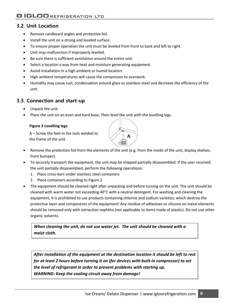
Figure 3 Levelling legs
A – Screw the feet in the nuts welded to the frame of the unit
3.2. Unit Location
• Remove cardboard angles and protective foil. • Install the unit on a strong and leveled surface. • To ensure proper operation the unit must be leveled from front to back and left to right. • Unit may malfunction if improperly leveled. • Be sure there is sufficient ventilation around the entire unit. • Select a location a way from heat and moisture generating equipment. • Avoid installation in a high ambient or humid location. • High ambient temperatures will cause the compressor to overwork. • Humidity may cause rust, condensation around glass or stainless steel and decrease the efficiency of the
unit.
3.3. Connection and start-up
• Unpack the unit. • Place the unit on an even and hard base. Then level the unit with the levelling legs.
• Remove the protection foil from the elements of the unit (e.g. from the inside of the unit, display shelves,
front bumper). • To securely transport the equipment, the unit may be shipped partially disassembled. If the user received
the unit partially disassembled, perform the following operations: 1. Place cross-bars under stainless steel containers 2. Place containers according to Figure 2
• The equipment should be cleaned right after unpacking and before turning on the unit. The unit should be cleaned with warm water not exceeding 40°C with a neutral detergent. For washing and cleaning the equipment, it is prohibited to use products containing chlorine and sodium varieties, which destroy the protective layer and components of the equipment! Any residue of adhesives or silicone on metal elements should be removed only with extraction naphtha (not applicable to items made of plastic). Do not use other organic solvents.
When cleaning the unit, do not use water jet. The unit should be cleaned with a moist cloth.
After installation of the equipment at the destination location it should be left to rest for at least 2 hours before turning it on (for devices with built-in compressor) to set the level of refrigerant in order to prevent problems with starting up. WARNING: Keep the cooling circuit away from damage!
REFRIGERATION LTD
Ice Cream/ Gelato Dispenser | www.igloorefrigeration.com 7
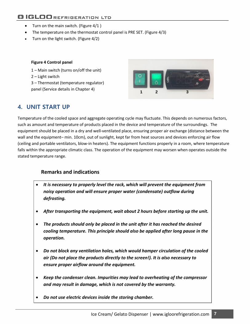
• Turn on the main switch. (Figure 4/1 ) • The temperature on the thermostat control panel is PRE SET. (Figure 4/3) • Turn on the light switch. (Figure 4/2)
4. UNIT START UP
Temperature of the cooled space and aggregate operating cycle may fluctuate. This depends on numerous factors, such as amount and temperature of products placed in the device and temperature of the surroundings. The equipment should be placed in a dry and well-ventilated place, ensuring proper air exchange (distance between the wall and the equipment– min. 10cm), out of sunlight, kept far from heat sources and devices enforcing air flow (ceiling and portable ventilators, blow-in heaters). The equipment functions properly in a room, where temperature falls within the appropriate climatic class. The operation of the equipment may worsen when operates outside the stated temperature range.
Remarks and indications
• It is necessary to properly level the rack, which will prevent the equipment from noisy operation and will ensure proper water (condensate) outflow during defrosting.
• After transporting the equipment, wait about 2 hours before starting up the unit.
• The products should only be placed in the unit after it has reached the desired cooling temperature. This principle should also be applied after long pause in the operation.
• Do not block any ventilation holes, which would hamper circulation of the cooled air (Do not place the products directly to the screen!). It is also necessary to ensure proper airflow around the equipment.
• Keep the condenser clean. Impurities may lead to overheating of the compressor and may result in damage, which is not covered by the warranty.
• Do not use electric devices inside the storing chamber.
Figure 4 Control panel
1 – Main switch (turns on/off the unit) 2 – Light switch 3 – Thermostat (temperature regulator) panel (Service details in Chapter 4)
1 2 3
REFRIGERATION LTD
Ice Cream/ Gelato Dispenser | www.igloorefrigeration.com 8
• When the unit is used without the need to display goods (night work; off hours), it is recommended to use the night curtain to reduce electricity consumption.
4.1. Temperature regulation The thermostat is to obtain the set temperature within the equipment and maintain it within the determined temperature ranges. The manufacturer enters all settings of temperature regulators required for normal functioning of the equipment. Before primary actuation the user should control and possibly set the required temperature inside the equipment on the control panel.
Digital display – displays the current temperature inside the equipment
It is forbidden to interfere with systemic parameters of the thermostat, as this can lead to serious consequences, including the damage of the cooling unit!
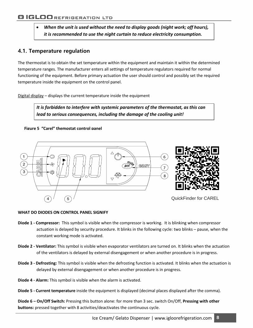
WHAT DO DIODES ON CONTROL PANEL SIGNIFY
Diode 1 - Compressor: This symbol is visible when the compressor is working. It is blinking when compressor actuation is delayed by security procedure. It blinks in the following cycle: two blinks – pause, when the constant working mode is activated.
Diode 2 - Ventilator: This symbol is visible when evaporator ventilators are turned on. It blinks when the actuation of the ventilators is delayed by external disengagement or when another procedure is in progress.
Diode 3 - Defrosting: This symbol is visible when the defrosting function is activated. It blinks when the actuation is delayed by external disengagement or when another procedure is in progress.
Diode 4 - Alarm: This symbol is visible when the alarm is activated.
Diode 5 - Current temperature inside the equipment is displayed (decimal places displayed after the comma).
Diode 6 – On/Off Switch: Pressing this button alone: for more than 3 sec. switch On/Off, Pressing with other buttons: pressed together with 8 activities/deactivates the continuous cycle.
Figure 5 “Carel” themostat control panel
QuickFinder for CAREL
REFRIGERATION LTD
Ice Cream/ Gelato Dispenser | www.igloorefrigeration.com 9
Diode 7 – Set/ Mute: Pressing this button alone: 1 sec. displays /sets the set point, more than 3 sec. accesses the parameter setting menu (enter password 22), mutes the audible alarm (buzzer), Start Up: hold the set/mute button for 1 sec. RESET current EY set / Pressed together (7 and 8) activate parameter reset procedure. Diode 8 – Defrost: Pressing this button alone: more than 3 sec. activates/deactivates the defrost. Pressing with other buttons: pressed together with 6 activates/deactivates the continuous cycle, Start Up: hold for 1 sec. displays firmware version.
SETTING THE DESIRED TEMPERATURE
- Press the set button for 1 second leading value shall be displayed on the screen
- Increase or decrease the leading value by means of and , until the desired value shall be obtained;
- Press the set button once again in order to confirm the new value of the setting point.
MANUAL INPUT OF THE DEFROSTING CYCLE
Defrosting shall be released in an automatic mode. It is possible to force defrosting at any moment by pressing and holding the defrost switch for minimum 5 seconds.
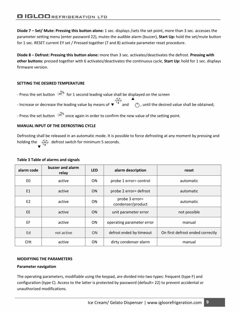
Table 3 Table of alarms and signals
alarm code buzzer and alarm relay LED alarm description reset
E0 active ON probe 1 error= control automatic
E1 active ON probe 2 error= defrost automatic
E2 active ON probe 3 error= condenser/product automatic
EE active ON unit parameter error not possible
EF active ON operating parameter error manual
Ed not active ON defrost ended by timeout On first defrost ended correctly
CHt active ON dirty condenser alarm manual
MODIFYING THE PARAMETERS
Parameter navigation
The operating parameters, modifiable using the keypad, are divided into two types: frequent (type F) and configuration (type C). Access to the latter is protected by password (default= 22) to prevent accidental or unauthorized modifications.
REFRIGERATION LTD
Ice Cream/ Gelato Dispenser | www.igloorefrigeration.com 10
Accessing the type F parameters:
-Press the SET button for more than 3 s (if there are active alarms, mute the buzzers). The display shows the parameter code ‘PS’ (password);
- Use the UP and DOWN buttons to scroll the parameters. The LED corresponding to the category of parameters will be on;
- Press SET to display the value associated with the parameter
- Increase or decrease the value using the UP or DOWN button respectively;
- Press SET to temporarily save the new value and display the parameter again;
- Repeat the procedure for any other parameters that need to be modified;
- Press the SET button for more than 3 s to permanently save the parameters and exit the parameter setting procedure.
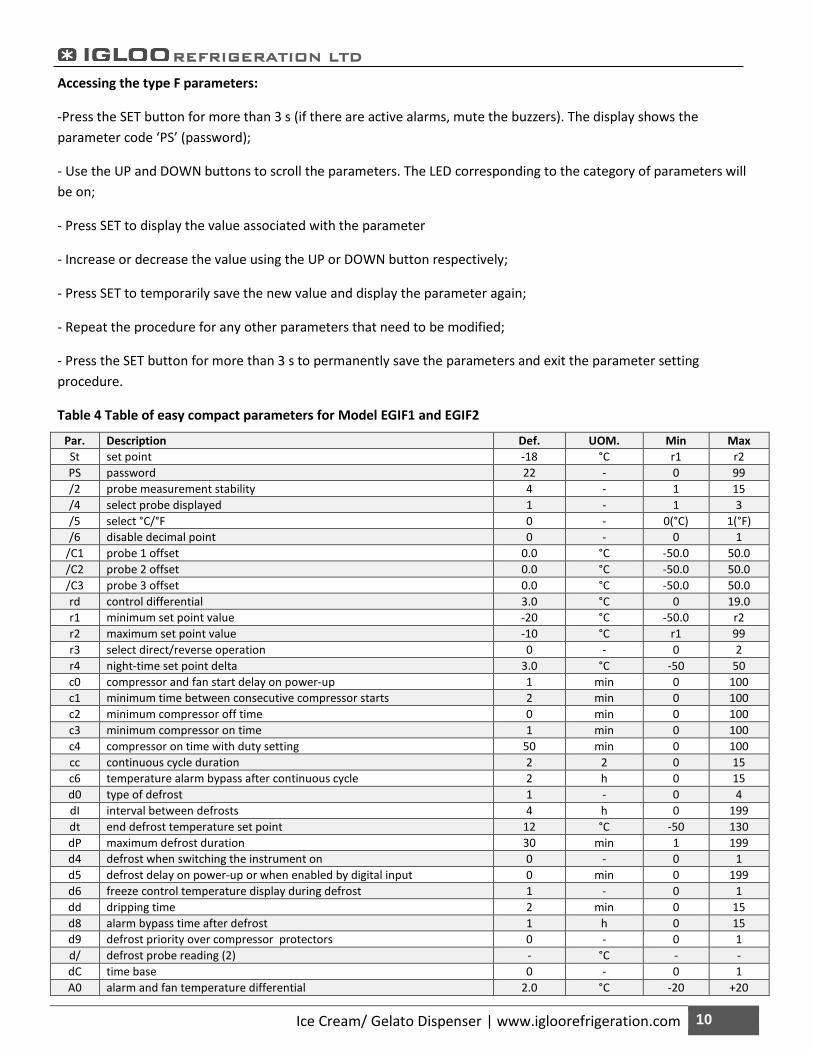
Table 4 Table of easy compact parameters for Model EGIF1 and EGIF2
Par. Description Def. UOM. Min Max St set point -18 °C r1 r2 PS password 22 - 0 99 /2 probe measurement stability 4 - 1 15 /4 select probe displayed 1 - 1 3 /5 select °C/°F 0 - 0(°C) 1(°F) /6 disable decimal point 0 - 0 1
/C1 probe 1 offset 0.0 °C -50.0 50.0 /C2 probe 2 offset 0.0 °C -50.0 50.0 /C3 probe 3 offset 0.0 °C -50.0 50.0 rd control differential 3.0 °C 0 19.0 r1 minimum set point value -20 °C -50.0 r2 r2 maximum set point value -10 °C r1 99 r3 select direct/reverse operation 0 - 0 2 r4 night-time set point delta 3.0 °C -50 50 c0 compressor and fan start delay on power-up 1 min 0 100 c1 minimum time between consecutive compressor starts 2 min 0 100 c2 minimum compressor off time 0 min 0 100 c3 minimum compressor on time 1 min 0 100 c4 compressor on time with duty setting 50 min 0 100 cc continuous cycle duration 2 2 0 15 c6 temperature alarm bypass after continuous cycle 2 h 0 15 d0 type of defrost 1 - 0 4 dI interval between defrosts 4 h 0 199 dt end defrost temperature set point 12 °C -50 130 dP maximum defrost duration 30 min 1 199 d4 defrost when switching the instrument on 0 - 0 1 d5 defrost delay on power-up or when enabled by digital input 0 min 0 199 d6 freeze control temperature display during defrost 1 - 0 1 dd dripping time 2 min 0 15 d8 alarm bypass time after defrost 1 h 0 15 d9 defrost priority over compressor protectors 0 - 0 1 d/ defrost probe reading (2) - °C - - dC time base 0 - 0 1 A0 alarm and fan temperature differential 2.0 °C -20 +20
REFRIGERATION LTD
Ice Cream/ Gelato Dispenser | www.igloorefrigeration.com 11
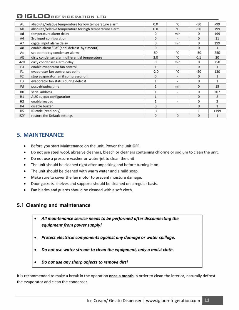
5. MAINTENANCE
• Before you start Maintenance on the unit, Power the unit OFF. • Do not use steel wool, abrasive cleaners, bleach or cleaners containing chlorine or sodium to clean the unit. • Do not use a pressure washer or water-jet to clean the unit. • The unit should be cleaned right after unpacking and before turning it on. • The unit should be cleaned with warm water and a mild soap. • Make sure to cover the fan motor to prevent moisture damage. • Door gaskets, shelves and supports should be cleaned on a regular basis. • Fan blades and guards should be cleaned with a soft cloth.
5.1 Cleaning and maintenance
• All maintenance service needs to be performed after disconnecting the equipment from power supply!
• Protect electrical components against any damage or water spillage.
• Do not use water stream to clean the equipment, only a moist cloth.
• Do not use any sharp objects to remove dirt!
It is recommended to make a break in the operation once a month in order to clean the interior, naturally defrost the evaporator and clean the condenser.
AL absolute/relative temperature for low temperature alarm 0.0 °C -50 +99 AH absolute/relative temperature for high temperature alarm 0.0 °C -50 +99 Ad temperature alarm delay 0 min 0 199 A4 3rd input configuration 0 - 0 11 A7 digital input alarm delay 0 min 0 199 A8 enable alarm “Ed” (end defrost by timeout) 0 - 0 1 Ac set point dirty condenser alarm 60 °C -50 250 AE dirty condenser alarm differential temperature 3.0 °C 0.1 20
Acd dirty condenser alarm delay 0 min 0 250 F0 enable evaporator fan control 1 - 0 1 F1 evaporator fan control set point -2.0 °C -50 130 F2 stop evaporator fan if compressor off 0 - 0 1 F3 evaporator fan status during defrost 1 - 0 1 Fd post-dripping time 1 min 0 15 H0 serial address 1 - 0 207 H1 AUX output configuration 1 - 0 2 H2 enable keypad 1 - 0 2 H4 disable buzzer 0 0 1 H5 ID code (read-only) -1 - 1 +199 EZY restore the Default settings 0 0 0 1
REFRIGERATION LTD
Ice Cream/ Gelato Dispenser | www.igloorefrigeration.com 12
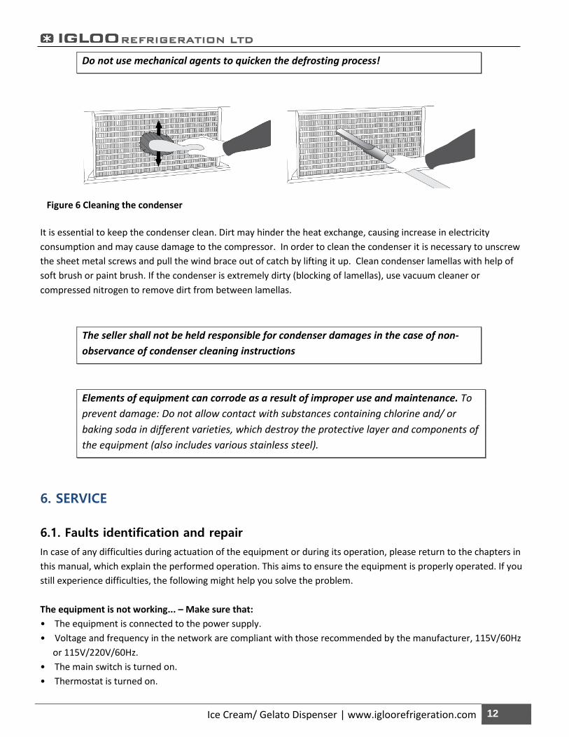
Do not use mechanical agents to quicken the defrosting process!
It is essential to keep the condenser clean. Dirt may hinder the heat exchange, causing increase in electricity consumption and may cause damage to the compressor. In order to clean the condenser it is necessary to unscrew the sheet metal screws and pull the wind brace out of catch by lifting it up. Clean condenser lamellas with help of soft brush or paint brush. If the condenser is extremely dirty (blocking of lamellas), use vacuum cleaner or compressed nitrogen to remove dirt from between lamellas.
The seller shall not be held responsible for condenser damages in the case of non-observance of condenser cleaning instructions
Elements of equipment can corrode as a result of improper use and maintenance. To prevent damage: Do not allow contact with substances containing chlorine and/ or baking soda in different varieties, which destroy the protective layer and components of the equipment (also includes various stainless steel).
6. SERVICE
6.1. Faults identification and repair
In case of any difficulties during actuation of the equipment or during its operation, please return to the chapters in this manual, which explain the performed operation. This aims to ensure the equipment is properly operated. If you still experience difficulties, the following might help you solve the problem. The equipment is not working... – Make sure that: • The equipment is connected to the power supply. • Voltage and frequency in the network are compliant with those recommended by the manufacturer, 115V/60Hz
or 115V/220V/60Hz. • The main switch is turned on. • Thermostat is turned on.
Figure 6 Cleaning the condenser
REFRIGERATION LTD
Ice Cream/ Gelato Dispenser | www.igloorefrigeration.com 13
The equipment is operating, but the light is off... – Make sure that: • Light switch is turned on. • Lamp or starting switch of the equipment is not burnt. Water leakage from under the device: • Check whether the equipment is properly levelled. • Empty the condensate container. The equipment does not reach the proper temperature, the light is on... – Make sure that: • The main switch is on. • Temperature setting on the thermostat is properly set. • Thermostat works properly. • The condenser is clean, if necessary – clean the condenser. • Ambient temperature does not exceed 25ºC. • Enough time has passed for products to be cooled. • Ventilation holes are not blocked. The equipment is working too loud... – Make sure that: • The equipment is standing stably and properly levelled. • Furniture adjoining the equipment does not vibrate when self-contained compressor is working.
A noise made by the operating device is normal. These units are equipped with ventilators, engines and compressors, which turn on and off automatically. Each compressor makes certain noises when operating. These sounds are made by the aggregate engine and by cooling agent flowing through the circuit. This phenomenon constitutes a technical feature of cooling devices and does not signify equipment failure.
Steam precipitation on glasses is normal in the event of high relative air humidity exceeding 55% and does not require calling for service.
6.2 Service
IGLOO Refrigeration service
Telephone number: 416-663-3051 or (toll free) 1-888-408-8819
E-mail: [email protected]
If after checking points described in chapter 6.1 “Faults identification and repair” and the unit still does not work properly,
Please contact Technical Service @IGLOO Refrigeration.