Embed Size (px)
Citation preview
Instruction Manual
IM70827-GB5 2002-12
ThinkTop® AS-Interface 29.5 - 31.6 VDC
Patented Sensor SystemRegistered Design
Registered Trademark

Alfa LavalCompany Name
Bjarne Søndergaard
Declaration of Conformity
The designating company
Designation
is in conformity with the following directives with amendments:
- Low Voltage Directive 73/23/EEC- EMC Directive 89/336/EEC
hereby declare that
Denomination Type Year
Address
Phone No.
NameTitle
Company Signature
Vice President, R & D
Alfa Laval
Albuen 31, DK-6000 Kolding, Denmark
+45 79 32 22 00
Top Unit for Valve Control & Indication ThinkTop® AS-Interface
3

4

The information contained herein is correct at the time of issue but may be subject to change without prior notice.
5
Table of contents
1. Safety .................................................................................................... 61.1 Important information ....................................................................... 61.2 Warning signs .................................................................................. 61.3 Safety precautions ........................................................................... 6
2. General information ............................................................................. 72.1 AS-Interface in general .................................................................... 7
3. Technical specifications ...................................................................... 83.1 ThinkTop®, AS-Interface 29.5 - 31.6 VDC ........................................ 8
4. Installation .......................................................................................... 134.1 Installation on air actuators ............................................................. 134.2 Installation on Series 700 valves ..................................................... 164.3 Air connections .............................................................................. 174.4 Electrical connection, internal ........................................................ 18
5. Setup diagram .................................................................................... 205.1 ThinkTop® setup utilising IR keypad .............................................. 205.2 ThinkTop® setup utilising local 'I' and 'II' keys................................ 22
6. Fault finding ....................................................................................... 246.1 Fault finding and LEDs ................................................................... 24
7. Maintenance ....................................................................................... 267.1 Dismantling of ThinkTop® ............................................................... 267.2 Assembly of ThinkTop® .................................................................. 287.3 Dismantling and assembly of Series 700 valves ............................. 30
8. Parts list .............................................................................................. 328.1 ThinkTop® AS-Interface 29.5-31.6 VDC ........................................ 328.2 ThinkTop® Series 700 valves ......................................................... 34

6
1.1 Important information1.2 Warning signs1.3 Safety precautions
1. Safety
Unsafe practices and other important information are emphasized in this manual.Warnings are emphasized by means of special signs.All warnings in the manual are summarized on this page.Pay special attention to the instructions below so that severe personal injury or damage to the top unit are avoided.
Always read the manual before using the top unit!
WARNING!Indicates that special procedures must be followed to avoid severe personal injury.
CAUTION!Indicates that special procedures must be followed to avoid damage to the ThinkTop®.
NOTE!Indicates important information to simplify or clarify practices.
Installation- Always observe the technical specifications (see chapter 3).- Never install the ThinkTop® before valve or relay is in a safe position.- If welding close to the ThinkTop®: Always earth close to the welding area.- Disconnect the ThinkTop®.
- Always have the ThinkTop® electrically connected by authorized personnel.
Maintenance- Always read the technical specifications thoroughly (see chapter 3).----- Always fit the seals between valve and ThinkTop® correctly.- Never service the ThinkTop® before valve or relay is in a safe position.- Never service the ThinkTop® with valve/actuator under pressure.
- Never clean the ThinkTop® with high pressure cleaning equipment.- Never use cleaning agents when cleaning the ThinkTop®. Check with cleaning agent supplier.
General warning:
Dangerous electrical voltage:
Caustic agents:

7
2. General information 2.1 AS-Interface in general
The ThinkTop® is designed to ensure optimum valve control in conjunction with Alfa Laval valves and it is compatible with mostPLC systems (Programmable Logic Controllers) with AS-Interface.
The ThinkTop® can be equipped with 0-3 solenoid valves. The solenoids are electrically controlled by the AS-Interface and whenactivated the compressed air is activating the air actuator. All solenoids have build-in throttle function on both air inlet and outletwhich means that it is possible to control the opening and closing time of the air actuator. The solenoids are also equipped witha manual hold override.
Visual LED lights are constantly indicating the status of the unit: Valve positions, solenoid activated, setup and local fault indicationetc.
The ThinkTop® is characterized by a simple and modular design. It is exchangeable and is prepared for upgrading.

8
3.1.1 "No Touch" sensor system
Type: Alfa Laval “No Touch” System
For wire connections: See section 4.4 "Electrical connection, internal".
FeaturesTolerance programmes.Self adjustment programme (SRC/ARC valves only).Built-in maintenance monitor.Setup by internal pushbuttons or remote control (IR Keypad).Setup and local fault supervision.Setup saved at power shutdown.Visual LED Indicator lights.
Sensor SystemUnique “No Touch” sensor system without any mechanical sensor adjustments. A magnet is mounted on the valve stem and themagnetic field (axial) is detected by sensor chips inside the sensor unit. The measuring angle from each chip is used to locate thecurrent position of the valve stem with an accuracy of ± 0.1mm. Note that the distance to the magnet can be 5 mm ± 3 mm.
Feedback signalsThe sensor system can be used for 3 feedback signals + 1 status signal = 4 feedback signals. (Two of the feedback signals canbe used for external sensors if necessary).
The status signal is used for detection of the following three conditions:• A set-up is in progress.• Internal error.• Maintenance is required (based on time and/or the self adjustment programme).
Tolerance programme:Individual according to valve types.• Type 1: SRC/ARC and Series 700 valves.• Type 2: LKB (LKLA-T).• Type 3: Unique, SMP-SC Spillage-Free, SRC-PV and AMP.• Type 4: SMP-SC, SMP-TO, SMP-BC, SMP-BCA and SBV.• Type 0: (Preset) All Parameters Set To Default (also valid for MH Koltek valve and SMP-EC
(seat-lift indication not possible for SMP-BC)).Preset and reset values: Tolerance programme No. 0 (± 5mm) and all functions are disabled.NOTE! Important to select the right tolerance programme.
Sensor unit
Sensor board PLC Interface boardIRRx
LED
s
IR Remote control
Terminals Term
inal
s
Internal connections
Solenoid signals (DC)
Solenoid common
External Seat-lift (PNP)
Supply sensors
3. Technical specifications3.1 ThinkTop®, AS-Interface 29.5 - 31.6 VDC
PLC, feedback
Seriallink
ASI P
ASI N
Bus connection
External connections
+5 V

9
Self Adjustment (SRC/ARC valves only)The self adjustment feature is an exceptional aspect of the ThinkTop® design. A programme can be activated to allow anadjustment of the tolerance band if the seals in the valve are being compressed or are worn. When the tolerance band of the unithas been adjusted 0.3 mm, an alert warning will appear in the form of a status signal and a flashing maintenance LED. After 0.5 mmadjustment an alarm warning appears: Loss of feedback signal, status signal and steady maintenance light indicating a minimumof seal left requiring a replacement of the seal.
Built-in Maintenance MonitorThe unit can be preset to indicate when the time for maintenance of the valve has been reached. A status signal and flashingmaintenance LED can be programmed to return after 3, 6, 9 or 12 months or more.
3.1.2 Technical specifications sensor systemSensor accuracy: ± 0,1 mm.Distance to magnet: 5 ± 3 mm.Stroke length: 0.1 - 80 mm.Electrical connection: Direct cable gland entry (hard wired)
PG11 (ø4 - ø10 mm).TerminalsThe terminal row of the sensor unit is equipped with screw terminals for both internal as well as external cables and wires. Theterminals are suitable for wires up to 0.75 mm2 (AWG 19).
Power SupplyThe power supply to the complete unit is taken from the AS-Interface.Supply voltage: 29.5 - 31.6 V DC.Supply current: Max. 45 mA (for sensor unit alone)
(excluding current to the solenoids and the external proximity switches).
The fulfilling of the UL requirements in UL508 requires that the unit is supplied by an isolating source complying with therequirements for class 2 power units (UL1310) or class 2 and 3 transformers (UL1585).
Feedback signalsSignals transmitted over the AS-Interface BUS to the AS-Interface master PLC.
External sensorsThe external sensors are used for seat-lift supervision when seat-lift can not be internally detected. The sensors get their supplyvoltage from the terminal row.The output signals from the sensors are connected to two inputs on the terminal row on the internalsensor unit. If the actual setup is set for internal seat-lift, the corresponding external signal is not used, otherwise the external signallogically controls the corresponding feedback to the PLC.
Supply voltage: As specified for the AS-Interface (typical 24 VDC).Supply current: Max. 15 mA per sensor.Type of sensor: Only 3-wire sensor PNP.Sensor cable length. Max. 3 m.
ASi-bus bit assignmentFor the AS-Interface version, the following bit assignment will be used:
Input bit 0 - feedback # 1 Closed position Output bit 0 – Not connectedInput bit 1 - feedback # 2 Open position Output bit 1 - Solenoid valve 1Input bit 2 - feedback # 3-4 Seat 1 or 2 position Output bit 2 - Solenoid valve 2Input bit 3 - feedback # 5 Status Output bit 3 - Solenoid valve 3
3. Technical specifications 3.1 ThinkTop®, AS-Interface 29.5 - 31.6 VDC

10
ThinkTop® Visual Indications LED Indications
Note: If the programmer wishes to detect a physically closed valve position in an "open valve" sensor position, then there is nolonger any consistence between the sensor valve detection position and the visual indications of the ThinkTop®.
Status signal (feedback # 5) Input bit 3:The status signal is used for five purposes:• To indicate that set-up is going on (LED D).• To indicate an error condition (LED D), (flashing = software error), (steady = hardware error).• To indicate that the time for maintenance has been reached (LED F).• To indicate if there is a conflict in the self adjustment programme (LED F).
Default slave address: 0I/O code: 7 (4 bit bi-directional)I/D code: F (slave without profile)P = F.7.For wire connections: See section 4.4 "Electrical connection, internal".
No. of nodes: Max. 31 ThinkTop® on a single master/gateway.
3.1.3 Technical specifications solenoid valvesSolenoid signalsSolenoid signalsSolenoid signalsSolenoid signalsSolenoid signalsSignals transmitted over the AS-Interface BUS to the AS-Interface master PLC.
Internal connectionsInternal connectionsInternal connectionsInternal connectionsInternal connectionsTerminals for connection of the solenoids mounted internally in the control head.The number of solenoids actually mounted in the control head could be 0 - 3.The signals are taken directly from the terminal row.
3. Technical specifications3.1 ThinkTop®, AS-Interface 29.5 - 31.6 VDC
LED B "Open valve" (Yellow)
IR-Receiver
LED D "Setup/Internal fault" (Red)
LED C "Seat-lift 1/2" (Yellow)
LED E "Solenoid valves" (Green)
LED F "Maintenance" (Orange)
LED A "Closed valve" (Yellow)

11
3. Technical specifications
Technical specifications
Up to 3 solenoid valves in each unit.Type 3/2 or 5/2 valve (only possible with one 5/2 valve).Air supply 300-900 kPa (3-9 bar).Filtered air, max. particles or dirt 0.01 mm.Max. flow 180 l/min.Max. oil content 1.0 ppm.Max. water content 0.0075 kg/kg air.Throughput ø2.5 mm.Air restriction (throttle function) air inlet/outlet.Manual hold override.External air tube connection ø6 mm or 1/4" (specify when ordering).Nominal voltage 24 VDC.Nominal power 1.0 W.Silencer/filter *) Connection possible via ø6 mm or 1/4".
Internal connections (solenoids)
The solenoid drivers can reduce the solenoid power by PWM after the activation time. The PWM function is enabled by ajumper (12, 13). The number of solenoids actually mounted in the Control head could be 0 - 3.
Nominal voltage 24 VDC.Nominal power 1.0 W.Output voltage Must match the selected type of ThinkTop®.Load current Max. 100 mA per solenoid.
Max. current from any number of energized output stagesis 200 mA.
Voltage drop Max. 3 V at 50 mA.Activation time 60 ± 10 ms (time with full power if PWM is enabled).PWM duty cycle 40% (after activation time if PWM is enabled).PWM frequency 2 - 5 kHz.
Materials
Plastic parts Nylon PA12.Steel parts Stainless steel AISI 304 and 316.Seals Nitrile (NBR), EPDM rubber for SMP-EC activator stem.
*) Note! Filter recommended in tropical regions.
3.1 ThinkTop®, AS-Interface 29.5 - 31.6 VDC

12
3. Technical specifications
3.1.4 Micro environment demand specifications
TemperatureWorking: -20°C to +85°C IEC 68-2-1/2Storage: -40°C to +85°C IEC 68-2-1/2Temperature change: -25°C to +70°C IEC 68-2-14
Vibration 10-55 Hz, 0.7 mm IEC 68-2-655-500 Hz, 10g3 x 30 min, 1 octave/min
Drop test IEC 68-2-32
HumidityConstant humidity: +40°C, 21 days, 93% R.H. IEC 68-2-3Cyclic humidity: +25°C/+55°C
12 cycles IEC 68-2-30(working) 93% R.H.
Protection class IP67 IEC 529
Input thresholdInput thresholdInput thresholdInput thresholdInput thresholdVoltage/current: Type 1 input requirements EN 61131-2
EMC Directive 89/336/EEC EN 50081-1, EN 50082-2
AS-Interface Version 2.11 *) EN 50295
UL Approval 8-30 VAC/VDC, Class 2 input,45 mA max. output UL 508-E203255
*) Max. 31 ThinkTop® on a single master/gateway.
3.1 ThinkTop®, AS-Interface 29.5 - 31.6 VDC

13
Step 1
- Always read the technical specifications thoroughly (see chapter 3).- Always have the ThinkTop® electrically connected by authorized personnel.- Never install the ThinkTop® before valve or relay is in a safe position.
Step 21. Fit the air fittings on actuator if not mounted.2. Fit the activator stem (magnet) and tighten carefully with a
spanner.NOTE!The ThinkTop® for the SMP-EC valve has a longer activatorstem going through the shell.Remember O-ring.
Step 31. Place the ThinkTop® on top of the actuator.2. Make sure X-ring is mounted.
Step 41. Ensure that the unit is correctly mounted by pressing down
on top of the ThinkTop®.2. Tighten the two Allen screws carefully.3. Turn the actuator to have LEDs in a front view.
NOTE!After a relevant period of time after installation (eg. twoweeks) it is recommended to check that all connectionsare properly tightened.
4. Installation 4.1 Installation on air actuators
SRC/ARC only

14
4. Installation4.1 Installation on air actuators
Step 5Fit the ø6 mm (1/4") air tubes to ThinkTop® (see drawing "Airconnections" later in this chapter).
Step 6Fit the air tubes to the actuator (see drawing "Air connections"later in this chapter).
Step 7Untighten the three screws and pull off cover of ThinkTop®.
Step 81. Install cable (if not present) through the cable gland.2. Connect the ThinkTop® electrically (see section 4.4
"Electrical connection, internal").

15
4. Installation 4.1 Installation on air actuators
Step 9Make sure the cable gland is completely tightened.
Step 10Set up the ThinkTop® (see chapter 5).NOTE!The unit can be set up with the cover installed by using the IR keypad. To energize the valve, use a separate air tube or be in radiocontact with the control room.

16
4. Installation4.2 Installation on Series 700 valves
Installation onair actuators:
Step 11. Remove the cover by loosening the three cross recess
screws.2. Separate the adapter from the base by loosening the three
recess screws on top of the base.
Step 21. Fit air fittings on actuator.2. Position packing retainer in recess on actuator top.3. Fit counter nut and indicator (magnet) on actuator rod.
Engage approx. ¼” thread. Tighten counter nut andindicator with two wrenches.
Step 31. Place the two O-rings in the grooves in the bottom of the
adapter. Then place the adapter on the actuator top. Thesmall O-ring must be positioned over the air hole on theactuator.
2. Fasten the adapter with the four 5/16” Allen screws.
Step 4Mount the base on the adapter in the position needed (can berotated 120° in both directions). Note that one of the screwtowers on the adapter has a guide recess (see ! on drawing).
!

17
4. Installation 4.3 Air connections
Air restriction (throttle function)air inlet/outlet
Air out 1A
Air exhaust
Air out 1B (5/2 portsolenoid valve only)
Solenoid valve
Air in
Air out 3
Air out 2
Manual hold override
1
2
3

18
4. Installation4.4 Electrical connection, internal
Internal connectionsto solenoid 1-3***
Incoming signals fromexternal sensors
PWM Jumper **)
Supply to externalsensors
ASI P Brown (+)
ASI N Blue (-)
N/C
N/C
N/C
N/C
Earth
Solenoid common brown
Solenoid 1, blue
Solenoid 2, blue
Solenoid 3, blue
N/C
N/C
N/C
N/C
N/C
PWM Jumper
PWM Jumper
Seat lift 1 *) "upper"
Seat lift 2 *) "lower"
Supply + *)
Supply - *)
*) Note!- Terminals 24, 25, 26 and 27 can be used for external seat lift sensors as well as for any digital input. Always use an external
PNP sensor.- Two external signals can be connected, they are associated with feedback signal 3 (seat lift 1) and 4 (seat lift 2). External
sensor must always be a 8-30 VDC PNP 3 wire sensor. Connect (-) common on terminal 27, and (+) common on terminal26. The signals from the external sensors are associated as follows: sensor signal on terminal 24 (seat lift 1) associatedwith feedback 3 (seat lift 1), and sensor signal on terminal 25 (seat lift 2) associated with feedback 4 (seat lift 2).
**) Note!Jumper present = PWM. See section 3.1.3 "Technical specifications solenoid valves".
***) Note!Note!Note!Note!Note!Internal connections: Terminals for connection for the solenoids mounted internally in the control head. The number ofsolenoids actually mounted in the control head could be 0 - 3. The signals are taken directly from the terminal row.
Bus connection

19

20
5. Setup diagram5.1 ThinkTop® setup utilising IR keypad
EnterEnterEnterEnterEnterSet-up SequenceSet-up SequenceSet-up SequenceSet-up SequenceSet-up Sequence
00000
LED D steady,then flashing
Set Open PositionSet Open PositionSet Open PositionSet Open PositionSet Open Position
00000 BypassBypassBypassBypassBypassMove to next step
11111 Store PositionStore PositionStore PositionStore PositionStore Position
55555 Disable functionDisable functionDisable functionDisable functionDisable function(LED B flashing)
Actuate theActuate theActuate theActuate theActuate thevalve tovalve tovalve tovalve tovalve to
open positionopen positionopen positionopen positionopen position
Set Upper Seat LiftSet Upper Seat LiftSet Upper Seat LiftSet Upper Seat LiftSet Upper Seat Lift
00000 BypassBypassBypassBypassBypassMove to next step
11111 Store PositionStore PositionStore PositionStore PositionStore Position
55555 Disable functionDisable functionDisable functionDisable functionDisable function(LED B flashing)
LED D, C, B steadyLED D, C, B steadyLED D, C, B steadyLED D, C, B steadyLED D, C, B steadyif upper seat lift enabled
LED D, C steadyLED D, C steadyLED D, C steadyLED D, C steadyLED D, C steady, B flashing B flashing B flashing B flashing B flashing if upper seat lift disabled
Actuate theActuate theActuate theActuate theActuate thevalve tovalve tovalve tovalve tovalve to
upper seat liftupper seat liftupper seat liftupper seat liftupper seat lift
Press 0Press 0Press 0Press 0Press 0
to bypassto bypassto bypassto bypassto bypassmove tomove tomove tomove tomove tonext stepnext stepnext stepnext stepnext step
Press 0Press 0Press 0Press 0Press 0
to bypassto bypassto bypassto bypassto bypassmove tomove tomove tomove tomove tonext stepnext stepnext stepnext stepnext step
LED D, C, A steadyLED D, C, A steadyLED D, C, A steadyLED D, C, A steadyLED D, C, A steadyif lower seat lift enabled
LED D, C steadyLED D, C steadyLED D, C steadyLED D, C steadyLED D, C steady, A flashingA flashingA flashingA flashingA flashingif lower seat lift disabled
Set Lower Seat LiftSet Lower Seat LiftSet Lower Seat LiftSet Lower Seat LiftSet Lower Seat Lift
00000 BypassBypassBypassBypassBypassMove to next step
11111 Store PositionStore PositionStore PositionStore PositionStore Position
55555 Disable functionDisable functionDisable functionDisable functionDisable function(LED A flashing)
Actuate theActuate theActuate theActuate theActuate thevalve tovalve tovalve tovalve tovalve to
lower seat liftlower seat liftlower seat liftlower seat liftlower seat lift
LED D, B steadyLED D, B steadyLED D, B steadyLED D, B steadyLED D, B steadyif open position enabled
LED D steadyLED D steadyLED D steadyLED D steadyLED D steady, B flashingB flashingB flashingB flashingB flashingif open position disabled
Step 4Step 4Step 4Step 4Step 4 Step 5Step 5Step 5Step 5Step 5 Step 6Step 6Step 6Step 6Step 6
See opposite pageSee opposite pageSee opposite pageSee opposite pageSee opposite page
See opposite pageSee opposite pageSee opposite pageSee opposite pageSee opposite page
See opposite pageSee opposite pageSee opposite pageSee opposite pageSee opposite page
See opposite pageSee opposite pageSee opposite pageSee opposite pageSee opposite page
Press 0Press 0Press 0Press 0Press 0
to bypassto bypassto bypassto bypassto bypassmove tomove tomove tomove tomove tonext stepnext stepnext stepnext stepnext step
Notes: O - Scroll across, no change- Notes Requires Key Function
- - Notes Automatic Progress as IndicatedGeneral: 1. Flashing IND means no value set.
Steady IND means value set as shown.2. Default is: Step 2, Type 0 (+/- 5 mm)
Step 3-8 disabled3. Lamp Status Shown in [ ]
4. [D] IND active during set-up.- Flashing in step 1,- Steady in all other steps.or during operations, error condition- Steady showing hardware fault- Flashing showing software fault
5. Timeout: A 60 second time-out is started as soon as any button(s) are released.If no button is pressed during the time-out time, go to normal condition (cancel & exit).
6. SRC/ARC valves: Self-adjust (step 7) must be activated. If you choose NOT to use theself-adjustment programme, Alfa Laval recommends to use the valve type 4 (step 2), instead oftype 1 (bigger tolerances).
LED B "Open valve" (Yellow)
IR-Receiver
LED D "Setup/Internal fault" (Red)
LED C "Seat-lift 1/2" (Yellow)
LED E "Solenoid valves" (Green)
LED F "Maintenance" (Orange)
LED A "Closed valve" (Yellow)
ThinkTop® Visual Indications LED Indications

21
Accept SettingsAccept SettingsAccept SettingsAccept SettingsAccept Settings
00000 Restart set-up sequenceRestart set-up sequenceRestart set-up sequenceRestart set-up sequenceRestart set-up sequence
11111 Save & ExitSave & ExitSave & ExitSave & ExitSave & Exitchanges acceptedchanges acceptedchanges acceptedchanges acceptedchanges accepted(LED D steady, briefly)
22222 ExitExitExitExitExitno changes acceptedno changes acceptedno changes acceptedno changes acceptedno changes accepted
Set V Set V Set V Set V Set Valve Talve Talve Talve Talve Typeypeypeypeype
00000 BypassBypassBypassBypassBypassMove to next step
11111 SRC/ARC, Series 700SRC/ARC, Series 700SRC/ARC, Series 700SRC/ARC, Series 700SRC/ARC, Series 700(LED C steady)
22222 LKB (LKLA-T)LKB (LKLA-T)LKB (LKLA-T)LKB (LKLA-T)LKB (LKLA-T)(LED C, E steady)
33333 Unique, AMP, AMP, AMP, AMP, AMP, SRC-PV, SRC-PV, SRC-PV, SRC-PV, SRC-PV,,,,,SMP-SC Spillage-FreeSMP-SC Spillage-FreeSMP-SC Spillage-FreeSMP-SC Spillage-FreeSMP-SC Spillage-Free(LED C, E, F steady)
44444 SMP-SC, SMP-TO,SMP-SC, SMP-TO,SMP-SC, SMP-TO,SMP-SC, SMP-TO,SMP-SC, SMP-TO,SMP-BC, SMP-BCA,SMP-BC, SMP-BCA,SMP-BC, SMP-BCA,SMP-BC, SMP-BCA,SMP-BC, SMP-BCA,SBVSBVSBVSBVSBV(LED C, E, F, A steady)
55555 Disable functionDisable functionDisable functionDisable functionDisable function(LED C flashing)All Parameters SetAll Parameters SetAll Parameters SetAll Parameters SetAll Parameters SetTTTTTo Default or MHo Default or MHo Default or MHo Default or MHo Default or MHvalve, SMP-EC*valve, SMP-EC*valve, SMP-EC*valve, SMP-EC*valve, SMP-EC*
Press 0Press 0Press 0Press 0Press 0
to acceptto acceptto acceptto acceptto acceptselectionselectionselectionselectionselection
Actuate the valveActuate the valveActuate the valveActuate the valveActuate the valvet ot ot ot ot o
closed positionclosed positionclosed positionclosed positionclosed position
Set Closed PositionSet Closed PositionSet Closed PositionSet Closed PositionSet Closed Position
00000 BypassBypassBypassBypassBypassMove to next step
11111 Store PositionStore PositionStore PositionStore PositionStore Position
55555 Disable functionDisable functionDisable functionDisable functionDisable function(LED A flashing)
LED D steadyLED D steadyLED D steadyLED D steadyLED D steady,,,,,C flashingC flashingC flashingC flashingC flashing
if valve type disabled
Press 0Press 0Press 0Press 0Press 0
to bypassto bypassto bypassto bypassto bypassmove tomove tomove tomove tomove tonext stepnext stepnext stepnext stepnext step
Set-up MaintenanceSet-up MaintenanceSet-up MaintenanceSet-up MaintenanceSet-up Maintenance
00000 BypassBypassBypassBypassBypassMove to next step
11111 90 days90 days90 days90 days90 days(LED F steady)
22222 180 days180 days180 days180 days180 days(LED F steady, C flashing)
33333 270 days270 days270 days270 days270 days(LED F steady, C, E flashing)
44444 360 days360 days360 days360 days360 days(LED F steady, C, E, A flashing)
55555 Disable functionDisable functionDisable functionDisable functionDisable function(LED F flashing)
LED D steadyLED D steadyLED D steadyLED D steadyLED D steady, F flashing, F flashing, F flashing, F flashing, F flashingif maintenance disabled
(LED D flashing)
Set Self AdjustSet Self AdjustSet Self AdjustSet Self AdjustSet Self Adjust
00000 BypassBypassBypassBypassBypassMove to next step
SRC/ARC Valves OnlySRC/ARC Valves OnlySRC/ARC Valves OnlySRC/ARC Valves OnlySRC/ARC Valves Only
11111 Associated with closed/open positionRecommended!Recommended!Recommended!Recommended!Recommended!(LED E, A, B steady)
22222 Associated withAssociated withAssociated withAssociated withAssociated withclosed positionclosed positionclosed positionclosed positionclosed position
33333 Associated withAssociated withAssociated withAssociated withAssociated withopen positionopen positionopen positionopen positionopen position
55555 Disable functionDisable functionDisable functionDisable functionDisable function(LED E flashing)
LED D steadyLED D steadyLED D steadyLED D steadyLED D steady, E flashing, E flashing, E flashing, E flashing, E flashingif self adjust disabled
Press 0Press 0Press 0Press 0Press 0
to acceptto acceptto acceptto acceptto acceptselectionselectionselectionselectionselection
Step 1Step 1Step 1Step 1Step 1
* seat-lift indication not possible.* seat-lift indication not possible.* seat-lift indication not possible.* seat-lift indication not possible.* seat-lift indication not possible.
Note! Remote distance keypad= ThinkTop® 0-300 mm.
Step 2Step 2Step 2Step 2Step 2Step 3Step 3Step 3Step 3Step 3
Step 7Step 7Step 7Step 7Step 7 Step 8Step 8Step 8Step 8Step 8
See opposite pageSee opposite pageSee opposite pageSee opposite pageSee opposite page
See opposite pageSee opposite pageSee opposite pageSee opposite pageSee opposite page
See opposite pageSee opposite pageSee opposite pageSee opposite pageSee opposite page
See opposite pageSee opposite pageSee opposite pageSee opposite pageSee opposite page
Press 0Press 0Press 0Press 0Press 0
to acceptto acceptto acceptto acceptto acceptselectionselectionselectionselectionselection
Note! Note! Note! Note! Note! Other maintenanceintervals are available byusing internal push bottom,see the following two pages.
5. Setup diagram 5.1 ThinkTop® setup utilising IR keypad
LED D, A steadyLED D, A steadyLED D, A steadyLED D, A steadyLED D, A steadyif closed position enabled
LED D steadyLED D steadyLED D steadyLED D steadyLED D steady, A flashingA flashingA flashingA flashingA flashing if closed position disabled

22
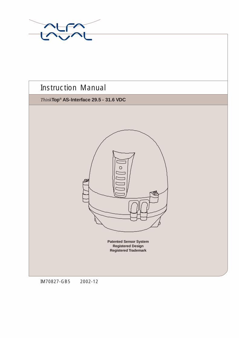
5. Setup diagram5.2 ThinkTop® setup utilising local 'I' and 'II' keys
Notes: I - Scroll across, no change- Notes Requires Key Function
- - Notes Automatic Progress as IndicatedGeneral: 1. Flashing IND means no value set. Steady IND means value set as shown.
2. Default is: Step 2, Type 0 (+/- 5 mm)Step 3-8 disabled
3. Lamp Status Shown in [ ]
4. [D] IND active during set-up.- Flashing in step 1,- Steady in all other steps.or during operations, error condition- Steady showing hardware fault- Flashing showing software fault
5. Timeout: A 60 second time-out is started as soon as any button(s) are released.If no button is pressed during the time-out time, go to normal condition (cancel & exit).
6. SRC/ARC valves: Self-adjust (step 7) must be activated. If you choose NOT to use theself-adjustment programme, Alfa Laval recommends to use the valve type 4 (step 2), instead oftype 1 (bigger tolerances).
EnterEnterEnterEnterEnterSet-up SequenceSet-up SequenceSet-up SequenceSet-up SequenceSet-up Sequence
IIIII
LED D steady,then flashing
Actuate theActuate theActuate theActuate theActuate thevalve tovalve tovalve tovalve tovalve to
open positionopen positionopen positionopen positionopen position
Actuate theActuate theActuate theActuate theActuate thevalve tovalve tovalve tovalve tovalve to
upper seat liftupper seat liftupper seat liftupper seat liftupper seat lift
Actuate theActuate theActuate theActuate theActuate thevalve tovalve tovalve tovalve tovalve to
lower seat liftlower seat liftlower seat liftlower seat liftlower seat lift
Set Open PositionSet Open PositionSet Open PositionSet Open PositionSet Open Position
IIIII BypassBypassBypassBypassBypassMove to next step
IIIIIIIIII Store PositionStore PositionStore PositionStore PositionStore Position
IIIIIIIIII Disable functionDisable functionDisable functionDisable functionDisable function(LED B flashing) Press IPress IPress IPress IPress I
to bypassto bypassto bypassto bypassto bypassmove tomove tomove tomove tomove tonext stepnext stepnext stepnext stepnext step
Set Upper Seat LiftSet Upper Seat LiftSet Upper Seat LiftSet Upper Seat LiftSet Upper Seat Lift
IIIII BypassBypassBypassBypassBypassMove to next step
IIIIIIIIII Store PositionStore PositionStore PositionStore PositionStore Position
IIIIIIIIII Disable functionDisable functionDisable functionDisable functionDisable function(LED B flashing) Press IPress IPress IPress IPress I
to bypassto bypassto bypassto bypassto bypassmove tomove tomove tomove tomove tonext stepnext stepnext stepnext stepnext step
Set Lower Seat LiftSet Lower Seat LiftSet Lower Seat LiftSet Lower Seat LiftSet Lower Seat Lift
IIIII BypassBypassBypassBypassBypassMove to next step
IIIIIIIIII Store PositionStore PositionStore PositionStore PositionStore Position
IIIIIIIIII Disable functionDisable functionDisable functionDisable functionDisable function(LED A flashing)
Press IPress IPress IPress IPress I
to bypassto bypassto bypassto bypassto bypassmove tomove tomove tomove tomove tonext stepnext stepnext stepnext stepnext step
LED D, B steadyLED D, B steadyLED D, B steadyLED D, B steadyLED D, B steadyif open position enabled
LED D steadyLED D steadyLED D steadyLED D steadyLED D steady, B flashingB flashingB flashingB flashingB flashingif open position disabled
""""""""""Holdfor 5 s.
""""""""""Holdfor 5 s.
LED D, C, B steadyLED D, C, B steadyLED D, C, B steadyLED D, C, B steadyLED D, C, B steadyif upper seat lift enabled
LED D, C steadyLED D, C steadyLED D, C steadyLED D, C steadyLED D, C steady, B flashing B flashing B flashing B flashing B flashing if upper seat lift disabled
LED D, C, A steadyLED D, C, A steadyLED D, C, A steadyLED D, C, A steadyLED D, C, A steadyif lower seat lift enabled
LED D, C steadyLED D, C steadyLED D, C steadyLED D, C steadyLED D, C steady, A flashingA flashingA flashingA flashingA flashingif lower seat lift disabled
""""""""""Holdfor 5 s.
Step 4Step 4Step 4Step 4Step 4 Step 5Step 5Step 5Step 5Step 5 Step 6Step 6Step 6Step 6Step 6
See oppositeSee oppositeSee oppositeSee oppositeSee oppositepagepagepagepagepage
See opposite pageSee opposite pageSee opposite pageSee opposite pageSee opposite page
See opposite pageSee opposite pageSee opposite pageSee opposite pageSee opposite page
See opposite pageSee opposite pageSee opposite pageSee opposite pageSee opposite page
LED B "Open valve" (Yellow)
IR-Receiver
LED D "Setup/Internal fault" (Red)
LED C "Seat-lift 1/2" (Yellow)
LED E "Solenoid valves" (Green)
LED F "Maintenance" (Orange)
LED A "Closed valve" (Yellow)
ThinkTop® Visual Indications LED Indications
23
5. Setup diagram 5.2 ThinkTop® setup utilising local 'I' and 'II' keys
Press IPress IPress IPress IPress I
to acceptto acceptto acceptto acceptto acceptselectionselectionselectionselectionselection
Actuate the valveActuate the valveActuate the valveActuate the valveActuate the valvet ot ot ot ot o
closed positionclosed positionclosed positionclosed positionclosed position
Accept SettingsAccept SettingsAccept SettingsAccept SettingsAccept Settings
IIIII Restart set-up sequenceRestart set-up sequenceRestart set-up sequenceRestart set-up sequenceRestart set-up sequence
IIIIIIIIII Save & ExitSave & ExitSave & ExitSave & ExitSave & Exitchanges acceptedchanges acceptedchanges acceptedchanges acceptedchanges accepted(Set Up/Fault steady, briefly)
IIIIIIIIII ExitExitExitExitExitno changes acceptedno changes acceptedno changes acceptedno changes acceptedno changes accepted
""""""""""Holdfor 5 s.
Set V Set V Set V Set V Set Valve Talve Talve Talve Talve Typeypeypeypeype
IIIII BypassBypassBypassBypassBypassMove to next step
IIIIIIIIII SRC/ARC, Series 700SRC/ARC, Series 700SRC/ARC, Series 700SRC/ARC, Series 700SRC/ARC, Series 700(LED C steady)
II*II*II*II*II* LKB (LKLA-T)LKB (LKLA-T)LKB (LKLA-T)LKB (LKLA-T)LKB (LKLA-T)(LED C, E steady)
II*II*II*II*II* Unique, AMP, AMP, AMP, AMP, AMP, SRC-PV, SRC-PV, SRC-PV, SRC-PV, SRC-PV,,,,,SMP-SC Spillage-FreeSMP-SC Spillage-FreeSMP-SC Spillage-FreeSMP-SC Spillage-FreeSMP-SC Spillage-Free(LED C, E, F steady)
II*II*II*II*II* SMP-SC, SMP-TO,SMP-SC, SMP-TO,SMP-SC, SMP-TO,SMP-SC, SMP-TO,SMP-SC, SMP-TO,SMP-BC, SMP-BCA, SBVSMP-BC, SMP-BCA, SBVSMP-BC, SMP-BCA, SBVSMP-BC, SMP-BCA, SBVSMP-BC, SMP-BCA, SBV(LED C, E, F, A steady)
IIIIIIIIII Disable functionDisable functionDisable functionDisable functionDisable function(LED C flashing)All Parameters SetAll Parameters SetAll Parameters SetAll Parameters SetAll Parameters SetTTTTTo Defaulto Defaulto Defaulto Defaulto Default or MH valve,or MH valve,or MH valve,or MH valve,or MH valve, SMP-EC** SMP-EC** SMP-EC** SMP-EC** SMP-EC**
Set Closed PositionSet Closed PositionSet Closed PositionSet Closed PositionSet Closed Position
IIIII BypassBypassBypassBypassBypassMove to next step
IIIIIIIIII Store PositionStore PositionStore PositionStore PositionStore Position
IIIIIIIIII Disable functionDisable functionDisable functionDisable functionDisable function(LED A flashing) Press IPress IPress IPress IPress I
to bypassto bypassto bypassto bypassto bypassmove tomove tomove tomove tomove tonext stepnext stepnext stepnext stepnext step
Set Self AdjustSet Self AdjustSet Self AdjustSet Self AdjustSet Self Adjust
I I I I I BypassBypassBypassBypassBypassMove to next step
SRC/ARC Valves OnlySRC/ARC Valves OnlySRC/ARC Valves OnlySRC/ARC Valves OnlySRC/ARC Valves Only
IIIIIIIIII Associated with closed/open positionRecommended!Recommended!Recommended!Recommended!Recommended!(LED E, A, B steady)
IIIIIIIIII Associated with closedAssociated with closedAssociated with closedAssociated with closedAssociated with closedpositionpositionpositionpositionposition
IIIIIIIIII Associated with openAssociated with openAssociated with openAssociated with openAssociated with openpositionpositionpositionpositionposition
IIIIIIIIII Disable functionDisable functionDisable functionDisable functionDisable function(LED E flashing)
Press IPress IPress IPress IPress I
to acceptto acceptto acceptto acceptto acceptselectionselectionselectionselectionselection
Set-up MaintenanceSet-up MaintenanceSet-up MaintenanceSet-up MaintenanceSet-up Maintenance
I I I I I BypassBypassBypassBypassBypassMove to next step
IIIIIIIIII 90 days90 days90 days90 days90 days(LED F steady)
II*II*II*II*II* 180 days180 days180 days180 days180 days(LED F steady, C flashing)
II*II*II*II*II* 270 days270 days270 days270 days270 days(LED F steady, C, E flashing)
II*II*II*II*II* 360 days360 days360 days360 days360 days(LED F steady, C, E, A flashing)
IIIIIIIIII Disable functionDisable functionDisable functionDisable functionDisable function (LED F flashing)
Set Up/Fault steadySet Up/Fault steadySet Up/Fault steadySet Up/Fault steadySet Up/Fault steady,,,,,Maintenance flashingMaintenance flashingMaintenance flashingMaintenance flashingMaintenance flashingif maintenance disabled
Press IPress IPress IPress IPress I
to acceptto acceptto acceptto acceptto acceptselectionselectionselectionselectionselection
(LED D flashing)
(Make sure to hold "II" forat least 5 sec., all LED willshortly flash)
""""""""""Holdfor 5 s.
LED D, A steadyLED D, A steadyLED D, A steadyLED D, A steadyLED D, A steadyif closed position enabled
LED D steadyLED D steadyLED D steadyLED D steadyLED D steady, A flashingA flashingA flashingA flashingA flashing if closed position disabled
""""""""""Holdfor 5 s.
""""""""""Holdfor 5 s.
LED D steadyLED D steadyLED D steadyLED D steadyLED D steady, E flashing, E flashing, E flashing, E flashing, E flashingif self adjust disabled
""""""""""Holdfor 5 s.
LED D steadyLED D steadyLED D steadyLED D steadyLED D steady,,,,,C flashingC flashingC flashingC flashingC flashing
if valve type disabled
* Press "II" again for nextvalve type (Note LED's)
** seat-lift indication not possible.** seat-lift indication not possible.** seat-lift indication not possible.** seat-lift indication not possible.** seat-lift indication not possible.
""""""""""Holdfor 5 s.
Step 1Step 1Step 1Step 1Step 1Step 2Step 2Step 2Step 2Step 2
Step 3Step 3Step 3Step 3Step 3
Step 7Step 7Step 7Step 7Step 7 Step 8Step 8Step 8Step 8Step 8
See oppositeSee oppositeSee oppositeSee oppositeSee oppositepagepagepagepagepage
See opposite pageSee opposite pageSee opposite pageSee opposite pageSee opposite page
See oppositeSee oppositeSee oppositeSee oppositeSee oppositepagepagepagepagepage
See opposite pageSee opposite pageSee opposite pageSee opposite pageSee opposite page
* Press "II" again for nextmaintenance interval(Note LED's) in steps of 3months, max. up to 18 years.

24
6. Fault finding6.1 Fault finding and LEDs
Below is stated the meaning of the LEDs' indications for fault finding in connection with the operation of the ThinkTop®.
Red flashing: Unit in set-up mode or internal software fault.If internal software fault, re-programme unit.
Red steady: Unit in set-up mode or internal hardware fault.If internal hardware fault, check if magnet is in range and check correct wiring.
1. Orange flashing: Time for maintenance has run out.The unit has been self-adjusted into a maintenance alert condition.Valve maintenance is strongly recommended. After maintenance: Disabling ofmaintenance/self-adjustment function is required before setting new position,however, it is strongly recommended to make a complete new set-up after valvemaintenance.
2. Orange steady, yellow flashing (A and/or B): The unit has been self-adjusted into a maintenance alarm condition and the feedback
is lost (a minimum of seal left).Valve maintenance is required. After maintenance: Disabling of the self-adjustmentfunction is required before setting new position, however, it is stronglyrecommended to make a complete new set up after valve maintenance.
NOTE! The maintenance indicator lighting up, and an open or closed lightflashing.....= Note the following:• Self-adjustment programme is only valid for SRC/ARC valves, do not use
the programme for other valve types.• Use tolerance/valve type 1.• In conjunction with valve type change-over; 21, 22, 31 and 32, the open
position must be defined as the upper sensor position (when the magnet isin the highest position).
• A loose top, magnet holder or sensor system can also generate the alert/alarm condition.
• Removing a ThinkTop® with self-adjust activated, will immediately generatean alarm condition! If the ThinkTop® has to be removed, not because of avalve maintenance issue, but for some other reasons, and you want to storethe already adjusted data - disable the self-adjust function before removingthe ThinkTop® and enable it again once the ThinkTop® is back on theactuator.
• After valve maintenance a disabling of the self-adjustment function isrequired before setting a new position, however, it is strongly recommendedto make a complete new set-up (disable all functions in step 2 valve type -and make a complete new set-up).
Red
Orange
Yellow A
Yellow B

25
Yellow steady: Position C (Seat lift 1-2 or external sensors).
Green steady: Solenoid valves activated.
Note! During set-up LED lights have different functions.
6. Fault finding 6.1 Fault finding and LEDs
Yellow steady: Position B (open valve).
Yellow steady: Position A (closed valve).Yellow A
Yellow B
Yellow C
Green E
26
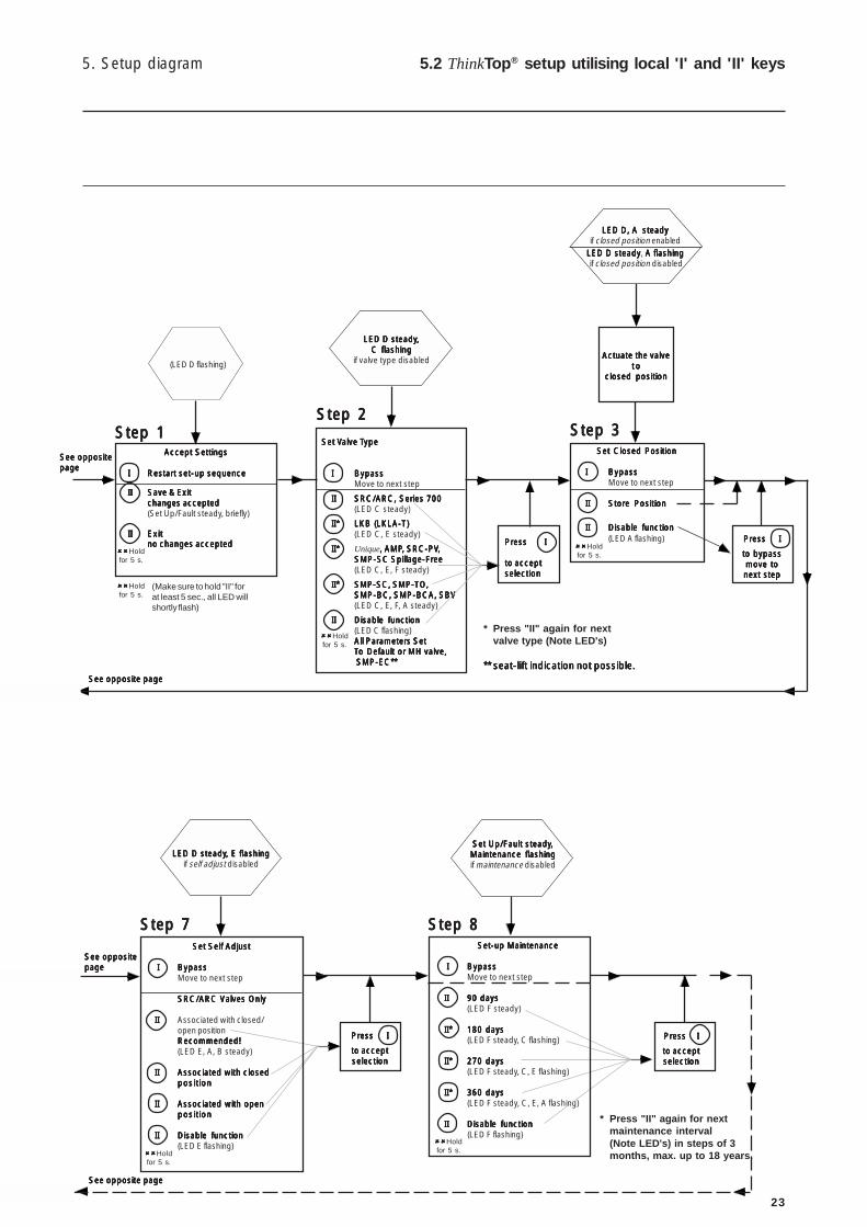
7. Maintenance7.1 Dismantling of ThinkTop®
Step 11. Remove the ThinkTop® from the actuator.2. Pull out X-ring and replace it.
Step 21. Untighten the three screws.2. Pull off the ThinkTop® cover.
Step 31. Untighten screws.2. Remove solenoid valves (up to 3) and replace them with
new ones.
Step 41. To dismantle the adapter (the lower part of the ThinkTop®)
from base (the middle part), unscrew the three screws.2. Turn the lower part a little clockwise and pull.3. Replace adapter if necessary.
Note:Turn banjoconnection!
Study the instructions carefully.Handle scrap correctly.Always keep spare X-rings in stock.

27
7. Maintenance 7.1 Dismantling of ThinkTop®
Step 5To remove the sensor unit untighten screw and pull out thesensor unit.
Study the instructions carefully.Handle scrap correctly.Always keep spare X-rings in stock.
28
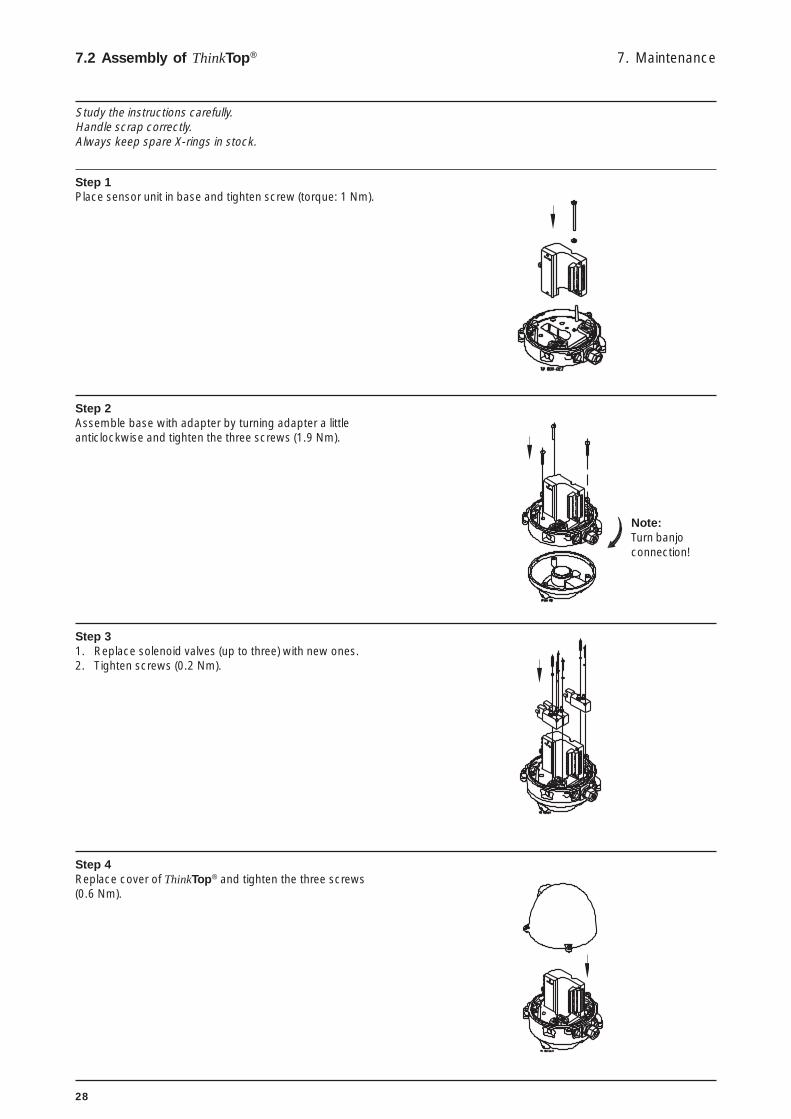
7. Maintenance7.2 Assembly of ThinkTop®
Step 1Place sensor unit in base and tighten screw (torque: 1 Nm).
Step 2Assemble base with adapter by turning adapter a littleanticlockwise and tighten the three screws (1.9 Nm).
Step 31. Replace solenoid valves (up to three) with new ones.2. Tighten screws (0.2 Nm).
Step 4Replace cover of ThinkTop® and tighten the three screws(0.6 Nm).
Note:Turn banjoconnection!
Study the instructions carefully.Handle scrap correctly.Always keep spare X-rings in stock.

29
7. Maintenance 7.2 Assembly of ThinkTop®
Step 51. Replace X-ring.2. Mount the ThinkTop® on actuator.
Study the instructions carefully.Handle scrap correctly.Always keep spare X-rings in stock.

30
Installation onair actuators:
Step 11. Remove the cover by loosening the three cross recess
screws.2. Separate the adapter from the base by loosening the three
recess screws on top of the base.
7. Maintenance7.3 Dismantling and assembly of Series 700 valves
Step 21. Fit air fittings on actuator.2. Position packing retainer in recess on actuator top.3. Fit counter nut and indicator (magnet) on actuator rod.
Engage approx. ¼” thread. Tighten counter nut andindicator with two wrenches.
Step 31. Place the two O-rings in the grooves in the bottom of the
adapter. Then place the adapter on the actuator top. Thesmall O-ring must be positioned over the air hole on theactuator.
2. Fasten the adapter with the four 5/16” Allen screws.
Step 4Mount the base on the adapter in the position needed (can berotated 120° in both directions). Note that one of the screwtowers on the adapter has a guide recess (see ! on drawing).
!
Study the instructions carefully.Handle scrap correctly.Always keep spare X-rings in stock.

31

32
The drawing and the parts list include all items.
Parts List
Pos. Denomination
1a Shell1b Shell2 O-ring, NBR3 Screw4 Washer5 Sensor unit6 Solenoid valve7 PT screw8 Base9 O-ring, NBR10 Air fittings11 Blow-off valve12 Thread plug, PG713 Cable gland, PG11 4-10 mm14 Pressure control valve15 Adapter16 O-ring17 O-ring18 Allen screw19 Special X-ring20a Indication pin20b Indication pin21 O-ring, EPDM23 2 m. ASI drop cable (2 x 0.5 mm2)
with flat cable connector24 Air fitting incl. O-ring
8.1 ThinkTop® AS-Interface 29.5-31.6 VDC 8. Parts list
Spare Parts
Denomination Item number
Sensor unit AS-Interface 29.5-31.6 VDC .. 9612-5627-03
Solenoid valve 3/2, 24 VDC ...................... 9611-99-3324Solenoid valve 5/2, 24 VDC ...................... 9611-99-3327
Air fitting incl. O-ring, Ø6 mm .................... 9611-99-3404Air fitting incl. O-ring, 1/4” ......................... 9611-99-3434
Note! This is the basic design.
The clearance should be approximately:
ø 225 x 250 (SRC NC, SMP-SC/-BC/-TO, Unique,Koltek MH, SBV, AMP)
ø 225 x 320 (SRC NO)ø 225 x 300 (LKB (LKLA-T))
1
2
3
171.
6
ø137
Cle
aran
ce

33
This page shows an exploded drawing of the ThinkTop®. The drawing includes all items of the top unit.
Exploded Drawing
8. Parts list 8.1 ThinkTop® AS-Interface 29.5-31.6 VDC

34
Spare Parts
Denomination 1/4” Air connec.
Sensor unit AS-Interface 29.5-31.6 VDC .. 9612-5627-03
Solenoid valve 3/2, 24 VDC ...................... 9611-99-3324Solenoid valve 5/2, 24 VDC ...................... 9611-99-3327
Air fitting incl. O-ring, 1/4” ......................... 9611-99-3434
The drawing and the parts list include all items.
Parts List
Pos. Denomination
1 Shell3 Screw4 Washer5 Sensor unit6 Solenoid valve7 PT screw8 Base9 O-ring, NBR10 Air fittings11 Blow-off valve12 Thread plug, PG713 Cable gland, PG11 4-10 mm14 Pressure control valve15 Adapter16 O-ring17 O-ring18 Screw19 Retainer20 O-ring21 O-ring, EPDM22 Indicator pin23 Nut25 2 m. ASI drop cable (2 x 0.5 mm2)
with flat cable connector26 Air fitting incl. O-ring
8.2 ThinkTop® Series 700 valves 8. Parts list
Note! This is the basic design.
The clearance should be approximately:
ø 225 x 250 (SRC NC, SMP-SC/-BC/-TO, Unique,Koltek MH, SBV, AMP)
ø 225 x 320 (SRC NO)ø 225 x 300 (LKB (LKLA-T))
1
2
3
171.
6
ø137
Cle
aran
ce

35
This page shows an exploded drawing of the ThinkTop®. The drawing includes all items of the top unit.
Exploded Drawing
8. Parts list 8.2 ThinkTop® Series 700 valves

How to contact Alfa LavalContact details for all countries arecontinually updated on our website.Please visit www.alfalaval.com toaccess the information direct.