Embed Size (px)
Citation preview
Instruction Manual•Operator
KACO blueplanet 2.0 - 5.0 TL1- PSD, internal AFCI

Operator Instructions blueplanet 2.0-5.0TL1 Page 3
Contents
Operator Instructions
1 General Notes ............................................ 4
1.1 About this documentation .................................4
1.2 Design features .......................................................4
2 Safety ......................................................... 6
2.1 Intended use ............................................................ 7
2.2 Protection features ................................................ 7
2.3 Safety standards and regulatory compliance ............................................................... 7
3 Configuration and Operation .................. 8
3.1 Controls ......................................................................8
3.2 Commissioning the inverter .............................. 11
3.3 Menu structure....................................................... 11
3.4 Monitoring the inverter ..................................... 16
3.5 Reset a arc event ................................................... 18
3.6 Performing a software update ........................ 18
General Notes
Page 4 Operator Instructions blueplanet 2.0-5.0TL1
1 General Notes
1.1 About this documentation
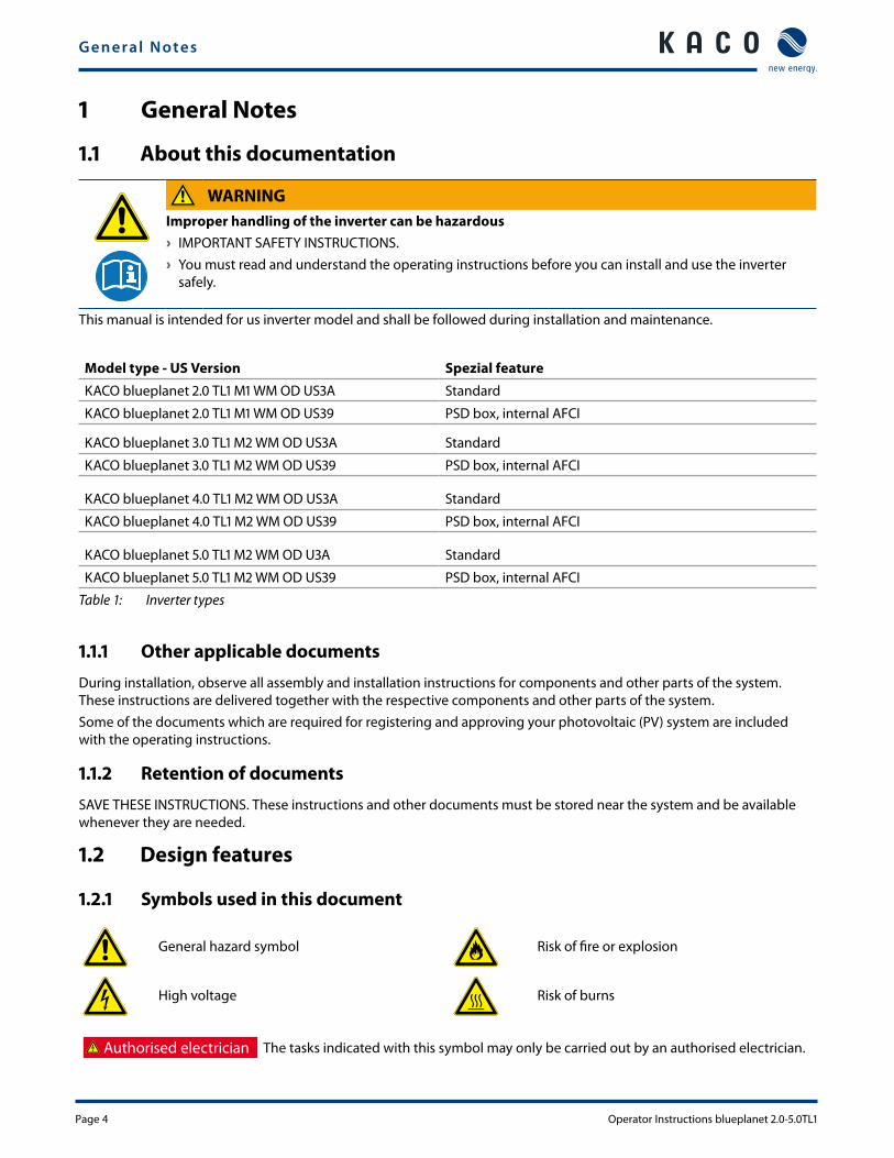
WARNINGImproper handling of the inverter can be hazardous › IMPORTANT SAFETY INSTRUCTIONS. › You must read and understand the operating instructions before you can install and use the inverter
safely.
This manual is intended for us inverter model and shall be followed during installation and maintenance.
Model type - US Version Spezial feature
KACO blueplanet 2.0 TL1 M1 WM OD US3A Standard
KACO blueplanet 2.0 TL1 M1 WM OD US39 PSD box, internal AFCI
KACO blueplanet 3.0 TL1 M2 WM OD US3A Standard
KACO blueplanet 3.0 TL1 M2 WM OD US39 PSD box, internal AFCI
KACO blueplanet 4.0 TL1 M2 WM OD US3A Standard
KACO blueplanet 4.0 TL1 M2 WM OD US39 PSD box, internal AFCI
KACO blueplanet 5.0 TL1 M2 WM OD U3A Standard
KACO blueplanet 5.0 TL1 M2 WM OD US39 PSD box, internal AFCI
Table 1: Inverter types
1.1.1 Other applicable documents
During installation, observe all assembly and installation instructions for components and other parts of the system. These instructions are delivered together with the respective components and other parts of the system.Some of the documents which are required for registering and approving your photovoltaic (PV) system are included with the operating instructions.
1.1.2 Retention of documents
SAVE THESE INSTRUCTIONS. These instructions and other documents must be stored near the system and be available whenever they are needed.
1.2 Design features
1.2.1 Symbols used in this document
General hazard symbol Risk of fire or explosion
High voltage Risk of burns
Authorised electrician The tasks indicated with this symbol may only be carried out by an authorised electrician.
General Notes
Operator Instructions blueplanet 2.0-5.0TL1 Page 5
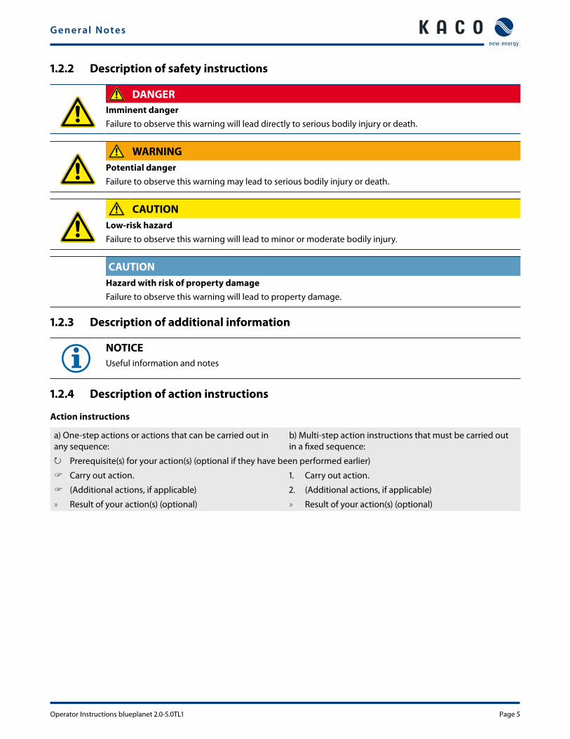
1.2.2 Description of safety instructions
DANGERImminent danger Failure to observe this warning will lead directly to serious bodily injury or death.
WARNINGPotential dangerFailure to observe this warning may lead to serious bodily injury or death.
CAUTIONLow-risk hazardFailure to observe this warning will lead to minor or moderate bodily injury.
CAUTIONHazard with risk of property damageFailure to observe this warning will lead to property damage.
1.2.3 Description of additional information
NOTICEUseful information and notes
1.2.4 Description of action instructions
Action instructions
a) One-step actions or actions that can be carried out in any sequence:
b) Multi-step action instructions that must be carried out in a fixed sequence:
↻ Prerequisite(s) for your action(s) (optional if they have been performed earlier)
" Carry out action. 1. Carry out action.
" (Additional actions, if applicable) 2. (Additional actions, if applicable)
» Result of your action(s) (optional) » Result of your action(s) (optional)
Safety
Page 6 Operator Instructions blueplanet 2.0-5.0TL1
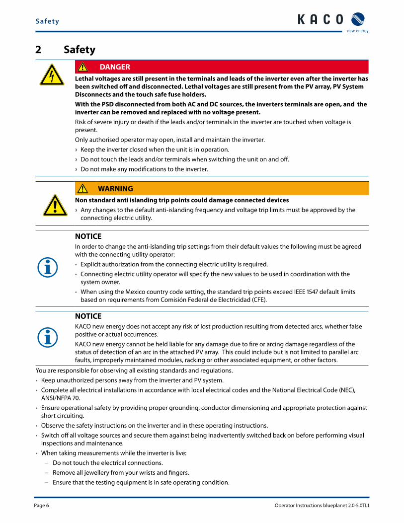
2 SafetyDANGER
Lethal voltages are still present in the terminals and leads of the inverter even after the inverter has been switched off and disconnected. Lethal voltages are still present from the PV array, PV System Disconnects and the touch safe fuse holders.With the PSD disconnected from both AC and DC sources, the inverters terminals are open, and the inverter can be removed and replaced with no voltage present.Risk of severe injury or death if the leads and/or terminals in the inverter are touched when voltage is present.Only authorised operator may open, install and maintain the inverter. › Keep the inverter closed when the unit is in operation. › Do not touch the leads and/or terminals when switching the unit on and off. › Do not make any modifications to the inverter.
WARNINGNon standard anti islanding trip points could damage connected devices › Any changes to the default anti-islanding frequency and voltage trip limits must be approved by the
connecting electric utility.
NOTICEIn order to change the anti-islanding trip settings from their default values the following must be agreed with the connecting utility operator:• Explicit authorization from the connecting electric utility is required.• Connecting electric utility operator will specify the new values to be used in coordination with the
system owner.• When using the Mexico country code setting, the standard trip points exceed IEEE 1547 default limits
based on requirements from Comisión Federal de Electricidad (CFE).
NOTICEKACO new energy does not accept any risk of lost production resulting from detected arcs, whether false positive or actual occurrences.KACO new energy cannot be held liable for any damage due to fire or arcing damage regardless of the status of detection of an arc in the attached PV array. This could include but is not limited to parallel arc faults, improperly maintained modules, racking or other associated equipment, or other factors.
You are responsible for observing all existing standards and regulations. • Keep unauthorized persons away from the inverter and PV system.• Complete all electrical installations in accordance with local electrical codes and the National Electrical Code (NEC),
ANSI/NFPA 70.• Ensure operational safety by providing proper grounding, conductor dimensioning and appropriate protection against
short circuiting.• Observe the safety instructions on the inverter and in these operating instructions.• Switch off all voltage sources and secure them against being inadvertently switched back on before performing visual
inspections and maintenance.• When taking measurements while the inverter is live:
– Do not touch the electrical connections. – Remove all jewellery from your wrists and fingers. – Ensure that the testing equipment is in safe operating condition.
Safety
Operator Instructions blueplanet 2.0-5.0TL1 Page 7
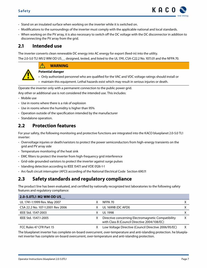
• Stand on an insulated surface when working on the inverter while it is switched on.• Modifications to the surroundings of the inverter must comply with the applicable national and local standards.• When working on the PV array, it is also necessary to switch off the DC voltage with the DC disconnector in addition to
disconnecting the PV array from the grid.
2.1 Intended useThe inverter converts clean renewable DC energy into AC energy for export (feed-in) into the utility.The 2.0-5.0 TL1 M1/2 WM OD US__ designed, tested, and listed to the UL 1741, CSA-C22.2 No. 107.1.01 and the NFPA 70.
WARNINGPotential danger › Only authorized personnel who are qualified for the VAC and VDC voltage ratings should install or › maintain this equipment. Lethal hazards exist which may result in serious injuries or death.
Operate the inverter only with a permanent connection to the public power grid. Any other or additional use is not considered the intended use. This includes: • Mobile use• Use in rooms where there is a risk of explosion• Use in rooms where the humidity is higher than 95%• Operation outside of the specification intended by the manufacturer• Standalone operation.
2.2 Protection featuresFor your safety, the following monitoring and protective functions are integrated into the KACO blueplanet 2.0-5.0 TL1 inverter:• Overvoltage injuries or death/varistors to protect the power semiconductors from high-energy transients on the
grid and PV array side• Temperature monitoring of the heat sink• EMC filters to protect the inverter from high-frequency grid interference• Grid-side grounded varistors to protect the inverter against surge pulses• Islanding detection according to IEEE 1547.1 and VDE 0126-1-1• Arc-fault circuit interrupter (AFCI) according of the National Electrical Code Section 690.11
2.3 Safety standards and regulatory complianceThe product line has been evaluated, and certified by nationally recognized test laboratories to the following safety features and regulatory compliance:
2.0-5.0TL1 M2 WM OD US__UL 1741-1:1999 Rev. May 2007 X NFPA 70 X
CSA 22.2 No. 107-1:2001 Rev 2006 X UL 1699B (DC AFDI) X
IEEE Std. 1547-2003 X UL 1998 X
IEEE Std. 1547.1-2005 X Directive concerning Electromagnetic Compatibility with Class B (Council Directive 2004/108/EC)
X
FCC Rules 47 CFR Part 15 X Low Voltage Directive (Council Directive 2006/95/EC) XThe blueplanet inverter has complete on-board overcurrent, over-temperature and anti-islanding protection. he bluepla-net inverter has complete on-board overcurrent, over-temperature and anti-islanding protection.
Configuration and Operation
Page 8 Operator Instructions blueplanet 2.0-5.0TL1
3 Configuration and Operation
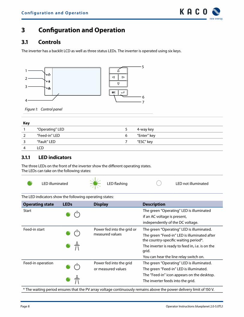
3.1 ControlsThe inverter has a backlit LCD as well as three status LEDs. The inverter is operated using six keys.
1
2
3
4
5
67
Figure 1: Control panel
Key
1 “Operating” LED 5 4-way key
2 “Feed-in” LED 6 “Enter” key
3 “Fault” LED 7 “ESC” key
4 LCD
3.1.1 LED indicators
The three LEDs on the front of the inverter show the different operating states. The LEDs can take on the following states:
LED illuminated LED flashing LED not illuminated
The LED indicators show the following operating states:
Operating state LEDs Display DescriptionStart The green “Operating” LED is illuminated
if an AC voltage is present, independently of the DC voltage.
Feed-in start Power fed into the grid or measured values
The green “Operating” LED is illuminated. The green “Feed-in” LED is illuminated after the country-specific waiting period*. The inverter is ready to feed in, i.e. is on the grid.You can hear the line relay switch on.
Feed-in operation Power fed into the gridor measured values
The green “Operating” LED is illuminated. The green “Feed-in” LED is illuminated.The “Feed-in” icon appears on the desktop.The inverter feeds into the grid.
* The waiting period ensures that the PV array voltage continuously remains above the power delivery limit of 150 V.
Configuration and Operation
Operator Instructions blueplanet 2.0-5.0TL1 Page 9
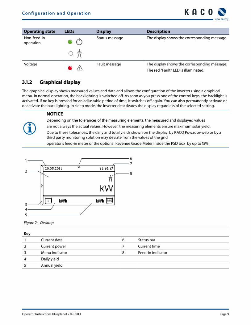
Operating state LEDs Display DescriptionNon-feed-in operation
Status message The display shows the corresponding message.
Voltage Fault message The display shows the corresponding message.The red “Fault” LED is illuminated.
3.1.2 Graphical display
The graphical display shows measured values and data and allows the configuration of the inverter using a graphical menu. In normal operation, the backlighting is switched off. As soon as you press one of the control keys, the backlight is activated. If no key is pressed for an adjustable period of time, it switches off again. You can also permanently activate or deactivate the backlighting. In sleep mode, the inverter deactivates the display regardless of the selected setting.
NOTICEDepending on the tolerances of the measuring elements, the measured and displayed valuesare not always the actual values. However, the measuring elements ensure maximum solar yield.Due to these tolerances, the daily and total yields shown on the display, by KACO Powador-web or by a third party monitoring solution may deviate from the values of the gridoperator’s feed-in meter or the optional Revenue Grade Meter inside the PSD box by up to 15%.
1
2
345
67
8
Figure 2: Desktop
Key
1 Current date 6 Status bar
2 Current power 7 Current time
3 Menu indicator 8 Feed-in indicator
4 Daily yield
5 Annual yield
Configuration and Operation
Page 10 Operator Instructions blueplanet 2.0-5.0TL1
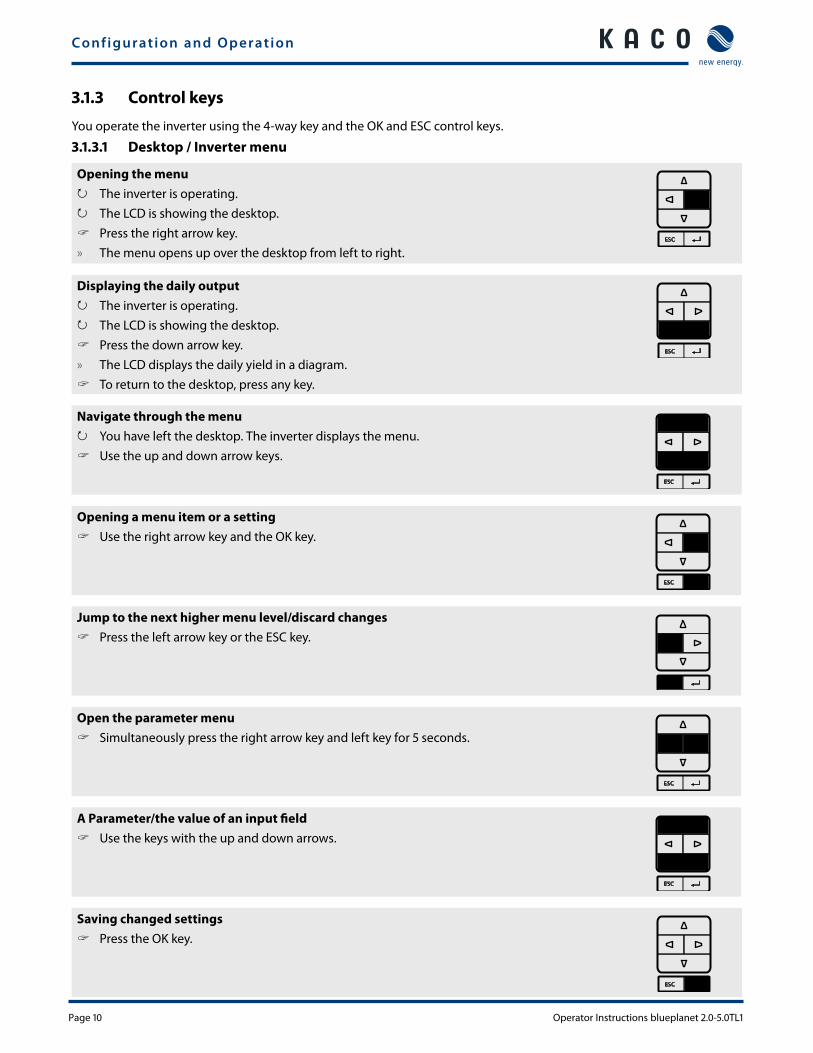
3.1.3 Control keys
You operate the inverter using the 4-way key and the OK and ESC control keys.
3.1.3.1 Desktop / Inverter menu
Opening the menu ↻ The inverter is operating. ↻ The LCD is showing the desktop. " Press the right arrow key.
» The menu opens up over the desktop from left to right.
Displaying the daily output ↻ The inverter is operating. ↻ The LCD is showing the desktop. " Press the down arrow key.
» The LCD displays the daily yield in a diagram. " To return to the desktop, press any key.
Navigate through the menu ↻ You have left the desktop. The inverter displays the menu. " Use the up and down arrow keys.
Opening a menu item or a setting " Use the right arrow key and the OK key.
Jump to the next higher menu level/discard changes " Press the left arrow key or the ESC key.
Open the parameter menu " Simultaneously press the right arrow key and left key for 5 seconds.
A Parameter/the value of an input field " Use the keys with the up and down arrows.
Saving changed settings " Press the OK key.
Configuration and Operation
Operator Instructions blueplanet 2.0-5.0TL1 Page 11
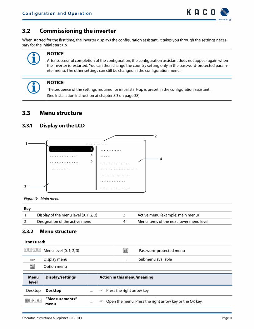
3.2 Commissioning the inverterWhen started for the first time, the inverter displays the configuration assistant. It takes you through the settings neces-sary for the initial start-up.
NOTICEAfter successful completion of the configuration, the configuration assistant does not appear again when the inverter is restarted. You can then change the country setting only in the password-protected param-eter menu. The other settings can still be changed in the configuration menu.
NOTICEThe sequence of the settings required for initial start-up is preset in the configuration assistant. (See Installation Instruction at chapter 8.3 on page 38)
3.3 Menu structure
3.3.1 Display on the LCD
1
3
4
2
Figure 3: Main menu
Key
1 Display of the menu level (0, 1, 2, 3) 3 Active menu (example: main menu)
2 Designation of the active menu 4 Menu items of the next lower menu level
3.3.2 Menu structure
Icons used:
0 1 2 3 Menu level (0, 1, 2, 3) Password-protected menu
Display menu Submenu available
Option menu
Menu level
Display/settings Action in this menu/meaning
Desktop Desktop " Press the right arrow key.
0 1 2 30 “Measurements” menu " Open the menu: Press the right arrow key or the OK key.
Configuration and Operation
Page 12 Operator Instructions blueplanet 2.0-5.0TL1
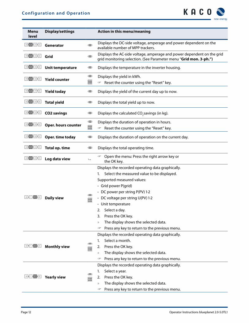
Menu level
Display/settings Action in this menu/meaning
0 1 2 31 Generator Displays the DC-side voltage, amperage and power dependent on the available number of MPP trackers.
0 1 2 31 Grid Displays the AC-side voltage, amperage and power dependent on the grid grid monitoring selection. (See Parameter menu “Grid mon. 3-ph.”)
0 1 2 31 Unit temperature Displays the temperature in the inverter housing.
0 1 2 31 Yield counterDisplays the yield in kWh.
" Reset the counter using the “Reset” key.
0 1 2 31 Yield today Displays the yield of the current day up to now.
0 1 2 31 Total yield Displays the total yield up to now.
0 1 2 31 CO2 savings Displays the calculated CO2savings (in kg).
0 1 2 31 Oper. hours counterDisplays the duration of operation in hours.
" Reset the counter using the “Reset” key.
0 1 2 31 Oper. time today Displays the duration of operation on the current day.
0 1 2 31 Total op. time Displays the total operating time.
0 1 2 31 Log data view " Open the menu: Press the right arrow key or the OK key.
0 1 2 32 Daily view
Displays the recorded operating data graphically.1. Select the measured value to be displayed.Supported measured values:• Grid power P(grid)• DC power per string P(PV) 1-2• DC voltage per string U(PV) 1-2• Unit temperature2. Select a day.3. Press the OK key. » The display shows the selected data.
" Press any key to return to the previous menu.
0 1 2 32 Monthly view
Displays the recorded operating data graphically.1. Select a month.2. Press the OK key. » The display shows the selected data.
" Press any key to return to the previous menu.
0 1 2 32 Yearly view
Displays the recorded operating data graphically.1. Select a year.2. Press the OK key. » The display shows the selected data.
" Press any key to return to the previous menu.
Configuration and Operation
Operator Instructions blueplanet 2.0-5.0TL1 Page 13
Menu level
Display/settings Action in this menu/meaning
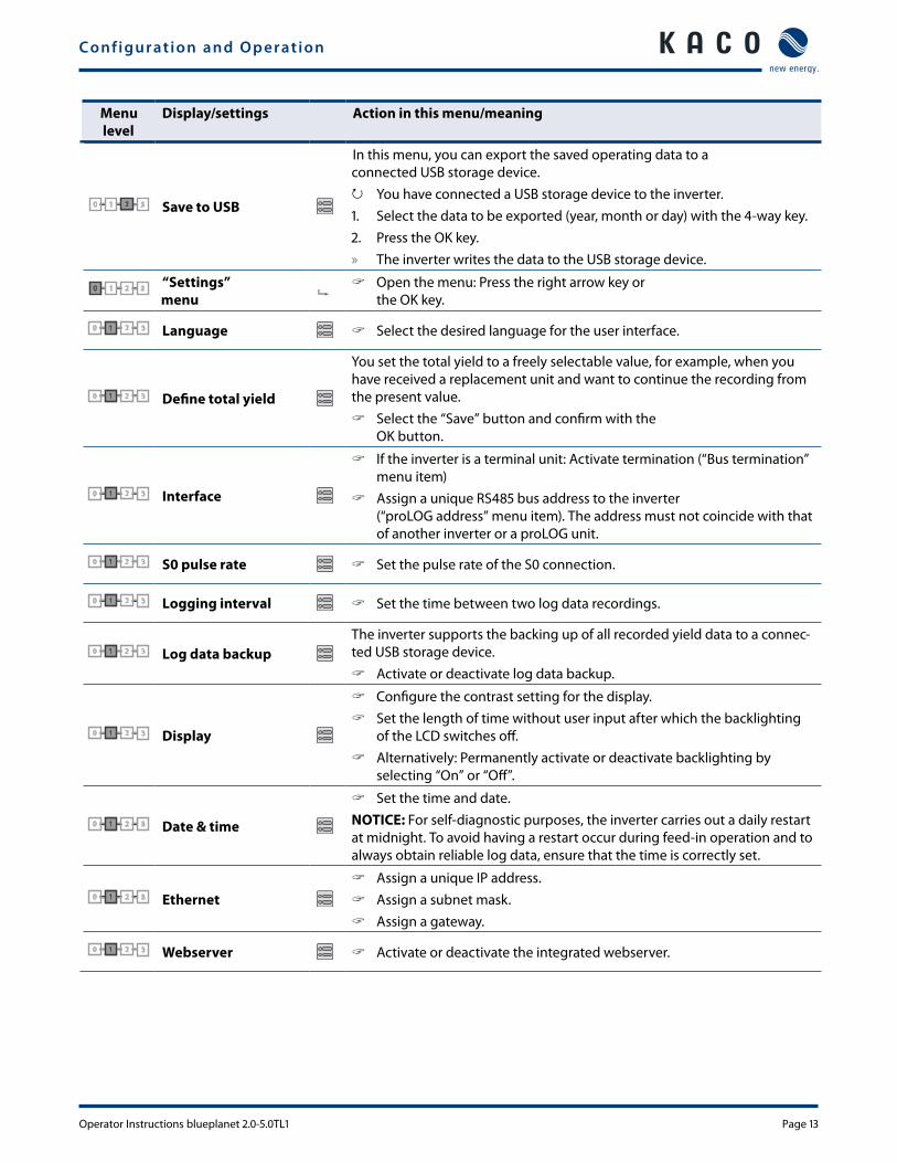
0 1 2 32 Save to USB
In this menu, you can export the saved operating data to a connected USB storage device.
↻ You have connected a USB storage device to the inverter.1. Select the data to be exported (year, month or day) with the 4-way key.2. Press the OK key. » The inverter writes the data to the USB storage device.
0 1 2 30 “Settings” menu
" Open the menu: Press the right arrow key or the OK key.
0 1 2 31 Language " Select the desired language for the user interface.
0 1 2 31 Define total yield
You set the total yield to a freely selectable value, for example, when you have received a replacement unit and want to continue the recording from the present value.
" Select the “Save” button and confirm with the OK button.
0 1 2 31 Interface
" If the inverter is a terminal unit: Activate termination (“Bus termination” menu item)
" Assign a unique RS485 bus address to the inverter (“proLOG address” menu item). The address must not coincide with that of another inverter or a proLOG unit.
0 1 2 31 S0 pulse rate " Set the pulse rate of the S0 connection.
0 1 2 31 Logging interval " Set the time between two log data recordings.
0 1 2 31 Log data backupThe inverter supports the backing up of all recorded yield data to a connec-ted USB storage device.
" Activate or deactivate log data backup.
0 1 2 31 Display
" Configure the contrast setting for the display. " Set the length of time without user input after which the backlighting
of the LCD switches off. " Alternatively: Permanently activate or deactivate backlighting by
selecting “On” or “Off”.
0 1 2 31 Date & time
" Set the time and date.NOTICE: For self-diagnostic purposes, the inverter carries out a daily restart at midnight. To avoid having a restart occur during feed-in operation and to always obtain reliable log data, ensure that the time is correctly set.
0 1 2 31 Ethernet " Assign a unique IP address. " Assign a subnet mask. " Assign a gateway.
0 1 2 31 Webserver " Activate or deactivate the integrated webserver.
Configuration and Operation
Page 14 Operator Instructions blueplanet 2.0-5.0TL1
Menu level
Display/settings Action in this menu/meaning
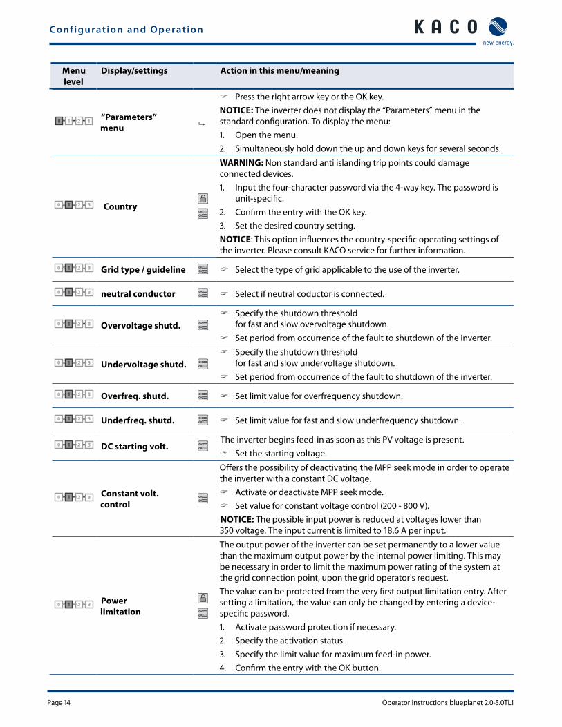
0 1 2 30 “Parameters” menu
" Press the right arrow key or the OK key.NOTICE: The inverter does not display the “Parameters” menu in the standard configuration. To display the menu:1. Open the menu.2. Simultaneously hold down the up and down keys for several seconds.
0 1 2 31 Country
WARNING: Non standard anti islanding trip points could damage connected devices.1. Input the four-character password via the 4-way key. The password is
unit-specific.2. Confirm the entry with the OK key.3. Set the desired country setting.NOTICE: This option influences the country-specific operating settings of the inverter. Please consult KACO service for further information.
0 1 2 31 Grid type / guideline " Select the type of grid applicable to the use of the inverter.
0 1 2 31 neutral conductor " Select if neutral coductor is connected.
0 1 2 31 Overvoltage shutd. " Specify the shutdown threshold
for fast and slow overvoltage shutdown. " Set period from occurrence of the fault to shutdown of the inverter.
0 1 2 31 Undervoltage shutd. " Specify the shutdown threshold
for fast and slow undervoltage shutdown. " Set period from occurrence of the fault to shutdown of the inverter.
0 1 2 31 Overfreq. shutd. " Set limit value for overfrequency shutdown.
0 1 2 31 Underfreq. shutd. " Set limit value for fast and slow underfrequency shutdown.
0 1 2 31 DC starting volt.The inverter begins feed-in as soon as this PV voltage is present.
" Set the starting voltage.
0 1 2 31 Constant volt. control
Offers the possibility of deactivating the MPP seek mode in order to operate the inverter with a constant DC voltage.
" Activate or deactivate MPP seek mode. " Set value for constant voltage control (200 - 800 V).
NOTICE: The possible input power is reduced at voltages lower than 350 voltage. The input current is limited to 18.6 A per input.
0 1 2 31 Power limitation
The output power of the inverter can be set permanently to a lower value than the maximum output power by the internal power limiting. This may be necessary in order to limit the maximum power rating of the system at the grid connection point, upon the grid operator's request.The value can be protected from the very first output limitation entry. After setting a limitation, the value can only be changed by entering a device-specific password. 1. Activate password protection if necessary.2. Specify the activation status.3. Specify the limit value for maximum feed-in power.4. Confirm the entry with the OK button.
Configuration and Operation
Operator Instructions blueplanet 2.0-5.0TL1 Page 15
Menu level
Display/settings Action in this menu/meaning
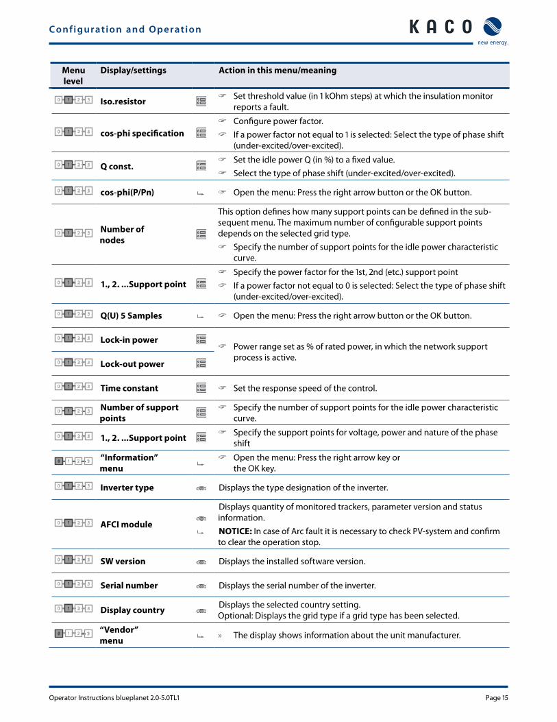
0 1 2 31 Iso.resistor " Set threshold value (in 1 kOhm steps) at which the insulation monitor reports a fault.
0 1 2 31 cos-phi specification " Configure power factor. " If a power factor not equal to 1 is selected: Select the type of phase shift
(under-excited/over-excited).
0 1 2 31 Q const. " Set the idle power Q (in %) to a fixed value. " Select the type of phase shift (under-excited/over-excited).
0 1 2 31 cos-phi(P/Pn) " Open the menu: Press the right arrow button or the OK button.
0 1 2 31 Number of nodes
This option defines how many support points can be defined in the sub-sequent menu. The maximum number of configurable support points depends on the selected grid type.
" Specify the number of support points for the idle power characteristic curve.
0 1 2 31 1., 2. ...Support point " Specify the power factor for the 1st, 2nd (etc.) support point " If a power factor not equal to 0 is selected: Select the type of phase shift
(under-excited/over-excited).
0 1 2 31 Q(U) 5 Samples " Open the menu: Press the right arrow button or the OK button.
0 1 2 31 Lock-in power " Power range set as % of rated power, in which the network support
process is active.0 1 2 31 Lock-out power
0 1 2 31 Time constant " Set the response speed of the control.
0 1 2 31 Number of support points
" Specify the number of support points for the idle power characteristic curve.
0 1 2 31 1., 2. ...Support point " Specify the support points for voltage, power and nature of the phase shift
0 1 2 30 “Information” menu
" Open the menu: Press the right arrow key or the OK key.
0 1 2 31 Inverter type Displays the type designation of the inverter.
0 1 2 31 AFCI module
Displays quantity of monitored trackers, parameter version and status information.NOTICE: In case of Arc fault it is necessary to check PV-system and confirm to clear the operation stop.
0 1 2 31 SW version Displays the installed software version.
0 1 2 31 Serial number Displays the serial number of the inverter.
0 1 2 31 Display country Displays the selected country setting. Optional: Displays the grid type if a grid type has been selected.
0 1 2 30 “Vendor” menu » The display shows information about the unit manufacturer.
Configuration and Operation
Page 16 Operator Instructions blueplanet 2.0-5.0TL1
3.4 Monitoring the inverterThe inverter has an integrated web server. This makes it possible to monitor and record the operating state and yield of your PV system. You can display the recorded data via:• The integrated LCD• The integrated web server using an Internet-capable device connected to the Ethernet interface of the inverterYou can read the recorded data using a storage medium connected to the USB interface of the inverter, e.g. a USB stick.
3.4.1 USB interface
Use an external USB storage device to read operating data saved in the inverter.
3.4.1.1 Reading log data
NOTICEThe USB interface is approved solely for usage with USB flash memories (“USB sticks”). The maximum available current is 100 mA. If a device with a higher power requirement is used, the power supply for the USB interface automatically shuts down to protect the inverter from damage.
Reading log data1. Connect a suitable USB storage device to the USB interface on the underside of the inverter.2. Open the “Log data view” menu.3. Select the “Save to USB” item.4. Select the desired log data using the 4-way key.5. Press the OK key. » The inverter saves the selected log data to the USB storage device.
3.4.2 Web server
The inverter has an integrated web server. After configuration of the network and activation of the web server in the configuration menu, you can open the web server from an Internet browser. The language version of the web site delivered by the browser is dynamically adapted, based on the pre-set language preferences in your Internet browser. If your Internet browser requests a language that is unknown to the inverter, the web server uses the menu language set in the inverter.
3.4.2.1 Setting up the web server
Configuring the Ethernet interface ↻ You have connected the inverter to your network.
1. Open the Settings/Ethernet menu.2. Assign a unique IP address.3. Assign a subnet mask.4. Assign a gateway.5. Save your settings.
Configuration and Operation
Operator Instructions blueplanet 2.0-5.0TL1 Page 17
3.4.2.2 Using the web serverTo avoid problems with incompatibility, use the most recent version of your Internet browser.
NOTICEYou can also access the web server of the inverter via the Internet. To do this, additional settings of your network configuration, particularly your Internet router, are required. Note that communication with the inverter is carried out over an unsecured connection, particularly in the case of a connection over the Internet.
Calling up the web server ↻ Configure the Ethernet interface. ↻ Connect the Ethernet interface.
1. Open an Internet browser.2. In the address field of the Internet browser, enter the IP address of the inverter and call up the site. » The Internet browser displays the start screen of the web server.
After it has been called up, the web server displays information about the inverter as well as the current yield data. The web server supports the display of the following measurement data and yield data:
• Feed-in power • Generator power
• Status • Generator voltage
• Grid power • Unit temperature
• Grid voltage • Grid monitoring modeIn order to display and export yield data, proceed as follows:
Select the display period1. Call up the web server.2. Select the display period by choosing one of the keys: day view, month view, year view or overall view.
Filtering display data (day view only)1. Call up the web server.2. Select the day view.3. To show or hide measured values, select or deselect the corresponding checkboxes in the “Select display” area.
Filtering grid monitoring phase data1. Call up the web server.2. Select the phase for grid monitoring.3. To show or hide measured values, select the menu item “Grid”
Exporting data1. Filter the display data if necessary.2. Select the display period if applicable (day, month, year or overall view). 3. Click the “Export data” key.4. Save the file.
NOTICERegardless of the display data selected in the “Select display” area, an export file always contains all measurement data and yield data available for the selected period.
Configuration and Operation
Page 18 Operator Instructions blueplanet 2.0-5.0TL1
3.5 Reset a arc eventTo reset an arc event change into the “Parameter menu”. The menu item “Arc event” is added in this menu when an arc occurred. After confirming the event the “Arc event” menu item disappears and the inverter starts feeding in again. It is always necessary to reset the event in this way, there is no automatically reset possible.
3.6 Performing a software updateYou can update the software of the inverter to a new version via the integrated USB interface. Us a FAT32-formatted USB stick to do this. Do not use any storage media, such as an external hard disk, with an external power supply.
NOTICEEnsure that the power supply of the AC and DC sides is active. It is only possible to update all components of the inverter to the most current software version in this operating state.
CAUTIONDamage to the inverterThe update can fail if the power supply is interrupted during the update process. Parts of the software or of the inverter itself can then be damaged. » Do not interrupt the DC and AC power supply during the update process.
Preparing for the software update1. Download the software update file from the KACO web site and store it on your hard disk.2. Copy the update file (.KUF) completely onto the USB stick. » Perform software update.
Perform software update. ↻ Prepare for the software update. ↻ Ensure supply of DC and AC power.
1. Connect USB stick to the inverter. » The message “Firmware found. Would you like to load it?” appears on the display.
2. If you would like to perform the update, select the “Yes” button. » The inverter begins the update.
The update can take several minutes. The “Operating” LED flashes during the update process. The inverter may restart several times. The update is completely loaded when the display screen shows the desktop.The inverter then returns to feed-in mode. You can check the success of the update in the menu:
Display software version " Open the Information/SW version menu
» The inverter will display the versions and checksums of the currently loaded software.


KACO new energy (866) 522 6765 [email protected] www.kaco-newenergy.com
The
text
and
figu
res
refle
ct t
he c
urre
nt t
echn
ical
sta
te a
t th
e tim
e of
prin
ting.
Sub
ject
to
tech
nica
l cha
nges
. Er
rors
and
om
issi
ons
exce
pted
. 30
0815
7-03
-151
210