Embed Size (px)
Citation preview
Instruction Manual
IVT-10 / IVT-20
Voltage Tester
EN
1
1. Safety Safety Information To ensure safe operation and service of the Tester, follow these instructions. Failure to observe warnings can result in severe injury or death. - Avoid working alone so assistance can be rendered. If the operators safety can not be guaranteed, the Tester must be removed from service and protected against use. - Prior to usage ensure perfect instrument function (e.g. on known voltage source) before and after the test. - Do not connect the instrument to voltages higher than 750V. - Do not open the battery cover before take off from voltage source. - The safety can no longer be insured if the Tester : • shows obvious damage • does not carry out the desired measurements • has been stored for too long under unfavorable conditions • has been subjected to mechanical stress (i.e. during transport). - All relevant statutory safety regulations must be adhered to when using this instrument. - The Tester may no longer be used if one or several functions fail or if no functionality is indicated or the Tester looks damaged. - When using this Tester, only the handles of the probes may be touched do not touch
the probe tips (metal part). - Do not use the Tester if the Tester is not operating properly or if it is wet. - Use the Tester only as specified in the Instruction card including environmental conditions and the usage in dry environments must be followed or the protection by the Tester might be impaired. - Use extreme caution when working around bare conductors or bus bar. Contact with the conductor could result in an electric shock. - Use caution with voltages above 50V AC rms or 110V DC. These voltages pose a shock hazard.
2
2. Symbols and Features Symbols as marked on the Tester and Instruction manual
Risk of electric shock
See instruction manual
+ or - + DC or –DC measurement
Equipment protected by double or reinforced insulation
Battery
Earth
± AC measurement
Conforms to EU directives
High Voltage Detection
List of features – AC Voltage
– DC Voltage
– Continuity
– Resistance (only on IVT-20)
– Single pole phase test
– Phase rotation of a three-phase mains
– Frequency test (only on IVT-20)
– Auto test
– Probe tip torch
– Drop proof 1 meter
– IP 65 Protection
– Auto Power On/Off
– Selectable probe tips 2/4 mm
3
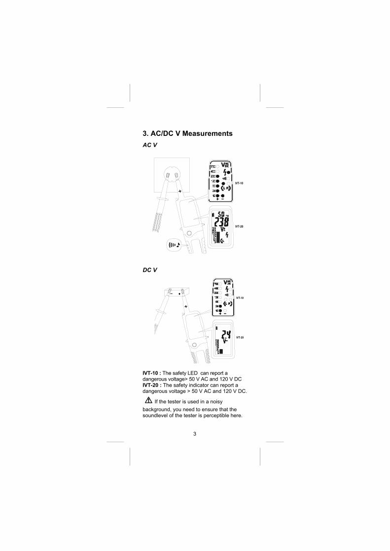
3. AC/DC V Measurements AC V
DC V
IVT-10 : The safety LED can report a dangerous voltage> 50 V AC and 120 V DC IVT-20 : The safety indicator can report a dangerous voltage > 50 V AC and 120 V DC.
If the tester is used in a noisy
background, you need to ensure that the soundlevel of the tester is perceptible here.
4
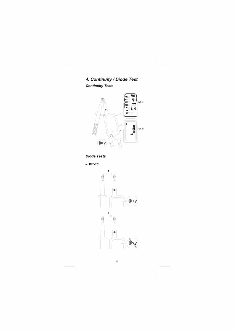
4. Continuity / Diode Test Continuity Tests
Diode Tests – IVT-10
5
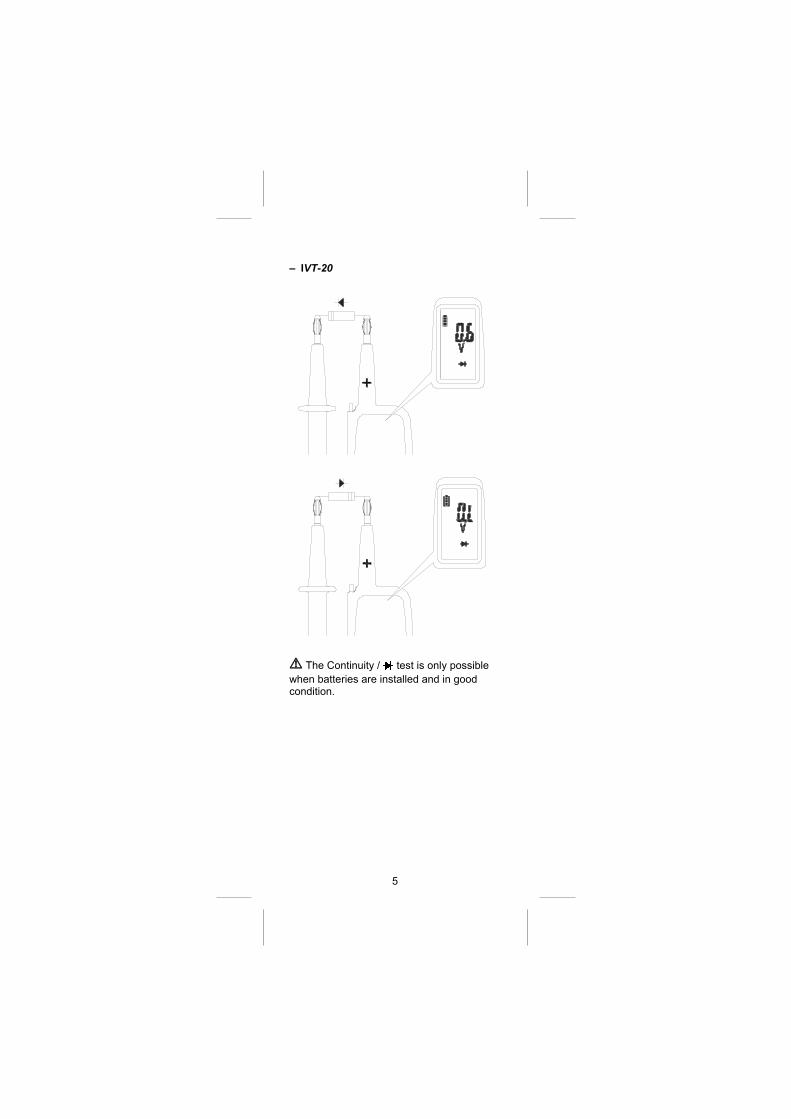
– IVT-20
The Continuity / test is only possible
when batteries are installed and in good condition.
6
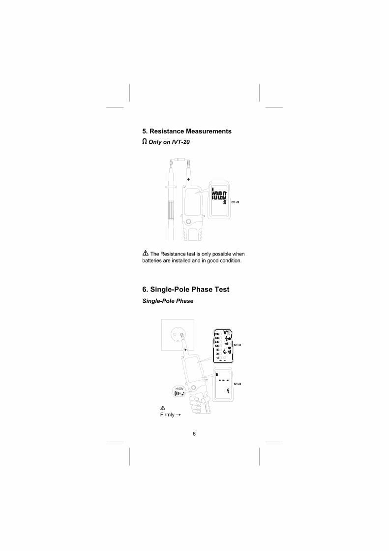
5. Resistance Measurements Only on IVT-20
The Resistance test is only possible when
batteries are installed and in good condition.
6. Single-Pole Phase Test Single-Pole Phase
Firmly →
7
The single-pole phase test is only possible when batteries are installed and in good condition.
The single-pole phase test is not always appropriate for testing whether a circuit is not live. For this purpose, the bipolar test is required.
To determine external conductors during phase tests the display function may be impaired (e.g. for insulating body protection or insulating sites).
Firmly grasp the insulated grips of the Tester probe L2 it is better for increase the sensitivity of single-pole phase test.
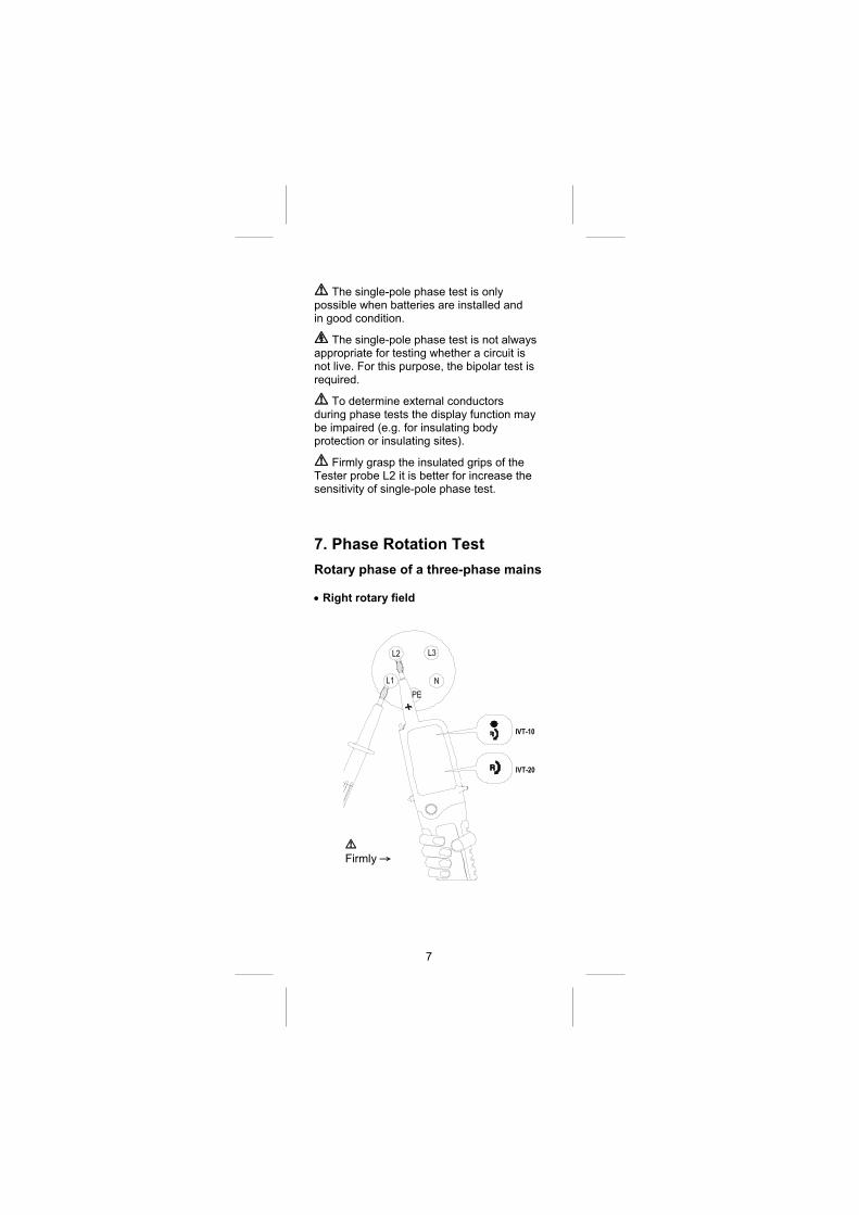
7. Phase Rotation Test Rotary phase of a three-phase mains
Right rotary field
Firmly →
8
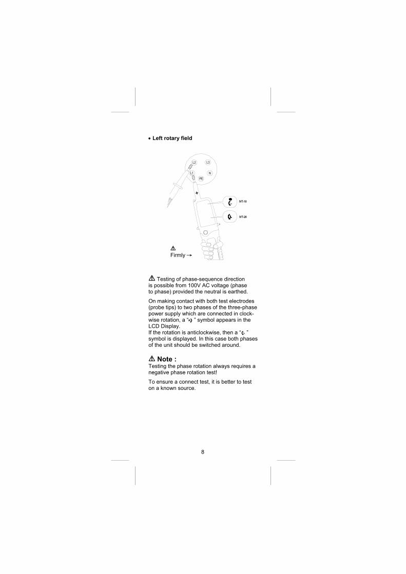
Left rotary field
Testing of phase-sequence direction is possible from 100V AC voltage (phase to phase) provided the neutral is earthed. On making contact with both test electrodes (probe tips) to two phases of the three-phase power supply which are connected in clock-wise rotation, a “B” symbol appears in the LCD Display. If the rotation is anticlockwise, then a “C” symbol is displayed. In this case both phases of the unit should be switched around.
Note : Testing the phase rotation always requires a negative phase rotation test! To ensure a connect test, it is better to test on a known source.
Firmly →
9
Attention : Please ensure that the test electrodes (probe
tips) make good contact with two phases of a
three-phase mains while testing the phase
rotation. For absolute determination of a clock-
wise phase rotation it is necessary to make a
negative phase rotation test after changing the
phases. The indication “B” or “C” can be
affected by unfavorable light conditions, by
protective clothing or in insulated locations. Firmly grasp the insulated grip of the Tester
probe L2, it is better for the sensitivity of the
phase rotation test.
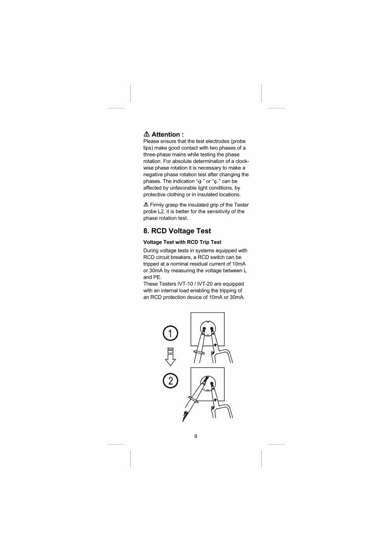
8. RCD Voltage Test Voltage Test with RCD Trip Test During voltage tests in systems equipped with
RCD circuit breakers, a RCD switch can be
tripped at a nominal residual current of 10mA
or 30mA by measuring the voltage between L
and PE.
These Testers IVT-10 / IVT-20 are equipped
with an internal load enabling the tripping of
an RCD protection device of 10mA or 30mA.
10
To avoid RCD tripping, a test has to be
carried out between L and N during approx.
5sec. Immediately afterwards, voltage testing
between L and PE can be carried out without
RCD tripping.
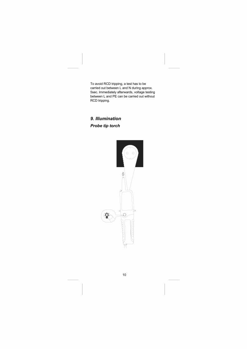
9. Illumination Probe tip torch
11
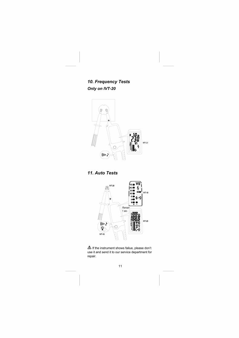
10. Frequency Tests Only on IVT-20
11. Auto Tests
If the instrument shows failue, please don’t
use it and send it to our service department for
repair.
12
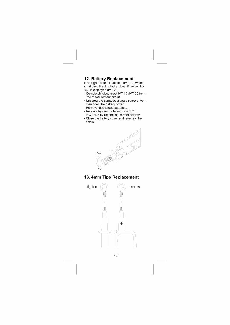
12. Battery Replacement If no signal sound is audible (IVT-10) when short circuiting the test probes, if the symbol “<” is displayed (IVT-20) - Completely disconnect IVT-10 /IVT-20 from the measurement circuit. - Unscrew the screw by a cross screw driver, then open the battery cover. - Remove discharged batteries. - Replace by new batteries, type 1.5V IEC LR03 by respecting correct polarity. - Close the battery cover and re-screw the screw.
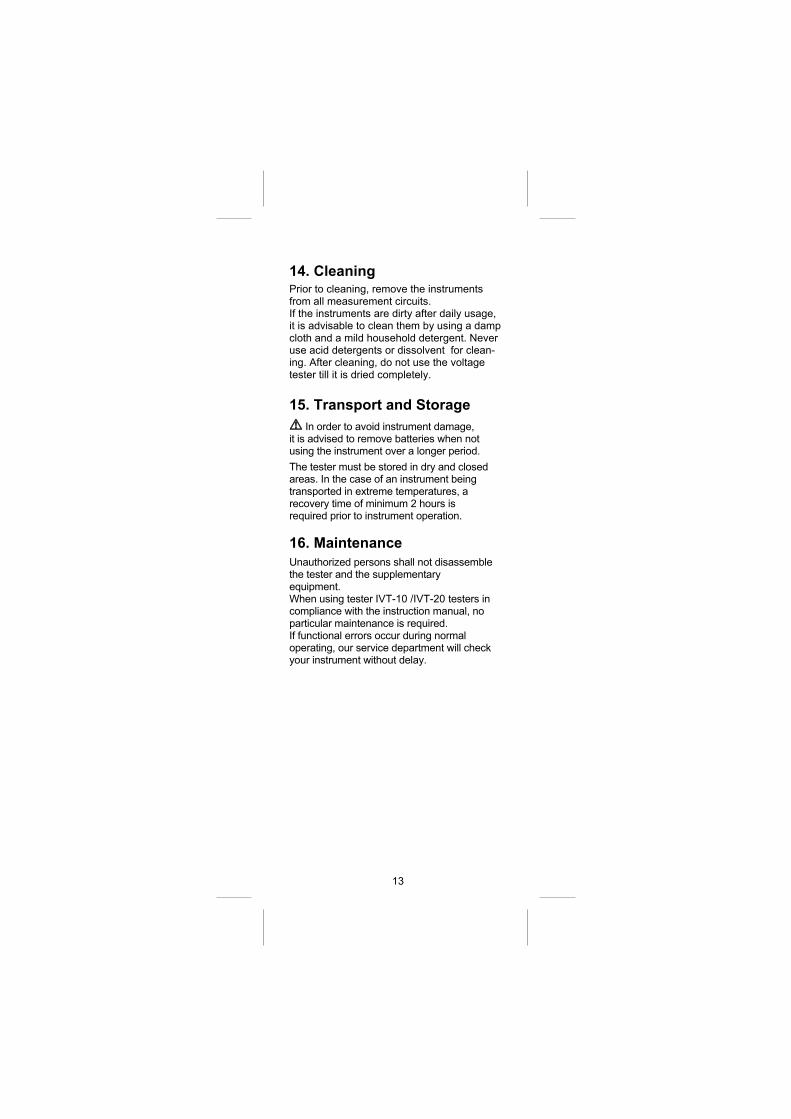
13. 4mm Tips Replacement
13
14. Cleaning Prior to cleaning, remove the instruments from all measurement circuits. If the instruments are dirty after daily usage, it is advisable to clean them by using a damp cloth and a mild household detergent. Never use acid detergents or dissolvent for clean-ing. After cleaning, do not use the voltage tester till it is dried completely.
15. Transport and Storage
In order to avoid instrument damage, it is advised to remove batteries when not using the instrument over a longer period. The tester must be stored in dry and closed areas. In the case of an instrument being transported in extreme temperatures, a recovery time of minimum 2 hours is required prior to instrument operation.
16. Maintenance Unauthorized persons shall not disassemble the tester and the supplementary equipment. When using tester IVT-10 /IVT-20 testers in compliance with the instruction manual, no particular maintenance is required. If functional errors occur during normal operating, our service department will check your instrument without delay.
14
17. Specification
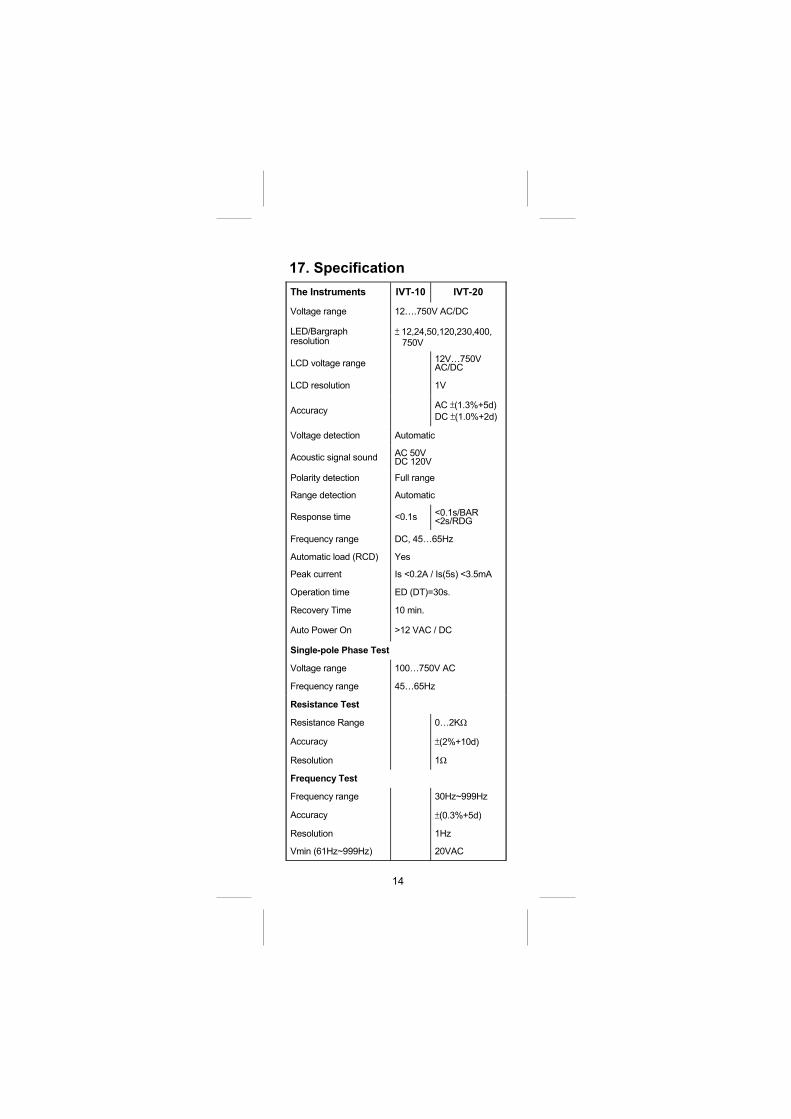
The Instruments IVT-10 IVT-20
Voltage range 12….750V AC/DC
LED/Bargraph resolution
± 12,24,50,120,230,400,
750V
LCD voltage range 12V…750V AC/DC
LCD resolution 1V
Accuracy AC ±(1.3%+5d)
DC ±(1.0%+2d)
Voltage detection Automatic
Acoustic signal sound AC 50V DC 120V
Polarity detection Full range
Range detection Automatic
Response time <0.1s <0.1s/BAR <2s/RDG
Frequency range DC, 45…65Hz
Automatic load (RCD) Yes
Peak current Is <0.2A / Is(5s) <3.5mA
Operation time ED (DT)=30s.
Recovery Time 10 min.
Auto Power On >12 VAC / DC
Single-pole Phase Test
Voltage range 100…750V AC
Frequency range 45…65Hz
Resistance Test
Resistance Range 0…2KΩ
Accuracy ±(2%+10d)
Resolution 1Ω
Frequency Test
Frequency range 30Hz~999Hz
Accuracy ±(0.3%+5d)
Resolution 1Hz
Vmin (61Hz~999Hz) 20VAC
15
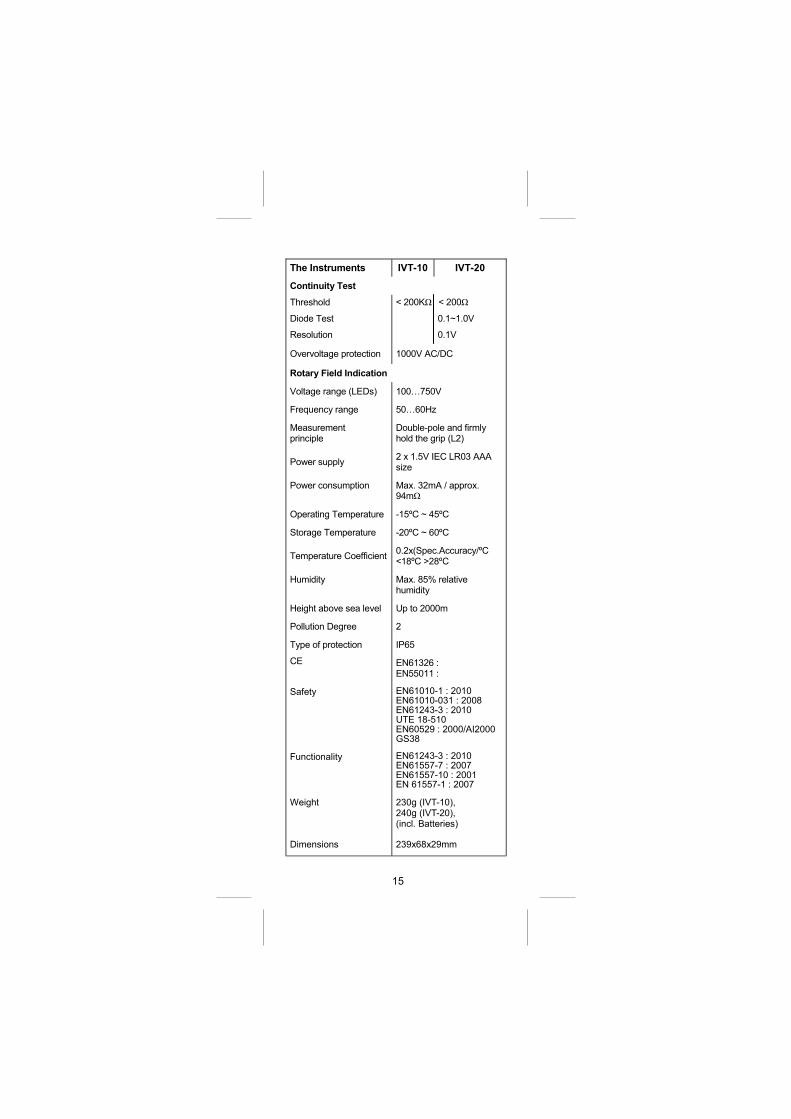
The Instruments IVT-10 IVT-20
Continuity Test
Threshold < 200KΩ < 200Ω
Diode Test 0.1~1.0V
Resolution 0.1V
Overvoltage protection 1000V AC/DC
Rotary Field Indication
Voltage range (LEDs) 100…750V
Frequency range 50…60Hz
Measurement principle
Double-pole and firmly hold the grip (L2)
Power supply 2 x 1.5V IEC LR03 AAA size
Power consumption Max. 32mA / approx. 94mΩ
Operating Temperature -15ºC ~ 45ºC
Storage Temperature -20ºC ~ 60ºC
Temperature Coefficient 0.2x(Spec.Accuracy/ºC <18ºC >28ºC
Humidity Max. 85% relative humidity
Height above sea level Up to 2000m
Pollution Degree 2
Type of protection IP65
CE EN61326 : EN55011 :
Safety EN61010-1 : 2010 EN61010-031 : 2008 EN61243-3 : 2010 UTE 18-510 EN60529 : 2000/AI2000 GS38
Functionality EN61243-3 : 2010 EN61557-7 : 2007 EN61557-10 : 2001 EN 61557-1 : 2007
Weight 230g (IVT-10), 240g (IVT-20), (incl. Batteries)
Dimensions 239x68x29mm
16
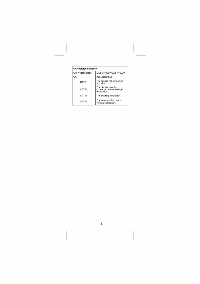
Overvoltage category
Overvoltage class CAT III 1000V/CAT IV 600V
CAT. Application field
CAT I The circuits not connected to mains.
CAT II The circuits directly connected to Low-voltage Installation.
CAT III The building installation
CAT IV The source of the Low –voltage installation.
17
Limited Warranty This meter is warranted to the original
purchaser against defects in material and
workmanship for 3 years from the date of
purchase. During this warranty period,
RS Components will, at its option, replace or
repair the defective unit, subject to verification
of the defect or malfunction.
This warranty does not cover fuses,
disposable batteries, or damage from abuse,
neglect, accident, unauthorized repair,
alteration, contamination, or abnormal
conditions of operation or handling.
Any implied warranties arising out of the sale
of this product, including but not limited to
implied warranties of merchantability and
fitness for a particular purpose, are limited to
the above. RS Components shall not be
liable for loss of use of the instrument or other
incidental or consequential damages,
expenses, or economic loss, or for any claim
or claims for such damage, expense or
economic loss. Some states or countries laws
vary, so the above limitations or exclusions
may not apply to you. For full terms and
conditions, refer to the RS website.
Africa RS Components SA P.O. Box 12182, Vorna Valley, 1686 20 Indianapolis Street, Kyalami Business Park, Kyalami, Midrand South Africa www.rs-components.com Asia RS Components Pte Ltd. 31 Tech Park Crescent Singapore 638040 www.rs-components.com China RS Components Ltd. Suite 23 A-C , East Sea Business Centre Phase 2, No. 618 Yan'an Eastern Road Shanghai, 200001 China www.rs-components.com Europe RS Components Ltd. PO Box 99, Corby, Northants. NN17 9RS United Kingdom www.rs-components.com Japan RS Components Ltd. West Tower (12th Floor), Yokohama Business Park, 134 Godocho, Hodogaya, Yokohama, Kanagawa 240-0005 Japan www.rs-components.com U.S.A Allied Electronics 7151 Jack Newell Blvd. S. Fort Worth, Texas 76118 U.S.A. www.alliedelec.com South America RS Componentes Limitada Av. Pdte. Eduardo Frei M. 6001-71 Centro Empresas El Cortijo Conchali, Santiago, Chile www.rs-components.com