Embed Size (px)
Citation preview
Centrifugal Fan
Original Instruction Manual INSTRUCTION MANUAL
Instructionmanual
2
Figures .................................................................................................................................................................. 3English ................................................................................................................................................................... 7

3
W2 U2 V2 W2 U2 V2 W2 U2 V2 W2 U2 V2
U1 V1 W1 U1 V1 W1 U1 V1 W1
L1 L2 L3
W2 V2U2
U1 U5 V1 V5 W1 W5
W2 W5 U2 U5 V2 V5
U1 V1 W1
U5 W2 V5 U2 V2 W5
W2 W5 U2 U5 V2 V5YY connection 230 V ∆∆ connection 230 V
L1 L2 L3
Y connection 460 V
U1 V1 W1L1 L2 L3
U1 V1 W1U1 V1 W1
L1 L2 L3
∆ connection 460 V
W2 U2 V2W2 W5 U2 U5 V2 V5
U1 V1 W1U1 V1 W1
L1 L2 L3
∆ connection 380 V
Figures1
2
MOUNTING INSTRUCTION Vibration absorber
3
4
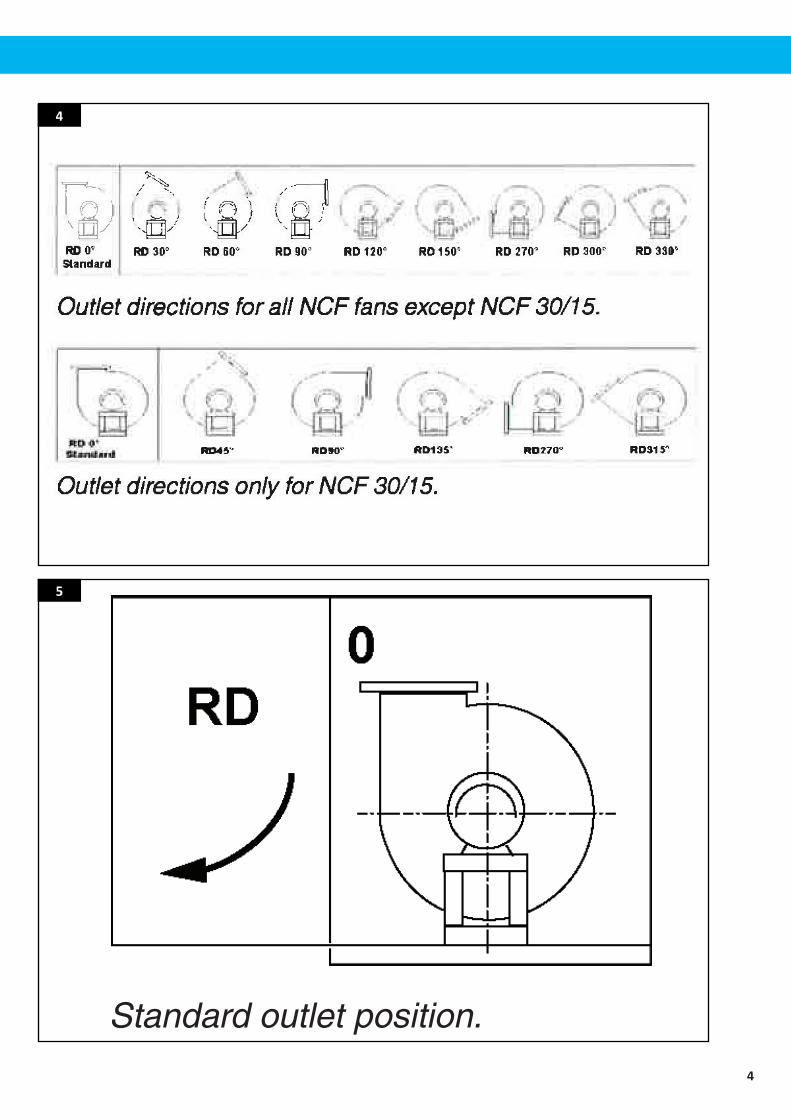
4
Standard outlet position.
5
5
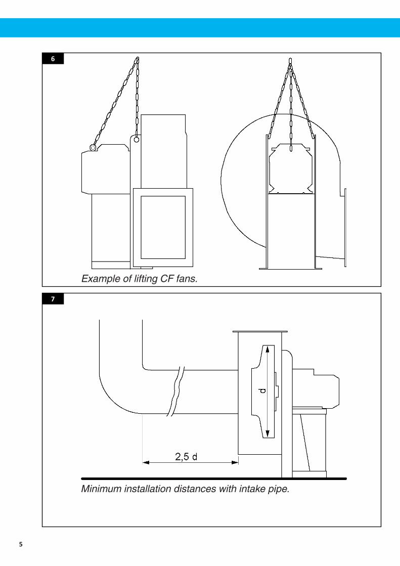
Example of lifting CF fans.
Minimum installation distances with intake pipe.
6
7
6
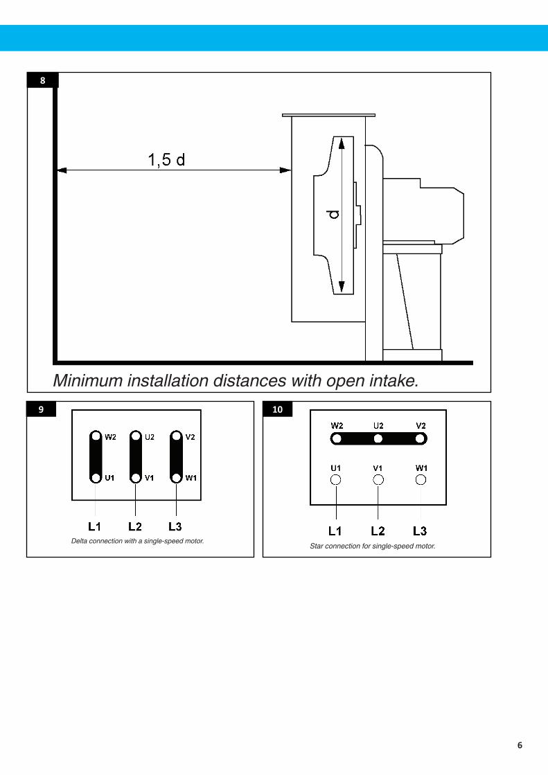
Minimum installation distances with open intake.
Delta connection with a single-speed motor.
8
9
Star connection for single-speed motor.
10
7
EN
Table of contents
EnglishInstructionmanual
1 Preface..............................................................................................................................................................................8
2 Safety.................................................................................................................................................................................82.1 Installation.......................................................................................................................................................82.2 Risksinvolvedinincorrecthandlingoruse...................................................................................92.3 Otherrisksrelatedtofans......................................................................................................................102.4 Specificrisksinvolvedintransportandinstallation.................................................................102.5 Specificrisksinvolvedinfanmaintenance....................................................................................11
3 Description.....................................................................................................................................................................113.1 Technicalspecifications............................................................................................................................11
3.1.1Technicaldata50Hzfans(metric).........................................................................................113.1.2Technicaldata60Hzfans(metric).........................................................................................123.1.3Technicaldata60Hzfans,380V(metric)..........................................................................133.1.4Technicaldata60Hzfans(imperial).....................................................................................13
4 Installation......................................................................................................................................................................144.1 Deliverycheck...............................................................................................................................................144.2 Generalinformation..................................................................................................................................14
4.2.1Fanorientation.................................................................................................................................144.2.2StandardfanoutletpositionforCFfans............................................................................14
4.3 Transportandinstallation.......................................................................................................................144.3.1Transportandlifting......................................................................................................................144.3.2Storageinawarehouse...............................................................................................................154.3.3LiftingCFfans.....................................................................................................................................15
4.4 Installation.......................................................................................................................................................154.4.1Minimumdistancesbetweencomponents.....................................................................164.4.2Connectionstopipes....................................................................................................................164.4.3Electricalconnections...................................................................................................................164.4.4Deltaconnections...........................................................................................................................164.4.5Starconnections..............................................................................................................................16
4.5 Checkstobemadebeforeandafterstarting..............................................................................174.5.1Preliminarychecks..........................................................................................................................174.5.2Checkstobecarriedoutwiththefanrunning...............................................................17
4.6 Malfunctionsanfcauses........................................................................................................................17
5 Maintenance.................................................................................................................................................................185.1 Checkingandcleaningpartsincontactwiththefluid............................................................185.2 Disassembly....................................................................................................................................................19
5.2.1Intakenozzles....................................................................................................................................195.2.2Housing.................................................................................................................................................195.2.3Fanrotor...............................................................................................................................................19
5.3 Technicalenclosures..................................................................................................................................205.4 Spareparts......................................................................................................................................................205.5 Recycling...........................................................................................................................................................21
8
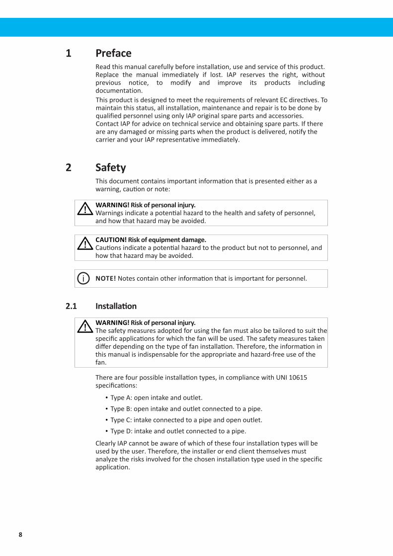
1 PrefaceReadthismanualcarefullybeforeinstallation,useandserviceofthisproduct.Replace the manual immediately if lost. IAP reserves the right, withoutprevious notice, to modify and improve its products includingdocumentation.ThisproductisdesignedtomeettherequirementsofrelevantECdirectives.Tomaintainthisstatus,allinstallation,maintenanceandrepairistobedonebyqualifiedpersonnelusingonlyIAPoriginalsparepartsandaccessories.ContactIAPforadviceontechnicalserviceandobtainingspareparts.Ifthereareanydamagedormissingpartswhentheproductisdelivered,notifythecarrierandyour IAPrepresentativeimmediately.
2 SafetyThisdocumentcontainsimportantinformationthatispresentedeitherasawarning,cautionornote:
WARNING! Risk of personal injury.Warningsindicateapotentialhazardtothehealthandsafetyofpersonnel,andhowthathazardmaybeavoided.
CAUTION! Risk of equipment damage. Cautionsindicateapotentialhazardtotheproductbutnottopersonnel,andhowthathazardmaybeavoided.
NOTE! Notescontainotherinformationthatisimportantforpersonnel.
2.1 Installation
WARNING! Risk of personal injury.Thesafetymeasuresadoptedforusingthefanmustalsobetailoredtosuitthespecificapplicationsforwhichthefanwillbeused.Thesafetymeasurestakendifferdependingonthetypeoffaninstallation.Therefore,theinformationinthismanualisindispensablefortheappropriateandhazard-freeuseofthefan.
Therearefourpossibleinstallationtypes,incompliancewithUNI10615specifications:
• TypeA:openintakeandoutlet.• TypeB:openintakeandoutletconnectedtoapipe.• TypeC:intakeconnectedtoapipeandopenoutlet.• TypeD:intakeandoutletconnectedtoapipe.
ClearlyIAPcannotbeawareofwhichofthesefourinstallationtypeswillbeusedbytheuser.Therefore,theinstallerorendclientthemselvesmustanalyzetherisksinvolvedforthechoseninstallationtypeusedinthespecificapplication.
9
EN
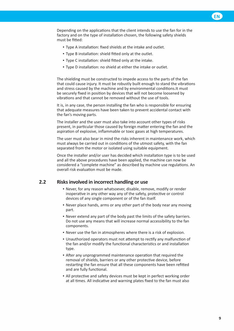
Dependingontheapplicationsthattheclientintendstousethefanforinthefactoryandonthetypeofinstallationchosen,thefollowingsafetyshieldsmustbefitted:
• TypeAinstallation:fixedshieldsattheintakeandoutlet.• TypeBinstallation:shieldfittedonlyattheoutlet.• TypeCinstallation:shieldfittedonlyattheintake.• TypeDinstallation:noshieldateithertheintakeoroutlet.
Theshieldingmustbeconstructedtoimpedeaccesstothepartsofthefanthatcouldcauseinjury.Itmustberobustlybuiltenoughtostandthevibrationsandstresscausedbythemachineandbyenvironmentalconditions.Itmustbesecurelyfixedinpositionbydevicesthatwillnotbecomeloosenedbyvibrationsandthatcannotberemovedwithouttheuseoftools.
Itis,inanycase,thepersoninstallingthefanwhoisresponsibleforensuringthatadequatemeasureshavebeentakentopreventaccidentalcontactwiththefan’smovingparts.
Theinstallerandtheusermustalsotakeintoaccountothertypesofriskspresent,inparticularthosecausedbyforeignmatterenteringthefanandtheaspirationofexplosive,inflammableortoxicgasesathightemperatures.
Theusermustalsobearinmindtherisksinherentinmaintenancework,whichmustalwaysbecarriedoutinconditionsoftheutmostsafety,withthefanseparatedfromthemotororisolatedusingsuitableequipment.
Oncetheinstallerand/oruserhasdecidedwhichinstallationtypeistobeusedandalltheaboveprocedureshavebeenapplied,themachinecannowbeconsidereda“completemachine”asdescribedbymachineuseregulations.Anoverallriskevaluationmustbemade.
2.2 Risks involved in incorrect handling or use• Never,foranyreasonwhatsoever,disable,remove,modifyorrenderinoperativeinanyotherwayanyofthesafety,protectiveorcontroldevicesofanysinglecomponentorofthefanitself.
• Neverplacehands,armsoranyotherpartofthebodynearanymovingpart.
• Neverextendanypartofthebodypastthelimitsofthesafetybarriers.Donotuseanymeansthatwillincreasenormalaccessibilitytothefancomponents.
• Neverusethefaninatmosphereswherethereisariskofexplosion.• Unauthorizedoperatorsmustnotattempttorectifyanymalfunctionofthefanand/ormodifythefunctionalcharacteristicsorandinstallationtype.
• Afteranyunprogrammedmaintenanceoperationthatrequiredtheremovalofshields,barriersoranyotherprotectivedevice,beforerestartingthefanensurethatallthesecomponentshavebeenrefittedandarefullyfunctional.
• Allprotectiveandsafetydevicesmustbekeptinperfectworkingorderatalltimes.Allindicativeandwarningplatesfixedtothefanmustalso
10
bekeptinperfectconditionatalltimesandmustneverberemovedormovedfromtheiroriginalposition.
• Whentroubleshootingforthecauseofanymalfunctionofthefan,ensurethatallprecautionsdescribedinthismanualhavebeentakentopreventpersonalinjuryand/ordamagetoproperty.
• Remembertotighteneveryscrew,boltandlockringofeverycomponentsubjecttoadjustmentormaintenance.
• Beforestartingthefan,ensurethatallsafetydeviceshavebeencorrectlyinstalledandareinperfectworkingorder;iftheaboveisnotthecase,donotstartthefanandinformtheheadofsafetyordepartmentmanagerimmediately.
• TheoperatormustbeequippedwithPersonalprotectionEquipmentsinaccordancewithcurrentlegislation;theuseofbulkyclothingandaccessories(ties,loosesleeves,etc.)isprohibited.
2.3 Other risks related to fansThefollowingisalistofspecifichazardsrelatedtothefan’smechanicalcharacteristics.
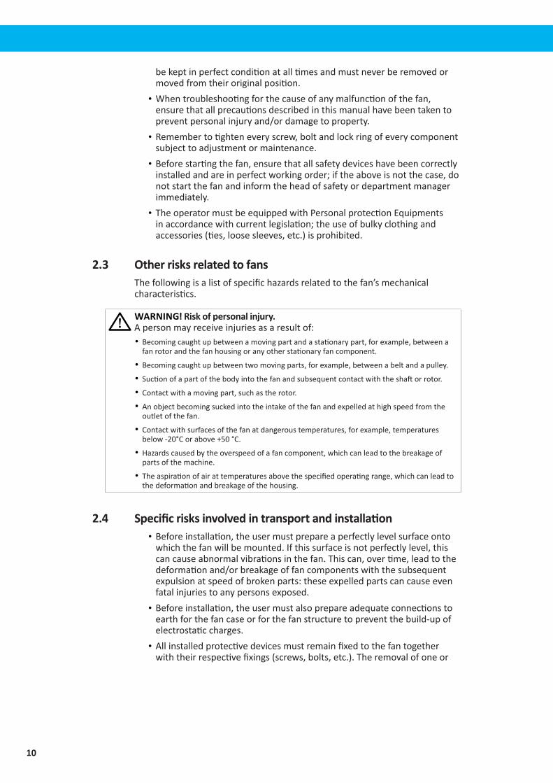
WARNING! Risk of personal injury.Apersonmayreceiveinjuriesasaresultof:• Becomingcaughtupbetweenamovingpartandastationarypart,forexample,betweenafanrotorandthefanhousingoranyotherstationaryfancomponent.
• Becomingcaughtupbetweentwomovingparts,forexample,betweenabeltandapulley.
• Suctionofapartofthebodyintothefanandsubsequentcontactwiththeshaftorrotor.
• Contactwithamovingpart,suchastherotor.
• Anobjectbecomingsuckedintotheintakeofthefanandexpelledathighspeedfromtheoutletofthefan.
• Contactwithsurfacesofthefanatdangeroustemperatures,forexample,temperaturesbelow-20°Corabove+50°C.
• Hazardscausedbytheoverspeedofafancomponent,whichcanleadtothebreakageofpartsofthemachine.
• Theaspirationofairattemperaturesabovethespecifiedoperatingrange,whichcanleadtothedeformationandbreakageofthehousing.
2.4 Specific risks involved in transport and installation• Beforeinstallation,theusermustprepareaperfectlylevelsurfaceontowhichthefanwillbemounted.Ifthissurfaceisnotperfectlylevel,thiscancauseabnormalvibrationsinthefan.Thiscan,overtime,leadtothedeformationand/orbreakageoffancomponentswiththesubsequentexpulsionatspeedofbrokenparts:theseexpelledpartscancauseevenfatalinjuriestoanypersonsexposed.
• Beforeinstallation,theusermustalsoprepareadequateconnectionstoearthforthefancaseorforthefanstructuretopreventthebuild-upofelectrostaticcharges.
• Allinstalledprotectivedevicesmustremainfixedtothefantogetherwiththeirrespectivefixings(screws,bolts,etc.).Theremovalofoneor
11
EN
morefixingmaycompromisethefunctionalityandtightnessofthesafetyshield.
• Initsstandardform,thefanisnotintendedforuseinapotentiallyexplosiveenvironment.
• Theinstallationlocationofthefanmustbekeptcleanatalltimes.Anyeventualoilorwaterspillagesnotcausedbythefanmustberemovedimmediately.
• Theminimuminstallationdistancesspecifiedinthemanualmustalwaysberespectedtoensurecorrectfunctionalitywithoutanyfurtherhazards.Theincorrectpositioningofacomponentcancompromisethefunctionalityofthefan.
2.5 Specific risks involved in fan maintenance• Duringmaintenanceandcleaningofthefanrotor,beparticularcarefuloftherotor.Thiscanleadtopartsofthebodybecomingtrappedandseriouslyinjuredbetweentherotoritselfandfixedpartsofthefanhousing.
• Evenwhenthefanisdisconnectedfromthepowersupply,therotatingpartscanstillturnduetoanyairmovementthroughthefan.Thisairflowmaybenaturalormaybecausedbythecurrentinducedbyanotherfaninstalledelsewhereintheconnectedtubingsystem.Thiscanalsoleadtopartsofthebodybecomingtrappedandseriouslyinjuredbetweentherotoritselfandfixedpartsofthefanhousing.
• Afanmaintenanceprogrammustbedrawnupandfollowedtopreventthemechanicalfailureorbreakageduetowearorinsufficientmaintenance.
3 Description
3.1 Technical specifications
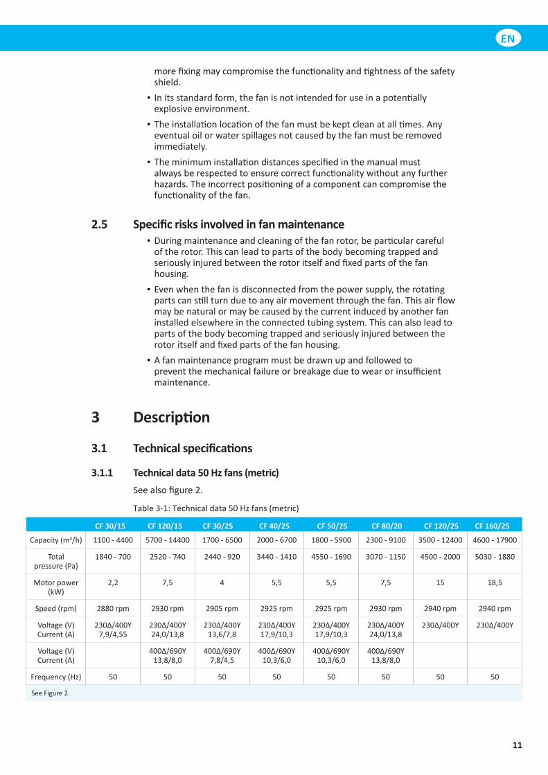
3.1.1 Technical data 50 Hz fans (metric)Seealsofigure2.
Table3-1:Technicaldata50Hzfans(metric)
CF 30/15 CF 120/15 CF 30/25 CF 40/25 CF 50/25 CF 80/20 CF 120/25 CF 160/25
Capacity(m3/h) 1100 - 4400 5700 - 14400 1700 - 6500 2000 - 6700 1800 - 5900 2300 - 9100 3500 - 12400 4600 - 17900
Totalpressure(Pa)
1840 - 700 2520 - 740 2440 - 920 3440 - 1410 4550 - 1690 3070 - 1150 4500 - 2000 5030 - 1880
Motorpower(kW)
2,2 7,5 4 5,5 5,5 7,5 15 18,5
Speed(rpm) 2880rpm 2930rpm 2905rpm 2925rpm 2925rpm 2930rpm 2940rpm 2940rpm
Voltage(V)Current(A)
230Δ/400Y 7,9/4,55
230Δ/400Y24,0/13,8
230Δ/400Y13,6/7,8
230Δ/400Y 17,9/10,3
230Δ/400Y 17,9/10,3
230Δ/400Y 24,0/13,8
230Δ/400Y 230Δ/400Y
Voltage(V)Current(A)
400Δ/690Y 13,8/8,0
400Δ/690Y 7,8/4,5
400Δ/690Y 10,3/6,0
400Δ/690Y 10,3/6,0
400Δ/690Y 13,8/8,0
Frequency(Hz) 50 50 50 50 50 50 50 50
SeeFigure2.
12
CF 30/15 CF 120/15 CF 30/25 CF 40/25 CF 50/25 CF 80/20 CF 120/25 CF 160/25
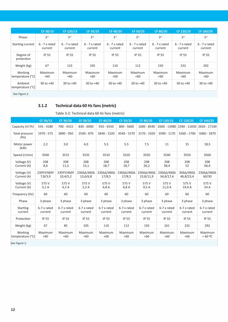
Phase: 3~ 3~ 3~ 3~ 3~ 3~ 3~ 3~
Startingcurrent 6-7xratedcurrent
6-7xratedcurrent
6-7xratedcurrent
6-7xratedcurrent
6-7xratedcurrent
6-7xratedcurrent
6-7xratedcurrent
6-7xratedcurrent
Degreeofprotection
IP55 IP55 IP55 IP55 IP55 IP55 IP55 IP55
Weight(kg) 67 123 105 110 112 150 232 292
Workingtemperature(°C)
Maximum+60
Maximum+60
Maximum+60
Maximum+60
Maximum+60
Maximum+60
Maximum+60
Maximum+60
Ambienttemperature(°C)
30to+40 30to+40 30to+40 30to+40 30to+40 30to+40 30to+40 30to+40
SeeFigure2.
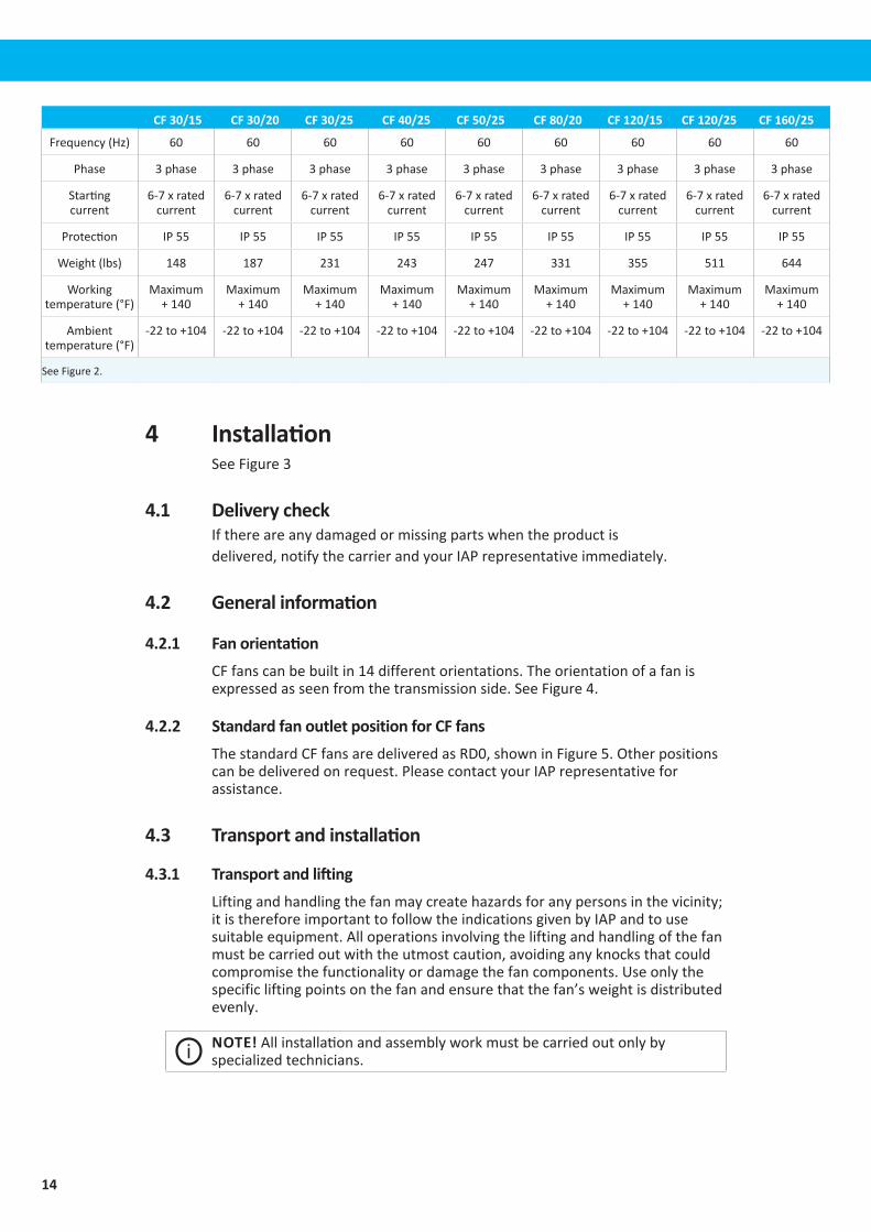
3.1.2 Technical data 60 Hz fans (metric)
Table3-2:Technicaldata60Hzfans(metric)
CF 30/15 CF 30/20 CF 30/25 CF 40/25 CF 50/25 CF 80/20 CF 120/15 CF 120/25 CF 160/25
Capacity(m3/h) 535 - 4180 700 - 4315 830 - 6000 910 - 6550 800 - 5600 1600 - 8540 2600 - 13980 2340 - 11650 2650 - 17140
Totalpressure(Pa)
1970 - 575 2890 - 950 2540 - 870 3640 - 1320 4540 - 1570 3170 - 1020 3590 - 1170 5260 - 1700 5060 - 1870
Motorpower(kW)
2,2 3,0 4,0 5,5 5,5 7,5 11 15 18,5
Speed(r/min) 3500 3515 3535 3510 3520 3550 3540 3550 3560
Voltage(V)Current(A)
208 8,6
208 11,5
208 15,1
208 18,7
208 18,7
208 26,2
208 38,4
208 52
208 66,4
Voltage(V)Current(A)
230YY/460Y 7,8/3,9
230YY/460Y 10,4/5,2
230∆∆/460∆ 13,6/6,8
230∆∆/460∆ 17/8,5
230∆∆/460∆ 17/8,5
230∆∆/460∆ 23,8/11,9
230∆∆/460∆ 34,8/17,4
30∆∆/460∆ 46,8/23,4
230∆∆/460∆ 60/30
Voltage(V)Current(A)
575V 3,1A
575V 4,2A
575V 5,5A
575V 6,8A
575V 6,8A
575V 9,5A
575V 11,0A
575V 19,4A
575V 24A
Frequency(Hz) 60 60 60 60 60 60 60 60 60
Phase 3phase 3phase 3phase 3phase 3phase 3phase 3phase 3phase 3phase
Starting current
6-7xrated current
6-7xrated current
6-7xrated current
6-7xrated current
6-7xrated current
6-7xrated current
6-7xrated current
6-7xrated current
6-7xrated current
Protection IP55 IP55 IP55 IP55 IP55 IP55 IP55 IP55 IP55
Weight(kg) 67 85 105 110 112 150 161 232 292
Working temperature(°C)
Maximum+60
Maximum+60
Maximum+60
Maximum+60
Maximum+60
Maximum+60
Maximum+60
Maximum+60
Maximum +60ºC
SeeFigure2.

13
EN
CF 30/15 CF 30/20 CF 30/25 CF 40/25 CF 50/25 CF 80/20 CF 120/15 CF 120/25 CF 160/25
Ambient temperature(°C)
30to+40 30to+40 30to+40 30to+40 30to+40 30to+40 30to+40 30to+40 -30ºCto +40ºC
SeeFigure2.
3.1.3 Technical data 60 Hz fans, 380 V (metric)
Table3-3:Technicaldata60Hzfans(metric)
CF 30/15 CF 30/20 CF 30/25 CF 40/25 CF 50/25 CF 80/20 CF 120/25 CF 120/25 CF 160/25
Capacity(m3/h) 830 - 6000 910 - 6550 800 - 5600 1600 - 8540 2340 - 11650 2650 - 17140
Totalpressure(Pa)
2540 - 870 3640 - 1320 4540 - 1570 3170 - 1020 5260 - 1700 5060 - 1870
Motorpower(kW)
4,0 5,5 5,5 7,5 15 18,5
Speed(r/min) 3535 3510 3520 3550 3550 3560
Voltage(V)Current(A)
380∆ 8,2
380∆ 10,8
380∆ 10,8
380∆ 14,5
380∆ 27,9
380∆ 34
Frequency(Hz) 60 60 60 60 60 60
Phase 3phase 3phase 3phase 3phase 3phase 3phase
Starting current
6-7xrated current
6-7xrated current
6-7xrated current
6-7xrated current
6-7xrated current
6-7xrated current
Protection IP55 IP55 IP55 IP55 IP55 IP55
Weight(kg) 105 110 112 150 232 292
Working temperature(°C)
Maximum +60
Maximum +60
Maximum +60
Maximum +60
Maximum +60
Maximum+60
Ambient temperature(°C)
-30to+40 -30to+40 -30to+40 -30to+40 -30to+40 -30to+40
SeeFigure2.
3.1.4 Technical data 60 Hz fans (imperial)
Table3-4:Technicaldata60Hzfans(imperial)
CF 30/15 CF 30/20 CF 30/25 CF 40/25 CF 50/25 CF 80/20 CF 120/15 CF 120/25 CF 160/25
Capacity(cfm) 315 - 2466
410 - 2540
490 - 3535
535 - 3855
470 - 3300
940 - 5025
1530 - 8230
1375 - 6855
1560 - 10090
Totalpressure (inw.g.)
7.9-2.3 11.6-3.8 inw.g
10.2-3.5 14.6-5.3 18.2-6.3 12.7-4.1 14.4-4.7 21.1-6.8 20.3-7.5
Motorpower(hp)
3.0hp 4.0hp 5.5hp 7.5hp 7.5hp 10hp 15hp 20hp 25hp
Speed(r/min) 3500r/min 3515r/min 3535r/min 3510r/min 3520r/min 3550r/min 3540r/min 3550r/min 3560r/min
Voltage(V)Current(A)
208 8.6
208 11.5
208 15.1
208 18.7
208 18.7
208 26.2
208 38.4
208 52
208 66.4
Voltage(V)Current(A)
230YY/460Y 7.8/3.9
230YY/460Y 10.4/5.2
230ΔΔ/460Δ 13.6/6.8
230ΔΔ/460Δ 17/8.5
230ΔΔ/460Δ 17/8.5
230ΔΔ/460Δ 23.8/11.9
230ΔΔ/460Δ 34.8/17.4
230ΔΔ/460Δ 46.8/23.4
230ΔΔ/460Δ 60/30
Voltage(V)Current(A)
575V 3.1A
575V 4.2A
575V 5.5A
575V 6.8A
575V 6.8A
575V 9.5A
575V 11.0A
575V 19.4A
575V 24A
SeeFigure2.
14
CF 30/15 CF 30/20 CF 30/25 CF 40/25 CF 50/25 CF 80/20 CF 120/15 CF 120/25 CF 160/25
Frequency(Hz) 60 60 60 60 60 60 60 60 60
Phase 3phase 3phase 3phase 3phase 3phase 3phase 3phase 3phase 3phase
Starting current
6-7xrated current
6-7xrated current
6-7xrated current
6-7xrated current
6-7xrated current
6-7xrated current
6-7xrated current
6-7xrated current
6-7xrated current
Protection IP55 IP55 IP55 IP55 IP55 IP55 IP55 IP55 IP55
Weight(lbs) 148 187 231 243 247 331 355 511 644
Working temperature(°F)
Maximum +140
Maximum +140
Maximum +140
Maximum +140
Maximum +140
Maximum +140
Maximum +140
Maximum +140
Maximum +140
Ambient temperature(°F)
-22to+104 -22to+104 -22to+104 -22to+104 -22to+104 -22to+104 -22to+104 -22to+104 -22to+104
SeeFigure2.
4 InstallationSeeFigure3
4.1 Delivery checkIfthereareanydamagedormissingpartswhentheproductisdelivered,notifythecarrierandyour IAPrepresentativeimmediately.
4.2 General information
4.2.1 Fan orientationCFfanscanbebuiltin14differentorientations.Theorientationofafanisexpressedasseenfromthetransmissionside.SeeFigure4.
4.2.2 Standard fan outlet position for CF fansThestandardCFfansaredeliveredasRD0,showninFigure5.Otherpositionscanbedeliveredonrequest.PleasecontactyourIAP representativeforassistance.
4.3 Transport and installation
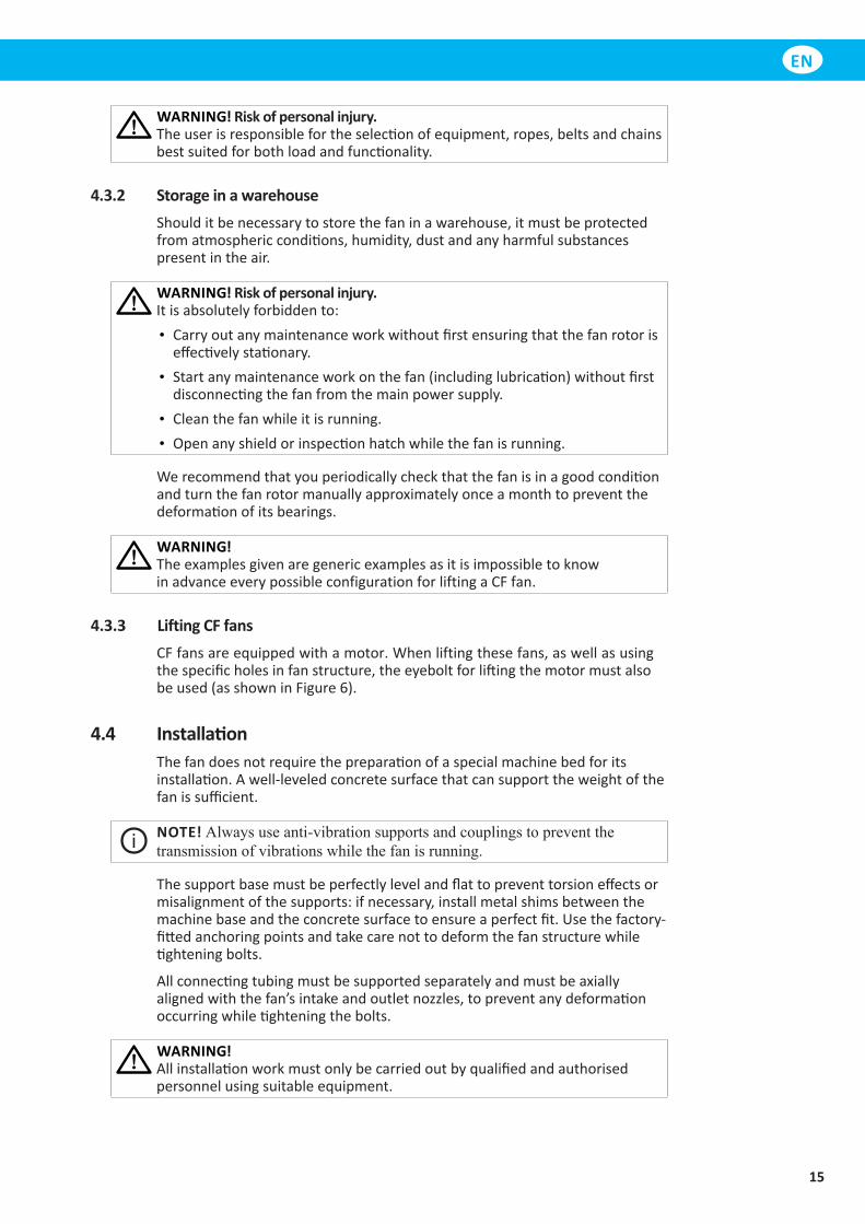
4.3.1 Transport and liftingLiftingandhandlingthefanmaycreatehazardsforanypersonsinthevicinity;itisthereforeimportanttofollowtheindicationsgivenbyIAPandtousesuitableequipment.Alloperationsinvolvingtheliftingandhandlingofthefanmustbecarriedoutwiththeutmostcaution,avoidinganyknocksthatcouldcompromisethefunctionalityordamagethefancomponents.Useonlythespecificliftingpointsonthefanandensurethatthefan’sweightisdistributedevenly.
NOTE! Allinstallationandassemblyworkmustbecarriedoutonlybyspecializedtechnicians.
15
EN
WARNING! Risk of personal injury.Theuserisresponsiblefortheselectionofequipment,ropes,beltsandchainsbestsuitedforbothloadandfunctionality.
4.3.2 Storage in a warehouseShoulditbenecessarytostorethefaninawarehouse,itmustbeprotectedfromatmosphericconditions,humidity,dustandanyharmfulsubstancespresentintheair.
WARNING! Risk of personal injury.Itisabsolutelyforbiddento:• Carryoutanymaintenanceworkwithoutfirstensuringthatthefanrotoriseffectivelystationary.
• Startanymaintenanceworkonthefan(includinglubrication)withoutfirstdisconnectingthefanfromthemainpowersupply.
• Cleanthefanwhileitisrunning.• Openanyshieldorinspectionhatchwhilethefanisrunning.
Werecommendthatyouperiodicallycheckthatthefanisinagoodconditionandturnthefanrotormanuallyapproximatelyonceamonthtopreventthedeformationofitsbearings.
WARNING!TheexamplesgivenaregenericexamplesasitisimpossibletoknowinadvanceeverypossibleconfigurationforliftingaCFfan.
4.3.3 Lifting CF fansCFfansareequippedwithamotor.Whenliftingthesefans,aswellasusingthespecificholesinfanstructure,theeyeboltforliftingthemotormustalsobeused(asshowninFigure6).
4.4 InstallationThefandoesnotrequirethepreparationofaspecialmachinebedforitsinstallation.Awell-leveledconcretesurfacethatcansupporttheweightofthefanissufficient.
NOTE! Alwaysuseanti-vibrationsupportsandcouplingstopreventthetransmissionofvibrationswhilethefanisrunning.
Thesupportbasemustbeperfectlylevelandflattopreventtorsioneffectsormisalignmentofthesupports:ifnecessary,installmetalshimsbetweenthemachinebaseandtheconcretesurfacetoensureaperfectfit.Usethefactory-fittedanchoringpointsandtakecarenottodeformthefanstructurewhiletighteningbolts.
Allconnectingtubingmustbesupportedseparatelyandmustbeaxiallyalignedwiththefan’sintakeandoutletnozzles,topreventanydeformationoccurringwhiletighteningthebolts.
WARNING!Allinstallationworkmustonlybecarriedoutbyqualifiedandauthorisedpersonnelusingsuitableequipment.
16
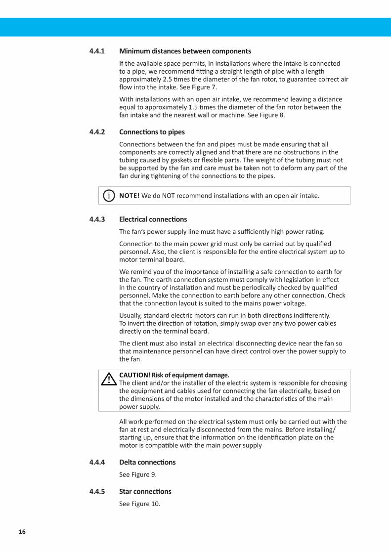
4.4.1 Minimum distances between components Iftheavailablespacepermits,ininstallationswheretheintakeisconnectedtoapipe,werecommendfittingastraightlengthofpipewithalengthapproximately2.5timesthediameterofthefanrotor,toguaranteecorrectairflowintotheintake.SeeFigure7.
Withinstallationswithanopenairintake,werecommendleavingadistanceequaltoapproximately1.5timesthediameterofthefanrotorbetweenthefanintakeandthenearestwallormachine.SeeFigure8.
4.4.2 Connections to pipesConnectionsbetweenthefanandpipesmustbemadeensuringthatallcomponentsarecorrectlyalignedandthattherearenoobstructionsinthetubingcausedbygasketsorflexibleparts.Theweightofthetubingmustnotbesupportedbythefanandcaremustbetakennottodeformanypartofthefanduringtighteningoftheconnectionstothepipes.
NOTE! WedoNOTrecommendinstallationswithanopenairintake.
4.4.3 Electrical connectionsThefan’spowersupplylinemusthaveasufficientlyhighpowerrating.
Connectiontothemainpowergridmustonlybecarriedoutbyqualifiedpersonnel.Also,theclientisresponsiblefortheentireelectricalsystemuptomotorterminalboard.
Weremindyouoftheimportanceofinstallingasafeconnectiontoearthforthefan.Theearthconnectionsystemmustcomplywithlegislationineffectinthecountryofinstallationandmustbeperiodicallycheckedbyqualifiedpersonnel.Maketheconnectiontoearthbeforeanyotherconnection.Checkthattheconnectionlayoutissuitedtothemainspowervoltage.
Usually,standardelectricmotorscanruninbothdirectionsindifferently.Toinvertthedirectionofrotation,simplyswapoveranytwopowercablesdirectlyontheterminalboard.
Theclientmustalsoinstallanelectricaldisconnectingdevicenearthefansothatmaintenancepersonnelcanhavedirectcontroloverthepowersupplytothefan.
CAUTION! Risk of equipment damage. Theclientand/ortheinstalleroftheelectricsystemisresponibleforchoosingtheequipmentandcablesusedforconnectingthefanelectrically,basedonthedimensionsofthemotorinstalledandthecharacteristicsofthemainpowersupply.
Allworkperformedontheelectricalsystemmustonlybecarriedoutwiththefanatrestandelectricallydisconnectedfromthemains.Beforeinstalling/startingup,ensurethattheinformationontheidentificationplateonthemotoriscompatiblewiththemainpowersupply
4.4.4 Delta connectionsSeeFigure9.
4.4.5 Star connectionsSeeFigure10.
17
EN
4.5 Checks to be made before and after starting
4.5.1 Preliminary checks
WARNING! Risk of personal injury!Preliminarychecksmustonlybeperformedwiththefanatrestanddisconnectedfromthepowersupply.
Whenstartingthefanforthefirsttime,thefollowingpreliminarychecksarenecessary:
• Checkthatallboltsarecorrectlytightened(rotor,supports,foundationbolts,andtransmissioncomponents).
• Checkthelubricationofthefanandmotorbearings;ifnecessary,regrease(seeChapter5. Maintenance).
• Checkthatallrotatingpartscanturnfreely.• Checkthattherearenotforeignobjectsinsidethefan.• Checkthatthefanturnsinthecorrectdirection:powerthemotorforabriefmomenttoseeifitturnsincorrectdirectionindicatedbythearrowonthefanhousing;ifnecessary,invertthedirectionofrotation(seeSection4.4.3. Electrical connections).
Youmaynowstartthefan.Withcentrifugalfans,closeofftheairintakepartiallytoreducethepowerpeakatstart-upandthemotorstartingtime.
4.5.2 Checks to be carried out with the fan runningCheckthatthepowerabsorptiondoesnotexceedthevalueindicatedonthemotoridentificationplate,ifitdoes;stopthefanimmediatelyandcontactthemanufacturer.
Thefanmustrunwithoutexcessivevibrationandnoise.
Check,withthefanatrestandatanoutsideairtemperatureof20°C,thatthebearingsdonotexceedthemaximumoperatingtemperature(maximumbearingtemperature70°C).
Duringthefirstfewhoursofoperation,itisnormalforthebearingstoreachslightlyhighertemperatures,aslongastheylaterstabiliseatalowervalue.Intheeventofoverheatingofthebearings,contactyour IAP representative.
After3-4operatinghours,withthefanatrestanddisconnectedfromthepowersupply,checkagainthatallboltsarecorrectlytightened,thebearingtemperature.
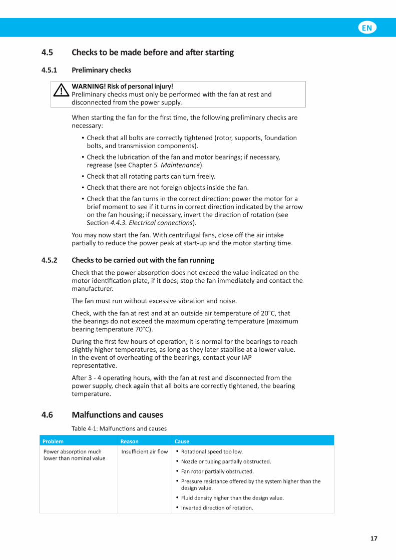
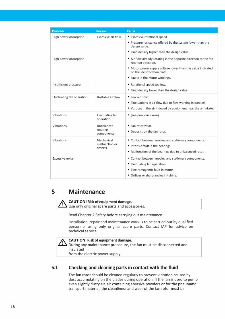
4.6 Malfunctions and causes Table4-1:Malfunctionsandcauses
Problem Reason Cause
Powerabsorptionmuchlowerthannominalvalue
Insufficientairflow • Rotationalspeedtoolow.
• Nozzleortubingpartiallyobstructed.
• Fanrotorpartiallyobstructed.
• Pressureresistanceofferedbythesystemhigherthanthedesignvalue.
• Fluiddensityhigherthanthedesignvalue.
• Inverteddirectionofrotation.
18
Problem Reason Cause
Highpowerabsorption Excessiveairflow • Excessiverotationalspeed.
• Pressureresistanceofferedbythesystemlowerthanthedesignvalue.
• Fluiddensityhigherthanthedesignvalue.
Highpowerabsorption • Airflowalreadyrotatingintheoppositedirectiontothefanrotationdirection.
• Motorpowersupplyvoltagelowerthanthevalueindicatedontheidentificationplate.
• Faultsinthemotorwindings.
Insufficientpressure • Rotationalspeedtoolow.
• Fluiddensitylowerthanthedesignvalue.
Fluctuatingfanoperation Unstableairflow • Lowairflow.
• Fluctuationsinairflowduetofansworkinginparallel.
• Vorticesintheairinducedbyequipmentneartheairintake.
Vibrations Fluctuatingfanoperation
• (seepreviouscause)
Vibrations Unbalancedrotatingcomponents
• Fanrotorwear.
• Depositsonthefanrotor.
Vibrations Mechanicalmalfunctionordefects
• Contactbetweenmovingandstationarycomponents.
• Intrinsicfaultinthebearings.
• Malfunctionofthebearingsduetounbalancedrotor.
Excessivenoise • Contactbetweenmovingandstationarycomponents.
• Fluctuatingfanoperation.
• Electromagneticfaultinmotor.
• Orificesorsharpanglesintubing.
5 MaintenanceCAUTION! Risk of equipment damage. Useonlyoriginalsparepartsandaccessories.
ReadChapter2Safetybeforecarryingoutmaintenance.
Installation,repairandmaintenanceworkistobecarriedoutbyqualifiedpersonnel using only original spare parts. Contact IAP for advice ontechnicalservice.
CAUTION! Risk of equipment damage. Duringanymaintenanceprocedure,thefanmustbedisconnectedandinsulatedfromtheelectricpowersupply.
5.1 Checking and cleaning parts in contact with the fluidThefanrotorshouldbecleanedregularlytopreventvibrationcausedbydustaccumulatingonthebladesduringoperation.Ifthefanisusedtopumpevenslightlydustyair,aircontainingabrasivepowdersorforthepneumatictransportmaterial,thecleanlinessandwearofthefanrotormustbe
19
EN
checkedregularly.Dirtdepositsontherotororwearofpartsoftherotorcancauseundesirablevibrationsduringfanoperation.Ifanypartoftherotorisexcessivelyworn,itisimperativethattherotorbereplaced.Foranyinformationandbeforecarryingoutanymodificationtooneofourfans,pleasecontactIAPandquotethepartnumberfoundonthefanidentificationplate.
NOTE! Anintegratedmaintenanceprogramisnecessaryfornormalandcorrectoperationofthefan,andalsoensuresgreatersafetyfortheoperator.
NOTE! Regularcleaningandmaintenancetogetherwithlubrication,arevitalforensuringcorrectoperationandgreaterdurabilityofthefan.
5.2 Disassembly
WARNING! Risk of personal injury!Allthedisassemblyandreassemblyoperationsdescribedbelowmustonlybecarriedoutbyqualifiedandauthorisedpersonnel.Fornoreasonwhatsoevermusttheoperatororfactorypersonnelcarryouttheseoperations.
CAUTION! Allthedisassemblyandreassemblyworkmustbecarriedoutwiththefollowingconditions:• Youmustbeabsolutelycertainthatthefaniscompletelystationary(fanrotoratrest);disconnecttheelectricalpoweratthemainpanelwiththeswitch,locktheswitchwithapadlockandhandthekeytotheheadofmaintenance.
• Theworkingenvironmentmustbeequippedwitheverytoolnecessaryandmustbefreeofanyhazards.
• Everypiecetoberefittedmustbethoroughlycleaned,degreasedandlubricatedasnecesasarybeforerefitting.
5.2.1 Intake nozzlesUndothenozzlesecuringnutsfromthefanhousing.Slideoutthenozzle.
5.2.2 HousingWithallorientablefans,thehousingissecuredtotheframebybolts.Simplyundothesecuringnutsattheframeplate.Withnon-orientablefanswithsingle-piecehousings,thehousingcannotbedisassembled.Thehousingincertainfantypesmaybedividedintotwoormorepieces,securedtogetherbybolts.
5.2.3 Fan rotorRemovethenozzleand,wherepossible,thefanhousing.Withsingleintakefans:removethescrewtogetherwiththelock-ringanduseasuitablysizedextractor.Werecommendsettingupasupportfortherotorbeforeextractingitcompletely.Inanyevent,thisoperationmustalwaysbecarriedoutwithgreatcare,avoidinganyknocksthatcouldalterthebalanceoftherotorordeformit.
20
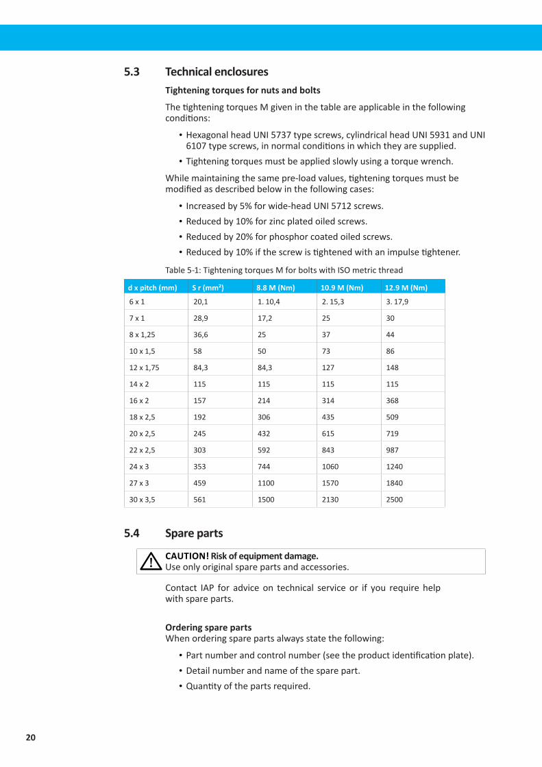
5.3 Technical enclosuresTightening torques for nuts and bolts
ThetighteningtorquesMgiveninthetableareapplicableinthefollowingconditions:
• HexagonalheadUNI5737typescrews,cylindricalheadUNI5931andUNI6107typescrews,innormalconditionsinwhichtheyaresupplied.
• Tighteningtorquesmustbeappliedslowlyusingatorquewrench.
Whilemaintainingthesamepre-loadvalues,tighteningtorquesmustbemodifiedasdescribedbelowinthefollowingcases:
• Increasedby5%forwide-headUNI5712screws.• Reducedby10%forzincplatedoiledscrews.• Reducedby20%forphosphorcoatedoiledscrews.• Reducedby10%ifthescrewistightenedwithanimpulsetightener.
Table5-1:TighteningtorquesMforboltswithISOmetricthread
d x pitch (mm) S r (mm²) 8.8 M (Nm) 10.9 M (Nm) 12.9 M (Nm)
6x1 20,1 1.10,4 2.15,3 3.17,9
7x1 28,9 17,2 25 30
8x1,25 36,6 25 37 44
10x1,5 58 50 73 86
12x1,75 84,3 84,3 127 148
14x2 115 115 115 115
16x2 157 214 314 368
18x2,5 192 306 435 509
20x2,5 245 432 615 719
22x2,5 303 592 843 987
24x3 353 744 1060 1240
27x3 459 1100 1570 1840
30x3,5 561 1500 2130 2500
5.4 Spare parts
CAUTION! Risk of equipment damage. Useonlyoriginalsparepartsandaccessories.
Contact IAP for advice on technical service or if you require helpwithspareparts.
Ordering spare partsWhenorderingsparepartsalwaysstatethefollowing:
• Partnumberandcontrolnumber(seetheproductidentificationplate).• Detailnumberandnameofthesparepart.• Quantityofthepartsrequired.
21
EN
5.5 RecyclingTheproducthasbeendesignedforcomponentmaterialstoberecycled.Itsdifferentmaterialtypesmustbehandledaccordingtorelevantlocalregulations.
Contact Information
Industrial Air Purification, Inc.
2544 Highway 70 East, Cookeville, TN 38506
Tel : (931) 372-0050
E-mail : [email protected]
Website : www.IAP-AirProducts.com


![Instruction Manual · Instruction Manual V GmbHISION H[y ]bris Shock ABSORBER](https://img.pdfslide.us/doc/110x75/5f0c9fda7e708231d436548d/instruction-manual-instruction-manual-v-gmbhision-hy-bris-shock-absorber.jpg)