Embed Size (px)
Citation preview

READ THROUGH THIS MANUAL BEFORE STARTING CONSTRUCTION. IT CONTAINS IMPORTANT INSTRUCTIONS AND WARNINGS CONCERNING THE ASSEMBLY AND USE OF THIS MODEL.
Champaign, Illinois(217) 398-8970
INSTRUCTION MANUAL
Rotor Span: 27.5 in [700mm]Height: 9.3 in [236 mm]Length: 24 in [610mm]Weight: 18.4 oz [521g] no battery,
25 oz [708g] w/fl ight battery (GPMP0520)Motor: 420 Brushless out-runner motorRadio: Futaba® 6EX 6-channel 2.4GHz FASST transmitter Futaba R606FS 6-channel 2.4GHz FASST receiverServos: Futaba S3114 micro HT servoGyro: Heli-Max™ Heading Lock HM 4000 Gyro w/remote dual gain
™
• Never charge in excess of 4.20V per cell.• If the battery should become damaged, discard the
battery. Do not attempt to use a damaged battery.• Do not leave the charger unattended while charging.
Disconnect the battery and remove input power from the charger immediately if either becomes hot! However, it is normal for the charger to get warm.
• Disconnect the battery from the charger and carefully move the battery to a fi reproof location if the battery begins to swell or smoke!
• Never charge at currents greater than 1C.• Always charge in a fi reproof location.• Never trickle charge.• Never allow the battery temperature to exceed 150° F
[65° C].• Never disassemble or modify pack wiring in any way or
puncture cells.• Never discharge below 2.5V per cell.
• Do not allow water, moisture or foreign objects intothe charger.
• Do not block the air intake holes, which could cause the charger to overheat.
• Do not place the charger or any battery on a fl ammable surface or near a combustible material while in use.
• Do not charge on a carpet, cluttered workbench, paper, plastic, vinyl, leather, wood, or inside an R/C model.
• Never charge inside a full sized vehicle.• Always disconnect the battery from the charger and the
power supply from the charger when not in use. • Do not attempt to charge a battery if it is swollen or hot.• ALWAYS KEEP OUT OF REACH OF CHILDREN.
IMPORTANT PRECAUTIONS
WARNING!! Read the entire instruction sheet included with your battery and charger. Failure to follow all instructions could cause permanent damage to the battery, charger or its surroundings, and cause bodily harm!

2
TABLE OF CONTENTS
INTRODUCTION ............................................................... 2AMA .................................................................................. 2SAFETY PRECAUTIONS ................................................. 2ITEMS REQUIRED ............................................................ 3KIT INSPECTION .............................................................. 3WARRANTY ...................................................................... 3KIT CONTENTS ................................................................ 4OPERATIONAL WARNINGS ............................................ 4ELECTRIC MOTOR WARNING ........................................ 5TRANSMITTER FUNCTION SWITCHES ......................... 5CONTROLS ...................................................................... 6GET THE MODEL READY TO FLY ................................... 7TRACKING THE MAIN BLADES ...................................... 9QUICK REFERENCE TO TRANSMITTER FUNCTIONS ... 11LINKAGE ROD LENGTHS ............................................. 12ORDERING PARTS ........................................................ 12EXPLODED VIEWS ........................................................ 14PARTS IMAGES .............................................................. 16OPTIONAL PARTS ......................................................... 18
INTRODUCTION
Thank you for purchasing the Heli-Max AXE™ 400 3D RTF Helicopter. We are certain you will get many hours of enjoyment out of this model. If you should have any questions or concerns please feel free to contact us at:
For the latest technical updates or manual corrections to the AXE 400 3D RTF visit the Heli-Max web site at www.helimax-rc.com. Open the “Helicopters” link, and then select the AXE 400 3D RTF. If there is new technical information or changes to this model a “tech notice” box will appear in the upper left corner of the page.
AMA
We urge you to join the AMA (Academy of Model Aeronautics) and a local R/C club. The AMA is the governing body of model aviation and membership is required to fl y at AMA clubs. Though joining the AMA provides many benefi ts, one of the primary reasons to join is liability protection. Coverage is not limited to fl ying at contests or on the club fi eld. It even applies to fl ying at public demonstrations and air shows. Failure to comply with the Safety Code (excerpts printed in the back of the manual) may endanger insurance coverage. Additionally, training programs and instructors are available at AMA club sites to help you get started the right way. There are over
2,500 AMA chartered clubs across the country. Contact the AMA at the address or toll-free phone number below.
Academy of Model Aeronautics5151 East Memorial Drive
Muncie, IN 47302Tele: (800) 435-9262Fax (765) 741-0057
Or via the Internet at:www.modelaircraft.org
IMPORTANT!!! Two of the most important things you can do to preserve the radio controlled aircraft hobby are to avoid fl ying near full-scale aircraft and avoid fl ying near or over groups of people.
SAFETY PRECAUTIONS
Failure to follow these safety precautions may result in severe injury to yourself and others.
• Keep your face and body as well as all spectators away from the plane of rotation of the rotors whenever the battery is connected.
• Keep these items away from the rotors: loose clothing, shirt sleeves, ties, scarfs, long hair or loose objects such as pencils or screwdrivers that may fall out of shirt or jacket pockets into the rotors.
• The spinning blades of a model helicopter can cause serious injury. When choosing a fl ying site for your AXE 400 3D RTF, stay clear of buildings, trees and power lines. AVOID fl ying in or near crowded areas. DO NOT fl y close to people, children or pets. Maintain a safe pilot-to-helicopter distance while fl ying.
1. Your AXE 400 3D RTF should not be considered a toy, but rather a sophisticated, working model that functions very much like a full-size helicopter. Because of its performance capabilities, the AXE 400 3D RTF, if not assembled and operated correctly, could possibly cause injury to yourself or spectators and damage to property.
2. You must assemble the model according to the instructions. Do not alter or modify the model, as doing so may result in an unsafe or unfl yable model. In a few cases the instructions may differ slightly from the photos. In those instances the written instructions should be considered as correct.
3. You must correctly install all R/C and other components so that the model operates correctly on the ground and in the air.

4. You must check the operation of the model before every fl ight to insure that all equipment is operating and that the model has remained structurally sound. Be sure to check linkages or other connectors often and replace them if they show any signs of wear or fatigue.
5. If you are not an experienced pilot or have not fl own this type of model before, we recommend that you get the assistance of an experienced pilot in your R/C club for your fi rst fl ights. If you’re not a member of a club, your local hobby shop has information about clubs in your area whose membership includes experienced pilots.
We, as the manufacturer, provide you with a top quality, thoroughly tested helicopter and instructions, but ultimately the quality and fl yability of your fi nished model depends on how you build it; therefore, we cannot in any way guarantee the performance of your completed model, and no representations are expressed or implied as to the performance or safety of your completed model.
Remember: Take your time and follow the instructions to build a safe and enjoyable model.
ITEMS REQUIRED
The following items must be purchased separately:
• (8) AA Alkaline cells (SANP3500 AA 4-pack x2)
FLIGHT BATTERY
Hovering, Basic Aerobatics and 3D• GPMP0406 11.1V 2000mAh Battery LiPo Flight Battery• GPMP0617 Great Planes ElectriFly LiPo 11.1V 2100mAh 20C Power
Hovering, Basic Aerobatics, Mild 3D and Aggressive 3D• GPMP0520 Great Planes LiPo 11.1V 2200mAh 25C T-Rex MX450 Heli• FPWP0327 FlightPower LiPo 11.1V 2170mAh 25C EVO25 3S Balance
Also required is an appropriate battery charger for yourfl ight battery.
KIT INSPECTION
Before starting assembly, take an inventory of the AXE 400 3D RTF to make sure it is complete, and inspect the parts to make sure they are of acceptable quality. If any parts are missing or are not of acceptable quality, or if you need assistance with assembly, contact Product Support. When reporting defective or missing parts, use the part names exactly as they are written in the Kit Contents list.
Heli-Max Product Support:3002 N. Apollo Drive, Suite 1
Champaign, IL 61822Telephone: (217) 398-8970, ext. 5
Fax: (217) 398-7721E-mail: [email protected]
WARRANTY
Heli-Max™ guarantees this kit to be free from defects in both material and workmanship at the date of purchase. This warranty does not cover any component parts damaged by use or modifi cation. In no case shall Heli-Max’s liability exceed the original cost of the purchased kit. Further, Heli-Max reserves the right to change or modify this warranty without notice.
In that Heli-Max has no control over the fi nal assembly or material used for fi nal assembly, no liability shall be assumed nor accepted for any damage resulting from the use by the user of the fi nal user-assembled product. By the act of using the user-assembled product, the user accepts all resulting liability.
If the buyer is not prepared to accept the liability associated with the use of this product, the buyer is advised to return this kit immediately in new and unused condition to the place of purchase.
To make a warranty claim, send the defective part or item to Hobby Services at this address.
Hobby Services3002 N. Apollo Dr., Suite 1
Champaign, IL 61822USA
Include a letter stating your name, return shipping address, as much contact information as possible (daytime telephone number, fax number, e-mail address), a detailed description of the problem and a photocopy of the purchase receipt. Upon receipt of the package the problem will be evaluated as quickly as possible.
3
4
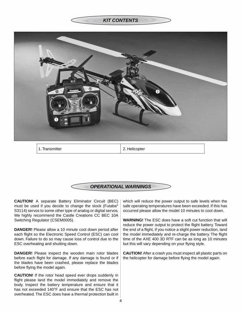
KIT CONTENTS
OPERATIONAL WARNINGS
1. Transmitter 2. Helicopter
1
2
CAUTION! A separate Battery Eliminator Circuit (BEC) must be used if you decide to change the stock (Futaba® S3114) servos to some other type of analog or digital servos. We highly recommend the Castle Creations CC BEC 10A Switching Regulator (CSEM0005).
DANGER! Please allow a 10 minute cool down period after each fl ight so the Electronic Speed Control (ESC) can cool down. Failure to do so may cause loss of control due to the ESC overheating and shutting down.
DANGER! Please inspect the wooden main rotor blades before each fl ight for damage. If any damage is found or if the blades have been crashed, please replace the blades before fl ying the model again.
CAUTION! If the rotor head speed ever drops suddenly in fl ight please land the model immediately and remove the body. Inspect the battery temperature and ensure that it has not exceeded 140°F and ensure that the ESC has not overheated. The ESC does have a thermal protection built in
which will reduce the power output to safe levels when the safe operating temperatures have been exceeded. If this has occurred please allow the model 10 minutes to cool down.
WARNING! The ESC does have a soft cut function that will reduce the power output to protect the fl ight battery. Toward the end of a fl ight, if you notice a slight power reduction, land the model immediately and re-charge the battery. The fl ight time of the AXE 400 3D RTF can be as long as 10 minutes but this will vary depending on your fl ying style.
CAUTION! After a crash you must inspect all plastic parts on the helicopter for damage before fl ying the model again.
5
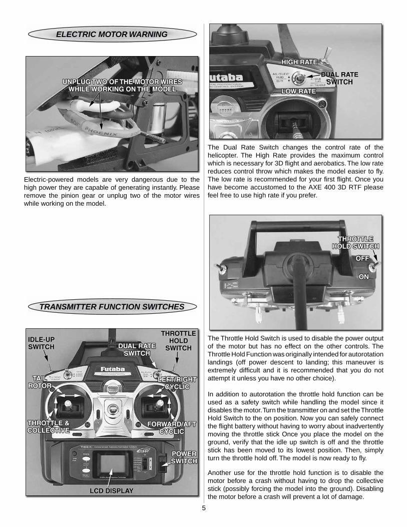
ELECTRIC MOTOR WARNING
Electric-powered models are very dangerous due to the high power they are capable of generating instantly. Please remove the pinion gear or unplug two of the motor wires while working on the model.
TRANSMITTER FUNCTION SWITCHES
The Dual Rate Switch changes the control rate of the helicopter. The High Rate provides the maximum control which is necessary for 3D fl ight and aerobatics. The low rate reduces control throw which makes the model easier to fl y. The low rate is recommended for your fi rst fl ight. Once you have become accustomed to the AXE 400 3D RTF please feel free to use high rate if you prefer.
The Throttle Hold Switch is used to disable the power output of the motor but has no effect on the other controls. The Throttle Hold Function was originally intended for autorotation landings (off power descent to landing; this maneuver is extremely diffi cult and it is recommended that you do not attempt it unless you have no other choice).
In addition to autorotation the throttle hold function can be used as a safety switch while handling the model since it disables the motor. Turn the transmitter on and set the Throttle Hold Switch to the on position. Now you can safely connect the fl ight battery without having to worry about inadvertently moving the throttle stick Once you place the model on the ground, verify that the idle up switch is off and the throttle stick has been moved to its lowest position. Then, simply turn the throttle hold off. The model is now ready to fl y.
Another use for the throttle hold function is to disable the motor before a crash without having to drop the collective stick (possibly forcing the model into the ground). Disabling the motor before a crash will prevent a lot of damage.

666
The Idle-Up function is disabled within the transmitter for safety. If you are beginning aerobatics or are an experienced pilot and feel you have a need for the Idle Up function, then please follow the instructions on page 11 to enable this function.
CONTROLS
RIGHT CYCLIC
Moving the cyclic stick right will cause the helicopter to tilt right and start moving that direction.
LEFT CYCLIC
Moving the cyclic stick left will cause the helicopter to tilt left and start moving in that direction.
AFT CYCLIC
Moving the cyclic stick backwards (towards you) will cause the helicopter to tilt backwards and start moving that direction.
FORWARD CYCLIC
Moving the cyclic stick forward (away from you) will cause the helicopter to tilt forward and start moving that direction.
7
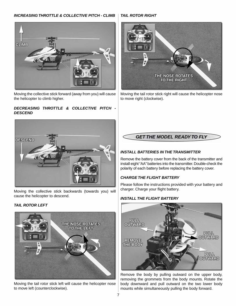
INCREASING THROTTLE & COLLECTIVE PITCH - CLIMB
Moving the collective stick forward (away from you) will cause the helicopter to climb higher.
DECREASING THROTTLE & COLLECTIVE PITCH - DESCEND
Moving the collective stick backwards (towards you) will cause the helicopter to descend.
TAIL ROTOR LEFT
Moving the tail rotor stick left will cause the helicopter nose to move left (counterclockwise).
TAIL ROTOR RIGHT
Moving the tail rotor stick right will cause the helicopter nose to move right (clockwise).
GET THE MODEL READY TO FLY
INSTALL BATTERIES IN THE TRANSMITTER
Remove the battery cover from the back of the transmitter and install eight “AA” batteries into the transmitter. Double-check the polarity of each battery before replacing the battery cover.
CHARGE THE FLIGHT BATTERY
Please follow the instructions provided with your battery and charger. Charge your fl ight battery.
INSTALL THE FLIGHT BATTERY
Remove the body by pulling outward on the upper body, removing the grommets from the body mounts. Rotate the body downward and pull outward on the two lower body mounts while simultaneously pulling the body forward.
8
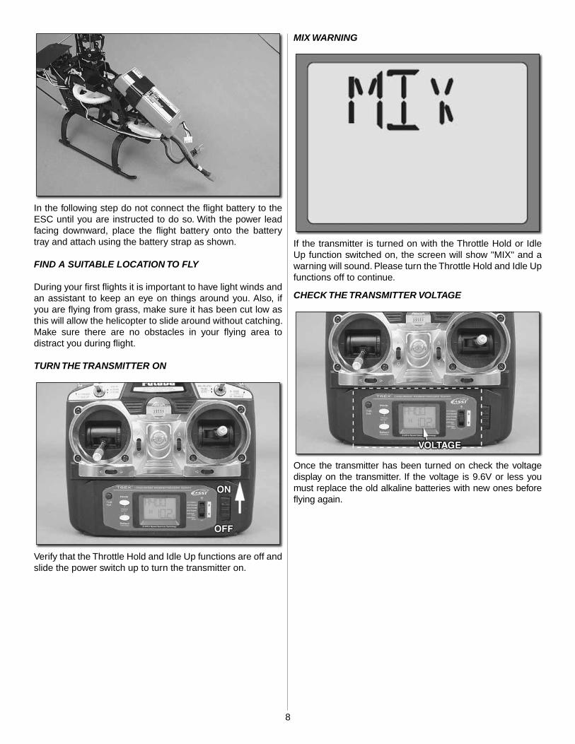
In the following step do not connect the fl ight battery to the ESC until you are instructed to do so. With the power lead facing downward, place the fl ight battery onto the battery tray and attach using the battery strap as shown.
FIND A SUITABLE LOCATION TO FLY
During your fi rst fl ights it is important to have light winds and an assistant to keep an eye on things around you. Also, if you are fl ying from grass, make sure it has been cut low as this will allow the helicopter to slide around without catching. Make sure there are no obstacles in your fl ying area to distract you during fl ight.
TURN THE TRANSMITTER ON
Verify that the Throttle Hold and Idle Up functions are off and slide the power switch up to turn the transmitter on.
MIX WARNING
If the transmitter is turned on with the Throttle Hold or Idle Up function switched on, the screen will show "MIX" and a warning will sound. Please turn the Throttle Hold and Idle Up functions off to continue.
CHECK THE TRANSMITTER VOLTAGE
Once the transmitter has been turned on check the voltage display on the transmitter. If the voltage is 9.6V or less you must replace the old alkaline batteries with new ones before fl ying again.
9
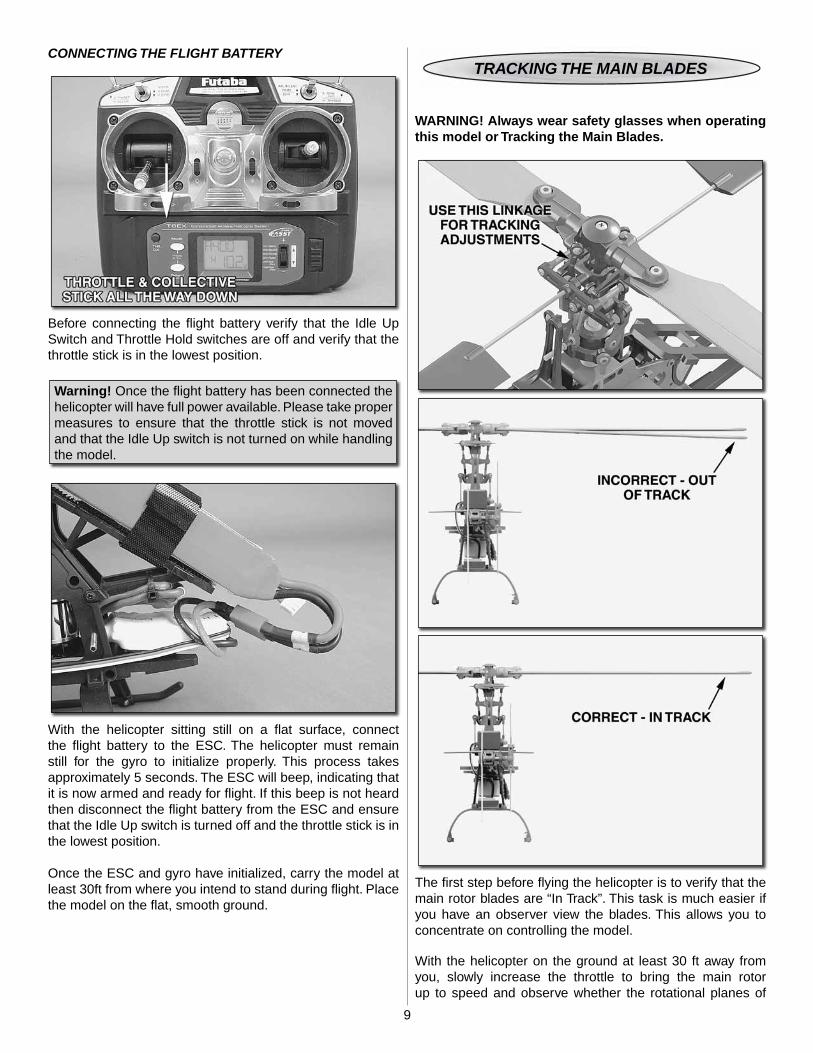
CONNECTING THE FLIGHT BATTERY
Before connecting the fl ight battery verify that the Idle Up Switch and Throttle Hold switches are off and verify that the throttle stick is in the lowest position.
Warning! Once the fl ight battery has been connected the helicopter will have full power available. Please take proper measures to ensure that the throttle stick is not moved and that the Idle Up switch is not turned on while handlingthe model.
With the helicopter sitting still on a fl at surface, connect the fl ight battery to the ESC. The helicopter must remain still for the gyro to initialize properly. This process takes approximately 5 seconds. The ESC will beep, indicating that it is now armed and ready for fl ight. If this beep is not heard then disconnect the fl ight battery from the ESC and ensure that the Idle Up switch is turned off and the throttle stick is in the lowest position.
Once the ESC and gyro have initialized, carry the model at least 30ft from where you intend to stand during fl ight. Place the model on the fl at, smooth ground.
TRACKING THE MAIN BLADES
WARNING! Always wear safety glasses when operating this model or Tracking the Main Blades.
The fi rst step before fl ying the helicopter is to verify that the main rotor blades are “In Track”. This task is much easier if you have an observer view the blades. This allows you to concentrate on controlling the model.
With the helicopter on the ground at least 30 ft away from you, slowly increase the throttle to bring the main rotor up to speed and observe whether the rotational planes of
10
the blades are the same. If they are not, adjust one of the linkages to bring the blades into the same plane.
TAKEOFF
During your fi rst fl ight it is important to have light winds and an assistant to keep an eye on things around you. Also, if you are fl ying from grass, make sure it’s cut low as this will allow the helicopter to slide around without catching. Also make sure there are no obstacles in your fl ying area to distract you.
Slowly add power and observe the model. If you feel it needs trimming, do so before lift off. You will fi nd that model helicopters never allow you to return the sticks to center. Simply hold the sticks as needed to keep a steady hover. Please don’t fi ght the trim too much as it is a normal thing to experience. Winds have a large effect on model helicopters. Please wait for calmer days and slowly work into windy days.
You will notice the cyclic controls lag slightly behind your inputs. This is perfectly normal and something you become accustomed to. It is normal to drift around some in a hover, until you get used to fl ying the model. The cyclic controls on the AXE 400 3D RTF are fairly sensitive so only small movements are necessary.
HOVERING
Once the helicopter is in the air simply try to keep the helicopter in one spot. This will take some practice and wind has a big effect on the stability of the helicopter. Be patient and slowly progress. Trying to rush the learning process can be costly.
LANDING
Level the helicopter into a steady hover and slowly decrease power until the helicopter settles onto the ground.
BASIC MANEUVERS
Once you are comfortable with hovering at different orientations and landing, it’s time to move on to more advanced maneuvers.
Slow Pirouettes: Add a small amount of tail rotor (left or right) and try rotating the helicopter slightly sideways and see if you can hold it there. If you become uncomfortable bring the tail back towards you. Once you are comfortable, try moving the helicopter to the side and turning back.
Then fl y back to the other side in straight lines. You can try rotating the helicopter around 360°, which is called a pirouette. The helicopter can drift during this maneuver so make certain you have plenty of room when you fi rst start practicing.
Nose-In Hovering: After pirouettes it’s time to move onto nose-in hovering. The best bet is to wait for a calm day. Take off and climb to 15 feet, practice half pirouettes from tail-in
to nose-in hovering, and try to lengthen the delay between transitions. This will allow you to practice nose-in and still give you a chance to get out of trouble. As you improve you’ll remain nose-in for longer periods of time.
Forward Flight: Now it’s time to work into basic forward fl ight. Just take the basic hovering maneuvers listed above and slowly fl y out farther and faster and always bring the helicopter back after one pass. Practice controlled slow fl ight in close as well. The more time you spend practicing here, the easier things will be later on.
AEROBATICS
So you are getting comfortable in fast forward fl ight? Well, now it’s time to slowly progress into aerobatics. Once you are in forward fl ight start using the idle up switch* which raises the rotor RPM for aerobatics and allows the AXE 400 3D RTF to fl y inverted (*please refer to page 11 to activate this function). Also, in wind it may be diffi cult to descend to land without the idle up on.
Chandelles: Your fi rst step is chandelles. Fly straight across in front of you and pull up to a 45° angle. Now at the top, when the helicopter slows down to a stop, apply left or right tail rotor to bring the nose around 180° and continue back down the 45° angle. As you progress with the maneuver you can pull a greater angle than 45°, but 90° would be considered a stall turn.
Loops: Once you become comfortable with the chandelles and stall turns it’s time to move onto the loop. The key to the loop is to enter with plenty of speed. Start pulling aft cyclic to enter the loop and as the model transitions to inverted at the top of the loop pull back on the throttle (towards negative (–) collective). This will help maintain altitude. As the model returns back to vertical add some positive (+) collective to maintain the speed. One of the most common mistakes made on loops is using too much negative (–) collective at the top.
Flips: Be certain to start with plenty of altitude. From an upright hover slowly add in full forward cyclic. As the model approaches vertical, bring the collective stick back to center. Now, as the model continues to inverted, you will need to start adding in negative (–) collective (or pull the collective stick back towards yourself). As the model transitions back to vertical, again bring the collective stick back to the middle and start adding in positive (+) collective as the model returns back to upright. It’s simply a matter of timing. The most important thing is, do not throw the sticks around. This can cause the head speed to drop and may cause the tail to drift.
Inverted Hovering: Keep in mind fl ying a helicopter inverted is very diffi cult but can be learned. One of the main problems is 3 out of 4 of the controls are reversed (forward/aft cyclic, collective and tail rotor). You have to mentally reverse these while fl ying. It will take some practice. Take the loop you learned above and just hold the inverted portion for short

11
periods of time. As you become accustomed to the reversed controls, you will extend the time inverted. It is very diffi cult and will take some practice. Also, make sure you have plenty of altitude for recovery if needed.
ACTIVATING THE IDLE UP FUNCTION
WARNING! If you inadvertently select the Idle-Up function the throttle will instantly power up to at least 85% power and this may damage the helicopter or possibly cause injury to yourself or others. For safety leave this function disabled until you require it. Switch to the Idle Up function once you are up and hovering in the normal fl ight condition and be sure to switch back to the Normal fl ight condition before landing.
Please keep in mind that the pitch curve used for “Normal” fl ight mode is -1 degree to +10 degrees. Once the Idle Up function is enabled the Idle Up Pitch Curve will be -10 degrees to +10 degrees. The additional 9° of negative pitch will cause the helicopter to be extremely sensitive to negative pitch inputs. Care must be taken in order to avoid slamming the model into the ground when fl ying in Idle Up mode.
If you are beginning aerobatics or are an experienced pilot and feel you have a need for the Idle Up function, then please follow the instructions within the transmitter manual (Page 24) and enable the “I-TH” function. The Idle Up throttle and pitch curves are already set up for you so only the function needs to be enabled.
GOOD LUCK AND GREAT FLYING!
QUICK REFERENCE TOTRANSMITTER FUNCTIONS
Please refer to the included manufacturer’s instruction manual for complete details for each function. The initial set up of the transmitter suits a beginner modeler. If you feel something needs to be changed, please use the items listed below as a general guide.
[D/R] – Dual Rate. Adjustment range from 30% to 100%. You may adjust these to suit your preferences. Default Settings – 100% for High Rate and 70% for Low Rate. Lower percentage equals less control throw.
[D/R - EXPO] – Exponential Rate. Adjustment range from 30% to 100%. You may adjust these to suit you. Lower percentages will create a softer feeling around center stick. Default Settings -50% for High Rate and -35% for Low Rate.
[GYRO] – Adjusts the amount of corrective gain the gyro uses to make corrections. Higher percentages may hold the tail better. If you notice the tail drifting in fl ight, then raise the gain percentage. If you notice the tail oscillating quickly reduce the gain. A gain of 45% was found to be the best starting point.
[SWSH] – Adjust the cyclic and collective control rate. Please use the dual rate function to adjust the left/right cyclic and forward/aft cyclic rate. If you feel the model could use some additional collective pitch please feel free to raise the [P] function up to 10%. The starting value is +35% and the maximum value that should be used is +45%.

12
LINKAGE ROD LENGTHS
Linkage A
Linkage B
Linkage C
Linkage D
Linkage E
Linkage F
Tail Rotor Pushrod 286mm
23mm
20mm
42mm
31.5mm
43mm
43mm
ORDERING PARTS
Replacement parts for the Heli-Max AXE 400 3D RTF are available using the order numbers in the Parts List on page 18. The fastest, most economical service can be provided by your hobby dealer.
To locate a hobby dealer, visit the Hobbico web site atwww.hobbico.com. Choose “Where to Buy” at the bottom of the menu on the left side of the page. Follow the instructions provided on the page to locate a U.S., Canadian or International dealer.
Parts may also be ordered directly from Hobby Services by calling (217) 398-0007, or via facsimile at (217) 398-7721, but full retail prices and shipping and handling charges will apply. Illinois and Nevada residents will also be charged sales tax. If ordering via fax, include a Visa® or MasterCard®
number and expiration date for payment.
Mail parts orders and payments by personal check to:
Hobby Services3002 N. Apollo Drive, Suite 1
Champaign, IL 61822
Be certain to specify the order number exactly as listed in the Parts List. Payment by credit card or personal check only; no C.O.D.
If additional assistance is required for any reason contact Product Support by e-mail at [email protected], or by telephone at (217) 398-8970.
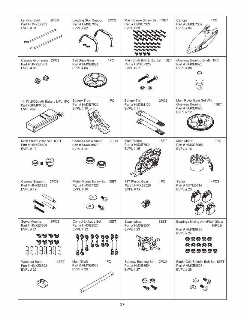
AXE 400 3D PARTS LIST
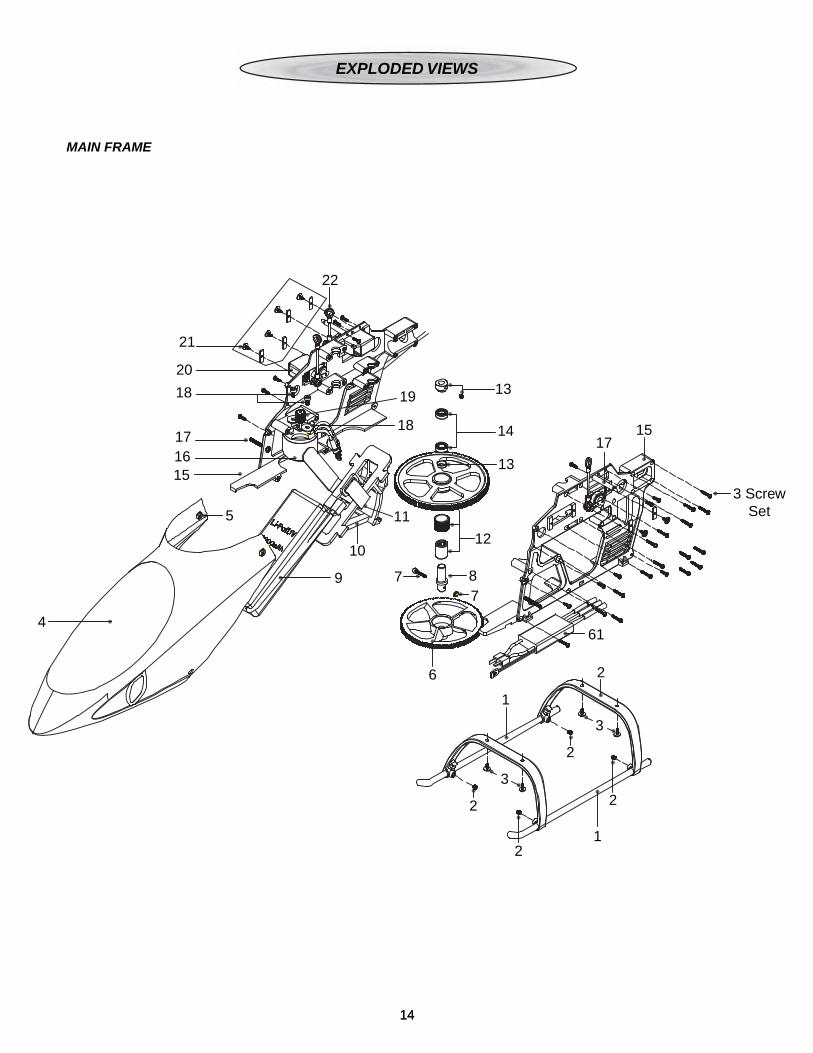
# Stock # .......... Description .......................... Includes1 HMXE7931 .... Landing Skid ......................................22 HMXE7932 .... Landing Skid Support ........................23 HMXE7324 .... Main Frame Screw Set ....................444 HMXE7382 .... Canopy Red ......................................15 HMXE7383 .... Canopy Grommets.............................26 HMXE8024 .... Tail Gear Drive ...................................17 HMXE7325 .... Main Shaft Bolt & Nut Set ..................28 HMXE8025 .... One-Way Bearing Shaft .....................19 GPMP0406 .... 11.1V 2000mAh LiPo Battery ............110 HMXE7933 .... Battery Tray ........................................111 HMXE4130 .... Battery Tie .........................................212 HMXE8026 ......Main Rotor Gear w/One-Way Bearing ...113 HMXE8520 .... Main Shaft Collar ...............................114 HMXE8825 .... Bearings Main Shaft ..........................215 HMXE7934 .... Main Frame ........................................116 HMXG8005 .... Main Motor 3500 KV ..........................117 HMXE7935 .... Canopy Supports ...............................218 HMXE7326 .... Motor Mount Screws ..........................219 HMXE8028 .... 13T Pinion Gear ................................120 FUTM0414 .... Servos ...............................................421 HMXE7936 .... Servo Mounts ....................................822 HMXE8521 .... Control Linkage Set ...........................1

13
23 HMXE8501 .... Swashplate ........................................124 HMXE8512 .... Mixing Arms .....................................1625 HMXE8502 .... Washout Base ...................................126 HMXE8503 .... Main Shaft .........................................127 HMXE8504 .... Seesaw Bushing Set .........................228 HMXE8505 .... Spindle Bolt Set .................................129 HMXE8506 .... Blade Grip Bolt Set ............................130 HMXE8507 .... Main Blade Grips ...............................131 HMXE8508 .... Dampening Shims .............................132 HMXE8827 .... Bearings Main Grips ..........................633 HMXE8509 .... Head Dampeners ..............................434 HMXE8510 .... Feathering Spindle ............................135 HMXE8511 .... Head Block ........................................136 HMXE8512 .... Mixing Arms .......................................237 HMXE8513 .... Seesaw ..............................................138 HMXE8514 .... Flybar Control Set ..............................139 HMXE8515 .... Flybar .................................................140 HMXE8516 .... Flybar Paddles ...................................241 HMXE8517 .... Control Ball Set ................................2642 HMXE8519 .... Washout Control Arms ......................243 HMXE8518 .... Swashplate Stay ................................144 HMXE8027 .... Tail Belt Drive Gear ............................145 HMXE8336 .... Tail Boom Support .............................246 HMXE8637 .... Tail Rotor Linkage ..............................147 HMXE8638 .... Tail Servo Mounts ..............................248 HMXE8639 .... Tail Boom ...........................................149 HMXE8640 .... Horizontal Fin Mount .........................150 HMXE8641 .... Horizontal Fin ....................................151 HMXE8642 .... Vertical Fin .........................................152 HMXE8643 .... Tail Rotor Gear Case .........................153 HMXE8644 .... Tail Belt Pulley ...................................154 HMXE8645 .... Tail Rotor Shaft Assembly..................155 HMXE8646 .... Tail Rotor Control Arm .......................156 HMXE8647 .... Tail Pitch Slider Control Set ...............157 HMXE8648 .... Tail Rotor Hub ....................................158 HMXE8649 .... Tail Rotor Grips ..................................159 HMXE8426 .... Tail Rotor Blades ...............................260 HMXE8323 .... Main Rotor Blades .............................261 HMXM2009 ... Brushless ESC ..................................162 HMXE8650 .... Tail Rotor Drive Belt ...........................1 HMXE7384 .... Canopy Green RXR ...........................1 HMXE7385 .... Canopy White ...................................1 HMXE8029 .... Main Rotor Gear without One-Way Bearing ...............................................1
OPTIONAL PARTS
Stock # ................. DescriptionHMXE7493 .... CNC Mixer Arms (2) AXE 400HMXE7483 .... CNC Head Block AXE 400HMXE7482 .... CNC Main Blade Grips (2) AXE 400HMXE7487 .... CNC Seesaw AXE 400HMXE7484 .... CNC Flybar Carrier AXE 400HMXE7485 .... CNC Washout Arms (2) AXE 400HMXE7486 .... CNC Washout Base AXE 400HMXE7488 .... CNC Swashplate AXE 400HMXE7489 .... CNC Tail Case AXE 400HMXE7490 .... CNC Tail Drive Belt Pulley AXE 400HMXE7491 .... CNC Counter Drive Belt Pulley AXE 400HMXE7492 .... CNC Tail Blade Grips (2) AXE 400HMXE7494 .... CNC Tail Servo Mount (2) AXE 400HMXE7495 .... CNC Boom Support Ends (4) AXE 400HMXE7496 .... CNC Boom and Fin Clamp AXE 400HMXE7497 .... CNC Head Button AXE 400HMXE7498 .... Carbon Fiber Vertical Fin AXE 400HMXE7499 .... Carbon Fiber Horizontal Fin AXE 400
1414
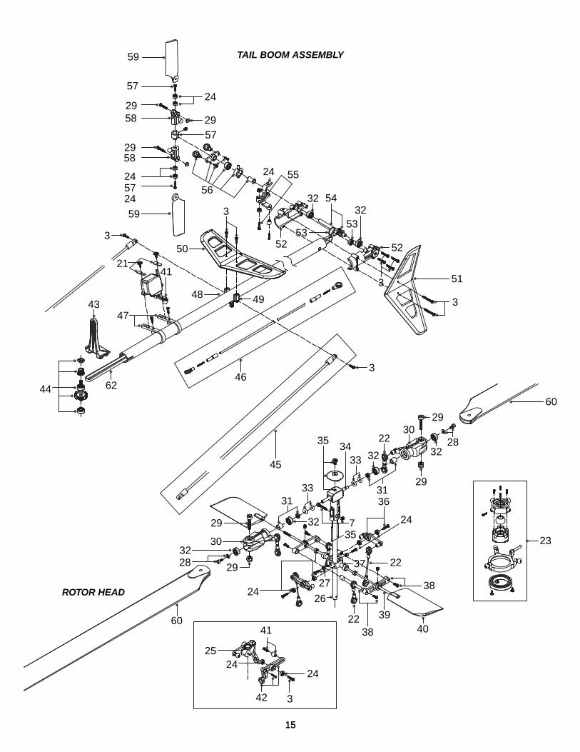
EXPLODED VIEWS
9 7
6
1
2
2
2
3
3
2
21
78
12
11
10
5
15
4
1617
18
20
21
22
19
18
13
13
1417
15
61
3 ScrewSet
MAIN FRAME
44 62
4347
21
3
41
48
50
56
3
24 55
32 5432
5353
3
52
51
3
3
52
49
46
45
59
5724
24
58
57
57
59
24
29
5829
29
24
29
29
60
60
2832
30
27
26
32
3133
333435 22
32
30
735
3631
29
29
3228
37 22
22
24
38
38
394041
2524
24
23
342
TAIL BOOM ASSEMBLY
ROTOR HEAD
1515

1616
Blade Grip Bolt Set 1SetPart #HMXE8506EVPL #29
Head Dampeners 4PcsPart #HMXE8509EVPL #33
Seesaw 1PcPart #HMXE8513EVPL #37
Control Ball Set 1SetPart #HMXE8517EVPL #41
Tail Boom Support 1SetPart #HMXE8336EVPL #45
Horizontal Fin Brace 1PcPart #HMXE8640EVPL #49
Tail Belt Pulley 1SetPart #HMXE8644EVPL #53
Tail Rotor Shaft Assembly 1SetPart #HMXE8645EVPL #54
Horizontal Fin 1PcPart #HMXE8641EVPL #50
Tail Rotor Pushrod 1SetPart #HMXE8637EVPL #46
Washout Control Arm Set 1SetPart #HMXE8519EVPL #42
Flybar Control Set 1SetPart #HMXE8514EVPL #38
Feathering Spindle 1PcPart #HMXE8510EVPL #34
Dampening Shim Set 1SetPart #HMXE8508EVPL #31
Bearings Main Grips/Tail ShaftPart #HMXE8827 6PcsEVPL #31
Mixing Arms 2PcsPart #HMXE8512EVPL #36
Flybar Paddles 2PcsPart #HMXE8516EVPL #40
Tail Rotor Belt Drive Gear 1SetPart #HMXE8027EVPL #44
Tail Boom 1PcPart #HMXE8639EVPL #48
Tail Rotor Gear Case 1SetPart #HMXE8643EVPL #52
Tail Pitch Slider Control Set 1SetPart #HMXE8647EVPL #56
Head Block 1SetPart #HMXE8511EVPL #35
Flybar 1PcPart #HMXE8515EVPL #39
Swashplate Stay 1PcPart #HMXE8518EVPL #43
Tail Servo Mount 2PcsPart #HMXE8638EVPL #47
Vertical Fin 1PcPart #HMXE8642EVPL #51
Tail Rotor Control Arm Set 1SetPart #HMXE8646EVPL #55
Main Blade Grip Set 1SetPart #HMXE8507EVPL #30
17

18
Tail Rotor Hub 1SetPart #HMXE8648EVPL #57
ESC 1PcPart #HMXM2009EVPL #61
Tail Rotor Drive Belt 1PcPart #HMXM2009EVPL #61
Tail Rotor Grips 1PcPart #HMXE8649EVPL #58
Tail Rotor Blades 1PcPart #HMXE8426EVPL #59
Main Rotor Gear 1PcWithout One-Way BearingPart #HMXM8029EVPL #12
Main Rotor Blades 2PcsPart #HMXM8323EVPL #60
OPTIONAL PARTS
CNC Main Blade Grips (2 Pcs)Part # HMXE7482
CNC Head Block (1 Pc)Part # HMXE7483
CNC Flybar Carrier (1 Pc)Part # HMXE7484
CNC Washout Arms (2 Pcs)Part # HMXE7485
CNC Washout Base (1 Pc)Part # HMXE7486
CNC Seesaw (1 Pc)Part # HMXE7487

19
CNC Swashplate (1 Pc)Part # HMXE7488
CNC Tail Case (1 Pc)Part # HMXE7489
CNC Tail Drive Belt Pulley (1 Pc)Part # HMXE7490
CNC Counter Drive Belt Pulley (1 Pc)Part # HMXE7491
CNC Tail Blade Grips (2 Pcs)Part # HMXE7492
CNC Mixer Arms (2 Pcs)Part # HMXE7493
Carbon Fiber Vertical Fin (1 Pc)Part # HMXE7498
Carbon Fiber Horizontal Fin (1 Pc)Part # HMXE7499
CNC Tail Servo Mount (2 Pcs)Part # HMXE7494
CNC Boom Support Ends (2 Pcs)Part # HMXE7495
CNC Boom and Fin Clamp (1 Pc)Part # HMXE7496

Entire Contents © Copyright 2009 HMXE0800 Manual 1.1