Embed Size (px)
Citation preview

INSTRUCTION MANUAL
Model 7SLHigh/Low Limitrol
1262-IN-023-0-02January 1998

2
Field 1 through 4. BASE07SL - Limitrol (High/Low Limit. Shipped as
high limit)
Field 5. INPUT9 - TC Types J, K, T, E, N, S, R, B, L, U, G, D
and Platinel II; and Pt 100 RTD;0 to 20 mAdc and 4 to 20 mAdc0 to 60 mVdc and 12 to 60 mVdc0 to 5 Vdc or 1 to 5 Vdc0 to 10 Vdc or 2 to 10 Vdc
Note: All inputs are factory calibrated andselectable by jumper. Factory set at Type J.
Field 6. OUTPUT (High/Low Limit)1 - Relay (Form C)
Field 7, 8. ALARMS, OPTIONS00 -None10 -One alarm - Relay Form A11 -One alarm - Relay Form A, plus RS-485 and
one logic input.Note: When code 11 is specified, instrumentlength is 4.8 inches (122 mm)
Field 9. POWER SUPPLY3 - 100 to 240 Vac5 - 24 Vac/Vdc
Field 10. Mounting0 - Panel MountR - Wall or Rail Mount
Fields 11 through 15. RESERVED
Model 0 7 S L - 9 1 - 0 0 - 0 - 0 0Field No. 1 2 3 4 5 6 7 8 9 10 1112 13 14 15
1/16 DIN FOUR DIGIT HIGH/LOW LIMITROL

3
Congratulations
. . . on your purchase of one of the easiestto configure controllers on the market.After a three step configuration procedure,your process will be up and running.
If for any reason you encounter difficultywith the controller set-up, please call yoursupplier.
Guide to Simple Set-up
To set-up the controller, only four steps arerequired:1. Wire the instrument.2. Configure the instrument.3. Check the operating mode parameters.
W irin g
OperatingParam eters
Configuration
U npack th eIn strum en t
SV

4
ContentsMounting Requirements ...................................... 5
Panel Mount Controller --------------------- 5Mounting Requirements ...................................... 6
Wall or Rail Mount Controller -------------- 6Dimensions and Rear Terminal Blocks ................ 7
Panel Mount Controllers ------------------- 7Dimensions ......................................................... 9
Wall or Rail Mount Controller -------------- 9Wiring Guidelines .............................................. 10
Panel Mount Controllers ------------------ 10Wiring Guidelines .............................................. 14
Wall or Rail Mount Controller ------------- 14Preliminary Hardware Settings .......................... 20Configuration Procedure ................................... 21Operating Mode ................................................ 27Error Messages ................................................. 32General Specifications ...................................... 33Calibration ......................................................... 37
Calibration Parameters -------------------- 38Procedure ---------------------------------- 38
Maintenance...................................................... 44APPENDIX A ..................................................... 45
Default parameters ------------------------ 45APPENDIX B ..................................................... 47
Thermocouple Compensating CableColor Codes. ------------------------------- 47
CAUTION!
USE WIRE SUITABLEFOR 75° MINIMUM
NOTES:• For supply connections use 16 AWG or
larger wires rated for at least 75° C
• Use copper conductors only
• Class 2 wiring must be separated aminimum of 1/4 inch from any class 1conductor
IMPORTANT!
Terminal identification of the panel mountcontroller is different from terminal identifica-tion of the wall/rail mount controller! Thismanual contains wiring instructions for bothtypes of controllers.
Be sure to follow the instructions that pertainto the controller you are using.

5
Mounting RequirementsPanel Mount Controller
Select a mounting location with the followingcharacteristics:1) Minimal vibration.2) An ambient temperature range between 0 and
50°C (32 and 122 °F).3) Easy access to the rear of the instrument.4) No corrosive gases (sulfuric gas, ammonia,
etc.).5) No water or other fluid (i.e. condensation).6) Relative humidity of 20% to 80% non
condensing.
The instrument can be mounted on a panel up to 15mm (0.591 in) thick with a square cutout of 45 x 45mm (1.772 x 1.772 in). For outline refer to Dimensionsand Panel Cutout.
Panel surface texture must be better than 248microinches.
The instrument is shipped with a rubber panel gasket(50 to 60 Sh). To assure the IP65 and NEMA 4protection, insert the panel gasket between theinstrument and the panel as shown below.
Install the instrument as follows:
1) Insert the instrument in the gasket.2) Insert the instrument in the panel cutout.3) Pushing the instrument against the panel,
insert the mounting bracket.4) Torque the mounting bracket screws between
0.3 and 0.4 Nm (2.66 and 3.54 lbf-in).5) To insure NEMA 4X/IP65 protection, make sure
the instrument does not move within thecutout .
B ra c ke t
P a ne l
G a sk e t

6
Mounting RequirementsWall or Rail Mount Controller
WARNING:1) The correct functionality of these instruments
is guaranteed only if transport, storage,installation, wiring, working condition andmaintenance are executed in compliancewith this manual.
2) The protection degree of these instruments isequal to IP 20 (according to IEC529) and theyare connected to dangerous power lines, forthese reasons:- installation, wiring and maintenance must
be executed by qualified personnel;- all warnings contained in this manual mustbe complied.
3) The safety requirements for PermanentlyConnected Equipment say:- a switch or circuit-breaker shall be
included in the building installation;- It shall be in close proximity to the
equipment and easy to reach for theoperator;
- it shall be marked as the disconnectingdevice for the equipment.NOTE: a single switch or circuit-breaker candrive more than one instrument.
4) Before to executing any operation on theconnections, disconnect the instrument fromthe power line by the circuit breaker.
GENERAL ASSEMBLING INFORMATIONSelect a cleaned location, easy to reach, whereminimum vibrations are present and the ambienttemperature is within 0 and 50 °C (32 and 122 °F).These instruments can be mounted either on wallor DIN rail.
RAIL MOUNTINGUse DIN rail in accordance with EN 50 022 (35 x 7.5mm or 35 x 15 mm).
WALL MOUNTINGFor wall mounting, use the (A) holes.In this case it is advisable to use four M4screws with a torque of 1Nm.
6/
(A )
(A )
R ES ET
AL M
º F

7
Dimensions and Rear Terminal Blocks
1 .8 9 (4 8)
7 SL
B arber-C o lma n
2 .4 7(6 2.8 )
F
4 .13 (105)
4 .80 (12 2)
With RS-485
Without RS-485
Dimensions shown in inches;millimeters in parenthesis
Panel Mount Controllers

8
PANEL CUTOUT
2.9 5 (7 5)
2.36 (60 )
1.77 2 + 0.024 , -0(4 5 + 0.6, - 0)
1 .7 72 +0 .024, -0(45 +0 .6 , -0 )
Dimensions shown in inches;millimeters in parentheses

9
DimensionsWall or Rail Mount Controller
Dimensions shown in inches;millimeters in parentheses
7 S L
5 .67 (144 ) fo r m odels w ith se rial interf ace5 (127) for m odels w i thou t se rial interf ace2 .26 (57.5 )
4 .17 (106 .)
1.69 (43)
0.18 (4.5 )
1.81
(46)
0.20
(5.)
1 .89 (48)3 .78 (96)
5 (0 .20 in .)
RE SE TAL M
° F

10
RTD INPUT -- Panel Mount Controller
RTD Input WiringNOTE:1) Don’t run input wires with power cables.2) Pay attention to the line resistance; a high line
resistance may cause measurement errors.3) When shielded cable is used, it should be
grounded at one side only to avoid ground loopcurrents.
4) Resistance of the 3 wires must be the same.
LINEAR INPUT - Panel Mount Controller
mA, mV, and V Inputs Wiring
Wiring GuidelinesPanel Mount Controllers
A) Measuring Inputs
NOTE: Any external components (like Zener diodes,etc.) connected between sensor and input terminalsmay cause errors in measurement due to excessiveand/or not balanced line resistance or possibleleakage currents.
TC Input
Thermocouple Input Wiring
NOTE:1) Do not run input wires with power cables.2) For TC wiring use proper compensating cable,
preferably shielded (see Appendix B).3) Shielded cable should be grounded at one end
only.
Shield
Shield
10
9
+
_
10
9
+
_
8
RTD
109 8
RTD
109
Shield
_
+mA,mVorV9
10

11
14
15
Logic input
mA, mV and V Inputs Wiring
NOTE:1) Don’t run input wires together with power
cables.2) Pay attention to the line resistance; a high line
resistance may cause measurement errors.3 ) When shielded cable is used, it should be
grounded at one side only to avoid ground loopcurrents.
4) The input impedance is equal to:Less than 5 Ω for 20 mAdc inputGreater than 1 MΩ for 60 mVdc inputGreater than 400 KΩ for 5 Vdc and 10 Vdcinput
B) Logic Input - Panel Mount Controller
- Use an external dry contact capable ofswitching 0.5 mA, 5 Vdc.
- The instrument needs 100 ms to recognize acontact status variation.
- The logic inputs are NOT isolated from themeasuring input.
C.1) Relay Outputs -Panel Mount Controller
The OUT 1 contact rating is 3A/250V AC onresistive load.The OUT 2 contact rating is 2A/250V AC onresistive load.The number of operations is 1 x 10⁵ at specifiedrating.NOTES 1) To avoid electric shock, connect power
line at the end of the wiring procedure.2 ) For power connections use No 16 AWG
or larger wires rated for at last 75 °C.3) Use cupper conductors only.4) Don’t run input wires with power cables.
All relay contacts are protected by varistor againstinductive load with inductive component up to 0.5 A.
+
_
G
mAmVorV
10
9
This input is used for remote acknowledgement(reset).
Safety note:- Do not run logic input wiring with AC power
cables.
6
7
C
NO
OUT 2Class 1(Alarm)
1
2
3
NO - OUT 1
C - OUT 1
NC - OUT 1
OUT 1
Class 1

12
The following recommendations avoid seriousproblems which may occur, when relay outputsare used with inductive loads.
C.2) Inductive LoadsHigh voltage transients may occur switchinginductive loads.Through the internal contacts these transientsmay introduce disturbances which can affect theperformance of the instrument.For all the outputs, the internal protection(varistor) assures a correct protection up to 0.5 Aof inductive component.
The same problem may occurs when a switch isused in series with the internal contacts asshown below:
External Switch in Series with Internal Contact
In this case it is recommended to install anadditional RC network across the external contactas shown above.The value of capacitor (C) and resistor (R) areshown in the following table.
LOAD
RC
POWERLINE
Anyway the cable involved in relay output wiringmust be as far away as possible from input orcommunication cables.
D) Serial InterfacePanel Mounted Controllers
SERIAL INTERFACEFor units built with optional RS-485 communication
RS-485 interface allows to connect up to 30devices with one remote master unit.
RS-485 Wiring
The cable length must not exceed 9/10 mile (1.5km) at 9600 baud.
NOTE: The following report describes the signalsense of the voltage appearing across theinterconnection cable as defined by EIA forRS-485.a) The ” A ” terminal of the generator shallbe negative with respect to the ” B ” terminalfor a binary 1 (MARK or OFF) state.b) The ” A ” terminal of the generator shallbe positive with respect to the ” B ” terminalfor a binary 0 (SPACE or ON)
LOAD(mA)
<40 mA<150 mA<0.5 A
C(µF)
0.0470.1
0.33
R(Ω)
1002247
P.(W)
1/222
OPERATINGVOLTAGE
260 V AC260 V AC260 V AC
12
13COMMON
11
B'/BB/B'
A/A' A'/AMASTER
INSTRUMENT

13
E) Power Line and Grounding -Panel Mount Controllers
NOTE:1) Before connecting the power line, check that
the voltage is correct (see Model Number).2) For supply connections use 16 AWG or larger
wires rated for at least 75 °C.
INSTRUMENT
12
13COMMON
11 MASTER
12
13
11
INSTRUMENT
B'/BB/B'
A/A' A'/A
RS-485 Wiring for Multiple Instruments
4
5
POWER SUPPLY100 to 240 Vac
24 Vac/Vdc
N, L2
R (S,T), L1 N, L2R (S,T), L1
3) Use copper conductors only.4) Do not run input wires with power cables.5) Polarity does not matter for 24 Vdc wiring.6) The power supply input is NOT fuse
protected.Please provide it externally.
Power supply Type Current Voltage24 V AC/DC T 500 mA 250 V
100/240 V AC T 125 mA 250 VWhen fuse is damaged, it is advisable to verify thepower supply circuit, so that it is necessary tosend back the instrument to your supplier.
7) Safety requirements for permanentlyconnected equipment:- Include a switch or circuit-breaker in the
installation.- Place switch in close proximity to the
equipment and within easy reach of theoperator.
- Mark the switch as the disconnectingdevice for the equipment.
NOTE: A single switch or circuit-breaker candrive more than one instrument.
8) When the NEUTRAL line is present, connect itto terminal 4.
9) To avoid shock and possible instrumentdamage, connect power last.

14
Wiring GuidelinesWall or Rail Mount ControllerConnections have to be executed when theinstrument is placed in its proper location.
T /C (b)
T/C
(a)
Ou t 1 Out 2
T/C (a ): G, D, C , B , R, ST/C (b ): J, K , L , N , T, E, U , P la tine l
Model 7SL Terminal BlockWithout RS-485 or Logic Input
T /C (b)
D ig i T/C
(a)
Ou t 1 Out 2
T/C (a ): G, D, C , B , R, ST/C (b ): J, K , L , N , T, E, U , P la tine l
Model 7SL Terminal BlockWith RS-485 and Logic Input
MEASURING INPUTSNOTES:1) Any external components (like zener
barriers etc.) connected betweensensor and input terminals may causemeasurement errors due to exces-sive and/or not balanced lineresistance or possible leakagecurrents.
2) The input accuracy is equal to +/- 0.2% f.s.v. (**) +/- 1 dgt. @ 25 degreesCelsius of ambient temperature.(**) For TC input, the f.s.v. should bereferenced to the higher f.s.v. of theTC selected.
TC INPUTTC Type G, D, C, B, R and S(Wall & Rail Mount)
S h ie ld
S h ie ld
1 5
1 4
1 5
1 4
+
-
+
-
Input Wiring for TCType G, D, C, B, R and S

15
TC Type J, K, L, N, T, E, U andPlatinel (Wall & Rail Mount)
S hie ld
S hie ld
1 5
1 1
1 5
1 1
+
-
+
-
Input Wiring forTC Types J, K, L, N, T, E, U and Platinel
NOTE :1) Do not run input wires with power
cables.2) For T/C wiring use proper compensat-
ing cable, preferably shielded (seeappendix B).
3) When a shielded cable is used, itshould be connected to one side only.
RTD INPUT (Wall & Rail Mount)
1 6 1 5
R T D
14 16 1 5
R T D
1 4
RTD Input Wiring
NOTE:1) Don’t run input wires together with
power cables.2) Pay attention to the line resistance; an
high line resistance may causemeasurement errors.
3) When shielded cable is used, it shouldbe grounded at one side only to avoidground loop currents.
4) The resistance of the 3 wires must bethe same.

16
LINEAR INPUT(Wall & Rail Mount)
1 5
1 4
1 5
1 4
m A , m V or V
m A, m V o r V
G
S h ie ld
mA, mV and V Inputs Wiring
NOTE:1) Do not run input wires together with
power cables.2) Pay attention to the line resistance; a
high line resistance may causemeasurement errors.
3) When shielded cable is used, it shouldbe grounded at one side only to avoidground loop currents.
4) The input impedance is equal to:< 5 ohms for 20 mAdc input> 1 megohms for 60 mVdc input> 400 kilo-ohms for 5 Vdc and10 Vdc input
LOGIC INPUT (Wall & Rail Mount Control-lers with Serial Input)
This input is used for remote alarm resetwhen manual reset of alarm is selected.
SAFETY NOTES:1) Do not run logic input wiring together
with power cables.2) Use an external dry contact capable of
switching 0.5 mA, 5 V DC.3) The instrument needs 100 ms to
recognize a contact status variation.4) The logic input is NOT isolated by the
measuring input.
1 2
1 3
Logic Input Wiring

17
RELAY OUTPUTS(Wall & Rail Mount)
1
2
3
O UT 1
Class 1
N O - O UT 1
C - O UT 1
N C - O UT 1
7
8
O ut 2C lass 1(Ala rm )
C
NO
Relay Outputs Wiring
The contact rating of OUT 1 is 3A/250V acon resistive load. Contact rating of OUT 2 is2A/250 Vac on resistive load. The numberof operations is 1 x 10⁵ at specified rating.
NOTES1) To avoid electric shock, connect
power line at the end of the wiringprocedure.
2) For power connections use No 16AWG or larger wires rated for at last75 °C.
3) Use copper conductors only.4) Do not run input wires with power
cables.
All relay contacts are protected by varistoragainst inductive load with inductive com-ponent up to 0.5 A.
The following are recommendations avoidserious problems which may occur, whenusing relay output for driving inductive loads.
INDUCTIVE LOADS(Wall & Rail Mount)
High voltage transients may occur switch-ing inductive loads.Through the internal contacts these tran-sients may introduce disturbances whichcan affect the instrument performance.For all outputs, the internal protection (varis-tor) assures a correct protection up to 0.5 Aof inductive component.
The same problems may occur when aswitch is used in series with the internal con-tacts as shown:
P ow er Lin e
External Switch in Serieswith Internal Contact

18
In this case it is recommended to install anadditional RC network across the externalcontact as shown. The value of capacitor(C) and resistor (R) are shown in the follow-ing table:
Load C(µF) R(ohms) P(W) Op. V<40 mA 0.047) 100 1/2 260 Vac<150 mA 0.1 22 2 260 Vac<0.5 A 0.33 47 2 260 Vac
Anyway the cable involved in relay outputwiring must be as fara away as possiblefrom input or communication cables.
SERIAL INTERFACE(Wall & Rail Mount)
RS-485 interface allows to connect up to 30devices with one remote master unit.
5
4
6
A /A ’ A ’/A
B/B ’ B’/B
C o m m on MA
STE
R
5
4
6
A /A ’ A ’ /A
B/B ’ B ’/B
C o m m o n MA
STE
R
5
4
6
RS-485 Wiring
The cable length must not exceed 9/10 mile(1.5 km) at 9600 BAUD.NOTE: The following report describes thesignal sense of the voltage appearing acrossthe interconnection cable as defined byEIA for RS-485.

19
a) The ”A” terminal of the generator shallbe negative with respect to the ”B”terminal for a binary 1 (MARK or OFF)state.
b) The ”A” terminal of the generator shallbe positive with respect to the ”B”terminal for a binary 0 (SPACE orON)
POWER LINE WIRING(Wall & Rail Mount)
Power Line WiringNOTES :1) Before connecting the instrument to
the power line, make sure that linevoltage corresponds to the descrip-tion on the identification label.
2) To avoid electric shock, connectpower line at the end of the wiringprocedure.
3) For supply connections use No 16AWG or larger wires rated for at last75 °C.
4) Use copper conductors only.
5) Do not run input wires with powercables.
6) For 24 Vdc the polarity is not a carecondition.
7) The power supply input is not fuseprotected. Please, provide it exter-nally.Pwr Supply Type Current Voltage24 Vac/ Vdc T 500 mA 250 V100/240 Vac T 125 mA 250 VWhen fuse fails, check instrument forcomponent damage. It is advisable toverify the power supply circuit, so itmay be necessary to send theinstrument back to your supplier.
8) The safety requirements for Perma-nently Connected Equipment say: aswitch or circuit-breaker shall beincluded in the building installation; Itshall be in close proximity to theequipment and within easy reach ofthe operator; it shall be marked as thedisconnecting device for the equip-ment.NOTE: a single switch or circuit-breaker can drive more than oneinstrument.
9) When neutral line is present, connect itto terminal 9.
N, L2 R(S,T)L1)
N, L2
R (S,T), L1
9
10
100 to 240 Vac rms, 50/60 Hzor 24 Vac/Vdc

20
Preliminary Hardware Settings
1) Remove the instrument from its case.2) Set J106 according to the desired input type asshown in the following figure.
INPUT J106
TYPE 1-2 3-4 5-6 7-8
TC-RTD close open open open
60 mV close open open open
5 V open close open open
10 V open open close open
20 mA open open open close
Limitrol with RS-485
V101
Limitrol without RS-485
7531
8642
J106
7531
8642
J106V101

21
Configuration Procedure
CONFIGURATION KEY FUNCTIONSRESET In Configuration Mode, it is used only to
scroll back parameters without to memo-rize a new parameter value.Used in Configuration Mode to decreasethe parameter value.Used in Configuration Mode to increasethe parameter value.
FUNC Used to memorize the new parametervalue and go to the next parameter.
+ Loads the default parameters. + FUNC or + FUNC
Increases/decreases values at a higherrate when modifying parameters.
+ RESET or + RESETJumps to the Maximum or Minimum pa-rameter value when modifying parameters.
CONFIGURATION PROCEDURE1) Remove the instrument from its case.2) Open switch V101 (See illustrations under
“Preliminary Hardware Settings.”)3) Re-insert the instrument in its case.4) Switch on power to the instrument.
The upper display will show COnF.NOTE : If "CAL" indication will be displayed,press immediately the s pushbutton andreturn to the configuration procedure.
5) Press the “ ” key and the lower display willshow the firmware version.
Press the "FUNC" key to start the configurationprocedure with the first parameter (L1).
The following is a complete list of parameters. Thelower display will show the parameter code (L1 tod1) and the upper display will show the selectioncode or numerical value. No timeout is applied in theconfiguration mode.
L1 = Serial Interface Protocol(Skipped if option is not available.)OFF = No serial interfacenbUS= ModbusjbUS = Jbus
L2 = Serial Link Device Address(Skipped if option is not available or L1 = OFF)From 1 to 255NOTE: EIA standard allows no more than 31 deviceconnected by one RS-485.
L3 = Baud Rate for Serial Link(Skipped if option is not available or L1 = OFF)Set value from 600 to 19200 baud.(19200 baud is shown on display as 1920)
L4 = Byte Format for Serial Link(Skipped if option is not available or L1 = OFF)8E = 8 bits + even parity8O = 8 bits + odd parity8 = 8 bits without parity
22
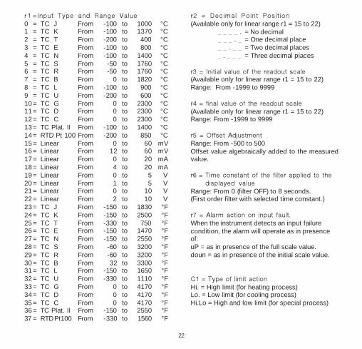
r1 =Input Type and Range Value0 = TC J From -100 to 1000 °C1 = TC K From -100 to 1370 °C2 = TC T From -200 to 400 °C3 = TC E From -100 to 800 °C4 = TC N From -100 to 1400 °C5 = TC S From -50 to 1760 °C6 = TC R From -50 to 1760 °C7 = TC B From 0 to 1820 °C8 = TC L From -100 to 900 °C9 = TC U From -200 to 600 °C10 = TC G From 0 to 2300 °C11 = TC D From 0 to 2300 °C12 = TC C From 0 to 2300 °C13 = TC Plat. II From -100 to 1400 °C14 = RTD Pt 100 From -200 to 850 °C15 = Linear From 0 to 60 mV16 = Linear From 12 to 60 mV17 = Linear From 0 to 20 mA18 = Linear From 4 to 20 mA19 = Linear From 0 to 5 V20 = Linear From 1 to 5 V21 = Linear From 0 to 10 V22 = Linear From 2 to 10 V23 = TC J From -150 to 1830 °F24 = TC K From -150 to 2500 °F25 = TC T From -330 to 750 °F26 = TC E From -150 to 1470 °F27 = TC N From -150 to 2550 °F28 = TC S From -60 to 3200 °F29 = TC R From -60 to 3200 °F30 = TC B From 32 to 3300 °F31 = TC L From -150 to 1650 °F32 = TC U From -330 to 1110 °F33 = TC G From 0 to 4170 °F34 = TC D From 0 to 4170 °F35 = TC C From 0 to 4170 °F36 = TC Plat. II From -150 to 2550 °F37 = RTD Pt100 From -330 to 1560 °F
r2 = Decimal Point Position(Available only for linear range r1 = 15 to 22)
_ _ _ _ . = No decimal_ _ _ . _ = One decimal place_ _ . _ _ = Two decimal places_ . _ _ _ = Three decimal places
r3 = Initial value of the readout scale(Available only for linear range r1 = 15 to 22)Range: From -1999 to 9999
r4 = final value of the readout scale(Available only for linear range r1 = 15 to 22)Range: From -1999 to 9999
r5 = Offset AdjustmentRange: From -500 to 500Offset value algebraically added to the measuredvalue.
r6 = Time constant of the filter applied to thedisplayed value
Range: From 0 (filter OFF) to 8 seconds.(First order filter with selected time constant.)
r7 = Alarm action on input fault.When the instrument detects an input failurecondition, the alarm will operate as in presenceof:uP = as in presence of the full scale value.doun = as in presence of the initial scale value.
C1 = Type of limit actionHi. = High limit (for heating process)Lo. = Low limit (for cooling process)Hi.Lo = High and low limit (for special process)

23
C2 = Rearming ModeO = Acknowledgements rearm (reset) the limiter
(and restart the process) only if the conditionwhich generated the shutdown status no longerexists (points A and C of the Example 1). It donot generate any effect if the condition whichgenerated the shutdown status still exists (pointB of the Example 1).
I = Acknowledgements enable the automaticrearmament (reset) of the limiter if thecondition which generated the shutdownstatus still exists (point B of the Example 2).(The instrument rearms (reset) automaticallywhen the condition which generated theshutdown status no longer exists).
Notes about limiter functionThe relay of the output 1 operates in fail-safemode (relay de-energized during shutdowncondition) and latching mode.
The OUT 1 turns OFF when:- C1 = Hi and the measured value is greater
than limiter threshold [“Su” parameter (seeOperative parameters”)] or
- C1 = LO and the measured value is less thanlimiter threshold [“Su” parameter (seeOperative parameters”)] or
- C1 = HiLO and the measured value is greaterthan “Su” parameter (see Operative param-eters”) or less than “S1” parameter (seeOperative parameters”).
The Out 1 remains OFF until the condition whichgenerated the shutdown, no longer exists and theacknowledge action has been performed.
The upper display flashes during a shutdown andreturns to a steady display when the shutdowncondition no longer exists.
When C2 =0 and OUT 1 is OFF, RESET LED is ON.When C2 = 1 one of the following condition mayoccur:- if no acknowledgement has been made, OUT 1
is OFF and the RESET LED is flashing;- if the acknowledgement has been made but the
condition which generated the shutdown statusstill exists, OUT 1 is OFF and the RESET LEDis steady ON.
The shutdown condition can be stored in permanentmemory (see C4).Acknowledgment can be performed by pressing theRESET key, by momentarily closing the external drycontact or by a command from the serial link.
The length of the shutdown condition and max/minmeasured values are stored in memory and avail-able for viewing until the next shutdown conditionoccurs. These informations are lost at power down.During a shutdown condition the max/minmeasured values are continuously updated andcan be monitored.
Example 1 - C1 = Hi and C2 = O
A, B, C = Acknowledgment actions.NOTE: Acknowledgment B has no effect.

24
Example 2 - C1 = Hi and C2 = 1
A, B = Acknowledgment actions.
C3 = Rearm at Power-upAuto = Automatic rearmn An = Manual rearm
C4 = Shutdown memory0 = The shutdown condition will be saved (at
next power up it will be reactivated)1 = The shutdown condition will be lost in
case of power down
C5 =Time Constant of the Filter appliedto the Measured Value for LimitAction.
Range: From 0 (filter OFF) to 8 secondsNote: First order filter with selected time constant.
P 1 = Alarm Function(Skipped when the option is not available)nonE = Not providedAL.P = Process alarmAL.b = Band alarmAL.d = Deviation alarmWhen C1 = Hi.Lo, “AL.b” and “AL.d” are notavailable.
P2 = Alarm configuration(Skipped if option is not available or P1 = none)H.A. = High alarm with automatic resetL.A. = Low alarm with automatic resetH.A.Ac = High alarm with automatic reset and
"Silence" function.L.A.Ac =Low alarm with automatic reset and
"Silence" function.H.L. = High alarm with manual resetL.L. = Low alarm with manual reset
NOTE:1) For band alarm, H.A./H.A.Ac/H.L. signifies
outside band alarm, while L.A./ L.A.Ac/L.L.signifies inside band alarm.
2) The "Silence" function allows the manual resetof the alarm even if the alarm condition is stillin progress.
Example for P2 = H.A.
* Alarm Status:Relay energized (P3 = dir)Relay de-energized (P3 =rEV)

25
Example for P2 = H.A.A.c
* Alarm Status: Relay energized (P3 = dir)Relay de-energized (P3 =rEV)
Example for P2 = H.L.
* Alarm Status:Relay energized (P3 = dir)Relay de-energized (P3 =rEV)
P3 = Alarm Action(Skipped if option not is available or P1 = none)dir = Direct action
(Relay energized in alarm condition)rEV = Reverse action
(Relay energized in non-alarm condition)
P4 = Alarm Standby (mask) Function(Skipped if option is not available or P1= none)OFF = Standby function disabledOn = Standby function enabled
If the alarm is programmed as band or deviation,this function masks the alarm condition at start upand after a “Su” (limit threshold) changement untilthe process variable reaches the alarm threshold,plus or minus hysteresis. This standby functionmasks a Process Alarm condition at start up untilthe process variable reaches the alarm thresholdplus or minus hysteresis.
PF = Time Constant of the Filter applied to theMeasured Value for Alarm Action
(Skipped if option is not available or P1 = none)Range: From 0 (filter OFF) to 8 seconds(First order filter with selected time constant.)

26
n1 = Safety Lock0 = UNLOCKed. The device is always
UNLOCKed and all parameters can bemodified.
l = LOCKed. The device is always LOCKedand no parameters can be modified
From 2 to 9999 = This number is a password, tobe used in run time (see “nn”), to LOCK/UNLOCK the device.
t1 = Timeout Selectiontn10 = 10 second timeouttn30 = 30 second timeout
d1 = Digital Input (contact closure)(This is a read only parameter)Enb = Digital input enableddlS = Digital input disabled(The digital input is used as a remoteAcknowledgment .)
The configuration procedure is now complete.The display will show "COnF".

27
Operating Mode
1) Remove the instrument from its case.2) Set switch V101 to the closed position. (See
illustrations at “Preliminary HardwareSettings”).
3) Re-insert the instrument in its case.4) Switch on the instrument.
Normal Display ModeOn powerup the device starts in the "Normal DisplayMode."
By pressing the or key, it is possible to changethe displayed information; therefore, one of thefollowing display modes can be selected:
1) The upper display shows the measured valuewhile the lower display shows the "Pu"(Process variable).If this display was active at power down, it willbe active at powerup.
2) The upper display shows the limiter thresholdwhile the lower display shows "Su." If thisdisplay was active at power down, it will beactive at powerup.
3) The upper display shows the second limiterthreshold while the lower display shows "S1."This information is available only if C1 = Hi.Lo.If this display was active at power down, it willbe active at powerup.
4) The upper display shows the total time(hh.mm) of the last shutdown condition whilethe lower displays shows “t.” If no shutdowncondition was detected, the upper display willshow “- - - -”. The information is lost atpower down and at powerup the device willdisplay the process variable.
5) The upper display shows the maximummeasured value detected during the lastshutdown condition while the lower displayshows "Ph.". If no shutdown condition wasdetected, the upper display will show “- - - -”.This information is not available if C1 = HI.Lo.The information is lost at power down and atpowerup the device will display the processvariable.
NOTE: When the shutdown condition wasgenerated by an input fault condition, the upperdisplay will indicate m.Err .
6) The upper display shows the minimummesured value detected during the lastshutdown condition while the lower displayshows "PL.” If no shutdown condition wasdetected, the upper display will show “- - - -”.This information is not available if C1 = Hi.The information is lost at power down and atpowerup the device will display the processvariable.
NOTE: When the shutdown condition wasgenerated by an input fault condition, theupper display will indicate m.Err
If, at power off, the device was in shutdowncondition and shutdown memoy function isselected (C4 = 0), and/or it was programmed formanual reset at startup (C3 = 1), then at the nextpower up the lower display will be flashing.

28
“RESET”= Press and hold for 1 second to rearm(reset) the limiter.
+ FUNC or + FUNCIncreases/decreases values at a higherrate when modifying parameters.
+ RESET or + RESETJumps to the Maximum or Minimumparameter value when modifyingparameters.
Operative Parameter Display ModeThe "FUNC" key initiates the Operative Param-eter Display Mode when pressed for less than 10seconds in the "Normal Display Mode."
The lower display shows the parameter code whilethe upper display shows the parameter value orstatus. The value of the selected parameter can bemodified with the and keys.
Press the "FUNC" key again to store the newvalue and advance to the next parameter.
If no keys are pressed within the timeout period(see t1), the instrument will automatically return tothe "Normal Display Mode" in the previous displayand any modification of the last displayedparameter will be lost.
All parameters (except ) can be modified onlywhen the device is UNLOCKed.
The LOCK/UNLOCK status can be selected inconfiguration using “n1” parameter or during theoperating mode with the “nn” parameter(password).
Indicators“RESET“ =Indicates control output 1 status as
follows:a) When C2 parameter has been
configured equal to 0,LED ON when Output 1 is OFFLED OFF when Output 1 is ON
b) When C2 parameter has beenconfigured equal to 1,LED flashes when Output 1 is OFFLED ON when Output 1 is OFF andacknowledgedLED OFF when Output is ON
“ALM” = Indicates alarm status as follows:- Flashes when alarm is ON- ON when alarm has been resetted but
the alarm condition is still present.- OFF when alarm is OFF
“REM” = Indicates the remote status of theinstrument.- Flashes when instrument is in remote
mode.- OFF when instrument is in local mode.
Key Functions in Normal Display Mode“FUNC” = By pressing it, the display changes from
“Normal Display Mode” to “OperativeParameter Display Mode.”
= Pressing it for more than ten secondsinitiates the Lamp Test. During the LampTest the device functions normally whileall display segments and LED's are litwith a 50% duty cycle. No timeout isapplied to a lamp test.Press the "FUNC" key again to end theLamp Test.
" " or “ " = By pressing these keys it ispossible to change the displayedinformation. See “Normal DisplayMode.”

29
To switch from LOCKED to UNLOCKED, assignto the “nn” parameter a value equal to the “n1”parameter setting. To switch from UNLOCKED toLOCKED, assign to the “nn” parameter anynumber other than the n1 parameter setting.When the device is in remote mode (the serial linkcontrols the device) no parameters can be modified.
Key Functions inOperative Parameter Display Mode
FUNC = Pressing the “FUNC” key, theinstrument stores the new setting(if changed) and goes to the nextparameter.
or = Changes the setting of theselected parameter.
RESET = Press and hold for more than 1second for limiter rearmament.
OPERATING PARAMETERSSome of the following parameters may not appear,depending on the configuration.
Lower DescriptionDisplay
Manual reset of the alarm.(Available only if P1 = AL.p, AL.b or AL.d)ON = Starts the manual reset of the alarmOFF = Do not start the alarm reset.Select ON and press the FUNC key inorder to reset the alarm.After a manual reset of the alarm theinstrument returns in Normal Display Mode.
nn Software Key(Skipped if n1 = 0 or 1)ON = the device is LOCKED.OFF = the device is UNLOCKED.When it is desired to switch from LOCKto UNLOCK condition, set a value equalto “n1” parameter.When it is desired to switch fromUNLOCK to LOCK condition, set a valuedifferent from “n1” parameter.
Su Limiter ThresholdRange: Span limits (From "S1" to full scalevalue when C1 = Hi.Lo)
S1 Second Limiter Threshold(Available when C1 = Hi.Lo)Range: From initial scale value to "Su"
HS Limiter HysteresisRange: From 0.1% to 10.0% of theinput span or 1 LSD
AL Alarm Threshold (optional)(Available only if the option is fitted andP1= AL.P, AL.b or AL.d.)Ranges:span limits for process alarm (P1 = AL.P)from 0 to 500 for band alarm (P1 = AL.b)from -500 to 500 for deviation alarm(P1 = AL.d)
HA Alarm Hysteresis (optional)(Available only if the option is fitted andP1 = AL.P, AL.b or AL.d)Range: From 0.1% to 10.0% of the inputspan or 1 LSD.

30
Limiter functionThe relay of the output 1 operates in fail-safemode (relay de-energized during shutdowncondition) and latching mode.
The OUT 1 turns OFF when:- The instrument is configured as a high limiter
(C1 = Hi) and the measured value is greaterthan limiter threshold [“Su” parameter (seeOperative parameters”)] or
- The instrument is configured as a low limiter(C1 = LO) and the measured value is lessthan limiter threshold [“Su” parameter (seeOperative parameters”)] or
- The instrument is configured as a high/lowlimiter (C1 = HiLO) and the measured value isgreater than “Su” parameter (see Operativeparameters”) or less than “S1” parameter (seeOperative parameters”).
The Out 1 remains OFF until the condition whichgenerated the shutdown, no longer exists and theacknowledge action has been performed.
The upper display flashes during a shutdown andreturns to a steady display when the shutdowncondition no longer exists.
When the OUT 1 is OFF the RESET LED is ON [if theselected rearming mode is equal to 0 (C2 = 0)] orflashes [if the selected rearming mode is equal to 1(C2 = 1)].When the selected rearming mode is equal to 1(C2 = 1) the RESET LED is steady ON whenOUT 1 is OFF and acknowledged.The shutdown condition can be stored in permanentmemory (see C4).Acknowledgment can be performed by pressing theRESET key, by momentarily closing the external dry
contact or by a command from the serial link.The length of the shutdown condition and max/minmeasured values are stored in memory and availablefor viewing (see “Normal Display Mode”) until the nextshutdown condition occurs.These informations are lost at power down.
During a shutdown condition the max/min meas-ured values are continuously updated and can bemonitored.
Example 1 - C1 = Hi and C2 = O
Example 2 - C1 = Hi and C2 = 1

31
Alarm functions(Skipped if option is not available or P1 = none)The alarm can be programmed as:- process alarm- band alarm- deviation alarm.Band and deviation alarms are referred to thelimiter threshold and are possible only if an highlimiter or a low limiter function has been selected.For all the alarm types, it is possible to selectautomatic or manual reset or the “Silence”function.The "Silence" function is a typical function of thealarm annunciators (see ISA “Alarm annunciatoroperational sequence”) and it is usually applied toaudible alarm indications (horn). This functionallows the manual reset of the alarm even if thealarm condition is still in progress.
It is also possible to assign to the alarm a standby (mask) function.If the alarm is programmed as band or deviationalarm, this function masks the alarm conditionafter a safety threshold change or at theinstrument start-up until process variable reachesthe alarm threshold plus or minus hysteresis. Ifthe alarm is programmed as a process alarm, thisfunction masks the alarm condition at instrumentstart-up until process variable reaches the alarmthreshold plus or minus hysteresis.Graphic example of the alarm behaviour areshown at pages 12 and 13.
Serial LInk (optional)The device can be connected to a host computer viaserial link.
The host can put the device in LOCAL (parametersare controlled via keyboard) or in REMOTE (func-tions and parameters are controlled via serial link).REMOTE is shown by the decimal point to theleft of "REM" which is on the right side of thenumeric display.
Via serial link it is possible to read and/or to modifyall the operative and configuration parameters.The following conditions must apply to implementthis function:1) Configure parameters L1 through L4 with the
front keyboard2) The device must be in the Operating mode.

32
Error Messages
Overrange, Underrange andSensor Break IndicationsThis device detects input fault conditions.(OVERRANGE, UNDERRANGE OR SENSORBREAK). When the process variable exceeds thespan limits an OVERRANGE condition will appearas:
An UNDERRANGE condition will appear as:
A sensor break is signaled as "OPEn”. On the mA/V input, a sensor break can be detected only whenthe range selected has a zero elevation (4/20 mA,12/60 mV, 1/5 V or 2/10 V.)
On the RTD input "shrt" is signalled when inputresistance is less than 15 Ω (short circuit sensordetection).
This device detects reference junction errors orerrors on the internal autozero measurement. Whena fault is detected the output goes OFF and thealarm assumes an upscale/downscale reading inaccordance with r7.
Error MessagesOn powerup, the instrument performs a self-diag-nostic test. When an error is detected, the lowerdisplay shows an "Er" indication while the upperdisplay shows the code of the detected error.
Error List100 Error in EEPROM writing150 Short circuit on CPU's outputs200 Error on "protect register" in EEPROMXXX Configuration parameter error.301 Error on calibration of selected input.307 rj input calibration error.400 Error on operative parameters.500 Error on autozero measurement.502 Error on reference junction measurement.510 Error during calibration procedure.
Dealing with Error Messages1) When a configuration parameter error is
detected, repeat the configuration procedure ofthat specific parameter.
2) If an error 400 is detected, simultaneouslypress the t and s keys to load the defaultparameters and then repeat the controlparameter setup.
3) For all other errors, contact yourService Representative.

33
General Specifications
Case: Polycarbonate grey caseSelf extinguishing degree: V-0 according to UL.Front protection - designed and tested for IP 65 (*)and NEMA 4X (*) for indoor locations (when panelgasket is installed).(*) Test were performed in accordance with IEC529, CEI 70-1 and NEMA 250-1991 STD.Installation: panel mounting.Rear terminal board: 15 screw terminals (screwM3, for cables from ø 0.25 to ø 2.5 mm2 or fromAWG 22 to AWG 14 ), connection diagram andsafety rear cover.Dimensions: 48 x 48 mm (according to DIN43700); depth- 122 mm for models with RS-485.- 105 mm for models without RS-485Weight: 250 g. max. (8.75 oz.).Power supply : (switching mode) from 100 to240 V AC. 50/60 Hz (+10 % to -15 % of thenominal value) or24 V DC/AC (+10 % of the nominal value).Power consumption: 8 VA.Insulation resistance: > 100 MΩ according toIEC 1010-1.Isolation voltage: 1500 V r.m.s. according to IEC1010-1.Common mode rejection ratio:120 dB @ 50/60 Hz.Normal mode rejection ratio: 60 dB @ 50/60 Hz.Electromagnetic compatibility:This instrument is marked CE.Therefore, it is conforming to council directive 89/336/EEC (reference harmonized standard EN-50081-2 and EN-50082-2).
Safety requirements:This instrument is marked CE.Therefore, it is conforming to council directives73/23/EEC and 93/68/EEC (reference harmonizedstandard EN 61010-1).Installation cathegory: IID/A conversion: dual slope integration.Sampling time :- for linear inputs = 250 ms.- for TC or RTD inputs = 500 ms.Display updating time: 500 ms.Resolution: 30000 counts.Temperature Drift- Less than 200 ppm/°C of full span for mV and
TC ranges 0, 1, 3, 4, 8, 13, 23, 24, 26, 27, 31,36 (CJ excluded).
- Less than 300 ppm/°C of full span for mA, V andTC ranges 10, 11, 12, 33, 34, 35 (CJ excluded)
- Less than 400 ppm/°C of full span for RTD and TCrange 9, 32 (CJ excluded).
- Less than 500 ppm/°C of full span for TC ranges2, 5, 6, 25, 28, 29 (CJ excluded).
- Less than 600 ppm/°C of full span for TC ranges7, 30.NOTE: Precision and drift guaranteed (forT>300°C/570°F).
Accuracy: + 0.2% f.s.v. @ 25 °C (77 °F) andnominal power supply voltage.Operative temperature: from 0 to +50 °C (32 to122 °F).Storage temperature: from -20 to +70 °C (-4 to158 °F).Humidity: from 20% to 85 % RH notcondensing.

34
INPUTS
A) THERMOCOUPLEType : J, K, T, E, N, S, R, B, L, U, G(W), D(W3),C(W5), Platinel II, °C/°F selectable.External resistance: 100 Ω max, maximumerror 0.1% of span.Burn out: It is shown as an overrange condition(standard). It is possible to obtain an underrangeindication by cut and short.Cold junction: automatic compensation from 0 to50 °C.Cold junction accuracy : 0.1 °C/°CInput impedance: > 1 MΩCalibration : according to IEC 584-1 and DIN43710 - 1977.STANDARD RANGES TABLE
(*) P. equal to Platinel II
B) RTD (Resistance Temperature Detector)Input: for RTD Pt 100 Ω, 3 wire connection.Input circuit: current injection.°C/°F selection: via front pushbuttons or serial link.Line resistance: automatic compensation up to 20Ω/wire with no measurable error.Calibration: according to DIN 43760Burn out : The instrument detect the open conditionof one or more wires. It is able to detect also theshort circuit of the sensor.
STANDARD RANGES TABLE
C) LINEAR INPUTSRead-out: keyboard programmable between-1999 and +9999.Decimal point: programmable in any positionBurn out: the instrument shows the burn outcondition as an underrange condition for 4-20mA, 1-5 V and 2-10 V input types.It shows the burn out condition as an underrangeor an overrange condition (selectable bysoldering jumper) for 0-60 mV and 12-60 mVinput types. No indication are available for 0-20mA, 0-5 V and 0-10 V input types.
Inputtype Ranges
- 200 / 850 °C
- 330 / 1560 °F
14
37
RTD Pt 100 W
DIN 43760T/Ctype
Ranges
0123456789
10111213
2324252627282930313233343536
JKTENSRBLU
G(W)D(W3)C(W5)P.(*)
-150 / 1830 °F-150 / 2500 °F-330 / 750 °F-150 / 1470 °F-150 / 2550 °F
-60 / 3200 °F-60 / 3200 °F32 / 3300 °F
-150 / 1650 °F-330 / 1110 °F
0 / 4170 °F0 / 4170 °F0 / 4170 °F
-150 / 2550 °F
-100 / 1000 °C-100 / 1370 °C-200 / 400 °C-100 / 800 °C-100 / 1400 °C
-50 / 1760 °C-50 / 1760 °C
0 / 1820 °C-100 / 900 °C-200 / 600 °C
0 / 2300 °C0 / 2300 °C0 / 2300 °C
-100 / 1400 °C

35
STANDARD RANGES TABLE
D) LOGIC INPUTSThis instrument is provided of 1 logic input usedfor remote acknowledgement.NOTES1) Use an external dry contact capable of
switching 0.5 mA, 5 V DC.2) The instrument needs 100 ms to recognize a
contact status variation.3 ) The logic inputs are NOT isolated by the
measuring input.
OUTPUTS
Output updating time :- 250 ms when a linear input is selected- 500 ms when a TC or RTD input is selected.
OUTPUT 1Type: relay SPDT contact .Contact rated: 3 A at 250 V AC on resistive load.Function: Safety limiter output.Action: reverse (fail-safe).
OUTPUT 2Type: relay SPST contact .Contact rated: 2 A at 250 V AC on resistive load.Function: Alarm outputAction: direct/reverse programmable by front
keyboard.
ALARM
Action: Direct or reverse acting.Alarm functions: configurable as process alarm,band alarm or deviation alarm.Alarm reset: automatic reset, manual reset or"Silence" function is programmable.Stand by (mask) alarm: the alarm can beconfigured with or without stand by (mask)function.
Process alarm:Operative mode : High or low programmable.Threshold : programmable in engineering unit withinthe readout span.Hysteresis: programmable from 0.1 % to 10.0 % ofthe readout span.
Input type
1516171819202122
0 - 60 mV12 - 60 mV 0 - 20 mA 4 - 20 mA
0 - 5 V1 - 5 V0 - 10 V2 - 10 V
impedance
> 1 MΩ
< 5 Ω
> 400 kΩ
> 400 kΩ
Accuracy
0.2 % + 1 digit@ 25°C(77 °F)
36
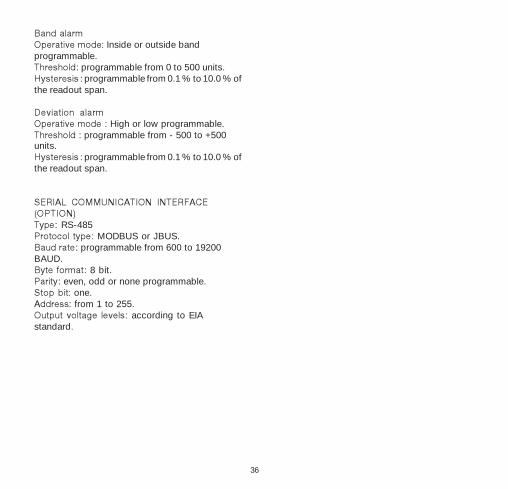
Band alarmOperative mode: Inside or outside bandprogrammable.Threshold: programmable from 0 to 500 units.Hysteresis : programmable from 0.1 % to 10.0 % ofthe readout span.
Deviation alarmOperative mode : High or low programmable.Threshold : programmable from - 500 to +500units.Hysteresis : programmable from 0.1 % to 10.0 % ofthe readout span.
SERIAL COMMUNICATION INTERFACE(OPTION)Type: RS-485Protocol type: MODBUS or JBUS.Baud rate: programmable from 600 to 19200BAUD.Byte format: 8 bit.Parity: even, odd or none programmable.Stop bit: one.Address: from 1 to 255.Output voltage levels: according to EIAstandard.

37
CalibrationCalibration parameters are logically divided intogroups of two parameters each – initial scalevalue and final scale value. A calibration checkis provided after entering the values of eachgroup. A calibration check can be initiated with-out making an entry: press the FUNC key to ad-vance to the desired calibration check. The lowerdisplay will show the parameter code (t., rJ., etc.)and the upper display will show “on” or “off.”Press the s or t key to select on or off.
To go to the next parameter without modifyingthe calibration, press the FUNC key when thedisplays shows “off.” To return the previous pa-rameter without modifying the calibration, pressthe MAN key.
To set the parameter calibration, press the FUNCkey when the display shows “on.” The displaywill blank, and only the decimal point of the LSDof the lower display will be lit during the calibra-tion step.
Before beginning calibration, be sure internalswitch V101 is open (see "Preliminary HardwareSettings").
General Guidelinesa) Instrument should be mounted in its case
in order to keep internal temperatureconstant.
b) Ambient temperature should be stable.Avoid drift due to air conditioning or othermechanical devices.
c) Relative humidity should not exceed 70%.
d) Minimum warm up time should be at least20 minutes.
e) Operate as much as possible in a noisefree environment.
f) During calibration, connect one input at atime to the rear terminal block.
g) Before input calibration, the specificsettings described in the PreliminaryHardware Settings section must be made.
h) Use calibrators with the following:AccuracyCurrent Input:
±0.025% output±0.0025% range±0.01 microamp
Voltage Input:±0.005% output±0.001% range±5 microvolt
TC Input:±0.005% output±0.001% range±5 microvolt
RTD Input:±0.02%±0.0025 ohm/decade
Reference Junction Compensation:better than 0.1°C
mA output: better than ±0.1% of thereadout ±2 microamp
ResolutionCurrent Input: 0.5 microampVoltage Input: 100 microvoltTC Input: 1 microvoltRTD Input: 10 milliohmRef. Jct. Compensation: better than 0.1°CmA output 1 microamp

38
Calibration ParametersFollowing is a complete list of calibration sym-bols:CodeParametertL TC/mV Input Minimum Range ValuetH TC/mV Input Maximum Range Valuet. TC/mV Input CheckrJ Reference Junction CompensationrJ. Reference Junction Compensation Check
(in 1/10°C; Reset LED lit)PL RTD Input Minimum Range ValuePH RTD Input Maximum Range ValueP. RTD Input CheckAL Current Input Minimum Value (0 mA)AH Current Input Maximum Value (20 mA)A. Current Input ChecknL 5 Volt Input Min. Range Value (0 V)nH 5 Volt Input Max Range Value (5 V)n. 5 Volt Input CheckUL 10 Volt Input Minimum Value (0 V)UH 10 Volt Input Maximum Value (10 V)U. 10 Volt Input Check
ProcedureSet the internal DIP switches as explained in thePreliminary Hardware Settings section of thismanual. Perform calibration procedures accord-ing the jumpers positions, otherwise the storedcalibration value might be lost.
Switch on the instrument; the upper display willshow “COnF”. Press the s key and the displaywill show “CAL”. Press the “FUNC” key to startthe calibration process. Repeatedly press theFUNC key until the desired calibration (parameter)code appears.
Use the s and t keys to select between ONand OFF. To go to the next parameter withoutmodifying the calibration, press the FUNC keywhen the display shows “OFF” .
tL TC/mV input minimum range valuea) Perform the preliminary hardware settings.
Connect the calibrator and instrument asshown below.
P an e l m o un ted co n tro lle r
W a ll o r R a ilm o un te d co n tro lle r
10
9
10
9
10
9
10
9
15
14 fo r Ty pe s G , D , C , B , R , S
11 fo r Ty pe s J , K , L, N , T, E , U , P lat in el
b) The displays show “OFF” and “tL”.c) Set calibrator to 0.000 mV.d) Press the s key; display changes to “ON”.e) After a few seconds, start calibration by
pressing the FUNC key. The decimal pointof the least significant digit will light toindicate the instrument is performing thecalibration. When calibration is complete,the instrument will proceed to the nextparameter.

39
tH TC/mV input maximum range valuea) Set the calibrator to 60.000 mV.b) Press the s key; the displays will show
“ON” and “tH”.c) After a few seconds, start calibration by
pressing the FUNC key. The decimal pointof the least significant digit will light toindicate the instrument is performing thecalibration. When this calibration iscomplete, the instrument will proceed tothe next parameter.
t. TC/mV input checkThe display will show “t.” followed by a numbershowing the measured value in counts.
Check the linear calibration by setting:a) 0.000 mV; the readout must be equal to
“t.0 0000” ±10 counts.b) 60.000 mV; the readout must be equal to
“t.3 0000” ±10 counts.c) 30.000 mV; the readout must be equal to
“t.1 5000” ±10 counts.d) Press the FUNC key; go to the next
parameter.
rJ Reference junction compensationNote: Make sure tL and tH are correctly calibratedbefore attempting rJ calibration.a) Measure the temperature close to terminals
9 and 10 using an appropriate instrument,as shown below.
15
1 4 fo r Typ es G , D , C , B , R , S
M eas ur ing D ev ice
+
-
W a ll o r R a il M ou nte d Co ntro lle r
10
9
M eas ur ing D ev ice
+
-
P an e l M o u n te d C on tro lle r
1 1 fo r Typ es J , K , L, N , T, E , U , Pla tine l
b) Wait a few minutes to allow temperaturestabilization of the entire system (compen-sation cable, sensor, calibrator andinstrument).
c) The displays will show “rJ” and “OFF.” Usethe s and t keys to make the readoutvalue equal to the temperature measuredby the measuring device in tenths ofdegree Celsius.
d) After a few seconds, start calibration bypressing the FUNC key. The decimal pointof the least significant digit will light toindicate the instrument is performing the

40
calibration. When this calibration iscomplete, the instrument will proceed tothe next parameter.
rJ. Reference junction compensation checkThe display will show “rJ.” and the temperaturein tenths of °C. Check that the display readoutis equal to the value read by the measuring de-vice.
Press the FUNC key; the instrument will proceedto the next parameter.
PL RTD input minimum range valuea) Perform the preliminary hardware settings.
Connect the calibrator and instrument asshown below.
1 0
8
9
1 5
1 6
1 4
P an el M o un ted C on tro lle r
W all o r Ra il M o u nted C o n tro lller
b) Set 0.00 ohms on the resistor box.c) Press the s key; the displays show “ON”
and “PL”.d) After a few seconds, start calibration by
pressing the FUNC key. The decimal point
of the least significant digit will light toindicate the instrument is performing thecalibration. When this calibration iscomplete, the instrument will proceed tothe next parameter.
PH RTD input maximum range valuea) Set resistor box to 375.00 ohms.b) Press the s key; the displays will show
“ON” and “PH”.c) After a few seconds, start calibration by
pressing the FUNC key. The decimal pointof the least significant digit will light toindicate the instrument is performing thecalibration. When this calibration iscomplete, the instrument will proceed tothe next parameter.
P. RTD input checkThe display shows “P.” followed by a numbershowing the measured value in counts.
Check the calibration (not linear) by setting theresistance box to:a) 0.00 ohms; the readout should be
“P. 0 0000” ±10 counts.b) 125.00 ohms; the readout should be
“P.1 0190” ±10 counts.c) 250.00 ohms; readout should be
“P. 2 0189” ±10 counts.

41
d) 375.00 ohms; readout should be“P. 3 0000” ±10 counts.
e) Press the FUNC key and proceed to nextparameter.
AL Current input (mA) minimum range valuea) Perform the preliminary hardware settings.
Connect the calibrator and instrument asshown:
P ane l m o u n te d co n trol le r
W a ll o r R a i lm o un ted c on tro l le r
10
9
10
9
10
9
10
9
15
14
b) Set 0.000 mA on the calibrator (even if theminimum range value is 4 mA). The upperdisplay shows “OFF.”
c) Press the s key, the display will switch to“ON”.
d) After a few seconds, start calibration bypressing the FUNC key. The decimal pointof the least significant digit will light toindicate the instrument is performing thecalibration. When this calibration iscomplete, the instrument will proceed tothe next parameter.
AH Current input (mA) maximum range valuea) Set 20 mA on the calibrator.b) Press the s key, the displays will show
“AH” and “ON”.c) After a few seconds, start calibration by
pressing the FUNC key. The decimal pointof the least significant digit will light toindicate the instrument is performing thecalibration. When this calibration iscomplete, the instrument will proceed tothe next parameter.
A. Current input (mA) checkThe display will show “A.” followed by a numbershowing the measured value in counts.
Check the linear calibration by setting the cali-brator to:a) 0.000 mA; the readout should be
“A. 0 0000” ±10 counts.b) 20.000 mA; readout should be
“A. 3 0000” ±10 counts.c) 10.000 mA; readout should be
“A. 1 5000” ± 10 counts.d) Press the FUNC key.

42
nL 5 volt input-minimum range valuea) Perform the preliminary hardware settings.
Connect the calibrator and instrument asshown:
P an e l m ou n te d co n trol le r
W a l l o r R a i lm o un te d c on tro l le r
10
9
10
9
10
9
10
9
15
14
b) Set 0.000 V on the calibrator (even if theminimum range value is 1 V). The upperdisplay will show “OFF.”
c) Press the s key, the display will show “nL”and “ON.”
d) After a few seconds, start calibration bypressing the FUNC key. The decimal pointof the least significant digit will light toindicate the instrument is performing thecalibration. When this calibration iscomplete, the instrument will proceed tothe next parameter.
nH 5 volt input-maximum range valuea) Set 5.000 V on the calibrator.b) Press the s key, the display will show “nH”
and “ON”.c) After a few seconds, start calibration by
pressing the FUNC key. The decimal pointof the least significant digit will light toindicate the instrument is performing thecalibration. When this calibration iscomplete, the instrument will proceed tothe next parameter
n. 5 volt input checkThe display will show “n.” followed by a numbershowing the measured value in counts.
Check the calibration by setting the calibrator to:a) 0.000 V; the readout should be
“n. 0 0000” ±10 counts.b) 5.000 V; readout should be
“n. 3 0000” ±10 counts.c) 2.500 V; readout should be
“n. 1 5000” ± 10 counts.d) Press the FUNC key to proceed to next
parameter.

43
UL 10 volt input - minimum range valuea) Perform preliminary hardware settings as
described in the Configuration section.Connect the instrument to the calibrator asshown:
P ane l m o u n te d co n trol le r
W a ll o r R a i lm o un ted c on tro l le r
10
9
10
9
10
9
10
9
15
14
b) Set 0.000 V on the calibrator (even if theminimum range value is 2 V). The upperdisplay will show “OFF”.
c) Press the s key to enable calibration. Theupper display will switch to “ON”.
d) Wait a few seconds until the measurementhas stabilized, then push the FUNC key.When calibration is complete, the instru-ment will go to the next parameter.
UH 10 volt input-maximum range valuea) Set 10.000 V on the calibrator.b) Press the s key, the display will show
“UH” and “ON”.c) After a few seconds, start calibration by
pressing the FUNC key. The decimal pointof the least significant digit will light toindicate the instrument is performing thecalibration. When this calibration iscomplete, the instrument will proceed tothe next parameter
U. 10 volt input checkThe display will show “U.” followed by a numbershowing the measured value in counts.
Check the calibration (linear) by setting the cali-brator to:a) 0.000 V; the readout should be
“U.0 0000” ±10 counts.b) 10.000 V; readout should be
“U.3 0000” ±10 counts.c) 5.000 V; readout should be
“U.1 5000” ±10 counts.d) Press the FUNC key.

44
Maintenance
1) REMOVE POWER FROM THE POWER SUPPLYTERMINALS AND FROM RELAY OUTPUTTERMINALS
2) Remove the instrument from case.3) Using a vacuum cleaner or a compressed air jet
(max. 3 kg/cm2) remove all deposit of dust and dirtwhich may be present on the louvers and on theinternal circuits trying to be careful for not damagethe electronic components.
4) To clean external plastic or rubber parts use only acloth moistened with:- Ethyl Alcohol (pure or denatured) [C2H5OH] or- Isopropil Alcohol (pure or denatured)[(CH
3)2CHOH] or
- Water (H2O)
5) Verify that there are no loose terminals.6) Before re-inserting the instrument in its case, be
sure that it is perfectly dry.7) re-insert the instrument and turn it ON.
This completes the calibration procedure. Toenter the configuration procedure press the skey, the display will show "CnF". If configurationand calibration are complete, switch the instru-ment off and set the DIP switches according thePreliminary Hardware Settings.
Appendix A.45
APPENDIX A
Default parameters
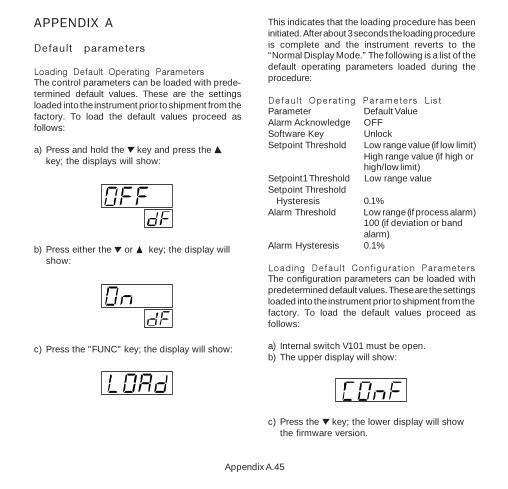
Loading Default Operating ParametersThe control parameters can be loaded with prede-termined default values. These are the settingsloaded into the instrument prior to shipment from thefactory. To load the default values proceed asfollows:
a) Press and hold the key and press the key; the displays will show:
b) Press either the or key; the display willshow:
c) Press the "FUNC" key; the display will show:
This indicates that the loading procedure has beeninitiated. After about 3 seconds the loading procedureis complete and the instrument reverts to the“Normal Display Mode.” The following is a list of thedefault operating parameters loaded during theprocedure:
Default Operating Parameters ListParameter Default ValueAlarm Acknowledge OFFSoftware Key UnlockSetpoint Threshold Low range value (if low limit)
High range value (if high orhigh/low limit)
Setpoint1 Threshold Low range valueSetpoint Threshold Hysteresis 0.1%Alarm Threshold Low range (if process alarm)
100 (if deviation or bandalarm)
Alarm Hysteresis 0.1%
Loading Default Configuration ParametersThe configuration parameters can be loaded withpredetermined default values. These are the settingsloaded into the instrument prior to shipment from thefactory. To load the default values proceed asfollows:
a) Internal switch V101 must be open.b) The upper display will show:
c) Press the key; the lower display will showthe firmware version.

Appendix A.46
.ARAP 1elbaT 2elbaT
naeporuE naciremA
1L SUbn subn
2L 1 1
3L 00291 00291
4L E8 E8
1rJepyT
0001ot001-()C°
JepyT0381ot051-(
)F°
2r .---- .----
3r 001- 051-
4r 0001 0381
5r 0 0
6r dnoces1 dnoces1
7r Pu Pu
1c iH iH
2c 1 0
3c otuA otuA
4c 0 0
5c dnoces1 dnoces1
1P Enon Enon
2P .A.H cA.A.H
3P VEr VEr
4P FFO FFO
FP dnoces1 dnoces1
1n 0 0
1t sdnoces01 sdnoces03
d) Still holding the key, press the key; thedisplay will show:
e) Press the key to select Table 1 (European)or Table 2 (American) default parameters; thedisplay will show:
f) Press the FUNC key; the display will show:
This indicates that the loading procedure has beeninitiated. After about 3 seconds the procedure iscomplete and the instrument reverts to the “COnF”display. The following is a list of the defaultconfiguration parameters loaded during theprocedure:

Appendix B.47
APPENDIX B
Thermocouple Compensating Cable Color Codes.
ThermocoupleMaterial
T Copper Constantan
J/L Iron Constantan
K Nickel ChromiumNickel Aluminum
R Platinum/Platinum13% Rhodium
S Platinum/Platinum10% Rhodium
E ChromelConstantan
B Platinum 30% RhPlatinum 6% Rh
N Nicrosil / Nisil
BritishBS 1843
+ White- Blue
Blue+ Yellow- Blue
Black+ Brown- Blue
Red+ White- Blue
Green+ White- Blue
Green+ Brown- Blue
Brown––
–
AmericanANSI MC 96.1
+ Blue- Red
Blue+ White- Red
Black+ Yellow- Red
Yellow+ Black- Red
Green+ Black- Red
Green+ Violet- Red
Violet+ Grey- Red
Grey–
GermanDIN 43710
+ Red- Brown
Brown+ Red- Blue
Blue+ Red- Green
Green+ Red- White
White+ Red- White
White––
––––
FrenchNFE 18-001+ Yellow- Blue
Blue+ Yellow- Black
Black+ Yellow- Purple
Yellow+ White- Green
Green+ White- Green
Green––
––––

Eurotherm/Barber-Colman741-F Miller DriveLeesburg, VA 20175
Telephone: +1 703 443 0000Facsimile: +1 703 669 1300Email: [email protected]
Copyright © 1998 Barber-Colman Company.