Embed Size (px)
Citation preview
Part _51128 Date 01/25/2006
INSTRUCTION MANUAL For RELAY TEST SET Model SR-98 The SR-98 includes a ROM-resident computer program. This program
belongs to Megger Corporation and contains trade secret ideas and information of Megger Corporation. To the extent this program contains ideas, Megger Corporation intends to protect and enforce its rights under state law. To the extent the program is deemed to constitute a form of expression of idea, Megger Corporation intends to protect and enforce its rights under the Copyright Act of 1976. The Statutory Copyright notice has been affixed hereto in the event that it is later determined that the program has been published within the meaning of the Copyright Act of 1976.
It is essential that this instruction book be read thoroughly before
putting the equipment in service.
REVISION HISTORY Revision ECN # Date 0 Initial Release 11/19/1998 1 28954 07/31/2001 2 29143 12/20/2001 3 29447 11/20/2002 4 30248 01/25/2006
COMMENTS Any comments or suggestions regarding the use of this test instrument or instruction manual would be appreciated. Send your comments to Megger, T M & S Department, 4271 Bronze Way, Dallas, TX 75237
IMPORTANT The information and data contained within this instruction manual are proprietary with Megger. The equipment described herein may be protected by one or more U.S. letters patent. MEGGER specifically reserves to itself all rights to such proprietary information as well as all rights under any such patent, none of which is waived by the submission of this instruction manual to anyone. The recipient, if a Government agency, acknowledges that this instruction book and the equipment described were procured with "Limited Rights" to technical data as described in ASPR 9-203 (b).
Copyright Megger, 1998, 2001,2006
SAFETY PRECAUTIONS
WARNING: VOLTAGES GENERATED BY THIS INSTRUMENT CAN BE HAZARDOUS
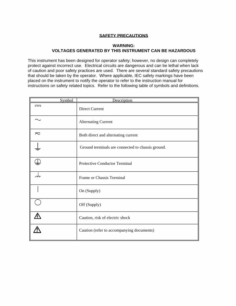
This instrument has been designed for operator safety; however, no design can completely protect against incorrect use. Electrical circuits are dangerous and can be lethal when lack of caution and poor safety practices are used. There are several standard safety precautions that should be taken by the operator. Where applicable, IEC safety markings have been placed on the instrument to notify the operator to refer to the instruction manual for instructions on safety related topics. Refer to the following table of symbols and definitions.
Symbol Description
Direct Current
Alternating Current
Both direct and alternating current
Ground terminals are connected to chassis ground.
Protective Conductor Terminal
Frame or Chassis Terminal
On (Supply)
Off (Supply)
Caution, risk of electric shock
Caution (refer to accompanying documents)
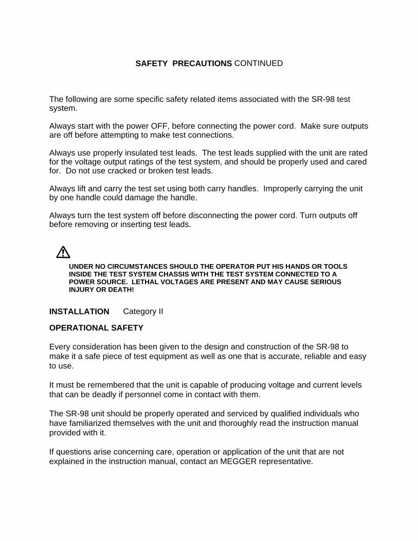
SAFETY PRECAUTIONS CONTINUED The following are some specific safety related items associated with the SR-98 test system. Always start with the power OFF, before connecting the power cord. Make sure outputs are off before attempting to make test connections. Always use properly insulated test leads. The test leads supplied with the unit are rated for the voltage output ratings of the test system, and should be properly used and cared for. Do not use cracked or broken test leads. Always lift and carry the test set using both carry handles. Improperly carrying the unit by one handle could damage the handle. Always turn the test system off before disconnecting the power cord. Turn outputs off before removing or inserting test leads.
UNDER NO CIRCUMSTANCES SHOULD THE OPERATOR PUT HIS HANDS OR TOOLS
INSIDE THE TEST SYSTEM CHASSIS WITH THE TEST SYSTEM CONNECTED TO A POWER SOURCE. LETHAL VOLTAGES ARE PRESENT AND MAY CAUSE SERIOUS INJURY OR DEATH!
INSTALLATION Category II OPERATIONAL SAFETY Every consideration has been given to the design and construction of the SR-98 to make it a safe piece of test equipment as well as one that is accurate, reliable and easy to use. It must be remembered that the unit is capable of producing voltage and current levels that can be deadly if personnel come in contact with them. The SR-98 unit should be properly operated and serviced by qualified individuals who have familiarized themselves with the unit and thoroughly read the instruction manual provided with it. If questions arise concerning care, operation or application of the unit that are not explained in the instruction manual, contact an MEGGER representative.
i
TABLE OF CONTENTS
THEORY OF OPERATION........................................................................................................................... 1 UNIT PANEL ILLUSTRATION ........................................................................................................ 1
DESCRIPTION OF CONTROLS AND INSTRUMENTATION ..................................................................... 2 INPUT POWER................................................................................................................................ 6 DISPLAY SCREENS ....................................................................................................................... 8
POWER UP SCREEN ........................................................................................................ 8 TEST MENU Screen .......................................................................................................... 8 ABOUT MENU.................................................................................................................... 9 LANGUAGE SELECTION Screen..................................................................................... 9 TIMER SETUP Screen ..................................................................................................... 10
DESCRIPTION OF TEST SCREENS............................................................................................ 12 CURRENT RELAY Test Screen...................................................................................... 13 IMPEDANCE RELAY Test Screen.................................................................................. 16 DIRECTIONAL RELAY Test Screen............................................................................... 17 DC RELAY Test Screen .................................................................................................. 17 METERING Screen .......................................................................................................... 18 VOLTAGE RELAY Test Screen ...................................................................................... 18 POWER RELAY Test Screen.......................................................................................... 19 SYNC (Synchronizing) RELAY Test Screen ................................................................. 20 RECLOSE RELAY Test Screen ...................................................................................... 21 TIMER RELAY Test Screen ............................................................................................ 21
SELECTION OF OUTPUT TERMINALS.................................................................................................... 22 CURRENT MAIN ........................................................................................................................... 22 AC AUX and DC AUX ................................................................................................................... 22
SELECTION OF MASTER UNIT ................................................................................................................ 23
SERVICE DATA ......................................................................................................................................... 24 MAINTENANCE INSTRUCTIONS ................................................................................................ 24 BASIC TROUBLESHOOTING ...................................................................................................... 24 ALARM DESCRIPTIONS .............................................................................................................. 27 WARRANTY .................................................................................................................................. 29
TEST APPLICATIONS ............................................................................................................................... 30
TEST PROCEDURES................................................................................................................................. 30 TIME DELAY OVERCURRENT DEVICES ................................................................................... 30 INSTANTANEOUS ELEMENT OF OVERCURRENT RELAYS ................................................... 33 DC TARGET AND SEAL IN .......................................................................................................... 34 IMPEDANCE RELAY .................................................................................................................... 35 VOLTAGE RELAY......................................................................................................................... 37 DIRECTIONAL RELAY ................................................................................................................. 39 POWER RELAY ............................................................................................................................ 41 SYNC (Synchronizing) RELAY.................................................................................................... 44
ii
RECLOSING RELAY .................................................................................................................... 47 DC RELAY..................................................................................................................................... 48 METERING FUNCTIONS .............................................................................................................. 51 TIMER ............................................................................................................................................ 52 TESTING CURRENT DIFFERENTIAL RELAYS .......................................................................... 54 TESTING PHASE SEQUENCE UNDERVOLTAGE RELAYS...................................................... 61 MOLDED CASE CIRCUIT BREAKERS ....................................................................................... 66 TIMING TEST OF MOLDED CASE CIRCUIT BREAKERS ......................................................... 67 MOTOR OVERLOAD RELAYS..................................................................................................... 69
PARALLEL PRINTER PORT ..................................................................................................................... 70
RS232 SERIAL DATA PORT..................................................................................................................... 70
SR-98 COMMAND SET.............................................................................................................................. 71
SPECIFICATIONS ...................................................................................................................................... 76
PARTS LIST ............................................................................................................................................... 86
1
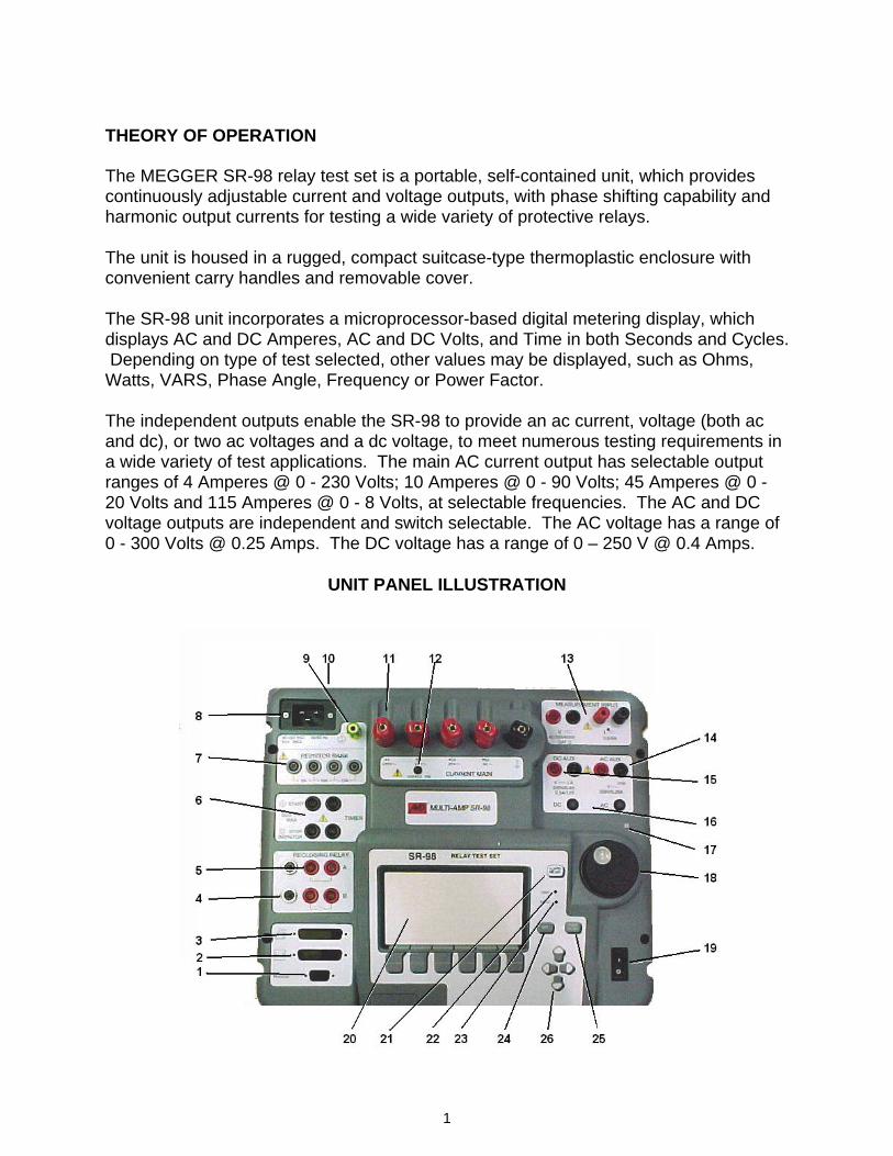
THEORY OF OPERATION The MEGGER SR-98 relay test set is a portable, self-contained unit, which provides continuously adjustable current and voltage outputs, with phase shifting capability and harmonic output currents for testing a wide variety of protective relays. The unit is housed in a rugged, compact suitcase-type thermoplastic enclosure with convenient carry handles and removable cover. The SR-98 unit incorporates a microprocessor-based digital metering display, which displays AC and DC Amperes, AC and DC Volts, and Time in both Seconds and Cycles. Depending on type of test selected, other values may be displayed, such as Ohms, Watts, VARS, Phase Angle, Frequency or Power Factor. The independent outputs enable the SR-98 to provide an ac current, voltage (both ac and dc), or two ac voltages and a dc voltage, to meet numerous testing requirements in a wide variety of test applications. The main AC current output has selectable output ranges of 4 Amperes @ 0 - 230 Volts; 10 Amperes @ 0 - 90 Volts; 45 Amperes @ 0 - 20 Volts and 115 Amperes @ 0 - 8 Volts, at selectable frequencies. The AC and DC voltage outputs are independent and switch selectable. The AC voltage has a range of 0 - 300 Volts @ 0.25 Amps. The DC voltage has a range of 0 – 250 V @ 0.4 Amps.
UNIT PANEL ILLUSTRATION
2
DESCRIPTION OF CONTROLS AND INSTRUMENTATION RS232 Serial Port (1): This 9-pin connector can be directly interfaced to a computer terminal, a serial data acquisition system, or a COM port on any personal computer. Required for use of MEGGER Software. See RS232 Serial Data Port for more information on the use of the port.
Interface Terminal (2): This interface terminal provides a 10 to 30 Volts AC output to a voltage coil of a phase angle meter. It should be noted that the voltage output is in-phase with the SR-98 main AC current output. DO NOT apply this voltage output to the current coil of a Phase Angle Meter. Optional interface cables are available to interface with MEGGER phase shifters models EPS and PVS-1000, see Optional Accessories in Specifications. This interface port may also used to connect two SR-98’s together for testing the slope characteristics of current differential relays, and to do harmonic restraint tests on transformer differential relays. When interconnected, there will not be more than a ± 3º phase shift between the two main current outputs (same output taps). An optional interface cable is available to interface two SR-98 units together, see Optional Accessories in Specifications.
Parallel Printer Port (3): The parallel printer port can be connected to any dot matrix, Centronix compatible printer. Used in conjunction with the PRINT SCRN button, it allows the user to print metered values / Test Results from the test screen directly to a printer. See Parallel Printer Port Section for more information about the port. RECLOSING RELAY Reset Fuses 1A (4): Protects the reclosing relay A/B contacts of the test set. If this fuse is tripped, the unit A/B contacts will not operate. If Fuse trips, check test circuit for cause of inappropriate current. Reset fuse by pressing down on fuse reset button. RECLOSING RELAY A and B Terminals (5): These two sets of relay contacts, one Normally Closed (A) and one Normally Open (B), work in conjunction with the Reclosing Relay Test Screen to simulate the opening and closing of circuit breakers.
3
TIMER START/STOP MONITOR Terminals (6): Two identical, independent, terminals are provided to monitor operation of relay contacts or trip SCR’s. See TIMER SETUP SCREEN for detailed descriptions of available modes of operation. RESISTOR BANK, 2A, 10A, 15A Terminals (7): Three terminals are provided. Output current from the SR-98 may be series through the resistor elements. Labeling shows maximum current for which the resistors are rated. See SELECTION OF OUTPUT TERMINALS, CURRENT MAIN for use and ratings.
Input Power Connection (8): The input connector is a standard IEC connector. See Input Power for description of power input and power cord selection. Protective Ground (Earthing) Terminal (9): Use this terminal to connect the chassis ground to earth ground. INPUT FUSES (F1, F2) (10): Input fuses are located on the backside of the top cover next to the input power connector. They protect the input power portion of the test set. If this fuse is blown, the unit will not operate. Fuse should be replaced with appropriate size, slow-blow, T rated fuses (see accessory list).
CURRENT MAIN Output Binding Posts (11): In conjunction with the common tap, four current rated output binding posts are provided to supply a variety of currents at various voltage levels. The output is controlled by the Control Knob (18). See Selection of Output Terminals for further description. WARNING: Do not use more than one current-rated tap at a time and only in conjunction with the common tap, never with each other. Some of the output terminals present a shock hazard, the user should take appropriate safety measures when the output is on. Never handle the test leads when the output is on. OUTPUT ON Lamp (12): Lights up whenever the AC current output terminals, CURRENT MAIN, are energized.
4
MEASUREMENT INPUT Terminals (13): Two sets of terminals are provided. The V, voltage terminals, is used to measure external AC or DC voltages up to a maximum of 600 Volts. The I, current terminals, is used to measure external AC or DC currents up to a maximum of 6 amperes. Caution: Use properly rated CATII insulated test leads with the MEASUREMENT INPUT and AC or DC AUX voltage output terminals, part number 684000 and 684001 (see accessory list). AC AUX Voltage Output Terminals (14): These output terminals are used to provide AC voltage to the device under test. The output is controlled by the Control Knob (18). 0 - 300 VAC MAX: Up to 300 Volts AC is available from these terminals.
Warning: Lethal voltages present when outputs are on
DC AUX Output Terminals (15): These output terminals are used to provide DC voltage or DC current to the device under test. The output is controlled by the Control Knob (18). 0 - 250 VDC MAX : Up to 250 Volts DC is available from these terminals. 0 – 2.5 ADC MAX : Up to 2.5 Amperes DC is available from these terminals. Note: DC voltage is available from all Relay Test Screens. The selection of either voltage or current is made from the DC Relay Test Screen. AC and DC Voltage Switches (16): The AC or DC Voltage Switches control the AC AUX and DC AUX voltage outputs, on and off. When either AC or DC voltage outputs are on, the lamp in the switch will be lit. While in the ON position, the outputs stay on regardless of the state of the INIT Switch (24). When testing Voltage Relays, the AC Voltage is dynamically changed from the NORMAL to the FAULT Voltage when the INIT Switch is pressed. When the relay operates the AC voltage output is turned off (see Voltage Relay Test Procedure).
5
Hardware Reset Button (17): This small recessed button is used to reset the hardware. In case of a total system shutdown, this button may be pressed to reset the hardware without switching the power on/off switch. Rotary Control Knob (18): The rotary knob rotates clockwise and counterclockwise to affect the highlighted field on the display screen. It provides continuous, variable, control of the selected output. Used to control the amplitudes of the CURRENT MAIN, AC AUX and DC AUX outputs. It may also be used to vary the Phase Angle between the AC AUX and CURRENT MAIN outputs. It may also be used in conjunction with the Cursor Arrow Keys to change default settings to the Timer and other control functions. For example, using the cursor arrows, a function like Ramp may be highlighted. Rotating the knob either direction changes the selected ramp rate from Normal to Fast to Slow back to Normal. POWER ON/OFF Switch (19): The switch controls the input power to the unit. Power on is indicated by the meter display, which will light up when the unit is energized. Digital Display (20): The digital display is a LCD panel with a resolution of 128 X 256 pixels. It indicates metered quantities of ac and dc current, ac and dc voltages, and Time in both Seconds and Cycles. Depending on type of test selected, other values may be displayed, such as Ohms, Watts, VARS, Phase Angle, Frequency or Power Factor. The metered readings are auto-ranging. In addition, the display also allows the user to select other features using the Function Buttons located directly below the display. See Display Screens for description of available functions.
ALARM RESET Button (21): In the event of a thermal overload, output overload, or a Power Factor Corrector (PFC) overload, the test set will protect itself and shut down operation. An overload message will be displayed on the screen indicating what caused the alarm. See ALARM DESCRIPTIONS under SERVICE DATA for more information. To reset , press this button. This is also referred to as a software reset. TRIP light (22): Works in conjunction with the STOP/MONITOR Terminals. The TRIP lamp will glow, when the condition set with the TIMER SETUP, STOP/MONITOR Mode is met.
6
SYNC light (23): When unit is synchronized to the power line source, this lamp will be lit. The line synchronization is selected from the Timer Setup Screen, see Out Freq. description.
INIT (INITIATE) Button (24): The INIT Button serves to initiate (turn on) the CURRENT MAIN output of the test set. In addition, it also serves to initiate certain test functions like a timing test on voltage relay.
PRINT SCRN Button (25): This button is used in conjunction with the Parallel Printer Port to print the metered / test values from the display screen. Up, Down, Right and Left Arrows (26): These arrows move the graphic screen highlighted function up, down, right and left on the screen. It works in conjunction with the rotary knob to change the highlighted function.
INPUT POWER There are two versions of the SR-98. One is rated for 230 volt operation only. The other has a universal input of 90 to 253 volts, 1700 VA max. Model SR-98-1/60 comes with a universal power input (90 - 253 VAC, 50/60 Hz input), a north American power cord and firmware set to default to 60 Hz output on power up. Model SR-98-2/50 comes with a universal power input (90 - 253 VAC, 50/60 Hz input), a international color coded power cord and firmware set to default to 50 Hz output on power up. Model SR-98-3/50 has a power input of 230 volt only (230 VAC, 50/60 Hz input), a Continental Europe power cord and firmware set to default to 50 Hz output on power up.
7
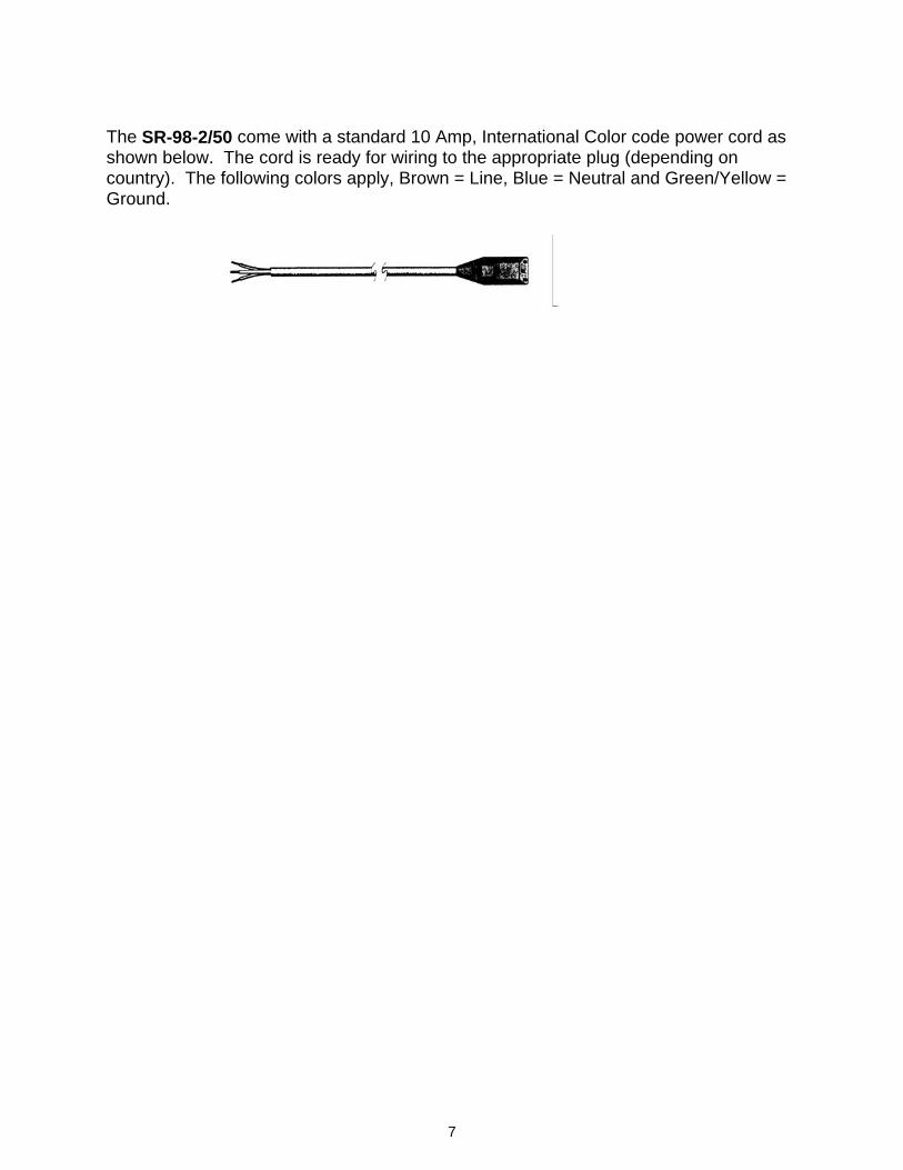
The SR-98-2/50 come with a standard 10 Amp, International Color code power cord as shown below. The cord is ready for wiring to the appropriate plug (depending on country). The following colors apply, Brown = Line, Blue = Neutral and Green/Yellow = Ground.
8
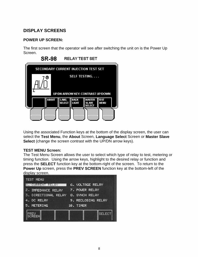
DISPLAY SCREENS POWER UP SCREEN: The first screen that the operator will see after switching the unit on is the Power Up Screen.
Using the associated Function keys at the bottom of the display screen, the user can select the Test Menu, the About Screen, Language Select Screen or Master Slave Select (change the screen contrast with the UP/DN arrow keys). TEST MENU Screen: The Test Menu Screen allows the user to select which type of relay to test, metering or timing function. Using the arrow keys, highlight to the desired relay or function and press the SELECT function key at the bottom-right of the screen. To return to the Power Up screen, press the PREV SCREEN function key at the bottom-left of the display screen.
9
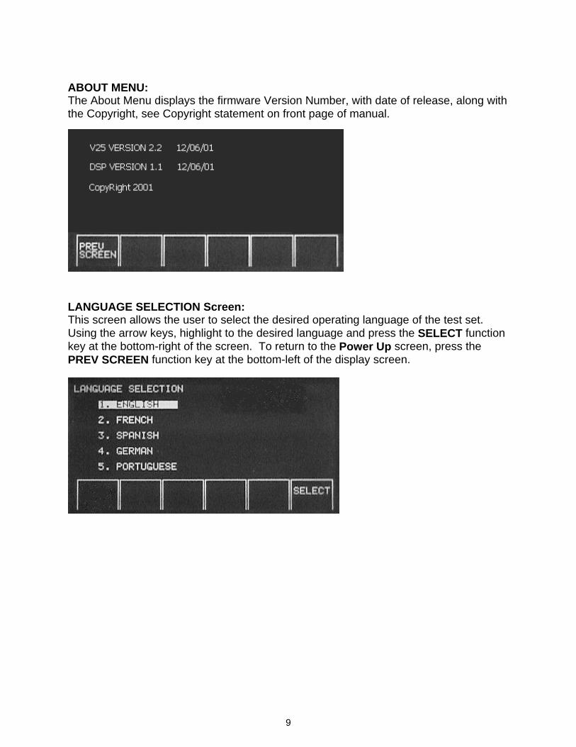
ABOUT MENU: The About Menu displays the firmware Version Number, with date of release, along with the Copyright, see Copyright statement on front page of manual.
LANGUAGE SELECTION Screen: This screen allows the user to select the desired operating language of the test set. Using the arrow keys, highlight to the desired language and press the SELECT function key at the bottom-right of the screen. To return to the Power Up screen, press the PREV SCREEN function key at the bottom-left of the display screen.
10
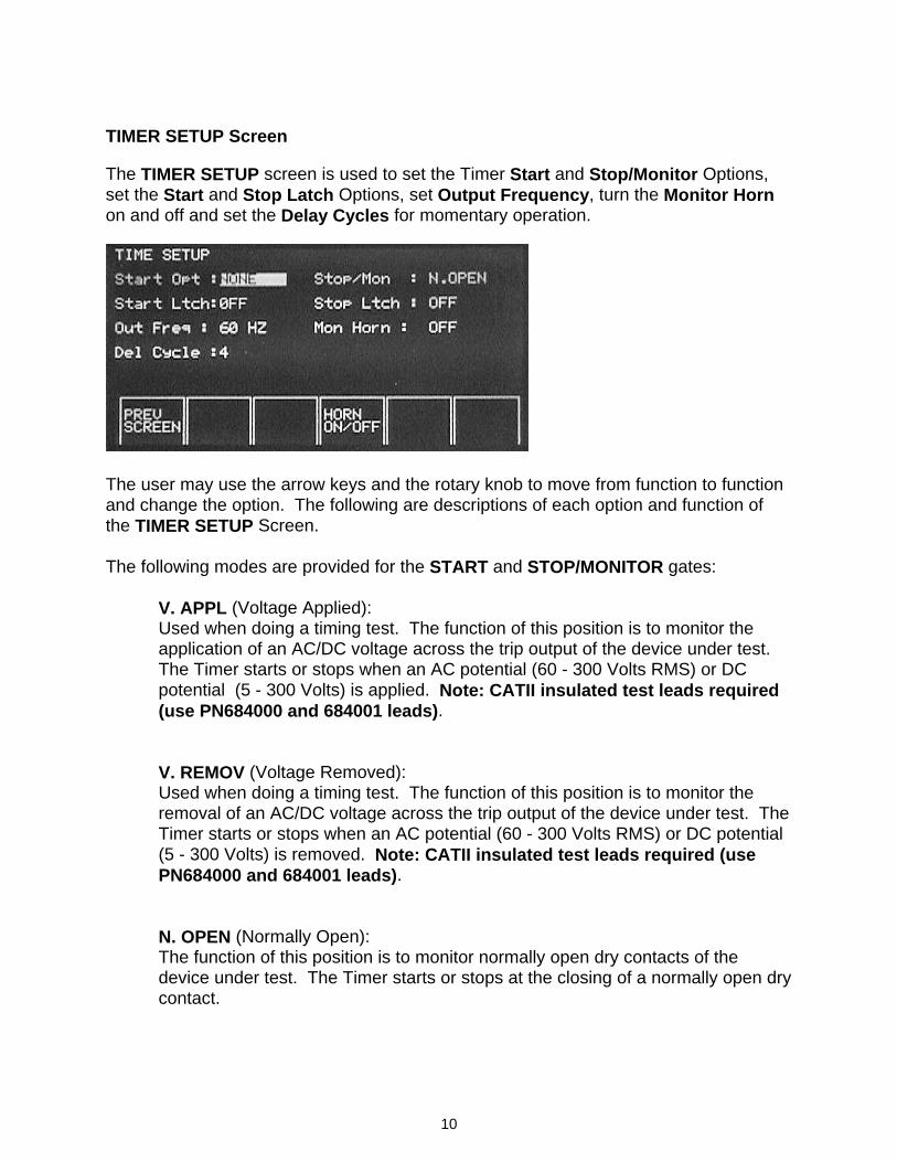
TIMER SETUP Screen The TIMER SETUP screen is used to set the Timer Start and Stop/Monitor Options, set the Start and Stop Latch Options, set Output Frequency, turn the Monitor Horn on and off and set the Delay Cycles for momentary operation.
The user may use the arrow keys and the rotary knob to move from function to function and change the option. The following are descriptions of each option and function of the TIMER SETUP Screen. The following modes are provided for the START and STOP/MONITOR gates: V. APPL (Voltage Applied):
Used when doing a timing test. The function of this position is to monitor the application of an AC/DC voltage across the trip output of the device under test. The Timer starts or stops when an AC potential (60 - 300 Volts RMS) or DC potential (5 - 300 Volts) is applied. Note: CATII insulated test leads required (use PN684000 and 684001 leads).
V. REMOV (Voltage Removed): Used when doing a timing test. The function of this position is to monitor the
removal of an AC/DC voltage across the trip output of the device under test. The Timer starts or stops when an AC potential (60 - 300 Volts RMS) or DC potential (5 - 300 Volts) is removed. Note: CATII insulated test leads required (use PN684000 and 684001 leads).
N. OPEN (Normally Open): The function of this position is to monitor normally open dry contacts of the
device under test. The Timer starts or stops at the closing of a normally open dry contact.
11
N.CLOSE (Normally Closed): The function of this position is to monitor normally closed dry contacts of the
device under test. The Timer starts or stops at the opening of a normally closed dry contact.
INIT (Initiate): When the TIMER START Mode is in this position, the Timer will start when the
output, or test, is initiated using the INIT Button. DE-INIT (De-initiate): When the contacts close on the timer start terminals, the output current is de-
initiated and the timer is started. The trip contacts are monitored by the start terminals and the contacts associated with the back-stop are monitored with the stop terminals, see Overcurrent Relay, Run-back Test for more details.
CURR X (Current Actuate): This option is associated with the Stop/Mon function. The Timer stops when the
device under test interrupts the CURRENT MAIN output. The CURR X position is used when the device under test has no contacts other than those used to pass current (such as a single-pole circuit breaker).
NOTE: Output must be maintained above threshold level or timer error will result. MON (C) (Monitor Continuity): The function of this position is to monitor the change of state of normally open or
closed dry contacts of the device under test. The TRIP lamp will light at the closing of a normally open dry contact. If the Horn is turned on, then the horn will sound when the contacts close.
MON (V) (Monitor Voltage): The function of this position is to monitor the change of state of an AC/DC
voltage output from the device under test. The TRIP lamp will light at the applying of a AC potential (60 - 300 Volts RMS) or DC potential (5 - 300 Volts) voltage. If the Horn is turned on, then the horn will sound when the voltage is applied. Note: CATII insulated test leads required (use PN684000 and 684001 leads).
LATCH ON/OFF: This mode is used in conjunction with the selected START/STOP options and the START/STOP Terminals to supervise the starting and stopping of the Timer. START LATCH: The Timer START LATCH ON allows timing to be initiated by a Start Gate and to
be stopped only by the selected Stop Gate. When unlatched, LATCH OFF, allows timing to be stopped when the Start Gate is reversed (such as when timing the closing and opening of a single contact as in measuring the trip-free operating time of a circuit breaker).
12
STOP LATCH: When the STOP circuit is latched ON, the stop latch allows timing to be stopped
at the first operation of any selected stop gate. When the STOP circuit is latched OFF, the stop latch allows timing to be stopped by any stop gate and then restarted if the stop gate reverses (provided a start gate is still energized) and stopped when the stop gate is again true. NOTE: When using the MONITOR feature, the STOP LATCH must be OFF.
Out Freq.: Based on the Model number of the unit, this value will default to either 60 HZ or 50 HZ. If another output frequency is desired (other than the default) for the CURRENT MAIN output, the user highlights this value and rotates the Control Knob either clockwise to increase or counter-clockwise to decrease the value. Output frequencies available are 16.66, 25, 33.3, 50, 60, 100, 120, 125, 150, 180, 250 or 300 Hz. In addition, to synchronize the CURRENT MAIN to the input line source, select 60 Hz SYNC or 50 Hz SYNC. Once selected the SYNC light on the front panel will be lit. The output current will be in-phase with the line voltage, ± 5 degrees, depending on which output tap is selected and the test current set. Note: The higher output taps results in less phase error. Mon Horn: The user can select to turn the Monitor Horn ON or OFF. The horn sounds when the relay contacts close. In the event that the contacts are normally closed, the horn would sound continuously, until they are opened. The default setting is Horn OFF. To change, press HORN ON/OFF button to turn ON. Del Cycles: Used in conjunction with the INIT button and the MODE SELECT button, the user can select the number of cycles that the CURRENT MAIN output will be on. The MODE SELECT button at the bottom of each Test Screen controls whether the output is in the MOM. (MOMENTARY) mode, or the MAINT. (MAINTAIN Mode). If in the MOM. mode, the output will only be on for the Del. Cycles setting. For example, the default is 4 cycles. This means that the output will be ON for approximately 4 cycles. This value may be changed up to 10 cycles by using the arrow keys to highlight the value and rotating the control knob to the desired number of delay cycles. DESCRIPTION OF TEST SCREENS The following descriptions apply to the different Test Screens that appear in the TEST MENU Screen. There are common Amplitudes, Features and Function Buttons associated with many of the screens. These Amplitudes, Features and Function Buttons will be described only one time, with the CURRENT RELAY Test Screen. Other Values, Features or Function Buttons that are unique to an individual Test Screen will be described with the associated screen description.
13
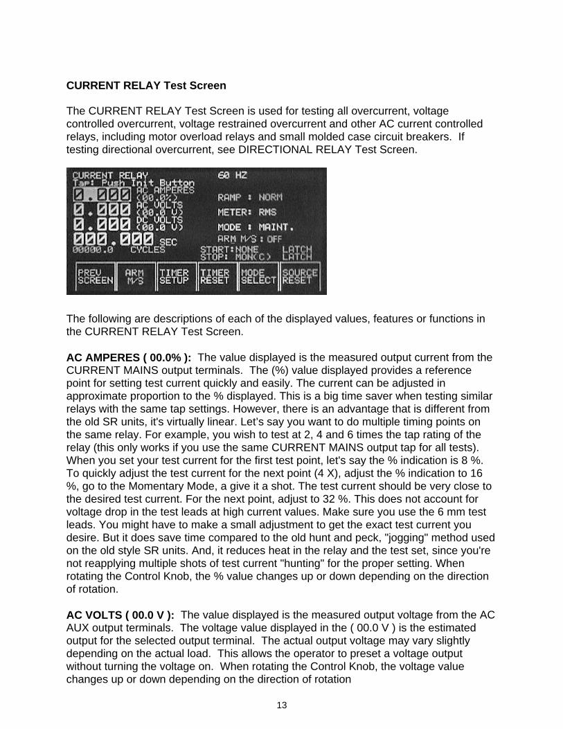
CURRENT RELAY Test Screen The CURRENT RELAY Test Screen is used for testing all overcurrent, voltage controlled overcurrent, voltage restrained overcurrent and other AC current controlled relays, including motor overload relays and small molded case circuit breakers. If testing directional overcurrent, see DIRECTIONAL RELAY Test Screen.
The following are descriptions of each of the displayed values, features or functions in the CURRENT RELAY Test Screen. AC AMPERES ( 00.0% ): The value displayed is the measured output current from the CURRENT MAINS output terminals. The (%) value displayed provides a reference point for setting test current quickly and easily. The current can be adjusted in approximate proportion to the % displayed. This is a big time saver when testing similar relays with the same tap settings. However, there is an advantage that is different from the old SR units, it's virtually linear. Let’s say you want to do multiple timing points on the same relay. For example, you wish to test at 2, 4 and 6 times the tap rating of the relay (this only works if you use the same CURRENT MAINS output tap for all tests). When you set your test current for the first test point, let's say the % indication is 8 %. To quickly adjust the test current for the next point (4 X), adjust the % indication to 16 %, go to the Momentary Mode, a give it a shot. The test current should be very close to the desired test current. For the next point, adjust to 32 %. This does not account for voltage drop in the test leads at high current values. Make sure you use the 6 mm test leads. You might have to make a small adjustment to get the exact test current you desire. But it does save time compared to the old hunt and peck, "jogging" method used on the old style SR units. And, it reduces heat in the relay and the test set, since you're not reapplying multiple shots of test current "hunting" for the proper setting. When rotating the Control Knob, the % value changes up or down depending on the direction of rotation. AC VOLTS ( 00.0 V ): The value displayed is the measured output voltage from the AC AUX output terminals. The voltage value displayed in the ( 00.0 V ) is the estimated output for the selected output terminal. The actual output voltage may vary slightly depending on the actual load. This allows the operator to preset a voltage output without turning the voltage on. When rotating the Control Knob, the voltage value changes up or down depending on the direction of rotation
14
DC VOLTS ( 00.0 V ): The value displayed is the measured output voltage from the DC AUX output terminals. The voltage value displayed in the ( 00.0 V ) is the estimated output for the selected output terminal. The actual output voltage may vary slightly depending on the actual load. This allows the operator to preset a voltage output without turning the voltage on. When rotating the Control Knob, the voltage value changes up or down depending on the direction of rotation. SEC / CYCLES: The time displayed in the SEC (seconds) display area is the operating time of the device under test in seconds. The value displayed in the CYCLES display area is the operating time in cycles based normally on either a 60 Hz or 50 Hz time base. The time base depends on the base frequency set in the Timer Setup Screen (see Timer Setup Screen for details on Frequency changes). 60 or 50 Hz: The frequency displayed in the upper right corner of the display screen indicates the output frequency of the CURRENT MAIN and AC AUX output (see OUT FREQ. Under Timer Setup Screen). It also indicates what the base frequency is for timing in Cycles (see SEC/CYCLES above). Ramp: There are three speeds at which the output can change when rotating the Control Knob. They are, Normal, Slow and Fast. To change the Ramp speed, use the cursor arrows to highlight the Ramp window. Rotating the knob either direction changes the selected ramp rate from Normal to Fast to Slow back to Normal. Once selected, use the arrow keys to cursor back to the amplitude value that you want to change and rotate the Control Knob. Meter: There are two selections for metered values. They are RMS (Root Mean Squared) or PEAK. The highlighted, metered value displayed can be either of these two selections. Normally, RMS is required, therefore the defaulted value displayed is RMS. To change, use the cursor arrows and control knob similar to that described above for Ramp. Mode: There are three selections for the mode of operation. They are MOM (momentary), MAINT (maintain) and CA (current actuate). In the MOM mode the CURRENT MAIN is turned on momentarily for the Delay Cycles time period, which is defaulted to 4 cycles (see Timer Setup Screen for description of Delay Cycles). This feature can be changed from MOM to MAINT by pressing the MODE SELECT function button at the bottom of the screen, see MODE SELECT for description of operation. START: NONE LATCH STOP: MON(C) LATCH : Indicators of the Timer START and STOP gate settings (see Timer Setup Screen for details of settings). These indicators aid the operator in knowing what the setup is for the Timer without needing to go to the Timer Setup Screen. To change the settings, press the TIMER SETUP function button at the bottom of the screen.
15
PREV SCREEN: This function button returns the operator to the previous display screen, which would be the TEST MENU Screen. ARM M/S: This function button arms the initiate circuit for initiation of the output current when operating two SR-98’s in the Master / Slave mode. When pressed, the CURRENT MAIN outputs will initiate simultaneously when the Master SR-98 INIT button is pressed. Note: Both the Master and Slave ARM M/S buttons must be pressed prior to pressing the Master INIT button. See SELECTION OF MASTER UNIT for more details. TIMER SETUP: This function button selects the TIMER SETUP Screen. The TIMER SETUP Screen was described earlier. TIMER RESET: This function button allows the operator to reset the Timer prior to doing a timing test. MODE SELECT: This function button allows the operator to select MOM (Momentary), MAINT (Maintained) or CA (Current Actuate) operation of the CURRENT MAIN output. The MOM mode is used to set test currents quickly and reduces heating of the device under test. The MAINT mode is normally used when turning on outputs for an indefinite period of time (such as timing tests). The CA mode is used when timing instantaneous only, small, single-pole molded case circuit breakers. When in the CA mode the sampling rate is changed in order to capture very short operating times of single pole breakers. Since single pole breakers do not have contacts to monitor, the SR-98 monitors the current through the breaker under test. When the current is interrupted by the breaker operation, the SR-98 captures the short operating time and displays it. This feature is only used when testing instantaneous, single-pole, molded case circuit breakers. For timing tests of short and long time delay molded case circuit breakers, the MAINT mode is used.
16
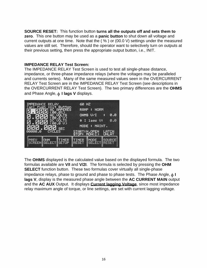
SOURCE RESET: This function button turns all the outputs off and sets them to zero. This one button may be used as a panic button to shut down all voltage and current outputs at one time. Note that the ( % ) or (00.0 V) settings under the measured values are still set. Therefore, should the operator want to selectively turn on outputs at their previous setting, then press the appropriate output button, i.e., INIT. IMPEDANCE RELAY Test Screen: The IMPEDANCE RELAY Test Screen is used to test all single-phase distance, impedance, or three-phase impedance relays (where the voltages may be paralleled and currents series). Many of the same measured values seen in the OVERCURRENT RELAY Test Screen are in the IMPEDANCE RELAY Test Screen (see descriptions in the OVERCURRENT RELAY Test Screen). The two primary differences are the OHMS and Phase Angle, φ I lags V displays.
The OHMS displayed is the calculated value based on the displayed formula. The two formulas available are V/I and V/2I. The formula is selected by pressing the OHM SELECT function button. These two formulas cover virtually all single-phase impedance relays, phase to ground and phase to phase tests. The Phase Angle, φ I lags V, display is the measured phase angle between the AC CURRENT MAIN output and the AC AUX Output. It displays Current lagging Voltage, since most impedance relay maximum angle of torque, or line settings, are set with current lagging voltage.
17
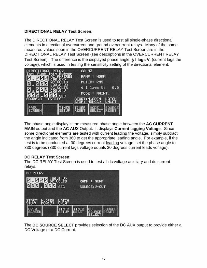
DIRECTIONAL RELAY Test Screen: The DIRECTIONAL RELAY Test Screen is used to test all single-phase directional elements in directional overcurrent and ground overcurrent relays. Many of the same measured values seen in the OVERCURRENT RELAY Test Screen are in the DIRECTIONAL RELAY Test Screen (see descriptions in the OVERCURRENT RELAY Test Screen). The difference is the displayed phase angle, φ I lags V, (current lags the voltage), which is used in testing the sensitivity setting of the directional element.
The phase angle display is the measured phase angle between the AC CURRENT MAIN output and the AC AUX Output. It displays Current lagging Voltage. Since some directional elements are tested with current leading the voltage, simply subtract the angle indicated from 360 to get the appropriate leading angle. For example, if the test is to be conducted at 30 degrees current leading voltage, set the phase angle to 330 degrees (330 current lags voltage equals 30 degrees current leads voltage). DC RELAY Test Screen: The DC RELAY Test Screen is used to test all dc voltage auxiliary and dc current relays.
The DC SOURCE SELECT provides selection of the DC AUX output to provide either a DC Voltage or a DC Current.
18
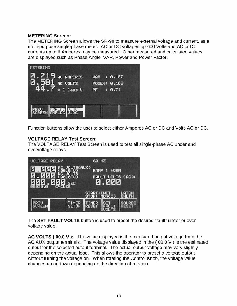
METERING Screen: The METERING Screen allows the SR-98 to measure external voltage and current, as a multi-purpose single-phase meter. AC or DC voltages up 600 Volts and AC or DC currents up to 6 Amperes may be measured. Other measured and calculated values are displayed such as Phase Angle, VAR, Power and Power Factor.
Function buttons allow the user to select either Amperes AC or DC and Volts AC or DC. VOLTAGE RELAY Test Screen: The VOLTAGE RELAY Test Screen is used to test all single-phase AC under and overvoltage relays.
The SET FAULT VOLTS button is used to preset the desired “fault” under or over voltage value. AC VOLTS ( 00.0 V ): The value displayed is the measured output voltage from the AC AUX output terminals. The voltage value displayed in the ( 00.0 V ) is the estimated output for the selected output terminal. The actual output voltage may vary slightly depending on the actual load. This allows the operator to preset a voltage output without turning the voltage on. When rotating the Control Knob, the voltage value changes up or down depending on the direction of rotation.
19
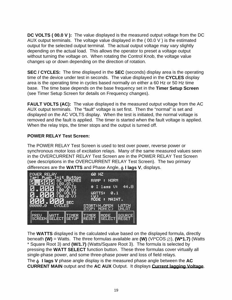
DC VOLTS ( 00.0 V ): The value displayed is the measured output voltage from the DC AUX output terminals. The voltage value displayed in the ( 00.0 V ) is the estimated output for the selected output terminal. The actual output voltage may vary slightly depending on the actual load. This allows the operator to preset a voltage output without turning the voltage on. When rotating the Control Knob, the voltage value changes up or down depending on the direction of rotation. SEC / CYCLES: The time displayed in the SEC (seconds) display area is the operating time of the device under test in seconds. The value displayed in the CYCLES display area is the operating time in cycles based normally on either a 60 Hz or 50 Hz time base. The time base depends on the base frequency set in the Timer Setup Screen (see Timer Setup Screen for details on Frequency changes). FAULT VOLTS (AC): The value displayed is the measured output voltage from the AC AUX output terminals. The “fault” voltage is set first. Then the “normal” is set and displayed on the AC VOLTS display. When the test is initiated, the normal voltage is removed and the fault is applied. The timer is started when the fault voltage is applied. When the relay trips, the timer stops and the output is turned off. POWER RELAY Test Screen: The POWER RELAY Test Screen is used to test over power, reverse power or synchronous motor loss of excitation relays. Many of the same measured values seen in the OVERCURRENT RELAY Test Screen are in the POWER RELAY Test Screen (see descriptions in the OVERCURRENT RELAY Test Screen). The two primary differences are the WATTS and Phase Angle, φ I lags V, displays.
The WATTS displayed is the calculated value based on the displayed formula, directly beneath (W) = Watts. The three formulas available are (W) (VI*COS ∅), (W*1.7) (Watts * Square Root 3) and (W/1.7) (Watts/Square Root 3). The formula is selected by pressing the WATT SELECT function button. These three formulas cover virtually all single-phase power, and some three-phase power and loss of field relays. The φ I lags V phase angle display is the measured phase angle between the AC CURRENT MAIN output and the AC AUX Output. It displays Current lagging Voltage.
20
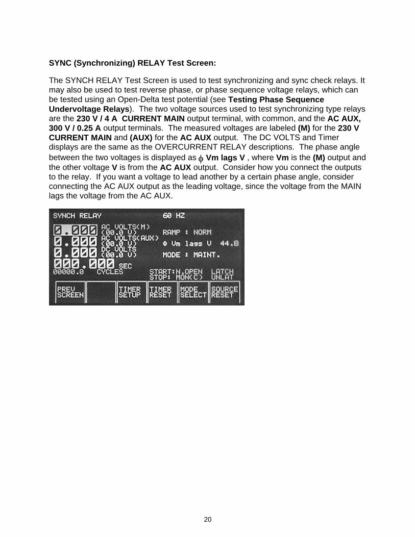
SYNC (Synchronizing) RELAY Test Screen: The SYNCH RELAY Test Screen is used to test synchronizing and sync check relays. It may also be used to test reverse phase, or phase sequence voltage relays, which can be tested using an Open-Delta test potential (see Testing Phase Sequence Undervoltage Relays). The two voltage sources used to test synchronizing type relays are the 230 V / 4 A CURRENT MAIN output terminal, with common, and the AC AUX, 300 V / 0.25 A output terminals. The measured voltages are labeled (M) for the 230 V CURRENT MAIN and (AUX) for the AC AUX output. The DC VOLTS and Timer displays are the same as the OVERCURRENT RELAY descriptions. The phase angle between the two voltages is displayed as φ Vm lags V , where Vm is the (M) output and the other voltage V is from the AC AUX output. Consider how you connect the outputs to the relay. If you want a voltage to lead another by a certain phase angle, consider connecting the AC AUX output as the leading voltage, since the voltage from the MAIN lags the voltage from the AC AUX.
21
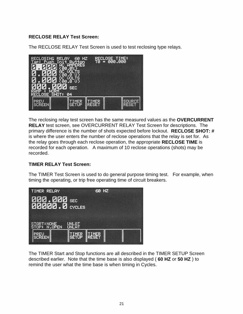
RECLOSE RELAY Test Screen: The RECLOSE RELAY Test Screen is used to test reclosing type relays.
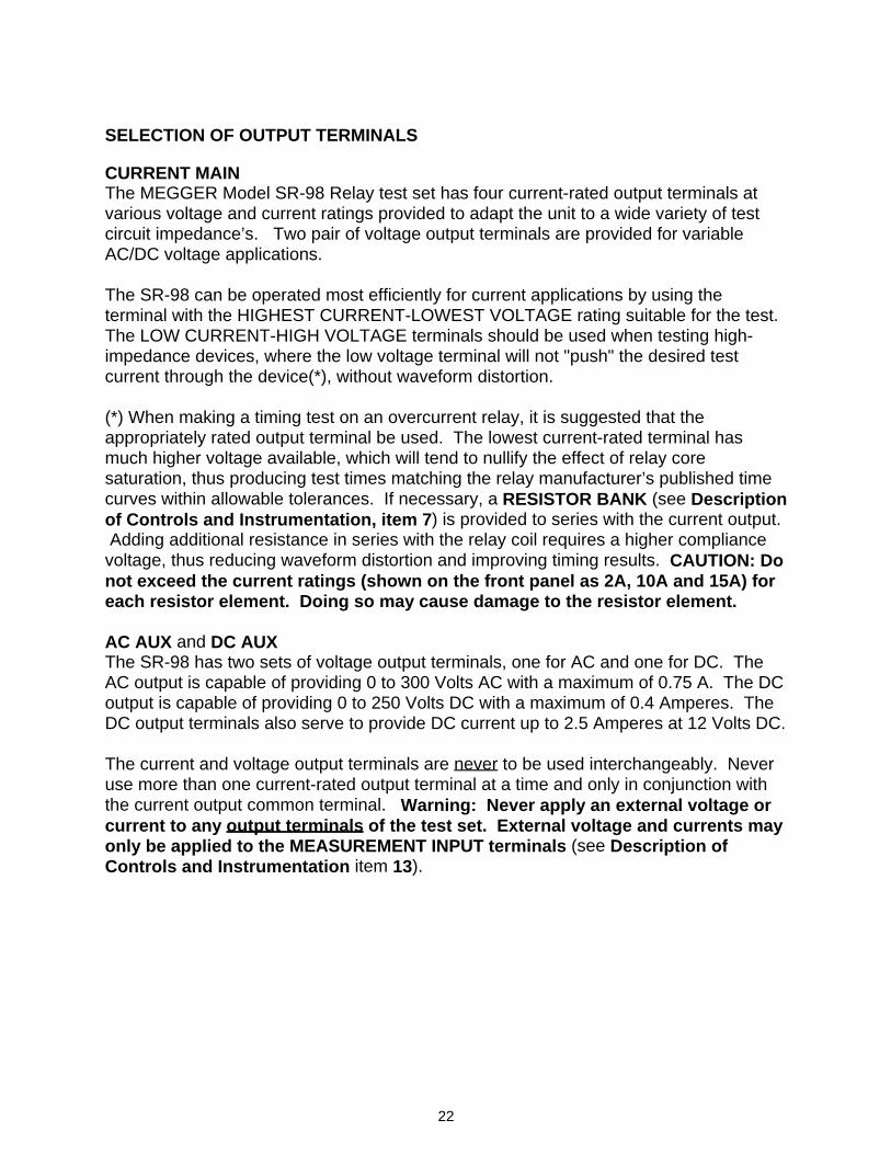
The reclosing relay test screen has the same measured values as the OVERCURRENT RELAY test screen, see OVERCURRENT RELAY Test Screen for descriptions. The primary difference is the number of shots expected before lockout. RECLOSE SHOT: # is where the user enters the number of reclose operations that the relay is set for. As the relay goes through each reclose operation, the appropriate RECLOSE TIME is recorded for each operation. A maximum of 10 reclose operations (shots) may be recorded. TIMER RELAY Test Screen: The TIMER Test Screen is used to do general purpose timing test. For example, when timing the operating, or trip free operating time of circuit breakers.
The TIMER Start and Stop functions are all described in the TIMER SETUP Screen described earlier. Note that the time base is also displayed ( 60 HZ or 50 HZ ) to remind the user what the time base is when timing in Cycles.
22
SELECTION OF OUTPUT TERMINALS CURRENT MAIN The MEGGER Model SR-98 Relay test set has four current-rated output terminals at various voltage and current ratings provided to adapt the unit to a wide variety of test circuit impedance’s. Two pair of voltage output terminals are provided for variable AC/DC voltage applications. The SR-98 can be operated most efficiently for current applications by using the terminal with the HIGHEST CURRENT-LOWEST VOLTAGE rating suitable for the test. The LOW CURRENT-HIGH VOLTAGE terminals should be used when testing high-impedance devices, where the low voltage terminal will not "push" the desired test current through the device(*), without waveform distortion. (*) When making a timing test on an overcurrent relay, it is suggested that the appropriately rated output terminal be used. The lowest current-rated terminal has much higher voltage available, which will tend to nullify the effect of relay core saturation, thus producing test times matching the relay manufacturer’s published time curves within allowable tolerances. If necessary, a RESISTOR BANK (see Description of Controls and Instrumentation, item 7) is provided to series with the current output. Adding additional resistance in series with the relay coil requires a higher compliance voltage, thus reducing waveform distortion and improving timing results. CAUTION: Do not exceed the current ratings (shown on the front panel as 2A, 10A and 15A) for each resistor element. Doing so may cause damage to the resistor element. AC AUX and DC AUX The SR-98 has two sets of voltage output terminals, one for AC and one for DC. The AC output is capable of providing 0 to 300 Volts AC with a maximum of 0.75 A. The DC output is capable of providing 0 to 250 Volts DC with a maximum of 0.4 Amperes. The DC output terminals also serve to provide DC current up to 2.5 Amperes at 12 Volts DC. The current and voltage output terminals are never to be used interchangeably. Never use more than one current-rated output terminal at a time and only in conjunction with the current output common terminal. Warning: Never apply an external voltage or current to any output terminals of the test set. External voltage and currents may only be applied to the MEASUREMENT INPUT terminals (see Description of Controls and Instrumentation item 13).
23
SELECTION OF MASTER UNIT Each Model SR-98 can be operated independently. However, when performing tests that require more than one SR-98, such as testing current differential relays, it is necessary to select one unit as a Master Unit. The Master Unit establishes the phase reference for both Master and Slave units. This allows the output currents to be virtually in-phase, when doing slope (differential characteristic) tests (requires the same rated output tap is used for both units). Additionally, the Master Unit controls the initiation of both AC CURRENT MAIN outputs. Since all Model SR-98 test sets are identical, any unit can be used as the Master Unit. Incorporated on the front panel of the SR-98 is an interface terminal port next to the following symbol,
To interconnect two SR-98 units together requires the optional interface cable, part number 51679. Simply plug the interface cable into the two interface terminals prior to turning the units on. From the POWER UP Screen, press the MASTER SLAVE SELECT button on both units. Then press the MODE SELECT button for the Slave Unit. Note that both displays changed. The Slave Unit states that it is Slave and the external unit is the Master, while the Master Unit states that it is Master and the external unit is the Slave. Press the PREV SCREEN button to return to the POWER UP Screen. Normally, the Master/Slave mode is used when test requirements call for two currents. The two currents are normally used to provide restraint and operating currents when testing current differential relays. Another application is when you want the currents to sum as when testing harmonic restraint elements. To test current differential relays, see TESTING CURRENT DIFFERENTIAL RELAYS for the step by step test procedure.
24
SERVICE DATA MAINTENANCE INSTRUCTIONS Maintenance intervals depend on usage, but a maximum of every six months is recommended.
WARNING: Do not service unit unless it is disconnected from its power source. 1. Enclosure: The enclosure can be cleaned with a soft cloth. If heavily soiled, the
cloth can be dampened with an approved solvent that does not attack the finish or leave residue.
2. Control Panel: The control panel can be wiped clean with a soft, dry cloth. Do
not wipe the meter lens with a cloth. If a breath of air will not remove dirt, brush it away lightly with a soft-bristle instrument brush.
3. Other Components: Check all knobs, printed circuit boards, screws, fasteners,
connections and terminals for tightness and proper position. Remove dust with a soft brush and breath of air. Output terminal connection tightness is particularly important. If they become loose, excessive heating of the terminals and poor current output will result.
4. Insulation: Check wiring and other insulated components for burning, cracking or
other damage.
IMPORTANT NOTES Do not use lubricants or solvents of any kind in the test set except as specifically recommended. If damage or malfunction is suspected or repairs deemed necessary, consult a MEGGER Representative for assistance if it is unclear what course of action is needed. Be sure to provide all name plate data when making inquiries. BASIC TROUBLESHOOTING The troubleshooting information relies on the technician to have a through understanding of the operation of the unit. If the technician is unfamiliar with the unit, he or she should not attempt to repair. The technician should contact the factory before attempting repairs. Provide the Megger part number for the part or assembly in question and the serial number of the SR-98 when making inquiries.
25
WARNING It may become necessary to energize the SR-98 to properly troubleshoot some of the outputs. The technician must take all applicable safety precautions for working on energized circuits. NOTESBefore suspecting a failure in the SR-98, review the Description of Controls and Instrumentation and Theory of Operation sections to ensure that the problem is not a result of operating error. Preliminary testing of the SR-98 within its specified limits can help determine if a malfunction actually exists, identify the type of malfunction and define the general area of the failure. In many cases, the SR-98 will identify what the problem is and display an alarm description on the display screen, see Alarm Descriptions. Common causes of malfunctions, other than improper operation are, incorrect power input (voltage above or below specified limits), incorrect test signal voltages applied to the Timer Monitor/Start/Stop gates (outside of the specified AC/DC Applied/Removed limits), and contact or circuit resistance too great for the Dry Contact gates to operate properly on the Monitor/Stop gate. Other common causes are blown or tripped fuse(s), cracked, broken or corroded wiring connections. Power Input Input voltage affects the whole unit and may or may not cause permanent damage if voltage is incorrect. These problems can often be corrected by simply using a better source of input power. See rated voltage on front panel of unit. Some symptoms are as follows: 1. Low voltage: Erratic operation, no output, fuse operation. 2. High voltage: Fuse operation, power supply failure. Basic troubleshooting of the input power and front panel controls are as follows. 1. No power: Check power source and line cord. Check mains input fuse(s). Display blackout could be a power supply failure, or loose connection
between printed circuit boards. WARNING: If display is blacked out, but the output(s)-energized lamps are lit, the output(s) are energized. To check the power supply connections, remove the unit from the chassis (see ‘Removal of Chassis’ below).
2. Erratic output voltage or current: Individual output voltage or current not available.
26
a. See Alarm Descriptions. b. If no current through the Resistor Bank, check resistor using an
Ohmmeter. c. Check test leads for broken conductors.
3. Removal of Chassis from Enclosure: To remove the chassis, a. Disconnect the power cord from the unit. b. Carefully remove the four- (4) screws located on the front panel, two
on each side. c. Turn the unit on to back side, and slide the unit from the enclosure. Digital Display /Timer Section Basic troubleshooting is as follows: 1. No display when the SR-98 is energized: Power supply failure, defective display IC's, defective components on
printed circuit board, loose cable connection between power supply and printed circuit board. See “No Power” above for corrective action.
2. Weak or defective display: Contrast needs to be adjusted, see Power Up screen to adjust. Poor
supply voltage, defective display, or defective components on display board. See ‘No Power’ above for corrective action.
3. Timer will not Start or Stop counting. Check the Start/Stop modes for
proper selection. Check that the Timer Latches are properly set. If the Timer will not stop when using the CURR X (Current Actuate) mode, check to make sure the Timer Start Latch is OFF. If the Timer will not Start when Initiating the output, check to make sure the Timer Start is set to the INIT (Initiate) position.
4. Counting errors: AC applied or removed Start/Stop signals can create, what appears to be
poor repeatability, an inaccuracy or a malfunction in the Timer. The lower the voltage level, the more serious the "error" will be. What appears to be an error, however, is actually a variation in the point on the sine wave at which the voltage is great enough to cause the gate circuit to operate. If the circuit used for the timing test has a low AC voltage, and the point at which the contact in the test circuit opens or closes, is at or close to zero on the sine wave, the period of time before the voltage level will be high enough to trigger the gate circuit can be as much as 4 milliseconds. The total timing variation can be as much as 8 milliseconds. The shorter the duration of the timing test, the more significant the variation becomes. Therefore, if small timing variations would present a problem, it is recommended that an AC voltage of 115 volts or above or a DC voltage be used for voltage applied/removed test selections.
27
When the SR-98 Timer calibration is being tested, the AC voltage variable
is often overlooked. This is particularly true when the Timer is compared to a counter and the two are triggered simultaneously with an electronic switch. For best results, a DC voltage should be used to eliminate the variable. If testing the AC voltage Start/Stop characteristics is desired, then the Start/Stop signal must be triggered at the same point on the sine wave to assure that the gate signal will be repeatable. In addition, the specified rms AC voltage values for the various Start/Stop control selections must be adhered to.
If a timing error or variation persists after all the suspected causes of error
have been eliminated, then it is fairly certain the Timer is malfunctioning. Contact factory for return instructions.
ALARM DESCRIPTIONS The SR-98 microprocessor and digital signal processors have the capability to monitor and diagnose certain problems internally. Many of the circuits are protected against over load and over temperature. When one of these conditions exist, the test system protects itself and may shut down operation. Test system will display an alarm message to the operator explaining what condition caused the shut down. Below is a list of the alarm messages that may be displayed. PFC1 Over Current: PFC1 stands for Power Factor Corrector #1. This alarm indicates that there was a overcurrent condition on PFC1. This could indicate that there is an internal problem, which is drawing too much current. Another possible condition is that the output load(s) exceed the maximum output ratings, which caused the PFC module to shut down. PFC2 Over Current: PFC2 stands for Power Factor Corrector #2. See PFC1 above for description. PFC1 Fail: This alarm indicates that PFC1 has failed to power up, or was shut down by the operating system. If it failed to power up, this could indicate that there is an input voltage problem, or that the PFC module is not operating (internally). In the event of an over load on the Main Current output, the operating system will shutdown the PFC module to protect it, see MAIN Over Current for more details. PFC2 Fail: See PFC1 above for description. PFC1 Over Temp: This alarm indicates that there is an over temperature condition on PFC1. This could indicate that there is an internal problem, which is causing an over temperature condition (fan not working). Another possible condition is that the output(s) duty cycle has exceeded the maximum ratings, which caused the PFC module to shut down. In either case, allow the unit to cool down. Leave the unit on with the fan running, and wait about 15 to 20 minutes before trying to operate again.
28
PFC2 Over Temp: See PFC1 above for description. AUX Over Current: AUX stands for Auxiliary output. This alarm indicates that there was a overcurrent condition on the AC AUX output. This could indicate that there is an internal problem, which is drawing too much current. Another possible condition is that the output load exceeds the maximum output rating, which caused the AUX output to shut down. MAIN Over Current: MAIN stands for AC CURRENT MAIN output. This alarm indicates that there was an over current condition on the CURRENT MAIN output. This could indicate that there is an internal problem, which is drawing too much current. Another more probable condition is that the output current exceeds the terminal maximum output rating, which caused the CURRENT MAIN output to shut down. Normally you will see this error message in conjunction with PFC1 Fail and PFC1 Fail. This will happen when you are in the Momentary Mode and exceed the maximum allowable overload for the Main output terminal. For example, you can normally get about 13 Amperes from the 10 Amp output tap, when in the Momentary Mode. If you exceed this value the unit will alarm off and you will see the following Alarm message; PFC1 Fail PFC2 Fail MAIN Over Current If you see this message, you will need to reset the unit by pressing the unit reset button located just above the control knob, see Item #17 on Page 1 Unit Illustration. Then move the test lead to the next higher output terminal and repeat your test. AUX Over Temp: This alarm indicates that there is an over temperature condition on the AC AUX output. This could indicate that there is an internal problem, which is causing an over temperature condition (fan not working). Another possible condition is that the output duty cycle has exceeded the maximum ratings, which caused the AUX output to shut down. In either case, allow the unit to cool down. Leave the unit on with the fan running, and wait about 15 to 20 minutes before trying to operate again. MAIN Over Temp: This alarm indicates that there is an over temperature condition on the AC CURRENT MAIN output. This could indicate that there is an internal problem, which is causing an over temperature condition (fan not working). Another possible condition is that the output duty cycle has exceeded the maximum ratings, which caused the AC CURRENT MAIN output to shut down. In either case, allow the unit to cool down. Leave the unit on with the fan running, and wait about 15 to 20 minutes before trying to operate again. DC_COMBO Over Current: DC_COMBO stands for the DC AUX output. This alarm indicates that there was a overcurrent condition on the DC AUX output. This could indicate that there is an internal problem, which is drawing too much current. Another possible condition is that the output load exceeds the maximum output rating, which caused the DC AUX output to shut down.
29
DC_ISO Over Current: This is the isolated internal dc power supply. This alarm indicates that there was an overcurrent condition on the power supply. This could indicate that there is an internal problem, which is drawing too much current. Another possible condition is that the output load exceeds the maximum output ratings, which caused the power supply to shut down. WARRANTY MEGGER warrants to the original purchaser that the product is free of defects in material and workmanship for a period of one year from the date of shipment. This warranty is limited and shall not apply to equipment which has damage, or cause of defect, due to accident, negligence, improper operation, faulty installation by the purchaser, or improper service or repair by any person, company or corporation not authorized by MEGGER. MEGGER will, at its option, either repair or replace those parts and/or materials that it deems to be defective. Any costs incurred by the purchaser for the repair or replacement of such parts and/or materials shall be the sole responsibility of the original purchaser. THE ABOVE WARRANTY IS IN LIEU OF ALL OTHER WARRANTIES, EITHER EXPRESSED OR IMPLIED ON THE PART OF MEGGER, AND IN NO EVENT SHALL MEGGER BE LIABLE FOR THE CONSEQUENTIAL DAMAGES DUE TO THE BREACH THEREOF.
30
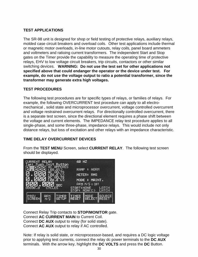
TEST APPLICATIONS The SR-98 unit is designed for shop or field testing of protective relays, auxiliary relays, molded case circuit breakers and overload coils. Other test applications include thermal or magnetic motor overloads, in-line motor cutouts, relay coils, panel board ammeters and voltmeters and ratioing current transformers. The independent Start and Stop gates on the Timer provide the capability to measure the operating time of protective relays, EHV to low voltage circuit breakers, trip circuits, contactors or other similar switching devices. WARNING: Do not use the test set for other applications not specified above that could endanger the operator or the device under test. For example, do not use the voltage output to ratio a potential transformer, since the transformer may generate extra high voltages. TEST PROCEDURES The following test procedures are for specific types of relays, or families of relays. For example, the following OVERCURRENT test procedure can apply to all electro-mechanical , solid state and microprocessor overcurrent, voltage controlled overcurrent and voltage restrained overcurrent relays. For directionally controlled overcurrent, there is a separate test screen, since the directional element requires a phase shift between the voltage and current elements. The IMPEDANCE relay test procedure applies to all single-phase, and some three-phase, impedance relays. This would include not only distance relays, but loss of excitation and other relays with an impedance characteristic. TIME DELAY OVERCURRENT DEVICES From the TEST MENU Screen, select CURRENT RELAY. The following test screen should be displayed.
Connect Relay Trip contacts to STOP/MONITOR gate. Connect AC CURRENT MAIN to Current Coil. Connect DC AUX output to relay (for solid state). Connect AC AUX output to relay if AC controlled. Note: If relay is solid state, or microprocessor-based, and requires a DC logic voltage prior to applying test currents, connect the relay dc power terminals to the DC AUX terminals. With the arrow key, highlight the DC VOLTS and press the DC Button.
31
Increase the DC voltage output by rotating the Control Knob until proper logic voltage is applied. If the relay is AC voltage controlled/restrained, see VOLTAGE RELAY Test for typical tests on the AC voltage control/restraint element. Pickup Test: 1. AC AMPERES should already be highlighted. 2. With MODE SELECT set to MAINT. (MAINTAIN), press the INIT button. 3. Rotate Control Knob and increase current until the TRIP LED turns ON (and the
horn sounds, if the horn is set on). Reduce current until TRIP LED blinks. 4. Read and record the Pick-up current. Return the current to zero. Timing Test: Preset Fault Current: 5. Pressing the MODE SELECT button, change from MAINT (Maintain) to MOM.
(Momentary) 6. Press the INIT Button. The output current should turn on for a short pulse
duration. If the current was returned to zero in step 4, the current displayed should be approximately zero.
7. Rotate the Control Knob and press the INIT Button. A new current value is
displayed. Continue until the desired current value is achieved. 8. Pressing the MODE SELECT button twice to change from MOM. (Momentary) to
CA. (Current Actuate) to MAINT (Maintain). The current value selected in Momentary mode will be remembered.
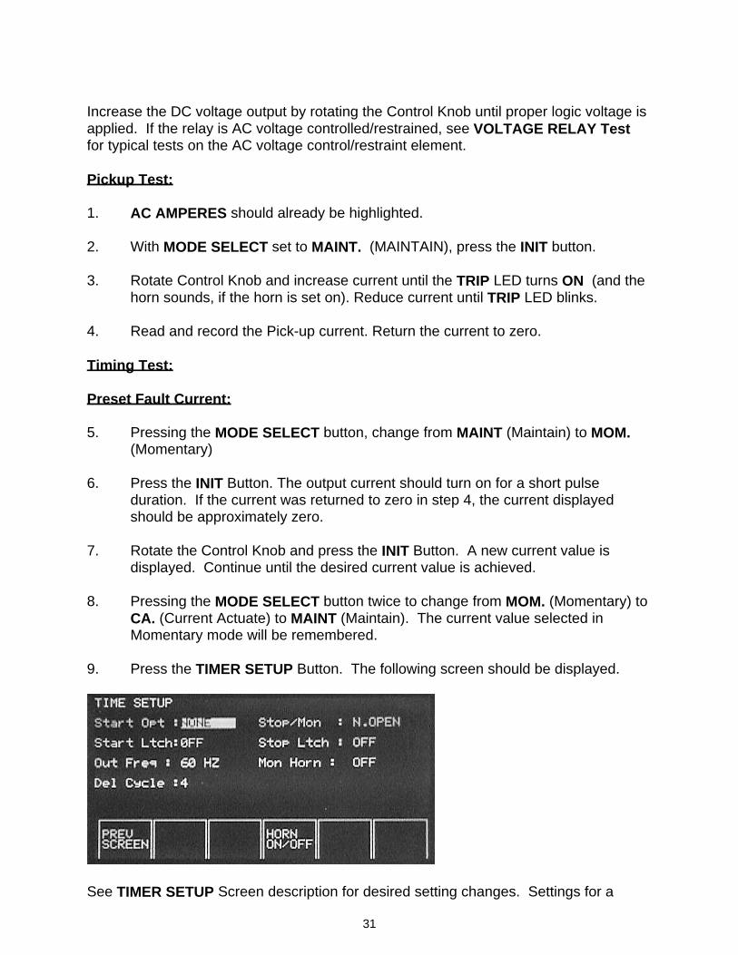
9. Press the TIMER SETUP Button. The following screen should be displayed.
See TIMER SETUP Screen description for desired setting changes. Settings for a
32
typical normally open contact timing test are as follows, 10. Select Start Option to INITIATE. 11. Select Stop Option to N. OPEN (Normally Open). 12. Select Start and Stop Latch ON. 13. Press PREV SCREEN. 14. Press the INIT Button. The current turns ON at the value set in Momentary
mode. The timer starts. Relay trips. Output turns OFF. Timer Stops. Trip LED turns ON. The horn beeps (if the horn was turned on). Record trip time.
Run Back Test: This test is normally conducted on relays, which have two sets of contacts, one associated with the trip contacts and the other associated with the back stop. 15. Connect Trip contacts to Timer Start Gate. Connect BackStop contacts to Timer Stop Gate. 16. Press the TIMER SETUP Button. Change Timer Start Option to DEINIT
(deinitiate). Change Timer Stop Option to N. OPEN. 17. With the previous test current still set from the Timing Test, press the INIT
Button. 18. The output current turns ON. When the relay trips, the output turns OFF and
starts the timer. When the backstop contacts close, the timer stops. Read and record run-back time.
33
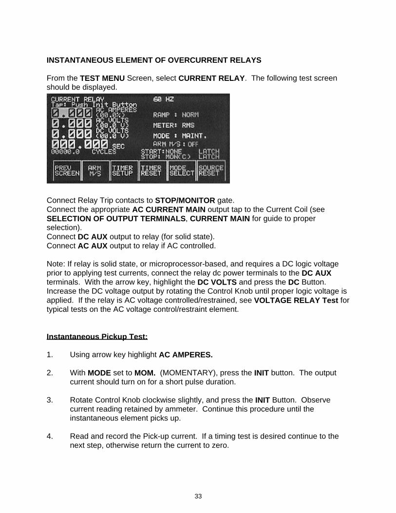
INSTANTANEOUS ELEMENT OF OVERCURRENT RELAYS From the TEST MENU Screen, select CURRENT RELAY. The following test screen should be displayed.
Connect Relay Trip contacts to STOP/MONITOR gate. Connect the appropriate AC CURRENT MAIN output tap to the Current Coil (see SELECTION OF OUTPUT TERMINALS, CURRENT MAIN for guide to proper selection). Connect DC AUX output to relay (for solid state). Connect AC AUX output to relay if AC controlled. Note: If relay is solid state, or microprocessor-based, and requires a DC logic voltage prior to applying test currents, connect the relay dc power terminals to the DC AUX terminals. With the arrow key, highlight the DC VOLTS and press the DC Button. Increase the DC voltage output by rotating the Control Knob until proper logic voltage is applied. If the relay is AC voltage controlled/restrained, see VOLTAGE RELAY Test for typical tests on the AC voltage control/restraint element. Instantaneous Pickup Test: 1. Using arrow key highlight AC AMPERES. 2. With MODE set to MOM. (MOMENTARY), press the INIT button. The output
current should turn on for a short pulse duration. 3. Rotate Control Knob clockwise slightly, and press the INIT Button. Observe
current reading retained by ammeter. Continue this procedure until the instantaneous element picks up.
4. Read and record the Pick-up current. If a timing test is desired continue to the next step, otherwise return the current to zero.
34
Timing Test of Instantaneous Overcurrent Element 1. To time the instantaneous element, repeat steps 7 through 14 for Timing Test,
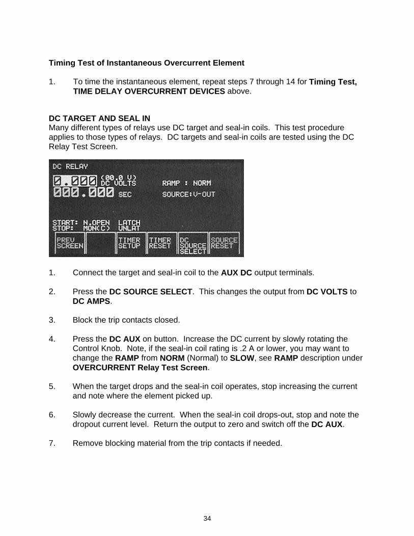
TIME DELAY OVERCURRENT DEVICES above. DC TARGET AND SEAL IN Many different types of relays use DC target and seal-in coils. This test procedure applies to those types of relays. DC targets and seal-in coils are tested using the DC Relay Test Screen.
1. Connect the target and seal-in coil to the AUX DC output terminals. 2. Press the DC SOURCE SELECT. This changes the output from DC VOLTS to
DC AMPS. 3. Block the trip contacts closed. 4. Press the DC AUX on button. Increase the DC current by slowly rotating the
Control Knob. Note, if the seal-in coil rating is .2 A or lower, you may want to change the RAMP from NORM (Normal) to SLOW, see RAMP description under OVERCURRENT Relay Test Screen.
5. When the target drops and the seal-in coil operates, stop increasing the current
and note where the element picked up. 6. Slowly decrease the current. When the seal-in coil drops-out, stop and note the
dropout current level. Return the output to zero and switch off the DC AUX. 7. Remove blocking material from the trip contacts if needed.
35
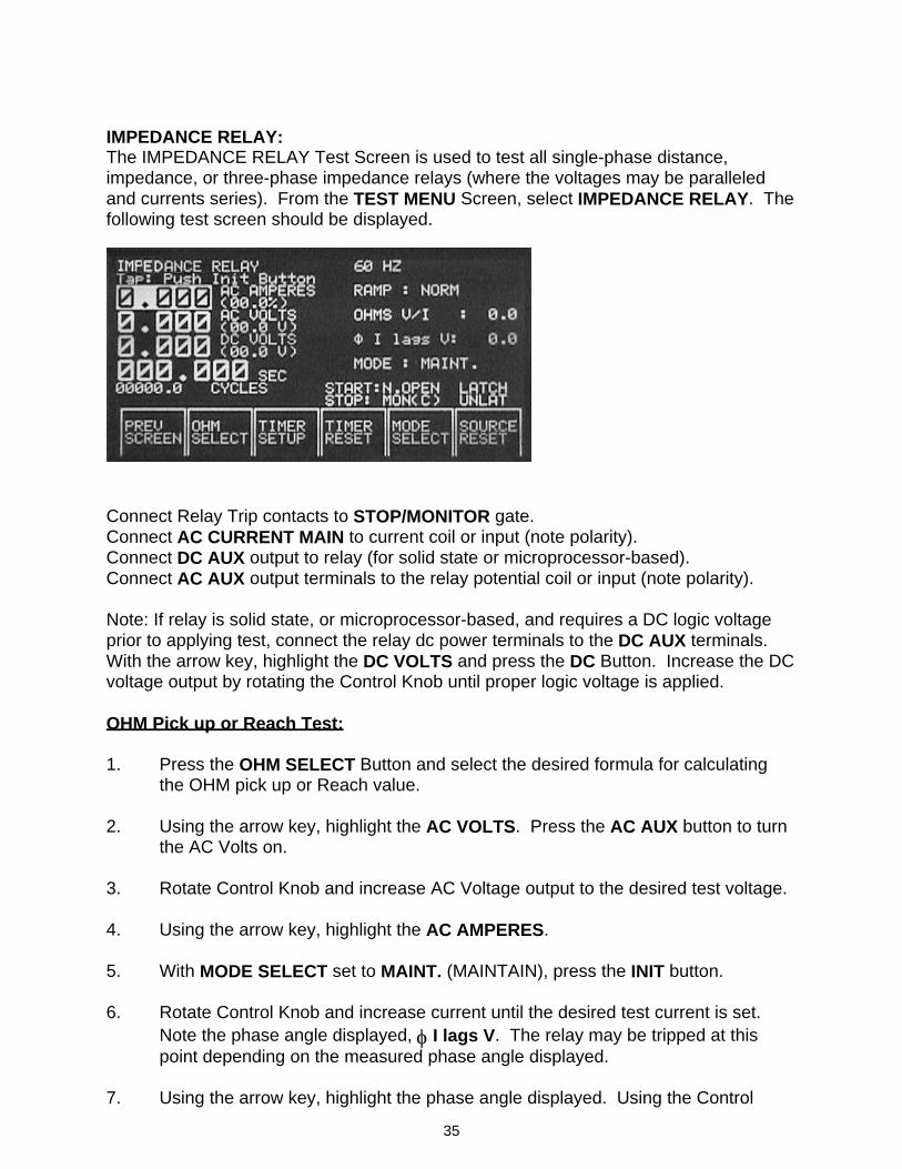
IMPEDANCE RELAY: The IMPEDANCE RELAY Test Screen is used to test all single-phase distance, impedance, or three-phase impedance relays (where the voltages may be paralleled and currents series). From the TEST MENU Screen, select IMPEDANCE RELAY. The following test screen should be displayed.
Connect Relay Trip contacts to STOP/MONITOR gate. Connect AC CURRENT MAIN to current coil or input (note polarity). Connect DC AUX output to relay (for solid state or microprocessor-based). Connect AC AUX output terminals to the relay potential coil or input (note polarity). Note: If relay is solid state, or microprocessor-based, and requires a DC logic voltage prior to applying test, connect the relay dc power terminals to the DC AUX terminals. With the arrow key, highlight the DC VOLTS and press the DC Button. Increase the DC voltage output by rotating the Control Knob until proper logic voltage is applied. OHM Pick up or Reach Test: 1. Press the OHM SELECT Button and select the desired formula for calculating
the OHM pick up or Reach value. 2. Using the arrow key, highlight the AC VOLTS. Press the AC AUX button to turn
the AC Volts on. 3. Rotate Control Knob and increase AC Voltage output to the desired test voltage. 4. Using the arrow key, highlight the AC AMPERES. 5. With MODE SELECT set to MAINT. (MAINTAIN), press the INIT button. 6. Rotate Control Knob and increase current until the desired test current is set.
Note the phase angle displayed, φ I lags V. The relay may be tripped at this point depending on the measured phase angle displayed.
7. Using the arrow key, highlight the phase angle displayed. Using the Control
36
Knob, rotate the phase angle to the desired angle (note current lags voltage). 8. Using the arrow key, highlight either AC AMPERES or AC VOLTS. Using the
Control Knob, decrease the AC Volts (or increase the AC Current) until the TRIP LED turns on. Read and record the OHMS value displayed.
Max ∠τ (Angle of Torque) Test: 9. Continue decreasing the AC Voltage (or increasing the AC Current) until well
inside the operating characteristic (TRIP LED stays ON). 10. Using the arrow key, highlight the phase angle display. Using the Control Knob,
vary the Phase Angle clockwise until the contacts open and the LED turns OFF. Note the Phase Angle (θ1). 11. Vary the Phase Angle counter-clockwise. The LED will turn ON again indicating that we are inside the operating characteristic. Continue moving in the counter-clockwise direction until the LED turns OFF again. Note the Phase Angle (θ2). MAX ∠τ = (θ1+ θ2) / 2
37
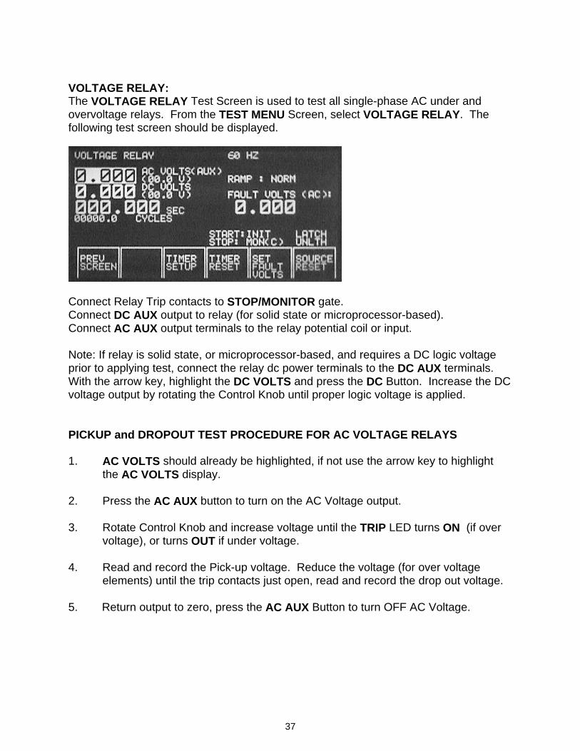
VOLTAGE RELAY: The VOLTAGE RELAY Test Screen is used to test all single-phase AC under and overvoltage relays. From the TEST MENU Screen, select VOLTAGE RELAY. The following test screen should be displayed.
Connect Relay Trip contacts to STOP/MONITOR gate. Connect DC AUX output to relay (for solid state or microprocessor-based). Connect AC AUX output terminals to the relay potential coil or input. Note: If relay is solid state, or microprocessor-based, and requires a DC logic voltage prior to applying test, connect the relay dc power terminals to the DC AUX terminals. With the arrow key, highlight the DC VOLTS and press the DC Button. Increase the DC voltage output by rotating the Control Knob until proper logic voltage is applied. PICKUP and DROPOUT TEST PROCEDURE FOR AC VOLTAGE RELAYS 1. AC VOLTS should already be highlighted, if not use the arrow key to highlight
the AC VOLTS display. 2. Press the AC AUX button to turn on the AC Voltage output. 3. Rotate Control Knob and increase voltage until the TRIP LED turns ON (if over
voltage), or turns OUT if under voltage. 4. Read and record the Pick-up voltage. Reduce the voltage (for over voltage
elements) until the trip contacts just open, read and record the drop out voltage. 5. Return output to zero, press the AC AUX Button to turn OFF AC Voltage.
38
VOLTAGE RELAY TIMING TEST 1. With the relay properly connected to the test set (see connections above) press
the AC AUX Button to turn the AC output voltage on. 2. The “fault” voltage is set first. Increase the “fault” voltage to the relay by rotating
the Control Knob. Set the fault voltage by pressing the SET FAULT VOLTS Button.
3. Increase or decrease the AC AUX output voltage by rotating the Control Knob to
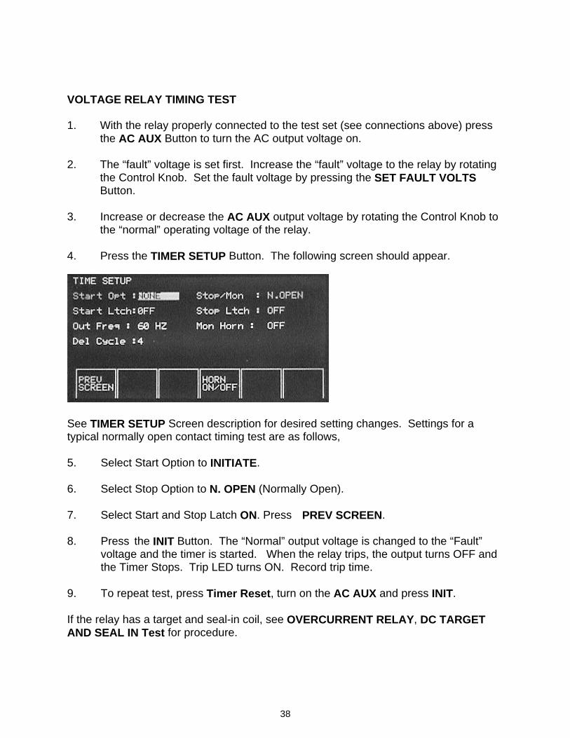
the “normal” operating voltage of the relay. 4. Press the TIMER SETUP Button. The following screen should appear.
See TIMER SETUP Screen description for desired setting changes. Settings for a typical normally open contact timing test are as follows, 5. Select Start Option to INITIATE. 6. Select Stop Option to N. OPEN (Normally Open). 7. Select Start and Stop Latch ON. Press PREV SCREEN. 8. Press the INIT Button. The “Normal” output voltage is changed to the “Fault”
voltage and the timer is started. When the relay trips, the output turns OFF and the Timer Stops. Trip LED turns ON. Record trip time.
9. To repeat test, press Timer Reset, turn on the AC AUX and press INIT. If the relay has a target and seal-in coil, see OVERCURRENT RELAY, DC TARGET AND SEAL IN Test for procedure.
39
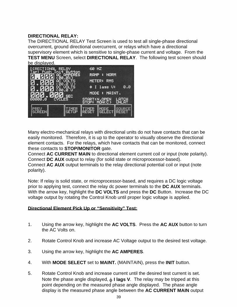
DIRECTIONAL RELAY: The DIRECTIONAL RELAY Test Screen is used to test all single-phase directional overcurrent, ground directional overcurrent, or relays which have a directional supervisory element which is sensitive to single-phase current and voltage. From the TEST MENU Screen, select DIRECTIONAL RELAY. The following test screen should be displayed.
Many electro-mechanical relays with directional units do not have contacts that can be easily monitored. Therefore, it is up to the operator to visually observe the directional element contacts. For the relays, which have contacts that can be monitored, connect these contacts to STOP/MONITOR gate. Connect AC CURRENT MAIN to directional element current coil or input (note polarity). Connect DC AUX output to relay (for solid state or microprocessor-based). Connect AC AUX output terminals to the relay directional potential coil or input (note polarity). Note: If relay is solid state, or microprocessor-based, and requires a DC logic voltage prior to applying test, connect the relay dc power terminals to the DC AUX terminals. With the arrow key, highlight the DC VOLTS and press the DC Button. Increase the DC voltage output by rotating the Control Knob until proper logic voltage is applied. Directional Element Pick Up or “Sensitivity” Test: 1. Using the arrow key, highlight the AC VOLTS. Press the AC AUX button to turn
the AC Volts on. 2. Rotate Control Knob and increase AC Voltage output to the desired test voltage. 3. Using the arrow key, highlight the AC AMPERES. 4. With MODE SELECT set to MAINT. (MAINTAIN), press the INIT button. 5. Rotate Control Knob and increase current until the desired test current is set.
Note the phase angle displayed, φ I lags V. The relay may be tripped at this point depending on the measured phase angle displayed. The phase angle display is the measured phase angle between the AC CURRENT MAIN output
40
and the AC AUX Output. It displays Current lagging Voltage. Since some directional elements are tested with current leading the voltage, simply subtract the angle indicated from 360 to get the appropriate leading angle. For example, if the test is to be conducted at 30 degrees current leading voltage, set the phase angle to 330 degrees (330 current lags voltage equals 30 degrees current leads voltage).
6. Using the arrow key, highlight the phase angle displayed. Using the Control
Knob, rotate the phase angle to the desired angle (note current lags voltage). 7. Using the arrow key, highlight either AC AMPERES or AC VOLTS. Using the
Control Knob, decrease the AC Volts (or increase the AC Current) until the directional contacts just close. Note the voltage, current and phase angle. Record pick up values.
Max ∠τ (Angle of Torque) Test: 8. Continue decreasing the AC Voltage (or increasing the AC Current) slightly until
well across the operating characteristic (directional contacts are closed). 9. Using the arrow key, highlight the phase angle display. Using the Control Knob,
vary the Phase Angle clockwise until the contacts open and the directional contacts open. Note the Phase Angle (θ1).
10. Vary the Phase Angle counter-clockwise. The contacts will close again
indicating that we are across the operating characteristic. Continue moving in the counter-clockwise direction until the contacts just open again. Note the Phase Angle (θ2). To calculate the maximum angle of torque, convert the larger of the two lagging angles to a leading angle and add, then divide by two.
MAX ∠τ = (θ1+ θ2) / 2 For example, if the relay has a maximum angle of torque at 30 degrees current leading voltage, typical recorded phase angles could be 240 and 60, current lagging voltage. Converting 240 to a leading angle, results in an angle of 120 degrees current leading voltage. Adding the two angles and dividing by 2 results in a value of 30 degrees, MAX ∠τ = (120 lead + (-60 lag)) / 2 MAX ∠τ = 60 / 2 or 30 degrees Leading To test overcurrent unit, block the directional contacts closed and use the OVERCURRENT RELAY procedure for pick up and timing tests
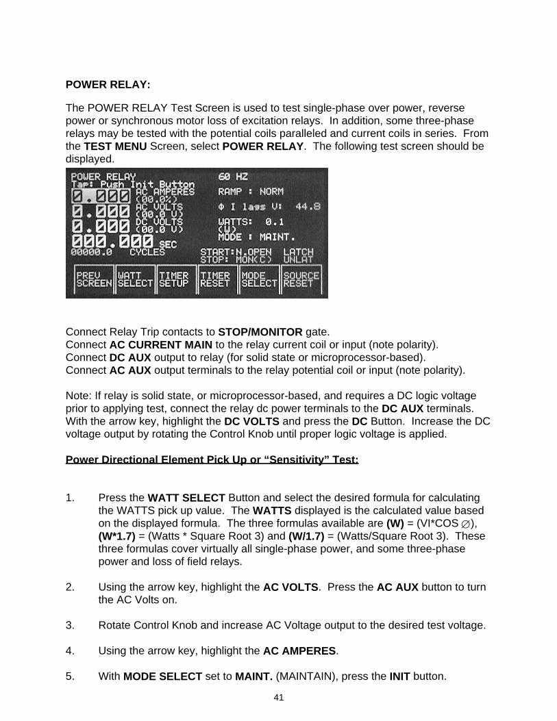
41
POWER RELAY: The POWER RELAY Test Screen is used to test single-phase over power, reverse power or synchronous motor loss of excitation relays. In addition, some three-phase relays may be tested with the potential coils paralleled and current coils in series. From the TEST MENU Screen, select POWER RELAY. The following test screen should be displayed.
Connect Relay Trip contacts to STOP/MONITOR gate. Connect AC CURRENT MAIN to the relay current coil or input (note polarity). Connect DC AUX output to relay (for solid state or microprocessor-based). Connect AC AUX output terminals to the relay potential coil or input (note polarity). Note: If relay is solid state, or microprocessor-based, and requires a DC logic voltage prior to applying test, connect the relay dc power terminals to the DC AUX terminals. With the arrow key, highlight the DC VOLTS and press the DC Button. Increase the DC voltage output by rotating the Control Knob until proper logic voltage is applied. Power Directional Element Pick Up or “Sensitivity” Test: 1. Press the WATT SELECT Button and select the desired formula for calculating
the WATTS pick up value. The WATTS displayed is the calculated value based on the displayed formula. The three formulas available are (W) = (VI*COS ∅), (W*1.7) = (Watts * Square Root 3) and (W/1.7) = (Watts/Square Root 3). These three formulas cover virtually all single-phase power, and some three-phase power and loss of field relays.
2. Using the arrow key, highlight the AC VOLTS. Press the AC AUX button to turn
the AC Volts on. 3. Rotate Control Knob and increase AC Voltage output to the desired test voltage. 4. Using the arrow key, highlight the AC AMPERES. 5. With MODE SELECT set to MAINT. (MAINTAIN), press the INIT button.
42
6. Rotate Control Knob and increase current until the desired test current is set.
Note the phase angle displayed, φ I lags V. The relay may be tripped at this point depending on the measured phase angle displayed. The phase angle display is the measured phase angle between the AC CURRENT MAIN output and the AC AUX Output. It displays Current lagging Voltage. Since some power directional elements are tested with current leading the voltage, simply subtract the angle indicated from 360 to get the appropriate leading angle. For example, if the test is to be conducted at 30 degrees current leading voltage, set the phase angle to 330 degrees (330 current lags voltage equals 30 degrees current leads voltage).
7. Using the arrow key, highlight the phase angle displayed. Using the Control
Knob, rotate the phase angle to the desired test angle. 8. Using the arrow key, highlight either AC AMPERES or AC VOLTS. Using the
Control Knob, decrease the AC Volts (or increase the AC Current) until the trip contacts just close. Read and record the WATTS indicated for pick up value.
Max ∠τ (Angle of Torque) Test: 9. Continue decreasing the AC Voltage (or increasing the AC Current) slightly until
well across the operating characteristic line (trip contacts are closed). 10. Using the arrow key, highlight the phase angle display. Using the Control Knob,
vary the Phase Angle clockwise until the contacts open. Note the Phase Angle (θ1).
11. Vary the Phase Angle counter-clockwise. The contacts will close again
indicating that we are across the operating characteristic. Continue moving in the counter-clockwise direction until the contacts just open again. Note the Phase Angle (θ2). To calculate the maximum angle of torque, convert the larger of the two lagging angles to a leading angle and add, then divide by two.
MAX ∠τ = (θ1+ θ2) / 2 For example, if the relay has a maximum angle of torque at 30 degrees current leading voltage, typical recorded phase angles could be 240 and 60, current lagging voltage. Converting 240 to a leading angle, results in an angle of 120 degrees current leading voltage. Adding the two angles and dividing by 2 results in a value of 30 degrees, MAX ∠τ = (120 lead + (-60 lag)) / 2 ⇒ MAX ∠τ = 60 / 2 or 30 degrees Leading
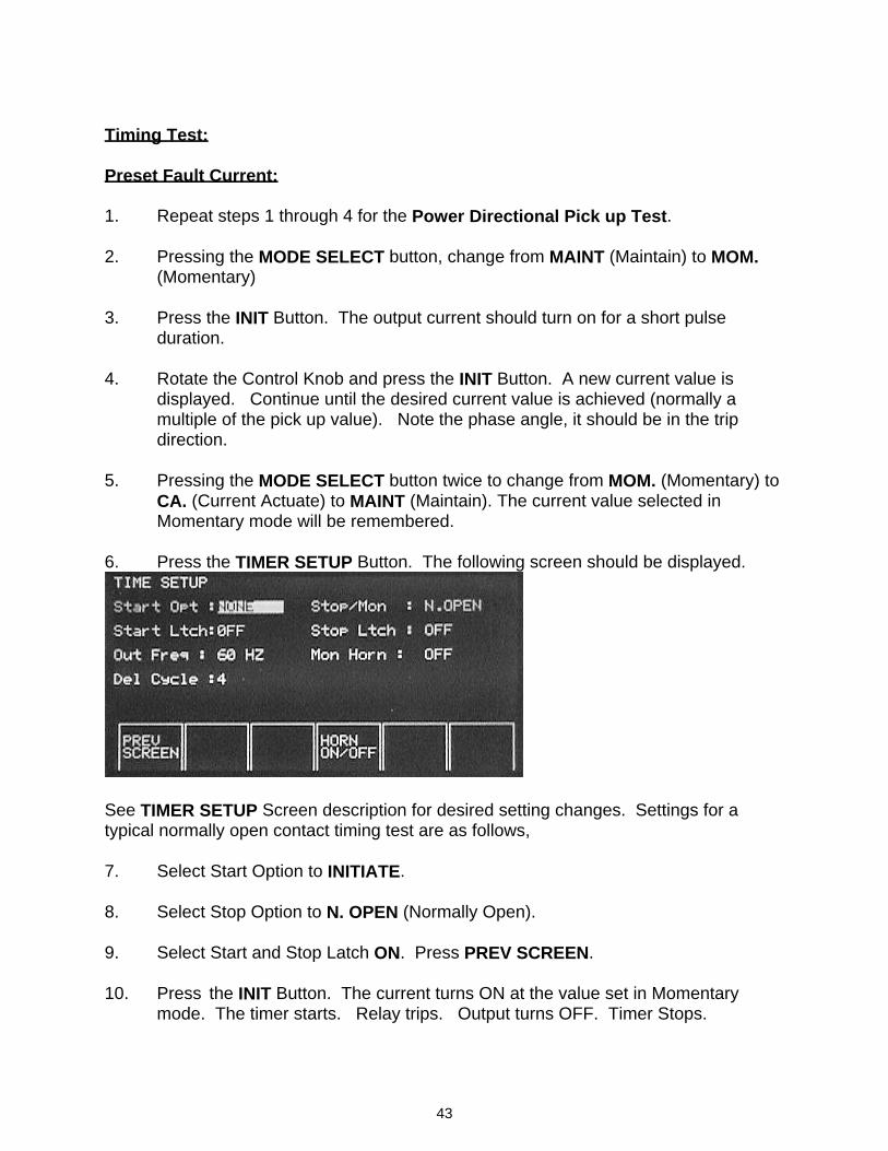
43
Timing Test: Preset Fault Current: 1. Repeat steps 1 through 4 for the Power Directional Pick up Test. 2. Pressing the MODE SELECT button, change from MAINT (Maintain) to MOM.
(Momentary) 3. Press the INIT Button. The output current should turn on for a short pulse
duration. 4. Rotate the Control Knob and press the INIT Button. A new current value is
displayed. Continue until the desired current value is achieved (normally a multiple of the pick up value). Note the phase angle, it should be in the trip direction.
5. Pressing the MODE SELECT button twice to change from MOM. (Momentary) to
CA. (Current Actuate) to MAINT (Maintain). The current value selected in Momentary mode will be remembered.
6. Press the TIMER SETUP Button. The following screen should be displayed.
See TIMER SETUP Screen description for desired setting changes. Settings for a typical normally open contact timing test are as follows, 7. Select Start Option to INITIATE. 8. Select Stop Option to N. OPEN (Normally Open). 9. Select Start and Stop Latch ON. Press PREV SCREEN. 10. Press the INIT Button. The current turns ON at the value set in Momentary
mode. The timer starts. Relay trips. Output turns OFF. Timer Stops.
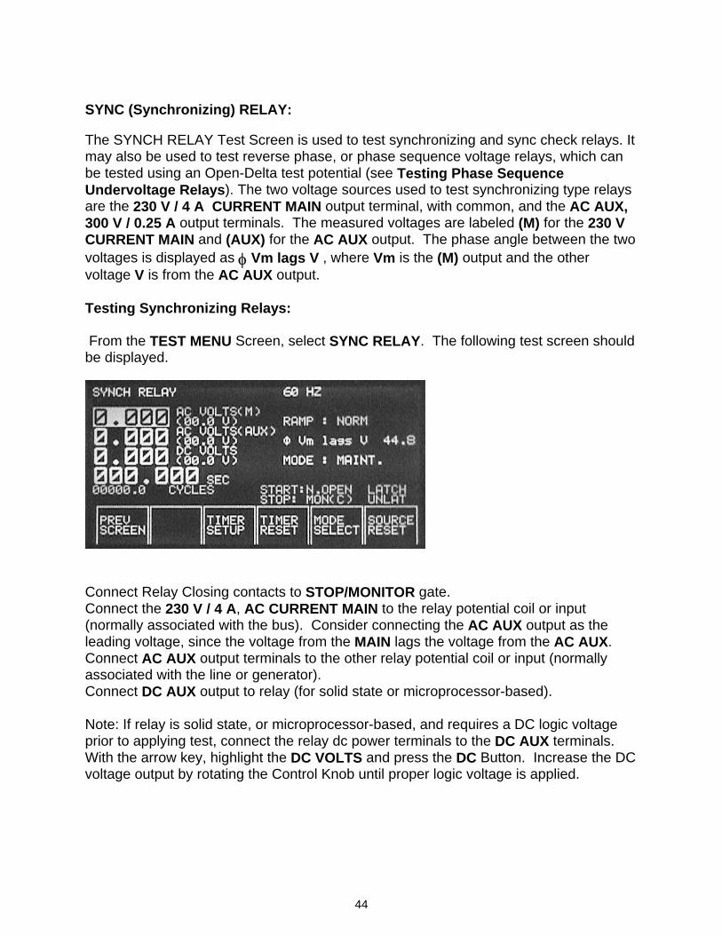
44
SYNC (Synchronizing) RELAY: The SYNCH RELAY Test Screen is used to test synchronizing and sync check relays. It may also be used to test reverse phase, or phase sequence voltage relays, which can be tested using an Open-Delta test potential (see Testing Phase Sequence Undervoltage Relays). The two voltage sources used to test synchronizing type relays are the 230 V / 4 A CURRENT MAIN output terminal, with common, and the AC AUX, 300 V / 0.25 A output terminals. The measured voltages are labeled (M) for the 230 V CURRENT MAIN and (AUX) for the AC AUX output. The phase angle between the two voltages is displayed as φ Vm lags V , where Vm is the (M) output and the other voltage V is from the AC AUX output. Testing Synchronizing Relays: From the TEST MENU Screen, select SYNC RELAY. The following test screen should be displayed.
Connect Relay Closing contacts to STOP/MONITOR gate. Connect the 230 V / 4 A, AC CURRENT MAIN to the relay potential coil or input (normally associated with the bus). Consider connecting the AC AUX output as the leading voltage, since the voltage from the MAIN lags the voltage from the AC AUX. Connect AC AUX output terminals to the other relay potential coil or input (normally associated with the line or generator). Connect DC AUX output to relay (for solid state or microprocessor-based). Note: If relay is solid state, or microprocessor-based, and requires a DC logic voltage prior to applying test, connect the relay dc power terminals to the DC AUX terminals. With the arrow key, highlight the DC VOLTS and press the DC Button. Increase the DC voltage output by rotating the Control Knob until proper logic voltage is applied.
45
Pick Up and Drop Out Test: 1. Press the INIT button to turn on the AC VOLTS (M) voltage source. 2. Rotate Control Knob until rated voltage appears on the AC VOLTS (M) display. 3. Using the arrow key, highlight the AC VOLTS (AUX). Press the AC AUX button
to turn the AC Volts on. 4. Rotate Control Knob and increase AUX AC Voltage output to the desired test
voltage. Note the phase angle displayed, V(M) lags V (AUX). The relay may be closed at this point depending on the measured phase angle displayed.
5. Using the arrow key, highlight the phase angle displayed. Using the Control
Knob, rotate the phase angle to the desired test angle (normally zero degrees). 5. Using the arrow key, highlight AC VOLTS (AUX). Using the Control Knob, adjust
the AC AUX Volts until the contacts just close (for pick up). Record the pick up value.
7. Continue to increase voltage until contacts just open (for drop out). Record the
drop out value. Closing Angle (Operating Angle) Test: 8. Decrease the AC AUX Voltage back to the rated voltage (the closing contacts
should be closed). 9. Using the arrow key, highlight the phase angle display. Using the Control Knob,
adjust the Phase Angle clockwise until the contacts just open. Note the Phase Angle (θ1).
10. Vary the Phase Angle counter-clockwise. The contacts will close again
indicating that we are in the operating characteristic. Continue moving in the counter-clockwise direction until the contacts just open again. Note the Phase Angle (θ2).
For example, if the relay has a closing characteristic angle of 20 degrees, typical recorded phase angles should be 340 degrees (20 degrees leading) and 20 degrees (lagging).
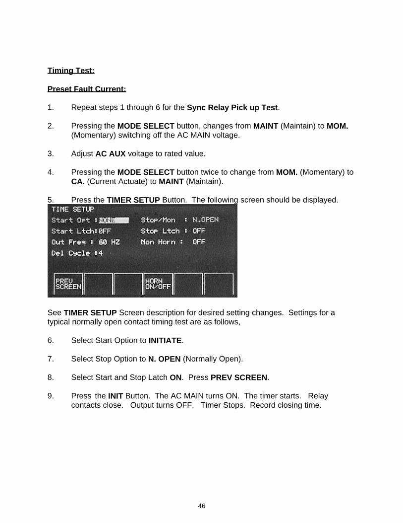
46
Timing Test: Preset Fault Current: 1. Repeat steps 1 through 6 for the Sync Relay Pick up Test. 2. Pressing the MODE SELECT button, changes from MAINT (Maintain) to MOM.
(Momentary) switching off the AC MAIN voltage. 3. Adjust AC AUX voltage to rated value. 4. Pressing the MODE SELECT button twice to change from MOM. (Momentary) to
CA. (Current Actuate) to MAINT (Maintain). 5. Press the TIMER SETUP Button. The following screen should be displayed.
See TIMER SETUP Screen description for desired setting changes. Settings for a typical normally open contact timing test are as follows, 6. Select Start Option to INITIATE. 7. Select Stop Option to N. OPEN (Normally Open). 8. Select Start and Stop Latch ON. Press PREV SCREEN. 9. Press the INIT Button. The AC MAIN turns ON. The timer starts. Relay
contacts close. Output turns OFF. Timer Stops. Record closing time.
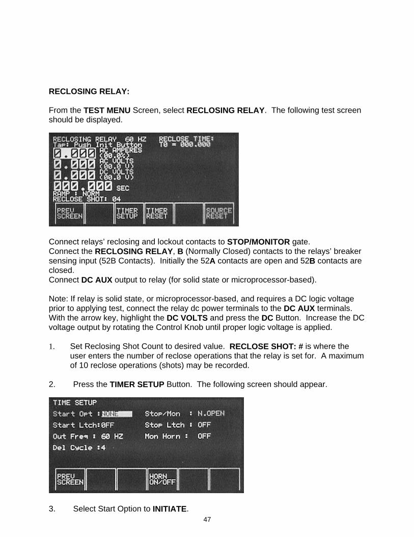
47
RECLOSING RELAY: From the TEST MENU Screen, select RECLOSING RELAY. The following test screen should be displayed.
Connect relays’ reclosing and lockout contacts to STOP/MONITOR gate. Connect the RECLOSING RELAY, B (Normally Closed) contacts to the relays’ breaker sensing input (52B Contacts). Initially the 52A contacts are open and 52B contacts are closed. Connect DC AUX output to relay (for solid state or microprocessor-based). Note: If relay is solid state, or microprocessor-based, and requires a DC logic voltage prior to applying test, connect the relay dc power terminals to the DC AUX terminals. With the arrow key, highlight the DC VOLTS and press the DC Button. Increase the DC voltage output by rotating the Control Knob until proper logic voltage is applied. 1. Set Reclosing Shot Count to desired value. RECLOSE SHOT: # is where the
user enters the number of reclose operations that the relay is set for. A maximum of 10 reclose operations (shots) may be recorded.
2. Press the TIMER SETUP Button. The following screen should appear.
3. Select Start Option to INITIATE.
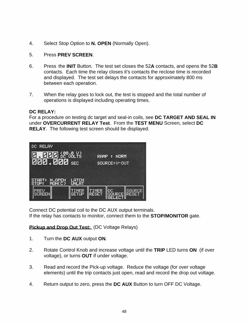
48
4. Select Stop Option to N. OPEN (Normally Open). 5. Press PREV SCREEN. 6. Press the INIT Button. The test set closes the 52A contacts, and opens the 52B
contacts. Each time the relay closes it’s contacts the reclose time is recorded and displayed. The test set delays the contacts for approximately 800 ms between each operation.
7. When the relay goes to lock out, the test is stopped and the total number of
operations is displayed including operating times. DC RELAY: For a procedure on testing dc target and seal-in coils, see DC TARGET AND SEAL IN under OVERCURRENT RELAY Test. From the TEST MENU Screen, select DC RELAY. The following test screen should be displayed.
Connect DC potential coil to the DC AUX output terminals. If the relay has contacts to monitor, connect them to the STOP/MONITOR gate. Pickup and Drop Out Test: (DC Voltage Relays) 1. Turn the DC AUX output ON. 2. Rotate Control Knob and increase voltage until the TRIP LED turns ON (if over
voltage), or turns OUT if under voltage. 3. Read and record the Pick-up voltage. Reduce the voltage (for over voltage
elements) until the trip contacts just open, read and record the drop out voltage. 4. Return output to zero, press the DC AUX Button to turn OFF DC Voltage.
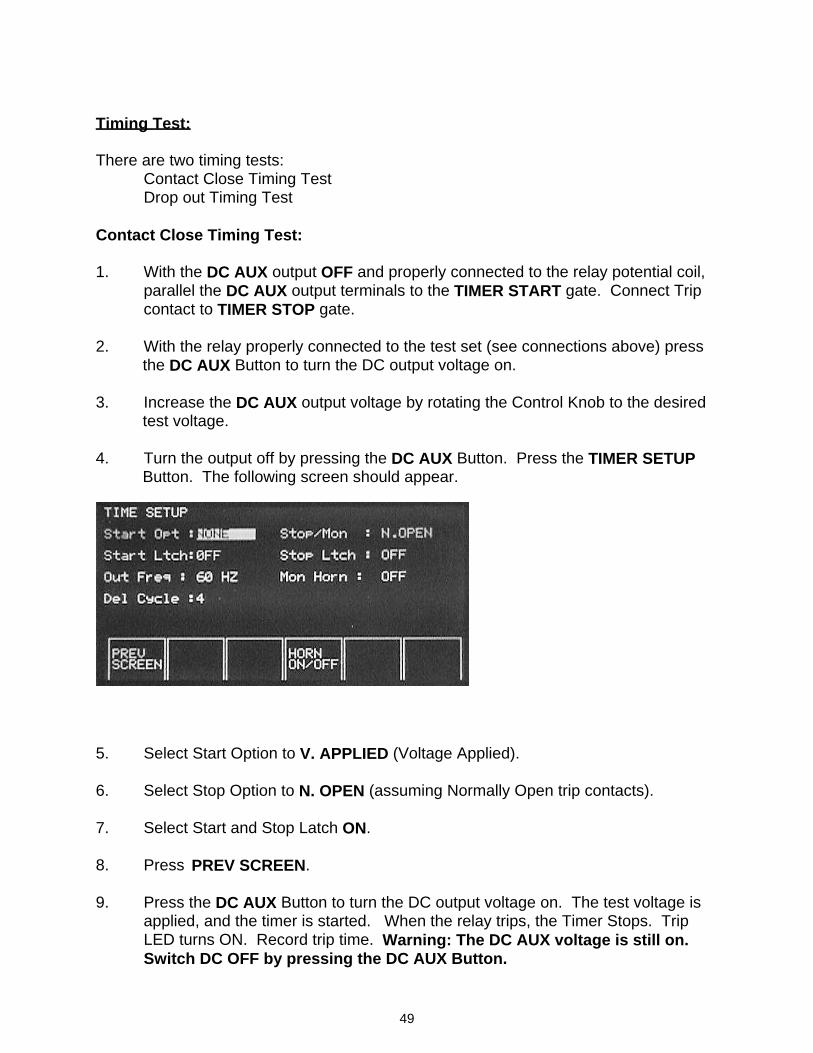
49
Timing Test: There are two timing tests: Contact Close Timing Test Drop out Timing Test Contact Close Timing Test: 1. With the DC AUX output OFF and properly connected to the relay potential coil,
parallel the DC AUX output terminals to the TIMER START gate. Connect Trip contact to TIMER STOP gate.
2. With the relay properly connected to the test set (see connections above) press
the DC AUX Button to turn the DC output voltage on. 3. Increase the DC AUX output voltage by rotating the Control Knob to the desired
test voltage. 4. Turn the output off by pressing the DC AUX Button. Press the TIMER SETUP
Button. The following screen should appear.
5. Select Start Option to V. APPLIED (Voltage Applied). 6. Select Stop Option to N. OPEN (assuming Normally Open trip contacts). 7. Select Start and Stop Latch ON. 8. Press PREV SCREEN. 9. Press the DC AUX Button to turn the DC output voltage on. The test voltage is
applied, and the timer is started. When the relay trips, the Timer Stops. Trip LED turns ON. Record trip time. Warning: The DC AUX voltage is still on. Switch DC OFF by pressing the DC AUX Button.
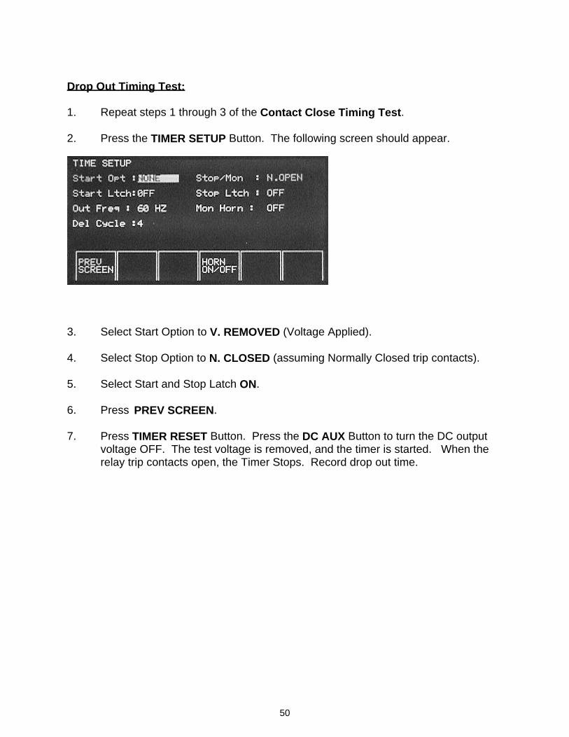
50
Drop Out Timing Test: 1. Repeat steps 1 through 3 of the Contact Close Timing Test. 2. Press the TIMER SETUP Button. The following screen should appear.
3. Select Start Option to V. REMOVED (Voltage Applied). 4. Select Stop Option to N. CLOSED (assuming Normally Closed trip contacts). 5. Select Start and Stop Latch ON. 6. Press PREV SCREEN. 7. Press TIMER RESET Button. Press the DC AUX Button to turn the DC output
voltage OFF. The test voltage is removed, and the timer is started. When the relay trip contacts open, the Timer Stops. Record drop out time.
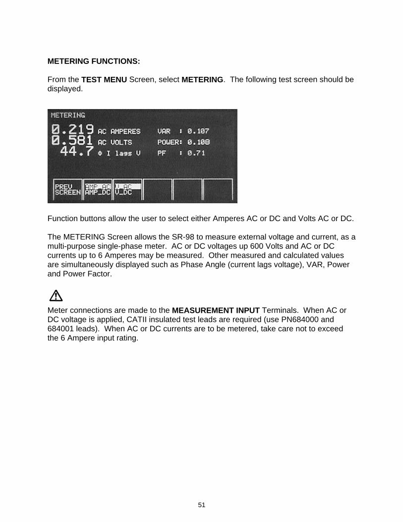
51
METERING FUNCTIONS: From the TEST MENU Screen, select METERING. The following test screen should be displayed.
Function buttons allow the user to select either Amperes AC or DC and Volts AC or DC. The METERING Screen allows the SR-98 to measure external voltage and current, as a multi-purpose single-phase meter. AC or DC voltages up 600 Volts and AC or DC currents up to 6 Amperes may be measured. Other measured and calculated values are simultaneously displayed such as Phase Angle (current lags voltage), VAR, Power and Power Factor.
Meter connections are made to the MEASUREMENT INPUT Terminals. When AC or DC voltage is applied, CATII insulated test leads are required (use PN684000 and 684001 leads). When AC or DC currents are to be metered, take care not to exceed the 6 Ampere input rating.
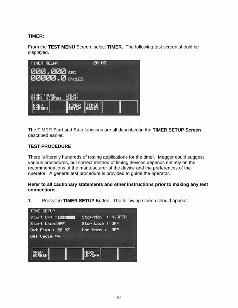
52
TIMER: From the TEST MENU Screen, select TIMER. The following test screen should be displayed.
The TIMER Start and Stop functions are all described in the TIMER SETUP Screen described earlier. TEST PROCEDURE There is literally hundreds of testing applications for the timer. Megger could suggest various procedures, but correct method of timing devices depends entirely on the recommendations of the manufacturer of the device and the preferences of the operator. A general test procedure is provided to guide the operator. Refer to all cautionary statements and other instructions prior to making any test connections. 1. Press the TIMER SETUP Button. The following screen should appear.
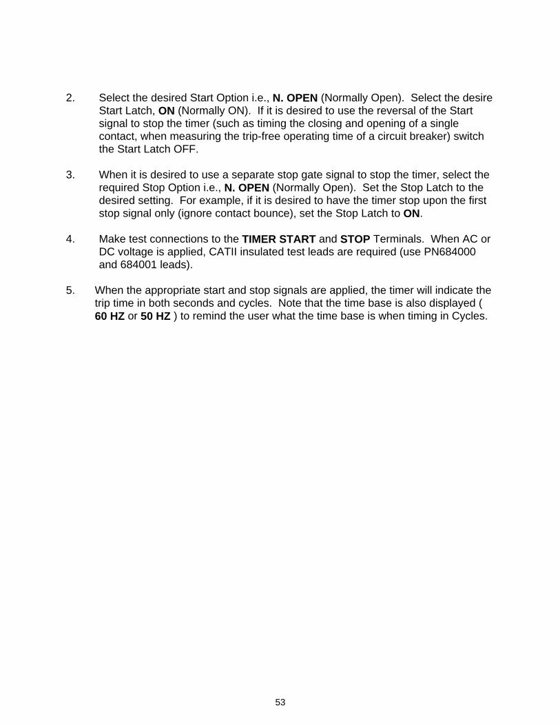
53
2. Select the desired Start Option i.e., N. OPEN (Normally Open). Select the desire
Start Latch, ON (Normally ON). If it is desired to use the reversal of the Start signal to stop the timer (such as timing the closing and opening of a single contact, when measuring the trip-free operating time of a circuit breaker) switch the Start Latch OFF.
3. When it is desired to use a separate stop gate signal to stop the timer, select the
required Stop Option i.e., N. OPEN (Normally Open). Set the Stop Latch to the desired setting. For example, if it is desired to have the timer stop upon the first stop signal only (ignore contact bounce), set the Stop Latch to ON.
4. Make test connections to the TIMER START and STOP Terminals. When AC or
DC voltage is applied, CATII insulated test leads are required (use PN684000 and 684001 leads).
5. When the appropriate start and stop signals are applied, the timer will indicate the
trip time in both seconds and cycles. Note that the time base is also displayed ( 60 HZ or 50 HZ ) to remind the user what the time base is when timing in Cycles.
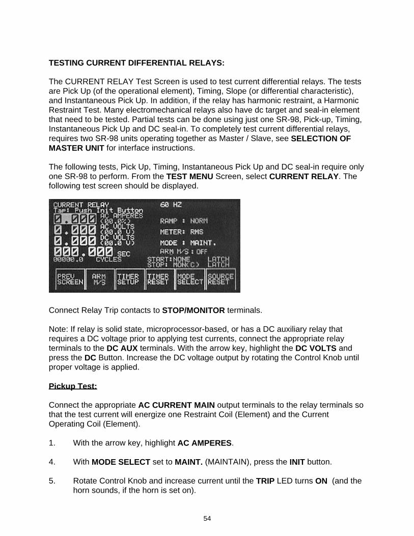
54
TESTING CURRENT DIFFERENTIAL RELAYS: The CURRENT RELAY Test Screen is used to test current differential relays. The tests are Pick Up (of the operational element), Timing, Slope (or differential characteristic), and Instantaneous Pick Up. In addition, if the relay has harmonic restraint, a Harmonic Restraint Test. Many electromechanical relays also have dc target and seal-in element that need to be tested. Partial tests can be done using just one SR-98, Pick-up, Timing, Instantaneous Pick Up and DC seal-in. To completely test current differential relays, requires two SR-98 units operating together as Master / Slave, see SELECTION OF MASTER UNIT for interface instructions. The following tests, Pick Up, Timing, Instantaneous Pick Up and DC seal-in require only one SR-98 to perform. From the TEST MENU Screen, select CURRENT RELAY. The following test screen should be displayed.
Connect Relay Trip contacts to STOP/MONITOR terminals. Note: If relay is solid state, microprocessor-based, or has a DC auxiliary relay that requires a DC voltage prior to applying test currents, connect the appropriate relay terminals to the DC AUX terminals. With the arrow key, highlight the DC VOLTS and press the DC Button. Increase the DC voltage output by rotating the Control Knob until proper voltage is applied. Pickup Test: Connect the appropriate AC CURRENT MAIN output terminals to the relay terminals so that the test current will energize one Restraint Coil (Element) and the Current Operating Coil (Element). 1. With the arrow key, highlight AC AMPERES. 4. With MODE SELECT set to MAINT. (MAINTAIN), press the INIT button. 5. Rotate Control Knob and increase current until the TRIP LED turns ON (and the
horn sounds, if the horn is set on).
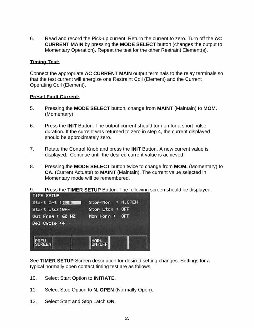
55
6. Read and record the Pick-up current. Return the current to zero. Turn off the AC CURRENT MAIN by pressing the MODE SELECT button (changes the output to Momentary Operation). Repeat the test for the other Restraint Element(s).
Timing Test: Connect the appropriate AC CURRENT MAIN output terminals to the relay terminals so that the test current will energize one Restraint Coil (Element) and the Current Operating Coil (Element). Preset Fault Current: 5. Pressing the MODE SELECT button, change from MAINT (Maintain) to MOM.
(Momentary) 6. Press the INIT Button. The output current should turn on for a short pulse
duration. If the current was returned to zero in step 4, the current displayed should be approximately zero.
7. Rotate the Control Knob and press the INIT Button. A new current value is
displayed. Continue until the desired current value is achieved. 8. Pressing the MODE SELECT button twice to change from MOM. (Momentary) to
CA. (Current Actuate) to MAINT (Maintain). The current value selected in Momentary mode will be remembered.
9. Press the TIMER SETUP Button. The following screen should be displayed.
See TIMER SETUP Screen description for desired setting changes. Settings for a typical normally open contact timing test are as follows, 10. Select Start Option to INITIATE. 11. Select Stop Option to N. OPEN (Normally Open). 12. Select Start and Stop Latch ON.
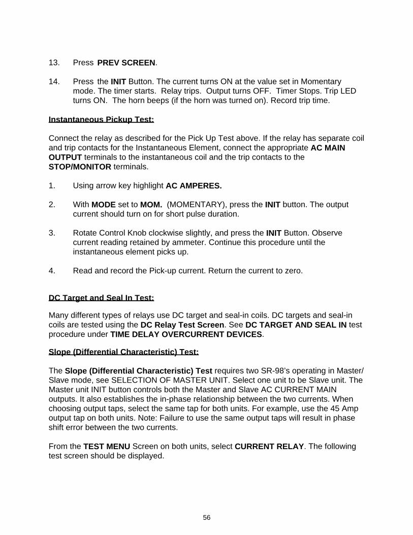
56
13. Press PREV SCREEN. 14. Press the INIT Button. The current turns ON at the value set in Momentary
mode. The timer starts. Relay trips. Output turns OFF. Timer Stops. Trip LED turns ON. The horn beeps (if the horn was turned on). Record trip time.
Instantaneous Pickup Test: Connect the relay as described for the Pick Up Test above. If the relay has separate coil and trip contacts for the Instantaneous Element, connect the appropriate AC MAIN OUTPUT terminals to the instantaneous coil and the trip contacts to the STOP/MONITOR terminals. 1. Using arrow key highlight AC AMPERES. 2. With MODE set to MOM. (MOMENTARY), press the INIT button. The output
current should turn on for short pulse duration. 3. Rotate Control Knob clockwise slightly, and press the INIT Button. Observe
current reading retained by ammeter. Continue this procedure until the instantaneous element picks up.
4. Read and record the Pick-up current. Return the current to zero. DC Target and Seal In Test: Many different types of relays use DC target and seal-in coils. DC targets and seal-in coils are tested using the DC Relay Test Screen. See DC TARGET AND SEAL IN test procedure under TIME DELAY OVERCURRENT DEVICES. Slope (Differential Characteristic) Test: The Slope (Differential Characteristic) Test requires two SR-98’s operating in Master/ Slave mode, see SELECTION OF MASTER UNIT. Select one unit to be Slave unit. The Master unit INIT button controls both the Master and Slave AC CURRENT MAIN outputs. It also establishes the in-phase relationship between the two currents. When choosing output taps, select the same tap for both units. For example, use the 45 Amp output tap on both units. Note: Failure to use the same output taps will result in phase shift error between the two currents. From the TEST MENU Screen on both units, select CURRENT RELAY. The following test screen should be displayed.
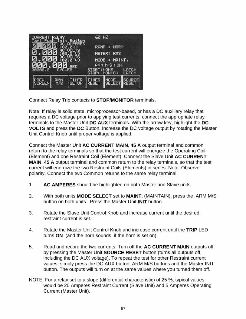
57
Connect Relay Trip contacts to STOP/MONITOR terminals. Note: If relay is solid state, microprocessor-based, or has a DC auxiliary relay that requires a DC voltage prior to applying test currents, connect the appropriate relay terminals to the Master Unit DC AUX terminals. With the arrow key, highlight the DC VOLTS and press the DC Button. Increase the DC voltage output by rotating the Master Unit Control Knob until proper voltage is applied. Connect the Master Unit AC CURRENT MAIN, 45 A output terminal and common return to the relay terminals so that the test current will energize the Operating Coil (Element) and one Restraint Coil (Element). Connect the Slave Unit AC CURRENT MAIN, 45 A output terminal and common return to the relay terminals, so that the test current will energize the two Restraint Coils (Elements) in series. Note: Observe polarity. Connect the two Common returns to the same relay terminal. 1. AC AMPERES should be highlighted on both Master and Slave units. 2. With both units MODE SELECT set to MAINT. (MAINTAIN), press the ARM M/S
button on both units. Press the Master Unit INIT button. 3. Rotate the Slave Unit Control Knob and increase current until the desired
restraint current is set. 4. Rotate the Master Unit Control Knob and increase current until the TRIP LED
turns ON (and the horn sounds, if the horn is set on). 5. Read and record the two currents. Turn off the AC CURRENT MAIN outputs off
by pressing the Master Unit SOURCE RESET button (turns all outputs off, including the DC AUX voltage). To repeat the test for other Restraint current values, simply press the DC AUX button, ARM M/S buttons and the Master INIT button. The outputs will turn on at the same values where you turned them off.
NOTE: For a relay set to a slope (differential characteristic) of 25 %, typical values
would be 20 Amperes Restraint Current (Slave Unit) and 5 Amperes Operating Current (Master Unit).
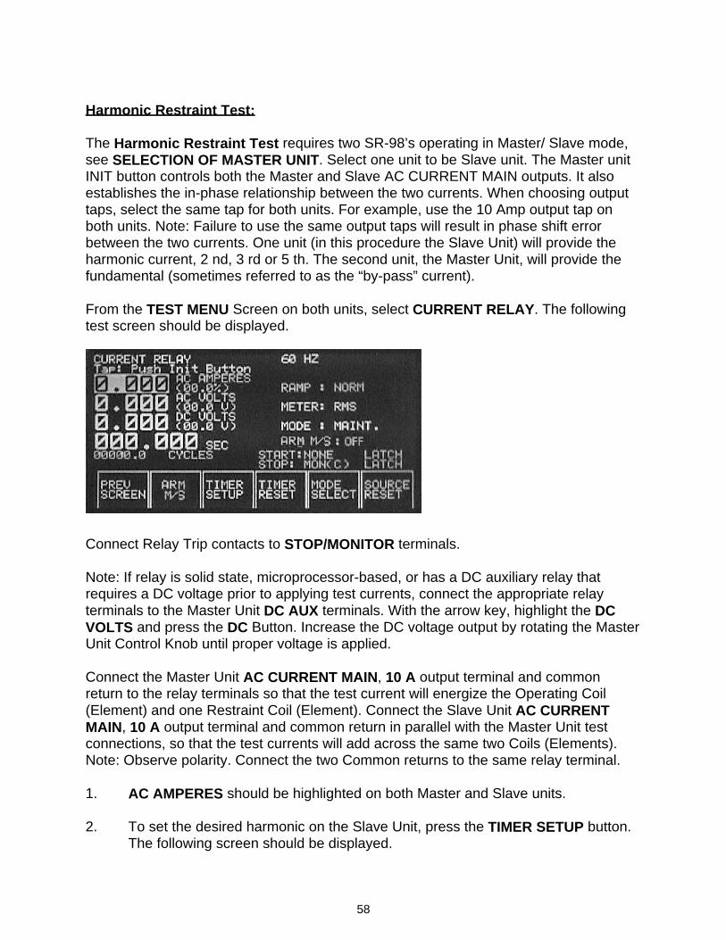
58
Harmonic Restraint Test: The Harmonic Restraint Test requires two SR-98’s operating in Master/ Slave mode, see SELECTION OF MASTER UNIT. Select one unit to be Slave unit. The Master unit INIT button controls both the Master and Slave AC CURRENT MAIN outputs. It also establishes the in-phase relationship between the two currents. When choosing output taps, select the same tap for both units. For example, use the 10 Amp output tap on both units. Note: Failure to use the same output taps will result in phase shift error between the two currents. One unit (in this procedure the Slave Unit) will provide the harmonic current, 2 nd, 3 rd or 5 th. The second unit, the Master Unit, will provide the fundamental (sometimes referred to as the “by-pass” current). From the TEST MENU Screen on both units, select CURRENT RELAY. The following test screen should be displayed.
Connect Relay Trip contacts to STOP/MONITOR terminals. Note: If relay is solid state, microprocessor-based, or has a DC auxiliary relay that requires a DC voltage prior to applying test currents, connect the appropriate relay terminals to the Master Unit DC AUX terminals. With the arrow key, highlight the DC VOLTS and press the DC Button. Increase the DC voltage output by rotating the Master Unit Control Knob until proper voltage is applied. Connect the Master Unit AC CURRENT MAIN, 10 A output terminal and common return to the relay terminals so that the test current will energize the Operating Coil (Element) and one Restraint Coil (Element). Connect the Slave Unit AC CURRENT MAIN, 10 A output terminal and common return in parallel with the Master Unit test connections, so that the test currents will add across the same two Coils (Elements). Note: Observe polarity. Connect the two Common returns to the same relay terminal. 1. AC AMPERES should be highlighted on both Master and Slave units. 2. To set the desired harmonic on the Slave Unit, press the TIMER SETUP button.
The following screen should be displayed.
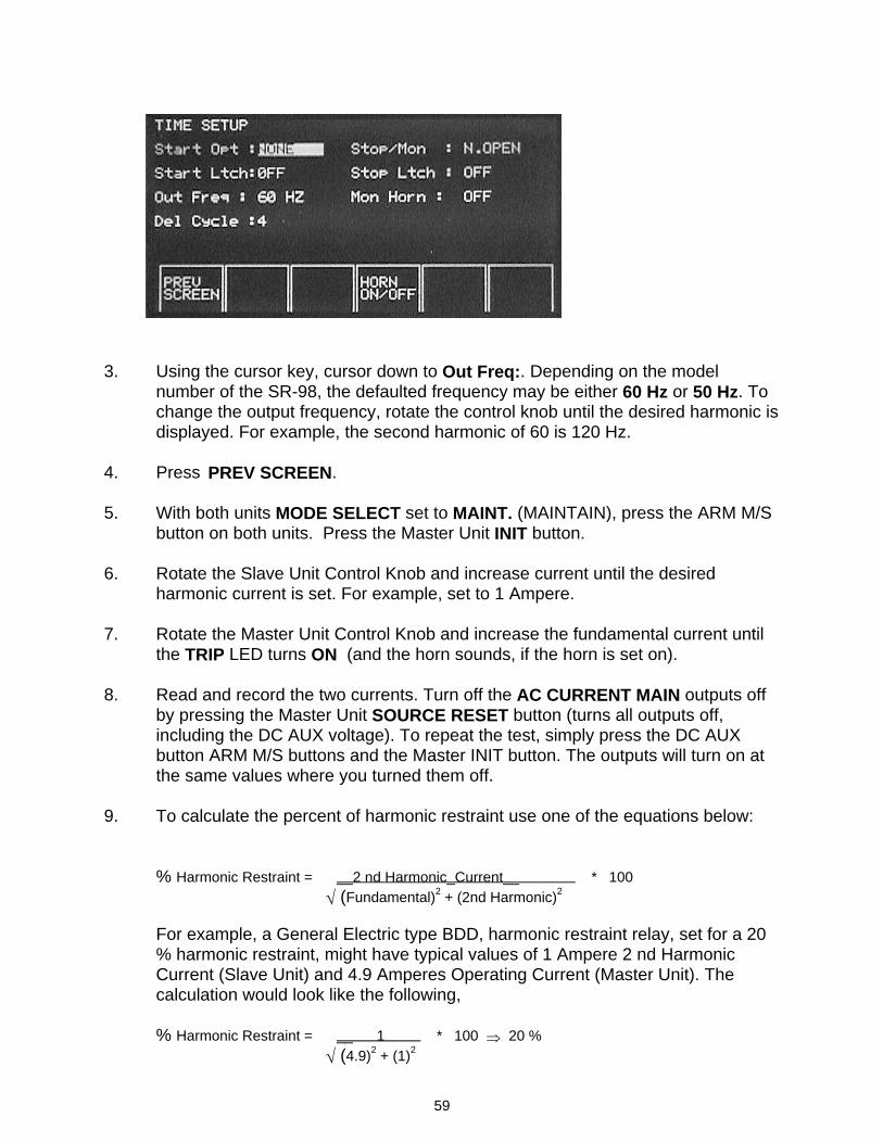
59
3. Using the cursor key, cursor down to Out Freq:. Depending on the model
number of the SR-98, the defaulted frequency may be either 60 Hz or 50 Hz. To change the output frequency, rotate the control knob until the desired harmonic is displayed. For example, the second harmonic of 60 is 120 Hz.
4. Press PREV SCREEN. 5. With both units MODE SELECT set to MAINT. (MAINTAIN), press the ARM M/S
button on both units. Press the Master Unit INIT button. 6. Rotate the Slave Unit Control Knob and increase current until the desired
harmonic current is set. For example, set to 1 Ampere. 7. Rotate the Master Unit Control Knob and increase the fundamental current until
the TRIP LED turns ON (and the horn sounds, if the horn is set on). 8. Read and record the two currents. Turn off the AC CURRENT MAIN outputs off
by pressing the Master Unit SOURCE RESET button (turns all outputs off, including the DC AUX voltage). To repeat the test, simply press the DC AUX button ARM M/S buttons and the Master INIT button. The outputs will turn on at the same values where you turned them off.
9. To calculate the percent of harmonic restraint use one of the equations below:
% Harmonic Restraint = __2 nd Harmonic_Current__ * 100 √ (Fundamental)2 + (2nd Harmonic)2
For example, a General Electric type BDD, harmonic restraint relay, set for a 20 % harmonic restraint, might have typical values of 1 Ampere 2 nd Harmonic Current (Slave Unit) and 4.9 Amperes Operating Current (Master Unit). The calculation would look like the following, % Harmonic Restraint = __ 1 * 100 ⇒ 20 % √ (4.9)2 + (1)2
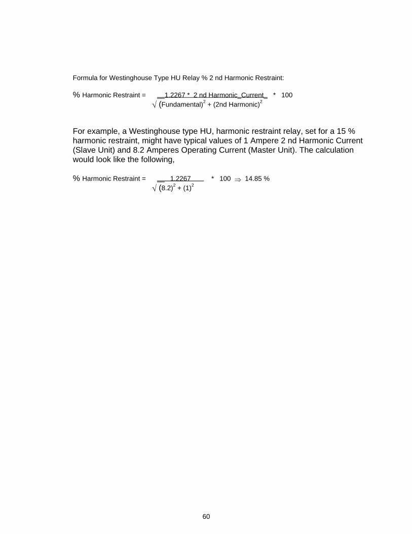
60
Formula for Westinghouse Type HU Relay % 2 nd Harmonic Restraint:
% Harmonic Restraint = __1.2267 * 2 nd Harmonic_Current_ * 100 √ (Fundamental)2 + (2nd Harmonic)2
For example, a Westinghouse type HU, harmonic restraint relay, set for a 15 % harmonic restraint, might have typical values of 1 Ampere 2 nd Harmonic Current (Slave Unit) and 8.2 Amperes Operating Current (Master Unit). The calculation would look like the following, % Harmonic Restraint = __ 1.2267 * 100 ⇒ 14.85 % √ (8.2)2 + (1)2
61
TESTING PHASE SEQUENCE UNDERVOLTAGE RELAYS: This type of relay is tested using the SYNCH RELAY Test Screen. This generic procedure is for a three-phase induction disk relay used to protect ac machines for under-voltage or phase reversal, which may be tested using an open-delta test potential. Similar relays can be tested using the same basic procedure. For relay specific test guides relative to testing these types of relays, see the Megger web site at avointl.com. Click on Products, Relay Test Equipment then on Application Guides.
Type of Tests Pick up High Voltage Contacts Pick up Low Voltage Contacts Timing High Voltage Contacts Timing Low Voltage Contacts Loss of Phase Phase Sequence
Always refer to the manufacturers literature before testing the relay Reverse Phase Voltage Relay: The SYNCH RELAY Test Screen is used to test reverse phase voltage relays, which can be tested using an Open-Delta test potential. This procedure applies to relays that require a balanced three-phase delta voltage. This voltage will be developed using the 230 V / 4 A CURRENT MAIN output terminal, with common, and the AC AUX, 300 V / 0.25 A output terminals. The measured output voltages are labeled (M) for the 230 V CURRENT MAIN and (AUX) for the AC AUX output. The phase angle between the two voltages is displayed as φ Vm lags V, where Vm is the (M) output and the other voltage V is from the AC AUX output. To create an open-delta voltage the AC AUX voltage will be used as the zero reference voltage and the 230 V Main voltage will be phase shifted to an angle of 300 degrees lagging (60 degrees leading the AC AUX voltage). This will appear to the relay as a balanced three-phase delta voltage. From the TEST MENU Screen, select SYNCH RELAY. The following test screen should
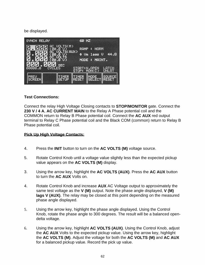
62
be displayed.
Test Connections: Connect the relay High Voltage Closing contacts to STOP/MONITOR gate. Connect the 230 V / 4 A, AC CURRENT MAIN to the Relay A Phase potential coil and the COMMON return to Relay B Phase potential coil. Connect the AC AUX red output terminal to Relay C Phase potential coil and the Black COM (common) return to Relay B Phase potential coil. Pick Up High Voltage Contacts: 4. Press the INIT button to turn on the AC VOLTS (M) voltage source. 5. Rotate Control Knob until a voltage value slightly less than the expected pickup
value appears on the AC VOLTS (M) display. 3. Using the arrow key, highlight the AC VOLTS (AUX). Press the AC AUX button
to turn the AC AUX Volts on. 4. Rotate Control Knob and increase AUX AC Voltage output to approximately the
same test voltage as the V (M) output. Note the phase angle displayed, V (M) lags V (AUX). The relay may be closed at this point depending on the measured phase angle displayed.
5. Using the arrow key, highlight the phase angle displayed. Using the Control
Knob, rotate the phase angle to 300 degrees. The result will be a balanced open-delta voltage.
6. Using the arrow key, highlight AC VOLTS (AUX). Using the Control Knob, adjust
the AC AUX Volts to the expected pickup value. Using the arrow key, highlight the AC VOLTS (M). Adjust the voltage for both the AC VOLTS (M) and AC AUX for a balanced pickup value. Record the pick up value.
63
Phase Sequence Test: With the outputs still on from the High Voltage Contact Pick Up Test, reduce the test voltages to a value that is half way between the high voltage and low voltage pick up values. The moving contact should be “floating” between the two stationary contacts. Using the arrow key, highlight the phase angle displayed (300 degrees). Using the Control Knob, increase the phase angle toward 0 degrees. Note that the moving contact closes toward the Low Voltage Contact. Continue to rotate the control knob, until 30 degrees is indicated. The Low Voltage Contacts should be closed. Return the angle back to 300 degrees, the moving contacts should be “floating” between the High Voltage Contacts and Low Voltage Contacts. Loss of Phase Test: With the outputs still on from the High Voltage Pick Up Test, switch the AC AUX output off by pressing the AC Button. Note that the Low Voltage contacts are closed. Pick Up Low Voltage Contacts: If you have just completed the High Voltage Pick up Test, move the MONITOR leads from the High Voltage Contacts to the Low Voltage contacts, and proceed to step 5. Otherwise, connect the Low Voltage contacts, see Test Connections above, and proceed to Step 1. 1. Press the INIT button to turn on the AC VOLTS (M) voltage source. Rotate
Control Knob until a voltage value slightly more than the expected pickup value appears on the AC VOLTS (M) display.
2. Using the arrow key, highlight the AC VOLTS (AUX). Press the AC AUX button
to turn the AC AUX Volts on.
3. Rotate Control Knob and increase AUX AC Voltage output to approximately the same test voltage as the V (M) output. Note the phase angle displayed, V (M) lags V (AUX). The relay may be closed at this point depending on the measured phase angle displayed.
4. Using the arrow key, highlight the phase angle displayed. Using the Control
Knob, rotate the phase angle to 300 degrees.
5. Using the arrow key, highlight AC VOLTS (AUX). Using the Control Knob, adjust the AC AUX Volts to the expected pickup value. Using the arrow key, highlight the AC VOLTS (M). Adjust the voltage for both the AC VOLTS (M) and AC AUX for a balanced pickup value. Record the pick up value.
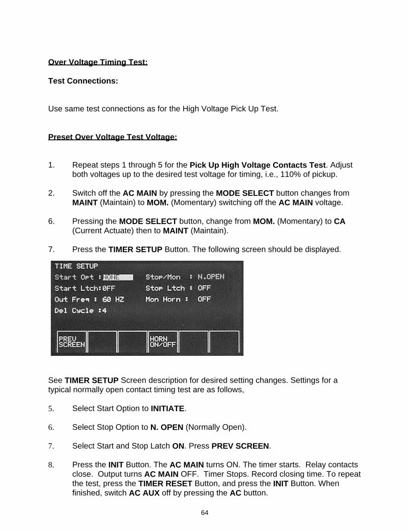
64
Over Voltage Timing Test: Test Connections: Use same test connections as for the High Voltage Pick Up Test. Preset Over Voltage Test Voltage: 1. Repeat steps 1 through 5 for the Pick Up High Voltage Contacts Test. Adjust
both voltages up to the desired test voltage for timing, i.e., 110% of pickup. 2. Switch off the AC MAIN by pressing the MODE SELECT button changes from
MAINT (Maintain) to MOM. (Momentary) switching off the AC MAIN voltage. 6. Pressing the MODE SELECT button, change from MOM. (Momentary) to CA
(Current Actuate) then to MAINT (Maintain). 7. Press the TIMER SETUP Button. The following screen should be displayed.
See TIMER SETUP Screen description for desired setting changes. Settings for a typical normally open contact timing test are as follows, 5. Select Start Option to INITIATE. 6. Select Stop Option to N. OPEN (Normally Open). 7. Select Start and Stop Latch ON. Press PREV SCREEN. 8. Press the INIT Button. The AC MAIN turns ON. The timer starts. Relay contacts
close. Output turns AC MAIN OFF. Timer Stops. Record closing time. To repeat the test, press the TIMER RESET Button, and press the INIT Button. When finished, switch AC AUX off by pressing the AC button.
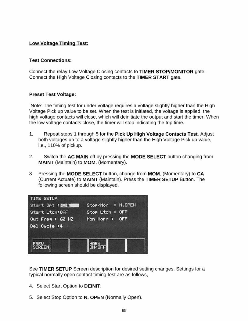
65
Low Voltage Timing Test: Test Connections: Connect the relay Low Voltage Closing contacts to TIMER STOP/MONITOR gate. Connect the High Voltage Closing contacts to the TIMER START gate. Preset Test Voltage: Note: The timing test for under voltage requires a voltage slightly higher than the High Voltage Pick up value to be set. When the test is initiated, the voltage is applied, the high voltage contacts will close, which will deinitiate the output and start the timer. When the low voltage contacts close, the timer will stop indicating the trip time. 1. Repeat steps 1 through 5 for the Pick Up High Voltage Contacts Test. Adjust
both voltages up to a voltage slightly higher than the High Voltage Pick up value, i.e., 110% of pickup.
2. Switch the AC MAIN off by pressing the MODE SELECT button changing from
MAINT (Maintain) to MOM. (Momentary). 3. Pressing the MODE SELECT button, change from MOM. (Momentary) to CA
(Current Actuate) to MAINT (Maintain). Press the TIMER SETUP Button. The following screen should be displayed.
See TIMER SETUP Screen description for desired setting changes. Settings for a typical normally open contact timing test are as follows, 4. Select Start Option to DEINIT. 5. Select Stop Option to N. OPEN (Normally Open).
66
6. Select Start and Stop Latch ON. Press PREV SCREEN. 7. Press the TIMER RESET Button. Press the INIT Button. The AC MAIN turns ON.
When the High Voltage contacts close, AC MAIN output turns OFF, and the timer starts. When the Low Voltage contacts close the Timer Stops. Record the Low Voltage Closing Time. To repeat the test, press the TIMER RESET Button, and press the INIT Button. When the test is completed, turn the AC AUX Off.
MOLDED CASE CIRCUIT BREAKERS Always refer to the manufacturer's literature applicable to the particular circuit breaker before testing. The test operator should be familiar with the operating characteristics of the circuit breaker, the tolerances applicable to the operating characteristics and the means for adjusting the circuit breaker, if any. The test usually performed on these devices is to verify the time delay characteristics of the circuit breaker when subjected to an overload. Each pole of the circuit breaker should be tested independently. One test point is usually suggested to establish whether the circuit breaker is operating correctly and within the band of the time-current curve for the circuit breaker. The suggested test current is three times (3X) the normal current rating of the circuit breaker. It is, of course, easiest to make connections and perform the test on circuit breakers if they are removed from the circuit. However, it is not necessary to remove the circuit breaker, as long as the test leads can be connected and the line side of the breaker de-energized. It should be further noted that any leads already connected to the circuit breaker need not be removed when conducting the test. The high-current leads from the test set to the circuit breaker under test should be kept as short as possible and should be twisted to minimize the losses caused by inductive reactance. Run the test and note the time required for the circuit breaker to trip. If the tripping time exceeds the desired value or if the circuit breaker does not trip at all, the circuit breaker may not be protecting the circuit properly. If the circuit breaker operates too quickly, it may result in unnecessary nuisance trips. It should be remembered that molded case circuit breakers operate within a wide time band. Therefore, precise results should not be sought and, if the circuit breaker trips within the time band, it is considered satisfactory. A tolerance of ±15% is usually acceptable. Look for the circuit breaker that has unusually short time delay or takes an abnormally long time to trip or does not trip at all. In the latter case, electrically operating, and thereby exercising the breaker, may correct the condition.
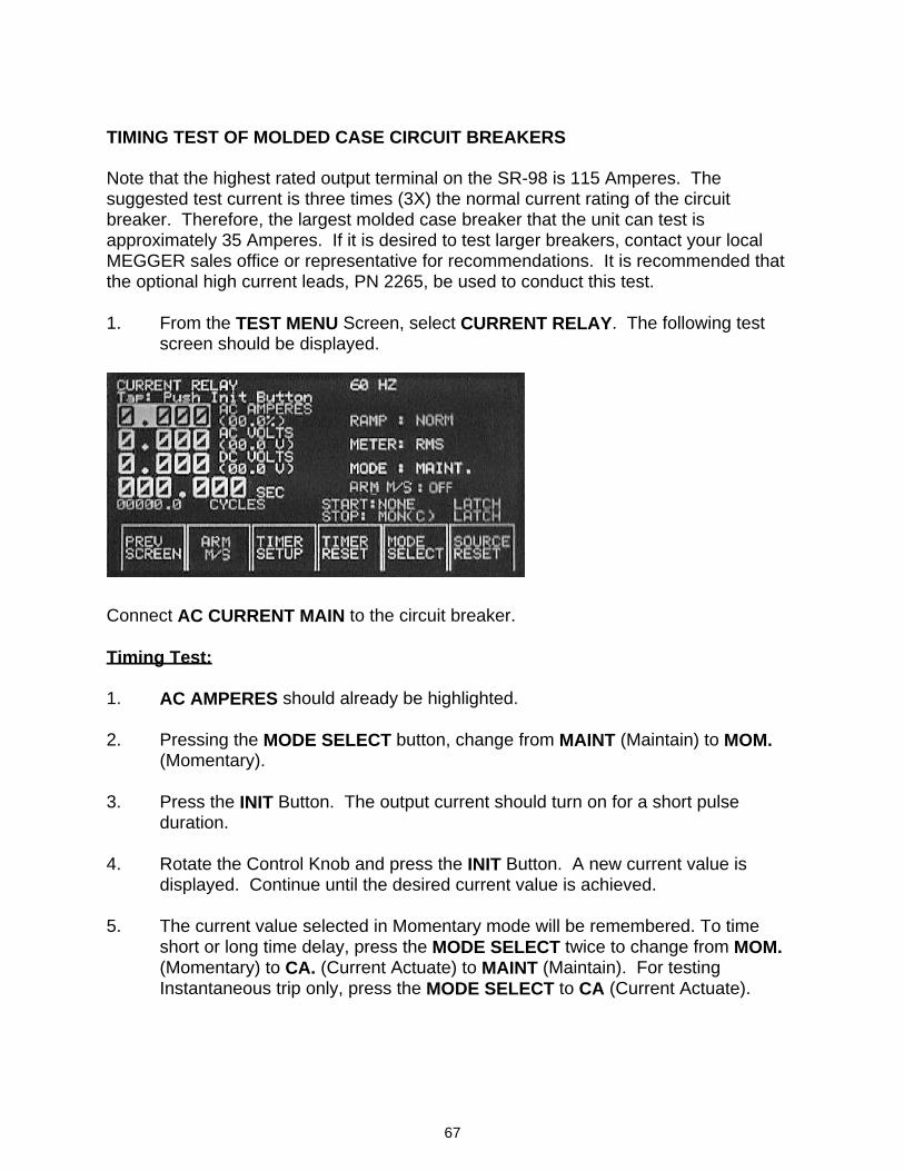
67
TIMING TEST OF MOLDED CASE CIRCUIT BREAKERS Note that the highest rated output terminal on the SR-98 is 115 Amperes. The suggested test current is three times (3X) the normal current rating of the circuit breaker. Therefore, the largest molded case breaker that the unit can test is approximately 35 Amperes. If it is desired to test larger breakers, contact your local MEGGER sales office or representative for recommendations. It is recommended that the optional high current leads, PN 2265, be used to conduct this test. 1. From the TEST MENU Screen, select CURRENT RELAY. The following test
screen should be displayed.
Connect AC CURRENT MAIN to the circuit breaker. Timing Test: 1. AC AMPERES should already be highlighted. 2. Pressing the MODE SELECT button, change from MAINT (Maintain) to MOM.
(Momentary). 3. Press the INIT Button. The output current should turn on for a short pulse
duration. 4. Rotate the Control Knob and press the INIT Button. A new current value is
displayed. Continue until the desired current value is achieved. 5. The current value selected in Momentary mode will be remembered. To time
short or long time delay, press the MODE SELECT twice to change from MOM. (Momentary) to CA. (Current Actuate) to MAINT (Maintain). For testing Instantaneous trip only, press the MODE SELECT to CA (Current Actuate).
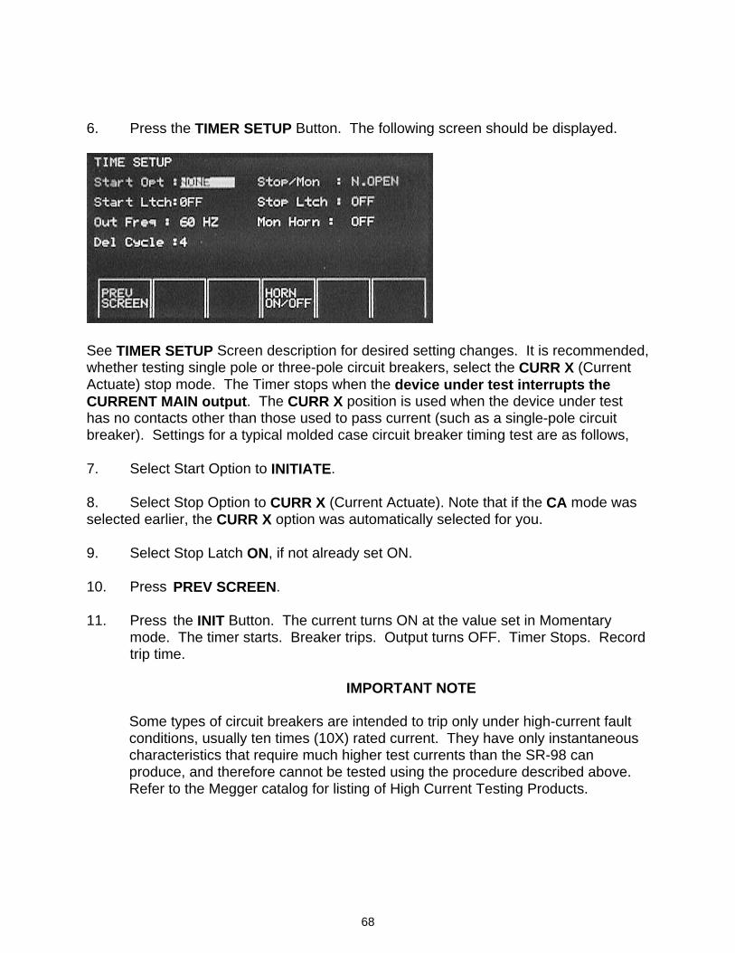
68
6. Press the TIMER SETUP Button. The following screen should be displayed.
See TIMER SETUP Screen description for desired setting changes. It is recommended, whether testing single pole or three-pole circuit breakers, select the CURR X (Current Actuate) stop mode. The Timer stops when the device under test interrupts the CURRENT MAIN output. The CURR X position is used when the device under test has no contacts other than those used to pass current (such as a single-pole circuit breaker). Settings for a typical molded case circuit breaker timing test are as follows, 7. Select Start Option to INITIATE. 8. Select Stop Option to CURR X (Current Actuate). Note that if the CA mode was selected earlier, the CURR X option was automatically selected for you. 9. Select Stop Latch ON, if not already set ON. 10. Press PREV SCREEN. 11. Press the INIT Button. The current turns ON at the value set in Momentary
mode. The timer starts. Breaker trips. Output turns OFF. Timer Stops. Record trip time.
IMPORTANT NOTE Some types of circuit breakers are intended to trip only under high-current fault
conditions, usually ten times (10X) rated current. They have only instantaneous characteristics that require much higher test currents than the SR-98 can produce, and therefore cannot be tested using the procedure described above. Refer to the Megger catalog for listing of High Current Testing Products.
69
MOTOR OVERLOAD RELAYS Always refer to the manufacturer's literature applicable to the particular overload relay before testing. The test operator should be familiar with the operating characteristics of the relay, the tolerances applicable to the operating characteristics and the means of adjusting the relay, if any. The test usually performed on these devices is to verify the time delay characteristics of the relay when subjected to an overload. One test point is usually suggested to establish whether the relay is operating correctly and within the band of the time-current curve for relay. The suggested test current is three times (3X) the normal current-rating of thermal overload relays or three times (3X) the pick-up current (setting) of magnetic overload relays. It is, of course, easiest to make the connections and perform the tests on the relays if they are removed from the starter. However, it is not necessary to remove the relay as long as the test leads can be connected and the circuit de-energized. It should be further noted that any leads already connected to the relay need not be removed when conducting the tests. It is recommended that the optional high current leads, PN 2265, be used to conduct this test. The high-current leads from the test set to the relay under test should be kept as short as possible and should be twisted to minimize the losses caused by inductive reactance. Run the test (see TESTING TIME DELAY OVERCURRENT DEVICES) and note the time required for the overload relay to trip. If the tripping time exceeds the desired value, or if the relay does not trip at all, the relay may not be protecting the motor properly. If the relay operates too quickly, it may result in unnecessary nuisance trips. It should be remembered that these devices operate over a wide band and precise results should not be sought. A tolerance of ±15% is usually acceptable. If a thermal overload relay is not operating properly, tripping too soon or too late, remove the heater element. Note its type, rating, etc., and compare with manufacturer's data for operating characteristics of the motor. If correct for the application, substitute a new heater of the same rating and retest. If improper heater elements are being used, either under or oversized, replace with the proper sized heater and retest. If a magnetic overload relay is not operating properly, refer to the relay manufacturer's literature for instructions on making adjustments to the time delay. If the relay is operating improperly, it may also be desirable to verify the pick-up point (minimum operating point) of the relay. To perform this test, it is necessary to disengage the time delay feature of the overload relay. Refer to the manufacturer's literature for detailed instructions.
70
PARALLEL PRINTER PORT The printer port is located on the lower left-hand side of the unit, and uses a 25 -pin delta connector. To send data to the printer port, from any test screen simply push the PRINT SCRN (SCREEN) Button. The metered and/or calculated data on the screen will be printed similar to the screen presentation. Dot Matrix Printer Pin-Out PIN NUMBER DESCRIPTION FUNCTION 1 STROBE OUTPUT 2 DATA BIT 0 OUTPUT 3 DATA BIT 1 OUTPUT 4 DATA BIT 2 OUTPUT 5 DATA BIT 3 OUTPUT 6 DATA BIT 4 OUTPUT 7 DATA BIT 5 OUTPUT 8 DATA BIT 6 OUTPUT 9 DATA BIT 7 (MSB) OUTPUT 10 ACKNOWLEDGE INPUT 11 BUSY INPUT 19 – 25 SIGNAL GROUND ----- Other pins are not used. RS232 SERIAL DATA PORT The serial data port is located on the lower left front corner of the unit. It uses a 9-pin delta connector. A standard 9-pin male/female cable must be used to connect the unit to a computer. The serial port can be directly connected to a terminal, a compatible serial data acquisition system or a COM port on any personal computer. Commonly used communication programs like ProComm or Windows Terminal or Hyper Terminal can be used to collect data from the unit. The required cable is not null-modem.
71
Communications Port Settings Baud Rate: 19,200 Data Bits: 8 Parity: None Stop Bits: 1 Flow Control: None The pin-out from the 9-pin connector is shown below. Note that data transmission is unidirectional. RS232 Connection Pin-Out PIN NUMBER DESCRIPTION FUNCTION 2 TxD Transmit Data 3 RxD Receive Data 5 GND Signal Ground 7 CTS Send To Clear 8 RTS Request To Send Other pins are not used. SR-98 COMMAND SET The SR-98 incorporates an RS232 Serial Data Communications Port for communicating with a personal computer. This feature may be used to transmit data from the SR-98 to the computer for data analysis and report generation. The SR-98 can be programmed to change Menu Screens, Select a language, Setup the timer or Specify a relay to test, and Query the test set for metered or calculated values. See the following commands. All commands must end with a semi-colon ; Screen Command Power Up spu; Test Menu st; About sa; Language Select sls; Select, Setup or Specify commands are used to select different options from each of the menu screens. For example, the Language Selection Screen has the following selections; English, French, Spanish, German, Portuguese and Japanese. The operator should be able to select any one of the selectable languages. The following commands apply.
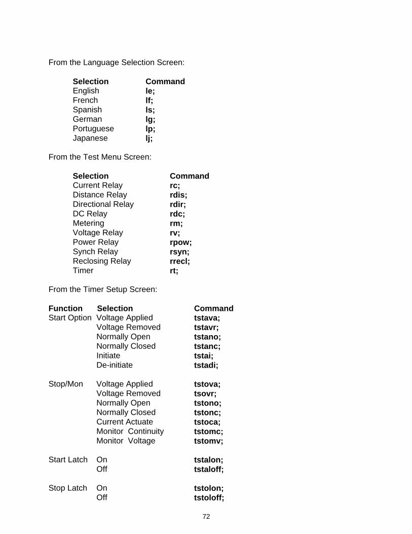
72
From the Language Selection Screen: Selection Command English le; French lf; Spanish ls; German lg; Portuguese lp; Japanese lj; From the Test Menu Screen: Selection Command Current Relay rc; Distance Relay rdis; Directional Relay rdir; DC Relay rdc; Metering rm; Voltage Relay rv; Power Relay rpow; Synch Relay rsyn; Reclosing Relay rrecl; Timer rt; From the Timer Setup Screen: Function Selection Command Start Option Voltage Applied tstava; Voltage Removed tstavr; Normally Open tstano; Normally Closed tstanc; Initiate tstai; De-initiate tstadi; Stop/Mon Voltage Applied tstova; Voltage Removed tsovr; Normally Open tstono; Normally Closed tstonc; Current Actuate tstoca; Monitor Continuity tstomc; Monitor Voltage tstomv; Start Latch On tstalon; Off tstaloff; Stop Latch On tstolon; Off tstoloff;
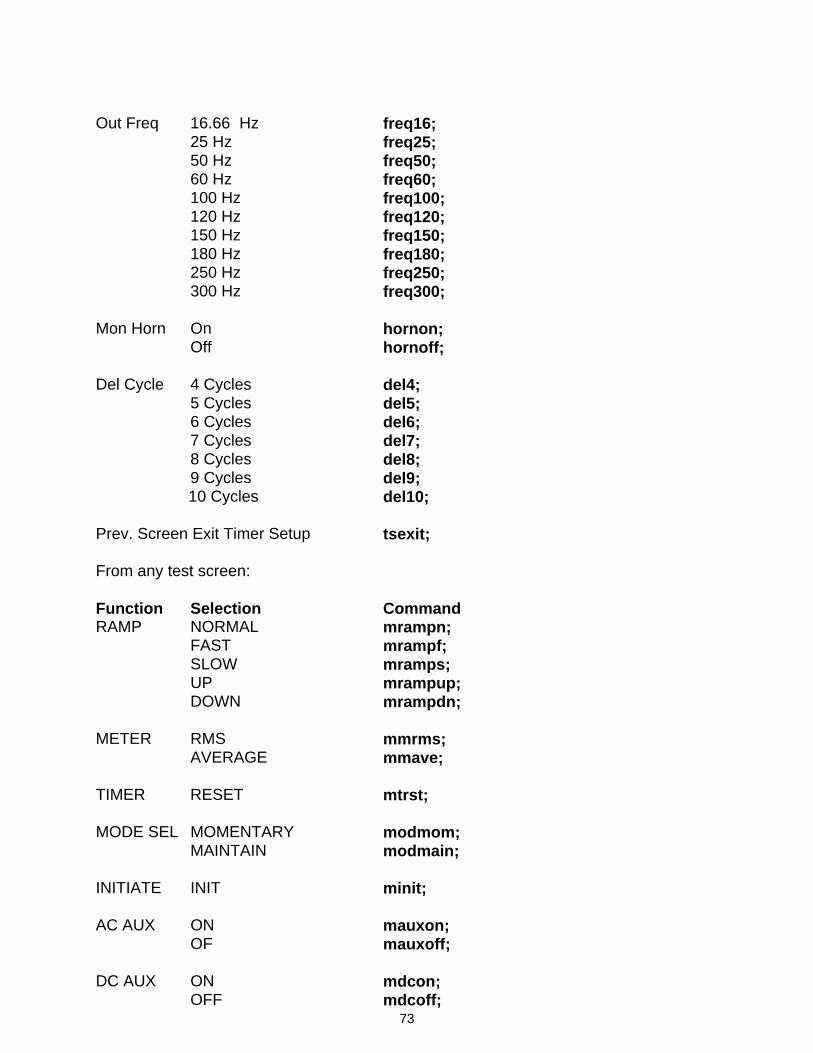
73
Out Freq 16.66 Hz freq16; 25 Hz freq25; 50 Hz freq50; 60 Hz freq60; 100 Hz freq100; 120 Hz freq120; 150 Hz freq150; 180 Hz freq180; 250 Hz freq250; 300 Hz freq300; Mon Horn On hornon; Off hornoff; Del Cycle 4 Cycles del4; 5 Cycles del5; 6 Cycles del6; 7 Cycles del7; 8 Cycles del8; 9 Cycles del9; 10 Cycles del10; Prev. Screen Exit Timer Setup tsexit; From any test screen: Function Selection Command RAMP NORMAL mrampn; FAST mrampf; SLOW mramps; UP mrampup; DOWN mrampdn; METER RMS mmrms; AVERAGE mmave; TIMER RESET mtrst; MODE SEL MOMENTARY modmom; MAINTAIN modmain; INITIATE INIT minit; AC AUX ON mauxon; OF mauxoff; DC AUX ON mdcon; OFF mdcoff;
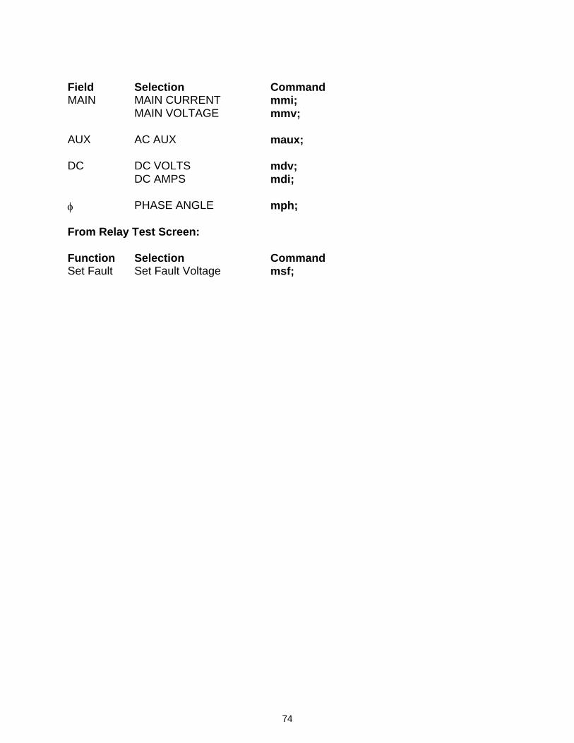
74
Field Selection Command MAIN MAIN CURRENT mmi; MAIN VOLTAGE mmv; AUX AC AUX maux; DC DC VOLTS mdv; DC AMPS mdi; φ PHASE ANGLE mph; From Relay Test Screen: Function Selection Command Set Fault Set Fault Voltage msf;
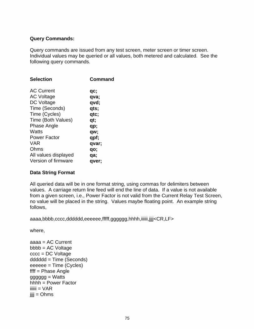
75
Query Commands: Query commands are issued from any test screen, meter screen or timer screen. Individual values may be queried or all values, both metered and calculated. See the following query commands. Selection Command AC Current qc; AC Voltage qva; DC Voltage qvd; Time (Seconds) qts; Time (Cycles) qtc; Time (Both Values) qt; Phase Angle qp; Watts qw; Power Factor qpf; VAR qvar; Ohms qo; All values displayed qa; Version of firmware qver; Data String Format All queried data will be in one format string, using commas for delimiters between values. A carriage return line feed will end the line of data. If a value is not available from a given screen, i.e., Power Factor is not valid from the Current Relay Test Screen, no value will be placed in the string. Values maybe floating point. An example string follows, aaaa,bbbb,cccc,dddddd,eeeeee,fffff,gggggg,hhhh,iiiiii,jjjj<CR,LF> where, aaaa = AC Current bbbb = AC Voltage cccc = DC Voltage dddddd = Time (Seconds) eeeeee = Time (Cycles) ffff = Phase Angle gggggg = Watts hhhh = Power Factor iiiiii = VAR jjjj = Ohms
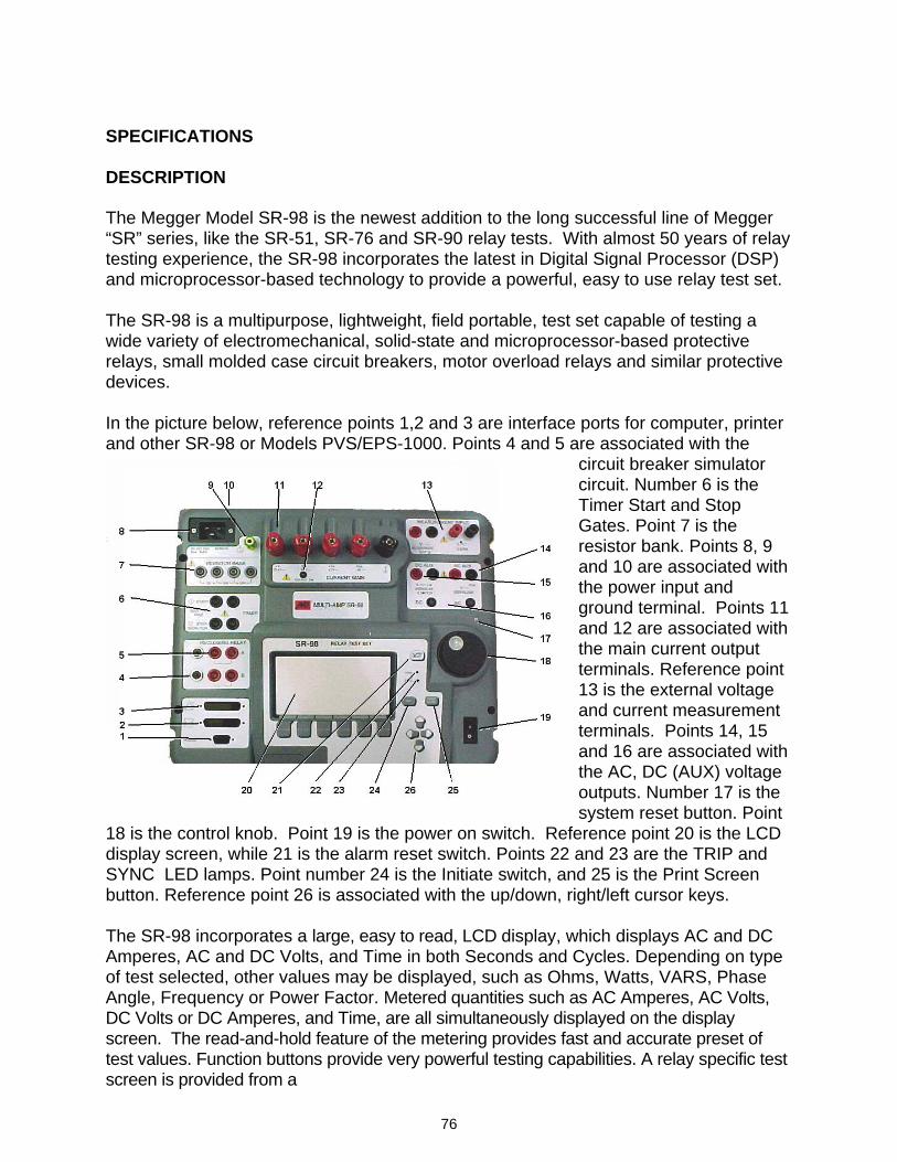
76
SPECIFICATIONS DESCRIPTION The Megger Model SR-98 is the newest addition to the long successful line of Megger “SR” series, like the SR-51, SR-76 and SR-90 relay tests. With almost 50 years of relay testing experience, the SR-98 incorporates the latest in Digital Signal Processor (DSP) and microprocessor-based technology to provide a powerful, easy to use relay test set. The SR-98 is a multipurpose, lightweight, field portable, test set capable of testing a wide variety of electromechanical, solid-state and microprocessor-based protective relays, small molded case circuit breakers, motor overload relays and similar protective devices. In the picture below, reference points 1,2 and 3 are interface ports for computer, printer and other SR-98 or Models PVS/EPS-1000. Points 4 and 5 are associated with the
circuit breaker simulator circuit. Number 6 is the Timer Start and Stop Gates. Point 7 is the resistor bank. Points 8, 9 and 10 are associated with the power input and ground terminal. Points 11 and 12 are associated with the main current output terminals. Reference point 13 is the external voltage and current measurement terminals. Points 14, 15 and 16 are associated with the AC, DC (AUX) voltage outputs. Number 17 is the system reset button. Point
18 is the control knob. Point 19 is the power on switch. Reference point 20 is the LCD display screen, while 21 is the alarm reset switch. Points 22 and 23 are the TRIP and SYNC LED lamps. Point number 24 is the Initiate switch, and 25 is the Print Screen button. Reference point 26 is associated with the up/down, right/left cursor keys. The SR-98 incorporates a large, easy to read, LCD display, which displays AC and DC Amperes, AC and DC Volts, and Time in both Seconds and Cycles. Depending on type of test selected, other values may be displayed, such as Ohms, Watts, VARS, Phase Angle, Frequency or Power Factor. Metered quantities such as AC Amperes, AC Volts, DC Volts or DC Amperes, and Time, are all simultaneously displayed on the display screen. The read-and-hold feature of the metering provides fast and accurate preset of test values. Function buttons provide very powerful testing capabilities. A relay specific test screen is provided from a
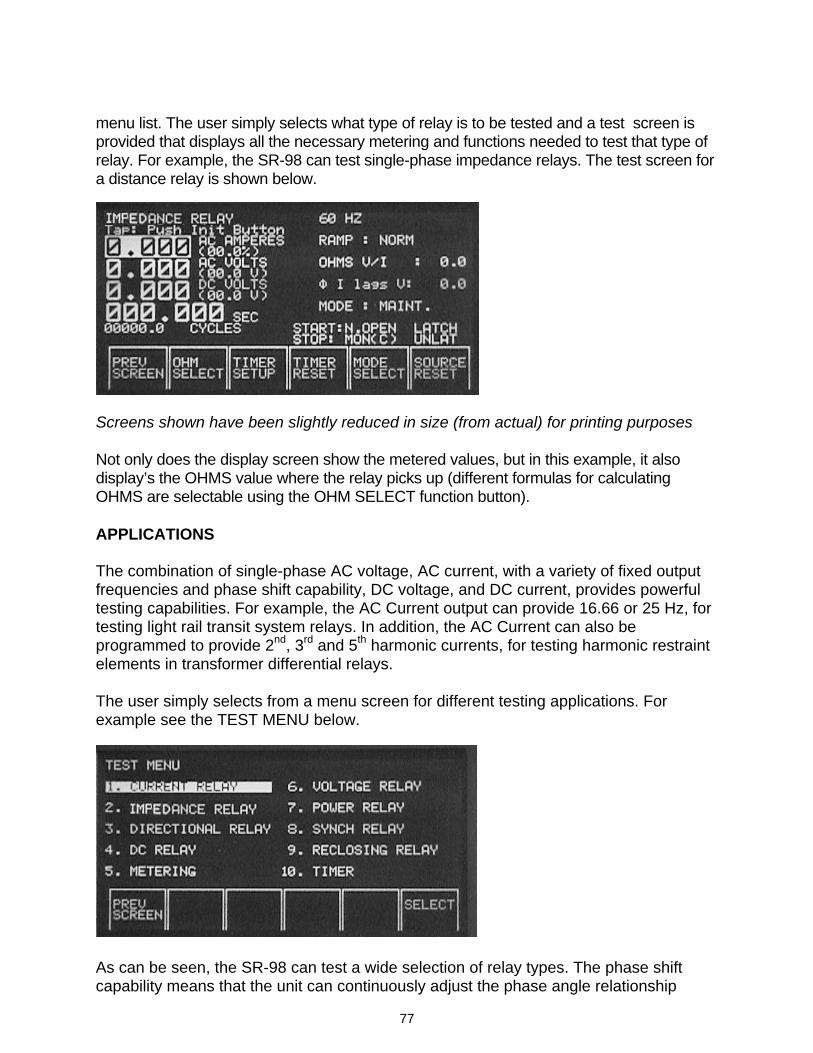
77
menu list. The user simply selects what type of relay is to be tested and a test screen is provided that displays all the necessary metering and functions needed to test that type of relay. For example, the SR-98 can test single-phase impedance relays. The test screen for a distance relay is shown below.
Screens shown have been slightly reduced in size (from actual) for printing purposes Not only does the display screen show the metered values, but in this example, it also display’s the OHMS value where the relay picks up (different formulas for calculating OHMS are selectable using the OHM SELECT function button). APPLICATIONS The combination of single-phase AC voltage, AC current, with a variety of fixed output frequencies and phase shift capability, DC voltage, and DC current, provides powerful testing capabilities. For example, the AC Current output can provide 16.66 or 25 Hz, for testing light rail transit system relays. In addition, the AC Current can also be programmed to provide 2nd, 3rd and 5th harmonic currents, for testing harmonic restraint elements in transformer differential relays. The user simply selects from a menu screen for different testing applications. For example see the TEST MENU below.
As can be seen, the SR-98 can test a wide selection of relay types. The phase shift capability means that the unit can continuously adjust the phase angle relationship
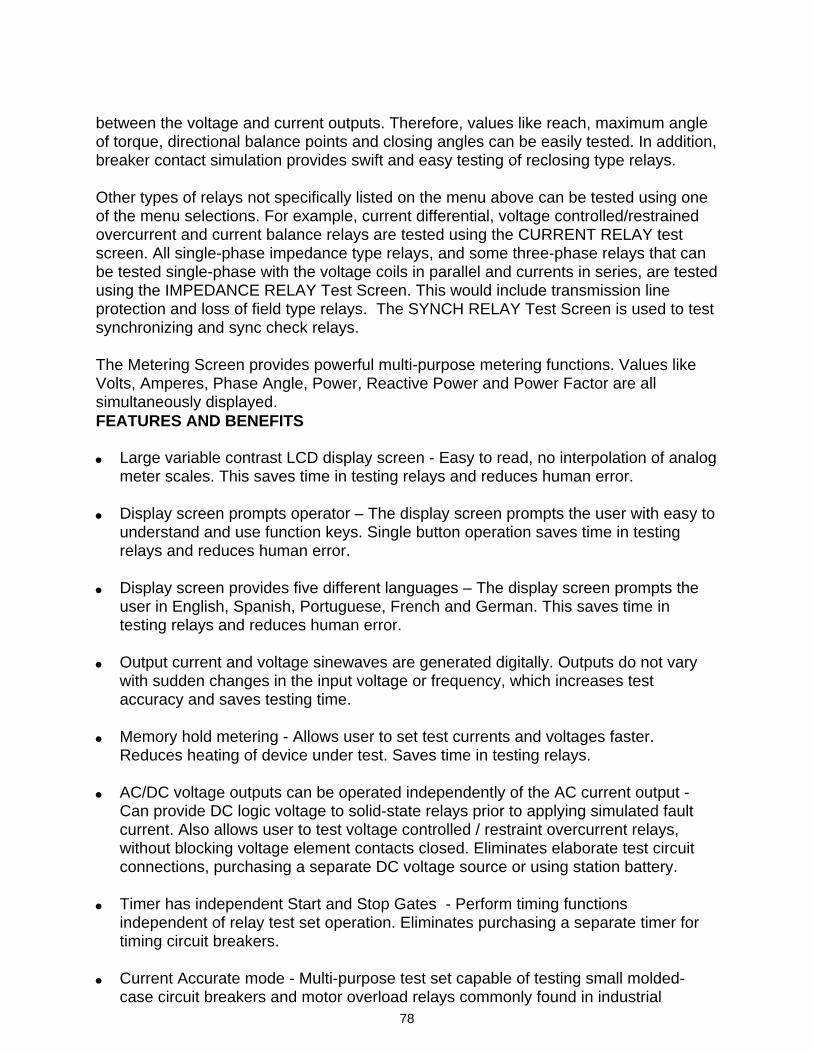
78
between the voltage and current outputs. Therefore, values like reach, maximum angle of torque, directional balance points and closing angles can be easily tested. In addition, breaker contact simulation provides swift and easy testing of reclosing type relays. Other types of relays not specifically listed on the menu above can be tested using one of the menu selections. For example, current differential, voltage controlled/restrained overcurrent and current balance relays are tested using the CURRENT RELAY test screen. All single-phase impedance type relays, and some three-phase relays that can be tested single-phase with the voltage coils in parallel and currents in series, are tested using the IMPEDANCE RELAY Test Screen. This would include transmission line protection and loss of field type relays. The SYNCH RELAY Test Screen is used to test synchronizing and sync check relays. The Metering Screen provides powerful multi-purpose metering functions. Values like Volts, Amperes, Phase Angle, Power, Reactive Power and Power Factor are all simultaneously displayed. FEATURES AND BENEFITS • Large variable contrast LCD display screen - Easy to read, no interpolation of analog
meter scales. This saves time in testing relays and reduces human error. • Display screen prompts operator – The display screen prompts the user with easy to
understand and use function keys. Single button operation saves time in testing relays and reduces human error.
• Display screen provides five different languages – The display screen prompts the
user in English, Spanish, Portuguese, French and German. This saves time in testing relays and reduces human error.
• Output current and voltage sinewaves are generated digitally. Outputs do not vary
with sudden changes in the input voltage or frequency, which increases test accuracy and saves testing time.
• Memory hold metering - Allows user to set test currents and voltages faster.
Reduces heating of device under test. Saves time in testing relays. • AC/DC voltage outputs can be operated independently of the AC current output -
Can provide DC logic voltage to solid-state relays prior to applying simulated fault current. Also allows user to test voltage controlled / restraint overcurrent relays, without blocking voltage element contacts closed. Eliminates elaborate test circuit connections, purchasing a separate DC voltage source or using station battery.
• Timer has independent Start and Stop Gates - Perform timing functions
independent of relay test set operation. Eliminates purchasing a separate timer for timing circuit breakers.
• Current Accurate mode - Multi-purpose test set capable of testing small molded-
case circuit breakers and motor overload relays commonly found in industrial
79
applications. • Interface port - Provides interface to other SR-98’s or MEGGER Phase Shifters.
Allows SR-98 unit to be used with another SR-98 to test slope and harmonic restraint characteristics on current differential relays. Allows SR-98 unit to be used with a three-phase phase shifter to test complex three-phase relays. Saves time in making test connections. Multi-purpose test system saves money.
• Phase shift capability (0 to 359.9°) - The SR-98 provides phase shift between the
main ac current and auxiliary ac voltage outputs (for testing complex relays), or between the 230 volt output terminal of the main ac current and the auxiliary ac voltage outputs (for testing synchronizing and phase sequence relays).
• Selectable output frequencies - The output frequency of the ac main current can be
set for 16.66, 25 Hz (for testing light rail transit relays), 50, 60 Hz (standard power frequency), 100, 120, 150, 180, 250 and 300 Hz (for testing harmonic restraint on transformer differential relays). Multi-purpose test system saves time and money.
• Circuit breaker simulator – Normally closed and normally open contacts are provided
to simulate breaker operation for testing reclosing relays. Sequence of operation, timing and lockout are easily tested.
• Non-volatile RAM – Provides storage of special test set-up screens. • RS-232 and parallel printer ports – The RS-232 port provides for computer interface.
The parallel printer port allows user to easily print test results. • Universal input voltage – Models SR-98-1 and SR-98-2 can use virtually any
standard source in the world. The Model SR-98-3 is designed for 230 Volt operation only.
APPLICATIONS The combination of single-phase AC voltage, AC current, with a variety of fixed output frequencies and phase shift capability, DC voltage, and DC current, provides powerful testing capabilities. For example, the AC Current output can provide 16.66 or 25 Hz, for testing transit system relays. In addition, the AC Current can also be programmed to provide 2nd, 3rd and 5th harmonic currents, for testing harmonic restraint elements in transformer differential relays.
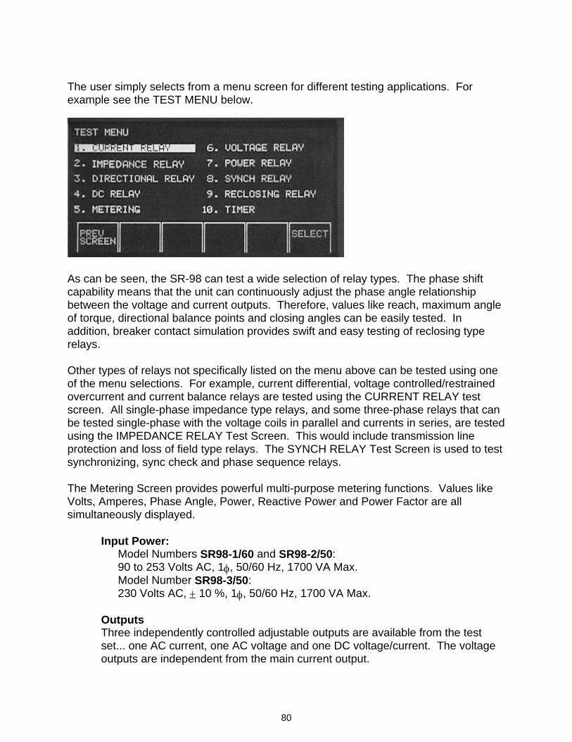
80
The user simply selects from a menu screen for different testing applications. For example see the TEST MENU below.
As can be seen, the SR-98 can test a wide selection of relay types. The phase shift capability means that the unit can continuously adjust the phase angle relationship between the voltage and current outputs. Therefore, values like reach, maximum angle of torque, directional balance points and closing angles can be easily tested. In addition, breaker contact simulation provides swift and easy testing of reclosing type relays. Other types of relays not specifically listed on the menu above can be tested using one of the menu selections. For example, current differential, voltage controlled/restrained overcurrent and current balance relays are tested using the CURRENT RELAY test screen. All single-phase impedance type relays, and some three-phase relays that can be tested single-phase with the voltage coils in parallel and currents in series, are tested using the IMPEDANCE RELAY Test Screen. This would include transmission line protection and loss of field type relays. The SYNCH RELAY Test Screen is used to test synchronizing, sync check and phase sequence relays. The Metering Screen provides powerful multi-purpose metering functions. Values like Volts, Amperes, Phase Angle, Power, Reactive Power and Power Factor are all simultaneously displayed. Input Power: Model Numbers SR98-1/60 and SR98-2/50:
90 to 253 Volts AC, 1φ, 50/60 Hz, 1700 VA Max. Model Number SR98-3/50: 230 Volts AC, ± 10 %, 1φ, 50/60 Hz, 1700 VA Max.
Outputs Three independently controlled adjustable outputs are available from the test set... one AC current, one AC voltage and one DC voltage/current. The voltage outputs are independent from the main current output.
81
AC Main Output Current The main AC current output is rated for 920 VA, with four different output terminals continuously adjustable in the following ranges: Output Current Full Load Voltage
0 - 4 Amperes 230 Volts 0 - 10 Amperes 90 Volts 0 - 45 Amperes 20 Volts 0 - 115 Amperes 8 Volts
Output current is de-rated at output frequencies less than 50 Hz and greater than 120 Hz. For example, the available output current is less than 50 % of rated tap value at 25 Hz, and less than 20 % at 16.6 Hz. Percentage varies depending on the selected output tap, the test frequency and the load. For example, at the selected output frequency of 180 Hz, you can get 110 Amperes at 7.7 Volts from the 115 Amp output tap, while at 300 Hz you get less than 95 Amperes at 6.7 Volts into the same load. For more information contact the factory. Output Current Duty Cycle Maximum time on is 3 minutes followed by 20 minutes off. Duty is reduced to 1 minute on and 20 minutes off at ambient temperature of 122°F (50°C). AC Voltage Output The AC voltage output is independently controlled and may be phase shifted relative to the Main AC Current/Voltage outputs. Output Voltage Current Rating 0 - 230 Volts 4 Amp (AC CURRENT MAIN) 0 - 300 Volts 0.25 Amp (AC AUX)
DC Voltage/Current Output (Switch Selected) Output Voltage Current Rating 0 - 240 Volts 0.4 Amp
Output Current Voltage Rating 0 – 2.5 Amps 12 Volts
82
AC/DC Output Voltage Duty Cycle 30 Minutes on followed by 30 minutes off. Metering Measured quantities such as AC Amperes, AC Volts, DC Volts or DC Amperes, and Time, are all simultaneously displayed on the large variable contrast LCD screen. The read-and-hold feature of the metering provides fast and accurate preset of test values. The AC Amperes also displays a percent value when rotating the control knob for easy reference by the user. The AC and DC Volts display the expected voltage output prior to initiation of the voltage outputs. This provides a fast and easy method for preset of voltage outputs. As a safety feature, it also alerts the user to the expected voltage output prior to turning the voltage outputs on. Other values, which may be displayed depending on which test screen is in view, are Phase Angle, Power, Reactive Power and Power Factor. The large characters and variable contrast make the display easy to read from 3 to 4 feet (1 meter) away, even in direct sunlight. All accuracy stated below are for 10 to 100 % of Full Scale at 50/60 Hz. AC Amperes (Auto Ranging)
Ranges and Resolution 0 to 1.999/19.99/199.9 Amperes Overall Accuracy Continuous Mode: Pulse (4 to 10 Cycles): Pulse (1 to < 4 Cycles):
± 1 % of reading ± 1.5 % of reading ± 2 % of reading ± 1 digit
Measurements: True RMS AC Volts (Auto Ranging) Ranges and Resolution 0 to 19.99/199.9/999.9Volts Accuracy: ± 1 % of reading, ± 200 mV on low range Measurements: True RMS DC Volts (Auto Ranging) Ranges and Resolution 0 to 19.99/199.9/ 999.9Volts Accuracy: ± 1 % of reading, ± 200 mV on low range Measurements: Average DC Amperes (Auto Ranging) Ranges and Resolution 0 to 1.999/19.99 Amperes Accuracy: ± 1 % of reading Measurements: Average
Phase Angle Ranges and Resolution 0 to 359.9 Degrees Accuracy: ± 0.5 Degrees Power Factor Ranges and Resolution -0.99 to +0.99, with 0.01 resolution Accuracy: ± 0.02
83
Power (Auto Ranging) Ranges and Resolution 0 to 4 kW in 6 ranges, with 0.1 % resolution Accuracy: ± 1.5 % of VA, ± 1 digit
Reactive Power (Auto Ranging) Ranges and Resolution 0 to 4 kVAR in 6 ranges, with 0.1 % resolution Accuracy:
± 1.5 % of VA, ± 1 digit
Timer Range and Resolution: Displays in either seconds and cycles, with
the following range and resolution Seconds: 0.0001 to 99999.9 (Auto Ranging) Cycles: 0.01 to 99999.9 (Auto Ranging) Accuracy: ± 1 least significant digit or ± .005% of
reading, whichever is greater.
Start/Stop/Monitor Gates: Two identical, independent, Start, Stop or Monitor Gate circuits are provided. To monitor operation of relay contacts or trip SCR, a continuity light is provided for the Stop gate. Upon sensing continuity the monitor lamp will glow and a tone generator will sound. The following modes are provided for the Start, Stop/Monitor Gates: 1. Timer will start, stop or continuity indicator darkens at the opening of
normally closed contacts or when conduction through a semiconductor device such as a triac or transistor is interrupted.
2. Timer will start, stop or continuity indicator glows at the closing of normally
open contacts or upon conduction through a semiconductor device such as a triac or transistor.
3. Timer will start, stop or continuity indicator glows or darkens upon the
application or removal of either an AC or DC voltage (60 to 300 Vac), (5 to 300 Vdc). The maximum voltage to be applied is 300 Volts AC or DC.
4. Starting or Stopping with any selected output. The Timer can be started
or stopped when turning on or off selected outputs. 5. In the Current Actuate Mode the Timer stops when output current is
interrupted. Start Latch: The Timer Start Gate is provided with a latch feature, which allows timing to be initiated by a Start Gate and to be stopped only by the selected Stop Gate. When unlatched, the Start Latch allows timing to be stopped when the Start Gate
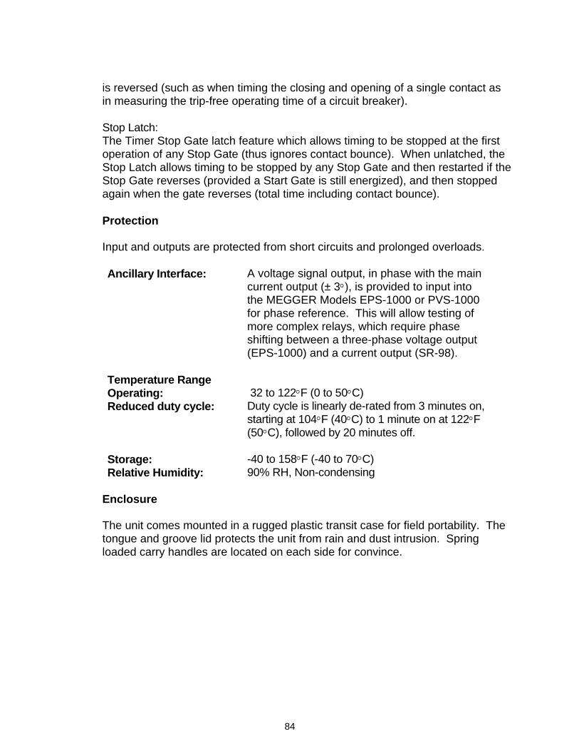
84
is reversed (such as when timing the closing and opening of a single contact as in measuring the trip-free operating time of a circuit breaker). Stop Latch: The Timer Stop Gate latch feature which allows timing to be stopped at the first operation of any Stop Gate (thus ignores contact bounce). When unlatched, the Stop Latch allows timing to be stopped by any Stop Gate and then restarted if the Stop Gate reverses (provided a Start Gate is still energized), and then stopped again when the gate reverses (total time including contact bounce). Protection Input and outputs are protected from short circuits and prolonged overloads. Ancillary Interface:
A voltage signal output, in phase with the main current output (± 3°), is provided to input into the MEGGER Models EPS-1000 or PVS-1000 for phase reference. This will allow testing of more complex relays, which require phase shifting between a three-phase voltage output (EPS-1000) and a current output (SR-98).
Temperature Range Operating: 32 to 122°F (0 to 50°C) Reduced duty cycle: Duty cycle is linearly de-rated from 3 minutes on,
starting at 104°F (40°C) to 1 minute on at 122°F (50°C), followed by 20 minutes off.
Storage: -40 to 158°F (-40 to 70°C) Relative Humidity: 90% RH, Non-condensing
Enclosure The unit comes mounted in a rugged plastic transit case for field portability. The tongue and groove lid protects the unit from rain and dust intrusion. Spring loaded carry handles are located on each side for convince.
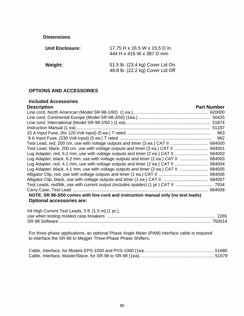
85
Dimensions Unit Enclosure: 17.75 H x 16.5 W x 15.5 D in.
444 H x 416 W x 387 D mm Weight:
51.5 lb. (23.4 kg) Cover Lid On
48.8 lb. (22.2 kg) Cover Lid Off
OPTIONS AND ACCESSORIES Included Accessories
Description Part Number Line cord, North American (Model SR-98-1/60) (1 ea.)............................................................. 620000 Line cord, Continental Europe (Model SR-98-3/50) (1ea.) ........................................................... 50425 Line cord, International (Model SR-98-2/50 ) (1 ea) ..................................................................... 51874 Instruction Manual (1 ea).............................................................................................................. 51187 15 A Input Fuse, (for 120 Volt input) (5 ea.) T rated ..................................................................... 963 8 A Input Fuse, (230 Volt input) (5 ea.) T rated ........................................................................... 962 Test Lead, red, 200 cm, use with voltage outputs and timer (3 ea.) CAT II .............................. 684000 Test Lead, black, 200 cm, use with voltage outputs and timer (3 ea.) CAT II ........................... 684001 Lug Adapter, red, 6.2 mm, use with voltage outputs and timer (2 ea.) CAT II ........................... 684002 Lug Adapter, black, 6.2 mm, use with voltage outputs and timer (2 ea.) CAT II ....................... 684003 Lug Adapter, red, 4.1 mm, use with voltage outputs and timer (2 ea.) CAT II ........................... 684004 Lug Adapter, black, 4.1 mm, use with voltage outputs and timer (2 ea.) CAT II ....................... 684005 Alligator Clip, red, use with voltage outputs and timer (1 ea.) CAT II ........................................ 684006 Alligator Clip, black, use with voltage outputs and timer (1 ea.) CAT II ..................................... 684007 Test Leads, red/blk, use with current output (includes spades) (1 pr.) CAT II .............................. 7934 Carry Case, Test Lead .............................................................................................................. 684008 NOTE: SR 98-3/50 comes with line cord and instruction manual only (no test leads) Optional accessories are:
#4 High Current Test Leads, 5 ft. [1.5 m] (1 pr.), use when testing molded case breakers ........................................................................................ 2265 SR-98 Software ........................................................................................................................... 750014 For three-phase applications, an optional Phase Angle Meter (PAM) interface cable is required to interface the SR-98 to Megger Three-Phase Phase Shifters.
Cable, Interface, for Models EPS-1000 and PVS-1000 (1ea......................................................... 51680 Cable, Interface, Master/Slave, for SR-98 to SR-98 (1ea)............................................................. 51679
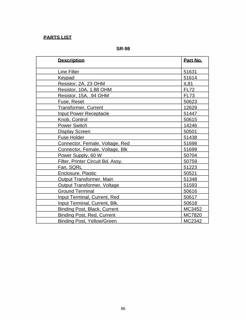
86
PARTS LIST
SR-98
Description
Part No.
Line Filter 51631 Keypad 51614 Resistor, 2A, 23 OHM IL81 Resistor, 10A, 1.88 OHM FL72 Resistor, 15A, .94 OHM FL73 Fuse, Reset 50623 Transformer, Current 12629 Input Power Receptacle 51447 Knob, Control 50615 Power Switch 14246 Display Screen 50501 Fuse Holder 51438 Connector, Female, Voltage, Red 51698 Connector, Female, Voltage, Blk 51699 Power Supply, 60 W 50704 Filter, Printer Circuit Bd. Assy. 50759 Fan, SQRL 51223 Enclosure, Plastic 50521 Output Transformer, Main 51348 Output Transformer, Voltage 51593 Ground Terminal 50616 Input Terminal, Current, Red 50617 Input Terminal, Current, Blk. 50618 Binding Post, Black, Current MC3452 Binding Post, Red, Current MC7820 Binding Post, Yellow/Green MC2342

87