Embed Size (px)
Citation preview
1
INSTRUCTION MANUAL
FOR INSTALLATION
USE AND MAINTENANCE
TYPE RNO 200
MODEL
SAVE THESE INSTRUCTIONS

2
INDEX
CHARACTERISTICS
• Scheme with legenda p.3
THE CHIMNEY FLUE
• The Chimney flue – our stoves’ “engine” p.4
• The Chimneypot p.6
• Chimney Systems p.7
INSTALLATION
• Initial advices p.17
• Installation distances from flammable material p.18
OPERATION
• Lighting and Combustion p.19
COMBUSTIBLE p.22
SAFETY
• Air inlet p.23
• Home fire safety p.24
• Ceramic lining p.26
• Advices on the Safety of Children and Adults p.26
ASSEMBLY SCHEMES p.28
MAINTENANCE p.31
WARRANTY p.32

3
SCHEME WITH LEGENDA
0,31inches
1,18 inches
1,57 inches

4
Please read this entire manual before you install and use your new room heater. Failure
to follow instructions may result in property damage, bodily injury, or even death. If you
have any doubt, please contact the selling Firm or the Producer.
THE CHIMNEY FLUE
The chimney flue: our stoves’ “engine”
The chimney flue is a key element for the optimal functioning of our stoves.
General Rules
- Each stove must have its own, adequately insulated, chimney flue to the roof;
through it the smoke will flow outside, by natural draft. DO NOT CONNECT THIS
UNIT TO A CHIMNEY FLUE SERVING ANOTHER APPLIANCE.
- the chimney flue must be separated from combustible or flammable materials
(wooden roofs, matchboards and any plastic pipes) through a suitable insulating
material, for at least 30 cm (12 inches) all around. The insulation is also
recommended when the chimney is installed inside a masonry. This will prevent
the cold air from creeping between the steel pipe and the wall. Furthermore, a
good insulation will be needed in case of passage in an open floor.
- If the chimneypot is installed on a roof lower than a higher nearby roof, the
distance must be more than 5 meters (16,50 ft). FIG. 4A
- The inner section of the chimney flue shall be uniform and without narrowings,
possibly round shaped, with smooth walls and corners not any higher than 45°.
- The section of the chimney flue must be bigger than the diameter of the stove
smoke pipe 150mm (6 inches). For our stoves we recommend a chimney flue
diameter from 160 mm to 180 mm (6 to 7 inches) and a chimney flue height of no
less than 2,5 meters (8 ft).
- The connection between the stove smoke pipe and the chimney flue in the wall
must be done through a pipe fitting (90° or 135°). Moreover, the connection must
not have more than two 90° bends and it must have an horizontal length of no
more than 2 meters (6,50 ft) with a gradient of 5%. We recommend that the
chimney flue is equipped with a condensate and soot collection chamber, which
SAFETY NOTICE: IF THIS APPLIANCE IS NOT PROPERLY INSTALLED, OPERATED AND MAINTAINED, A
HOUSE FIRE MAY RESULT.
TO REDUCE THE RISK OF FIRE, FOLLOW THE INSTALLATION INSTRUCTIONS. FAILURE TO FOLLOW
INSTRUCTIONS MAY RESULT IN PROPERTY DAMAGE, BODILY INJURY OR EVEN DEATH.
CONTACT LOCAL BUILDING OR FIRE OFFICIALS ABOUT RESTRICTIONS AND INSTALLATION INSPECTION
REQUIREMENTS IN YOUR AREA

5
shall end with an airtight door, accessible for cleaning. This will avoid unpleasant
smells, bad draft and frequent cleaning of the stove.
FIG. 2 A
FIG. 2 B
FIG. 2 C
16,40 ft

6
The Chimneypot
The chimney pot is placed on top of the chimney and helps to expell the smoke.
The fundamental characteristics of the chimneypot are:
- It must have the same diameter of the chimney flue
- useful outlet section not less than twice the minimum of the chimney flue (ex.
Chimney flue section 200 cm2
-31 inches2 – total output section holes > 400 cm
2
– 62 inches
2)
- It must prevent, through an appropriate construction, the entrance into the
chimney flue of rain and snow. In very windy areas, it is recommended to install
an appropriate chimneypot.
- It must be insulated, like the chimney flue, until its holes.
- In case the brick chimney flue has an internal pipe, this pipe shall continue until
the holes in the chimneypot.
- Avoid the output of two chimneys flues in the same chimneypot. (fig. 2D)
- If the chimneypot cannot be placed on the ridge of the roof, it should at least
be positioned so as to ensure the dispersion of smoke outside the reflux area,
in order to prevent the formation of back pression in the chimney, which can
compromise the exit of the smoke into the atmosphere.
FIG. 2 D
YES NO

7
CHIMNEY SYSTEMS
A. Venting Systems
The venting system consists of:
• A chimney connector (also known as flue or stove pipe)
• A chimney
• Thimble
These get extremely hot during use. In the event of a creosote fire, temperatures inside the chimney may
exceed 2000°F (1100°C). To protect against the possibility of a house fire:
• Chimney connector and chimney must be properly installed and maintained.
• An approved thimble must be used when a connection is made through a combustible wall to a
chimney.
• A chimney support package must be used when a connection is made through the ceiling to a factory
built chimney.
• An approved thimble and chimney support package are absolutely necessary to provide safe clearances
to combustible wall and ceiling material.
Thimble
A thimble is a manufactured or site-constructed device installed in combustible walls through which the
chimney connector passes to the chimney.
• It is intended to keep the walls from igniting.
• Site constructed thimbles must meet NFPA 211 Standards.
• Factory-built must be suitable for use with selected chimney and meet UL103 Type HT Standards.
• Follow instructions provided by the manufacturer for manufactured thimbles for masonry chimney and
factory-built chimneys.
Instructions:
1. Open inside wall at proper height for the chimney connector to entry the masonry chimney.
2. Entry hole to masonry chimney must be lined with an 8 inch (203mm) minimum diameter clay liner, or
equivalent, secured with refractory mortar.
3. Construct a 17 inch x 17 inch (432mm x 432mm) outside dimension frame from 2 x 2 framing lumber to
fit into wall opening. Inside opening of frame should be no less than 14 inch x 14 inch (356mm x 356mm).
4. Attach the wall spacer to the chimney side of the frame.
5. Nail the frame into the wall opening. The spacer should be on the chimney side.
6. Insert the section of the solid insulated chimney into the outer wall of the masonry chimney.
7. Tightly secure the length of the solid insulated chimney with the wall band to the masonry chimney.
8. Insert a section of chimney connector into the chimney. Make sure it does not protrude past the edge
of the clay chimney liner inside the chimney.
9. Seal the end of the chimney connector to the clay liner with refractory mortar.
10. Install trim collar around the sold pack chimney section.
- DO NOT INSTALL A FLUE DAMPER
- DO NOT CONNECT THIS UNIT TO A CHIMNEY FLUE SERVING ANOTHER APPLIANCE

8
FIGURE 3A
FIGURE 3B - Solid Pack Chimney with metal Supports as a Thimble
NOTE: In Canada when using a factory-
built chimney it must be safety listed,
Type UL103 HT (2100oF) CLASS “A” or
conforming to CAN/ULC-S629M,
STANDARD FOR 650oC FACTORY-
BUILT CHIMNEYS.

9
FIGURE 3C
B. Chimney Systems
• The chimney connector joins the stove to the chimney.
• It must be a 6 inch (152mm) minimum diameter 24 gauge mild steel black or 26 gauge blued steel.
• Or an approved air-insulated double wall venting pipe.
Single wall connector or stove pipe
• Must be at least 24 gauge mild steel or 26 gauge blue steel.
• Sections must be attached to the appliance and to each other with the crimped (male) end pointing
toward the stove.
• All joints, including the connection at the flue collar, should be secured with 3 sheet metal screws.
• Follow the minimum clearances to combustibles Factory-built chimney connector (vented).
Factory-built chimney connector (vented)
• The listed connectors must conform to each other to ensure a proper fit and seal.
C. Installing Chimney Components
Single wall connector or stove pipe
This must be at least 24 gauge mild steel or 26 gauge blue steel. The sections must be attached to the
appliance and to each other with the crimped (male) end pointing toward the stove. All joints, including
the connection at the flue collar, should be secured with 3 sheet metal screws. Make sure to follow the
minimum clearances to combustibles. Where passage through the wall or partition of combustible
construction is desired in Canada, the installation shall conform to CAN/CSA-B365.
Factory built listed chimney connector (vented)

10
The listed connectors must conform to each other to ensure a proper fit and seal.
FIGURE 3D
WARNING Improper installation, adjustment, alteration, service or maintenance can cause injury or property damage. Refer to this information manual provided with the appliance. For assistance or additional information consult a qualified installer, service agency or your dealer.

11
D. Factory-Built Chimney
The chimney can be new or existing, and must meet the following minimum requirements.
• Must be a 6 inch (152mm) diameter (ID) high temperature chimney listed to UL 103 HT (2100oF) or
ULC S629M.
• Must use components required by the manufacturer for installation.
• Must maintain clearances required by the manufacturer for installation.
• Refer to manufacturer instructions for installation.
NOTICE: In Canada when using a factory-built chimney it must be safety listed, Type UL103 HT (2100°F)
[1149°C] CLASS “A” or conforming to CAN/ULC-S629, STANDARD FOR 650°C FACTORY-BUILT CHIMNEYS.
FIGURE 3E – Factory built exterior chimney
WARNING Fire Risk – Follow chimney connector Manufacturer’s instructions for proper installation. ONLY use connector within the room, between appliance and ceiling or wall. Connectors shall NOT pass through: attic or roof space, closet or similar concealed space, floor or ceiling. Maintain minimum clearances to combustibles.

12
FIGURE 3F – Factory built interior chimney
WARNING Fire Risk – do NOT pack insulation or other combustibles between spacers. ALWAYS maintain specified clearances around venting and spacers. Install spacers as specified. FAILURE TO KEEP INSULATION OR OTHER MATERIAL AWAY FROM VENT PIPE MAY CAUSE FIRE.
WARNING Fire Risk – Inspection of chimney:
- chimney must be in good condition
- meets minimum standard of NFPA 211
- factory-built chimney must be 7-8 (180-200mm) UL 103 HT.
WARNING
ASPHYXIATION RISK!
• DO NOT CONNECT THIS UNIT TO A CHIMNEY FLUE SERVICING ANOTHER
APPLIANCE.
• DO NOT CONNECT TO ANY AIR DISTRIBUTION DUCT OR SYSTEM.
May allow flue gases to enter the house.

13
FIGURE 3G
E. Masonry Chimney Liner
For optimal performance, masonry chimneys used to vent this appliance should be:
1. Lined with a 6 to 8 inches (160 – 200 mm) stainless steel liner.
• Installations into a clay flue without a stainless steel liner may reduce draw which affects performance,
cause the glass to darken and produce excessive creosote.
2. It is recommended that a chimney with a larger diameter than 6-8 inches (160-200 mm) be relined.
• the oversized flue can cause poor performance and contribute to the accumulation of creosote.
3. Have the chimney cleaned before the appliance is installed and operated.
The following bullets list the more critical requirements for a properly constructed chimney:
WARNING Fire risk – When lining air-cooled factory-built chimneys:
- run chimney liner approved to UL 1777 Type HT requirements (2100 degrees F) - re-install original factory built chimney cap ONLY - DO NOT block cooling air openings in chimney - blocking cooling air will overheat the chimney

14
• The masonry wall of the chimney, if brick or modular block, must be a minimum of 4 inches (102mm)
nominal thickness.
• A chimney of rubble stone must be at least 12 inches (305mm) thick.
• The chimney must have a fire clay flue liner (or equivalent) with a minimum thickness of 5/8 inch
(16mm) and must be installed with refractory mortar.
• An equivalent liner must be a listed chimney liner system or other approved material.
• Since an oversized flue contributes to the accumulation of creosote, the size of the flue should be
checked to determine that it is not too large for the appliance.
• The chimney should also be checked to ensure it meets the minimum standard of the National Fire
Protection Association (NFPA) Standard 211.
• A chimney support package must be used when a connection is made through the ceiling to a factory
built chimney.
• An approved thimble and chimney support package are absolutely necessary to provide safe clearances
to combustible wall and ceiling material.
NOTICE: In Canada when using a factory-built chimney it must be safety listed, Type UL103 HT (2100°F)
[1149°C] CLASS “A” or conforming to CAN/ULCS629M, STANDARD FOR 650°C FACTORY-BUILT
CHIMNEYS.
FIGURE 3H

15
CHIMNEY TERMINATION REQUIREMENTS
Follow manufacturer’s instructions for clearance, securing flashing and terminating the chimney.
• Must have an approved and Listed cap
• Must not be located where it will become plugged by snow or other material
• Must be located away from trees or other structures
D. Locating Your Stove & Chimney
Location of the appliance and chimney will affect performance. The chimney should:
• Install through the warm space enclosed by the building envelope. This helps to produce more
draft, especially during lighting and die down of the fire.
• Penetrate the highest part of the roof. This minimizes the affects of wind turbulence and down
drafts.
• Consider the appliance location in order to avoid floor and ceiling attic joists and rafters.
• Locate termination cap away from trees, adjacent structures, uneven roof lines and other
obstructions.
Your local dealer is the expert in your geographic area and can usually make suggestions or discover
solutions that will easily correct your flue problem.
NOTICE:
Chimney performance may vary.
Trees, buildings, roof lines and wind conditions affect performance.
Chimney height may need adjustment if smoking or overdraft occurs.
These are safety requirements and are not meant to assure proper flue draft.
This appliance is made with a 6 inch (152mm) diameter chimney connector as the flue collar on the unit.
Changing the diameter of the chimney can affect draft and cause poor performance.
FIG. 4A
1.65 ft over
the ridge
reflux area
d> 5 ft
h min 6,56 ft
5 ft

16
1,64 ft over
the ridge
reflux area
> 4,26 ft
h min 4 ft 2,62 ft
d> 16,50 ft
1,64 ft
1,64 ft

17
INSTALLATION
VENT SPECIFICATION: six (6) inches diameter, minimum 24 MSG black or blued steel connector pipe,
with a listed factory-built UL103HT Class A chimney, suitable for use with solid fuels, or a masonry
chimney and the referenced clearances.
THIS ROOM HEATER MUST BE CONNECTED TO:
1) A chimney complying with the requirements for Type HT chimneys in the Standard for Chimneys,
Factory-Built, Residential Type and Building Heating Appliance, UL 103, or
2) A code-approved masonry chimney with a flue liner.
INITIAL ADVICES
• The stove must be installed on a floor with adequate capacity. If the existing building
does not meet this requirement, appropriate measures (eg, load distribution plate)
must be taken.
• The installation must guarantee easy access to clean the stove, the smoke pipes and
the chimney flue as well.
• Air extraction fans, when installed in the same space or room with the stove can
cause draft problems
• ALL LOCAL REGULATIONS MUST BE RESPECTED IN THE INSTALLATION OF THE
STOVE.
• Do not use the stove as an incinerator or in any other way different from the one it
has been conceived for.
• Do not use fuels different from those recommended.
• Do not use liquid fuels.
• NEVER USE GASOLINE, GASOLINE-TYPE LANTERN FUEL, KEROSENE, CHARCOAL
LIGHTER FLUID, OR SIMILAR LIQUIDS TO START OR “FRESHEN UP” A FIRE IN THIS
HEATER. KEEP ALL SUCH LIQUIDS WELL AWAY FROM THE HEATER WHILE IT IS IN
USE.
• The stove, especially the external surfaces, while it is working gets hot to the touch.
Handle carefully to avoid burns.
• Do not perform any unauthorized modification to the stove.
• Use only original replacement parts recommended by the Manufacturer.

18
INSTALLATION DISTANCES FROM FLAMMABLE MATERIAL
COMPLY WITH ALL MINIMUM CLEARANCES TO COMBUSTIBLES AS SPECIFIED. FAILURE TO COMPLY MAY
CAUSE HOUSE FIRE. Minimum installation distances from flammable material
- Minimum distance from lateral flammable wall/material: 200 mm – 8 inches
- Minimum distance from rear flammable wall/material: 200 mm – 8 inches
- Minimum distance from flammable floor: 80 mm – 3 inches
Minimum distance from front flammable material: 1000 mm – 40 inches
MINIMUM CLEARANCES TO COMBUSTIBLE MATERIALS: inches
NOTE: All “A”, “C” and “F” Dimensions are to the center diameter of flue collar.
INSTALLATION: FULL VERTICAL
SINGLE WALL PIPE A 18 B 8 C 18 D 8 E 8 F 18 G 44 H* I* J
INSTALLATION HORIZONTAL WITH MINIMUM 2 FT VERTICAL OFF STOVE TOP
SINGLE WALL PIPE A 18 B 8 C 18 D 8 E* 8 F* 18 G 44 H 23 I* J

19
OPERATION
Lighting and combustion
DO NOT USE GRATES OR ELEVATE FIRE. BUILD WOOD FIRE DIRECTLY ON EARTH.
If, during the first lighting, the stove should emanate smells due to the evaporation of
substances used in the manufacturing, it is sufficient to ventilate the room for a few hours.
Use small and medium-size logs and put them in the fireplace so that the air can penetrate
between them. Place at the base of the stack some lighters (we recommend tablet derived
from natural wax).
With the air regulation registers you can regulate the passage of primary and secondary air,
necessary for combustion and post-combustion. While lighting the stove, both registers shall
be totally opened.
This registers are placed in the base of the stove, like in the
following drawings:
The use will be as follows:
- To light the stove: air registers completely opened
- For a fast and powerful combustion: primary air register half opened – secondary air register ¾
opened
- For slow combustion: primary air register ¼ opened – secondary air register 1/3 opened.
These positions can be changed in relation to the chimney flue draft, and they are to be considered for an
insulated chimney flue with a 160 – 200 mm (6 – 8 inches) diameter and a 12 Pa draft.
ADVICE: do not close the registers completely because by doing so the combustion would be
deprived of the necessary air, giving rise to a choked combustion and to the growing of soot
on the door glass.
primary air
secondary air

20
N.B. It is also necessary to clean the fireplace area immediately behind the door from the
ashes in order to keep the primary air inlet open. The ash found in this area can be pushed
towards the back of the fireplace or removed.
Remove the ashes from the fireplace before their level is so high as to close the primary air
entrance. (see technical drawing of the stove interior below). Ashes should be placed in a
metal container with a tight fitting lid. The closed container of ashes should be placed on a
noncombustible floor or on the ground, well away from all combustible materials, pending
final disposal. If the ashes are disposed of by burial in soil or otherwise locally dispersed, they
should be retained in the closed container until all cinders have thoroughly cooled.
By using dry and seasoned wood for lighting the stove, it is possible to obtain a high flame and
to immediately activate the draft in the chimney.
When the brazier is formed on the fireplace floor, it is possible to insert larger logs (always
crossed for proper oxygenation). When the charge is burned, it will remain a substantial bed
of hot embers that will allow the charge of the fireplace, without having to perform another
lighting; in this way, you will obtain a continuous combustion.
The combustion control through the glass door will avoid repeated openings of the fireplace
and the consequent lowering of its temperature. FIREPLACE DOOR MUST BE KEPT CLOSED
DURING COMBUSTION.
fireplace door
area for
primary air inlet
remove the ashes
21
For a good yield, it is necessary to always have a good quantity of wood inside the fireplace;
without overfilling it and without pressing its ceiling and its walls (it is always advisable to
leave some space to let the air circulate and the inner refractory bricks to dilate).
In this way, the air will circulate freely while keeping a “lively” fire and the refractory bricks
will not suffer unnecessary trauma.
The combustion is good if:
- After the lighting phase, there are no visible smokes from the chimney pot.
- The ashes are gray and white and no unburned wood remains.
- There is little soot in the chimney and inside the heat exchanger.
For a good, environment friendly wood combustion, these are the conditions :
- Use only seasoned wood (at least 2 years)
- Be sure the fireplace maintains a high temperature
- During the combustion, maintain an adequate combustion air supply
- Do not overload the fireplace while lighting the stove
A bad combustion is characterized by:
- Very dense smokes
- Gray or dark yellow smoke
- Unpleasant smell
- Very dark ashes with unburned pieces of wood
- Black mouth of the chimneypot
- High wood consumption
WARNING: RISK OF BACKFIRE AND EXPLOSION
NEVER USE GASOLINE, GASOLINE-TYPE LANTERN FUEL, KEROSENE, CHARCOAL LIGHTER
FLUID OR SIMILAR LIQUIDS TO START OR “FRESHEN UP” A FIRE IN THIS HEATER. KEEP ALL
SUCH LIQUIDS WELL AWAY FROM THE HEATER WHILE IT IS IN USE.
DURING COMBUSTION, THE FIREPLACE DOOR MUST REMAIN CLOSED. Whenever you need
to open the door to introduce wood in the fireplace, open the air registers for a few seconds
before doing it.
Use the heat glove supplied to open the door and to reload the fireplace. By doing so you will
be able to put the logs gently into the fireplace, avoiding unnecessary trauma to the refractory
bricks.
Warning: the proper use of the heat glove is for charging the fireplace and NOT to remove
glowing embers from it.
During combustion, some parts of the stove (door, handle, glass) can reach high temperatures
so it is necessary to be careful and to use precautions.
If during combustion, loss of smoke should occur, do not charge anymore wood, ventilate the
room immediately and cool the stove. When the stove is cold, check the reason of the loss
and, if necessary, contact the Manufacturer.
However, if the smoke comes out from the stove while loading it, ventilate momentarily the
room and continue to load more slowly, giving time to ignite the wood.

22
THE FIREPLACE DOOR MUST BE KEPT CLOSED during lighting (only the moment in which you
light the lighter under the wood, then close it), charging and embers removing, in order to
avoid smoke escape.
For night operating, use large size logs and possibly of hard species (beech, oak, etc..) and if
the wind and draft conditions are reasonably stable, the stove will continue to burn calmly. If
you want to prolong the combustion for many hours, you may need to adjust the air
regulators to a minimum.
COMBUSTIBLE
THE PROPER COMBUSTIBLE IS WOOD LOGS.
Commercial firewood is usually divided into soft wood and hard wood. The hard species are
characterized by a strong and heavy wood and provide a substained and persistent flame
(eg. Beech, Ash, Walnut, etc..)
The soft species, light and soft wood, provide a short term flame (eg. Chestnuts, Poplars,
Birch, etc.)
The resinous species (eg. Larch, Spruce, European species of Pine) while providing a
significant amount of heat during combustion, have some drawbacks described below:
- Have a low specific weight and therefore burn quickly
- Contain resin, have a rather sooty combustion and therefore require more
frequent chimneys and stove cleaning
- They produce hot particles
- They produce few embers
It is recommended to burn strong wood (eg. Beech, oak, etc.) and especially not to burn:
garbage, painted wood, plywood or particle board, fibreboard or packagings because it could
damage the stove and the chimney flue.
It is important to burn dry and seasoned wood, at least two years, since humidity has a
significant influence on the quality of combustion. Infact, when the wood is very wet, it
lower the combustion temperature, and also the first part of combustion is used to dry the
wood at the expense of yield. Moreover, this lowers the temperature of the smoke and
creates condensation and creosote which is very dangerous, flammable and with an
unpleasant smell.

23
SAFETY
Air inlet
The stove must have the necessary air so as to ensure a regular combustion and a healthy
environment, so:
- Make sure that in the room where the stove is installed there is adequate
ventilation, the minimum recommended section is > 80 cm2
(12 inches2) for
devices with closed fireplace
- The air intake must be directly communicating with the room in which the
stove is installed. Avoid any obstruction and protect it with a grid as long as it
does not reduce the minimum section.
- The adjacent room cannot be used as a garage, storage of combustible
material or for activities with risk of fire.

24
HOME FIRE SAFETY
Installation and use of the stove should be in accordance with the instructions of the
Manufacturer and the local rules of habitability.
• When a flue pipe pass through a wall or ceiling particular methods of installation
should be applied (protection, thermal insulation, distance from heat sensitive
materials, etc)
• NEVER CONNECT THE STOVE TO A CHIMNEY FLUE ALREADY IN USE FOR ANOTHER
DEVICE.
• Keep away from the fireplace radiation area all combustible and flammable materials
(wood furniture, curtains, flammable liquids, etc…)
• If nearby there are shells in combustible or sensitive to heat materials, an insulating
and not combustible protection must be interponed.
• If the floor is made in combustible material, at the mouth of the fireplace a
protection made of incombustible material (i.e. inox steel, stone, glass) should be
placed – with a lateral extension of 203mm (8 inches) and a frontal extension of
406mm (16 inches). Under the chimney connector: 2 inches (51 mm) beyond each
side.
FLOOR PROTECTION REQUIREMENTS:
• Use of a floor protector listed to UL 1618
• Type 1 (ember) floor protector or ½” non-combustible material.
• Extend beneath appliance and to the front, sides and rear as indicated in the diagram
below
• The floor must be non-combustible or otherwise adequately protected from sparks
and falling embers.
• A layer of thin brick or ceramic over a combustible is sufficient.
• In US installations, it is necessary to install a floor protector of non-combustible
material a minimum of 16 inches (406 mm) in front of glass and 8 inches (203 mm) to
both sides of the fuel loading door. Open the door and measure 8 inches (203mm)
from the side edge of the opening in the face of the appliance. see exception

25
• In Canada, it is necessary to install a floor protector of non-combustible material a
minimum of 18 inches (457mm) in front of glass and 8 inches (203mm) to both sides
and back of the appliance. see exception
• EXCEPTION: non-combustible floor protections must extend beneath the flue pipe
when installed with horizontal venting and extend 2 inches (51mm) beyond each
side.
• WARNING! RISK OF FIRE! Hearth pads must be installed exactly as specified. High
temperatures or hot embers may ignite concealed combustibles.
To provide reasonable fire safety, the following should be given serious consideration:
1. Install at least one smoke detector on each floor of your home to ensure your safety. They should be
located away from the heating appliance and close to the sleeping areas. Follow the smoke detector
manufacturer’s placement and installation instructions, and be sure to maintain regularly.
2. A CO detector should be installed in the room with the appliance.
3. A conveniently located Class A fire extinguisher to contend with small fires resulting from burning
embers.
4. A practiced evacuation plan, consisting of at least two escape routes.
5. A plan to deal with a chimney fire as follows - In the event of a chimney fire:
a - Evacuate the house immediately
b - Notify fire department
Negative pressure results from the imbalance of air available for the appliance to operate properly. It
can be strongest in lower levels of the house.
Causes include:
• Exhaust fans (kitchen, bath, etc.)
• Range hoods
• Combustion air requirements for furnaces, water heaters and other combustion appliances
• Clothes dryers
• Location of return-air vents to furnace or air conditioning
• Imbalances of the HVAC air handling system
• Upper level air leaks such as:
- Recessed lighting
- Attic hatch
- Duct leaks
INSTALLATION DISTANCES FROM FLAMMABLE MATERIAL
Minimum installation distances from flammable material:
-minimum distance from lateral flammable wall: 200mm – 8 inches
-minimum distance from flammable rear wall: 200mm – 8 inches
-minimum distance from flammable floor: 80mm – 3 inches

26
Minimum front distance from flammable material: 1000 mm – 40 inches
NOTICE: LA CASTELLAMONTE assumes no responsibility for the improper performance of the appliance
system caused by:
• Inadequate draft due to environmental conditions
• Downdrafts
• Tight sealing construction of the structure
• Mechanical exhausting devices
• Overdrafting caused by excessive chimney heights
CERAMIC LINING
• The various ceramic parts must be handled with extreme care.
• Check the leveling of the floor where the stove will be installed.
• If you notice that the packaging is damaged or any lack of professionalism of the
transporter at the stove delivery, sign the note with words “subject to control”.
• The installation must be done by at least two persons, carefully following the
installation instructions provided in this manual.
ADVICE ON THE SAFETY OF CHILDREN AND ADULTS
During the stove functioning, the ceramic coating heats up progressively (until
40 / 50 °C) to give heat to the environment. It is very important to keep the
children away from the stove in order to avoid touching the ceramic coating,
with the risk of burns.
In addition, the ceramic glass and the metal door of the fireplace can get red
hot; it is therefore essential to avoid touching these parts or leaving the stove
lighted in the presence of unattended children.
As a general rule, it is essential to closely monitor children who are close to the
lighted stove and to prevent them from touching it or attempting to open the
fireplace door.
In relation to the instructions above, it remains at the Customer discretion the
decision to install a protective shield around the stove or in front of the
fireplace door.

27
HOT SURFACES!
Glass and other surfaces are hot during operation AND cool down. Hot glass
will cause burns.
• Do not touch glass until it is cooled
• NEVER allow children to touch glass
• Keep children away
• CAREFULLY SUPERVISE children in same room as appliance.
• Alert children and adults to hazards of high temperatures
• High temperatures may ignite clothing or other flammable materials.
• Keep clothing, furniture, draperies and other flammable materials away.

28
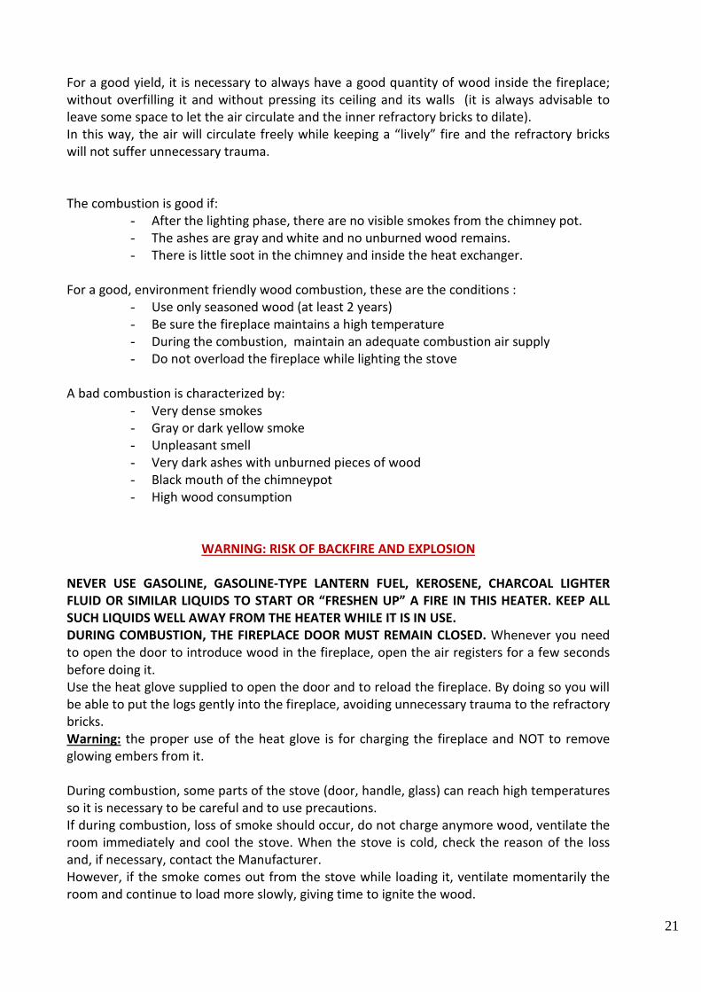
ASSEMBLY SCHEMES

29
ASSEMBLY SCHEMES
30
ASSEMBLY SCHEMES

31
MAINTENANCE
The installation of the stove must guarantee easy access for its cleaning, as well as for the
cleaning of the flue pipes and of the chimney flue.
All maintenance operations must be carried out on the stove off and cold.
Ash disposal
The removal of the ashes from the fireplace is made with the proper paddle directly from the
fireplace floor. All this must be done with the stove off and cold.
Remove the ashes from the fireplace before their level is so high as to close the primary air
entrance. (see technical drawing of the stove interior – fig. 13 page 11). Ashes should be placed
in a metal container with a tight fitting lid. The closed container of ashes should be placed on a
noncombustible floor or on the ground, well away from all combustible materials, pending final
disposal. If the ashes are disposed of by burial in soil or otherwise locally dispersed, they should
be retained in the closed container until all cinders have thoroughly cooled.
Stove and chimney flue cleaning
When wood is burned slowly, it produces tar and other organic vapors which combine with
expelled moisture to form creosote. The creosote vapors condense in the relatively cool
chimney flue of a slow burning fire. As a result, creosote residues accumulates in the flue lining.
When ignited, this creosote makes an extremely hot fire. The chimney connector and chimney
should be inspected at least once every two months during the heating season to determine if a
creosote buildup has occurred. If creosote has accumulated it should be removed to reduce the
risk of a chimney fire. In normal conditions, where no creosote accumulates, the stove, the flue
pipes and the chimney flue can be cleaned once a year.
Heat exchanger cleaning
For the internal cleaning of the heat exchanger: lift the ceramic top cover, unscrew the door on
the exchanger (it is recommended to moisten the screws with special lubrificants before
starting to loosen) and check that the space between the tubes is free, otherwise remove the
soot with a special brush and vacuum cleaner.
Ceramic cleaning
The ceramic lining should be cleaned with a soft and dry cloth. DO NOT WET AND NEVER CLEAN
THE CERAMIC WHILE IT IS HOT, THE THERMIC SHOCK COULD BREAK IT.
Glass cleaning
Do not clean the glass with materials that can scratch or damage it, the scratches could develop
into cracks or breaks.
Do not clean the glass when it is hot, but wait until it cools down.
Use wet cloth with warm water or with suitable products.
We suggest the need for regular maintenance by the Manufacturer or by a qualified technician.

32
WARRANTY
La Castellamonte will replace or repair the goods or its individual components when they are
found in lack of conformity which existed at the time the goods were delivered in the
manner and extent permitted by the law. (d. lgs 206/05)
The warranty does not cover defects caused by the purchaser as a result of negligent use, by
the use of not suitable fuel and with a moisture content above 15%, by maintance
performed by unauthorized persons, by modifications and substitutions of individual
components, by a poorly built and not suitable chimney flue.
This warranty does not extend to the refractory bricks inside the fireplace, because their
duration depends on how wood is loaded by the User.
The cost of repair or replacement of the goods shall be borne by the Seller. The buyer agrees
to make use of this warranty, subject to revocation, to inform the Seller of any lack of
conformity within 8 days of discovery.
The warranty period is 2 years from delivery.
In addition to the legal warranty, the Seller guarantees the ceramic parts for an additional
period of 1 year.

33
LA CASTELLAMONTE di R. Perino e S. Neri Snc
Via Casari 13, s.n. – Tel. e fax 0039 124 581690 – 0039 124 514149
10081 Castellamonte (TO) – Italy
www.lacastellamonte.it
www.stackstoves.com
e-mail: [email protected]