Embed Size (px)
DESCRIPTION
engineering
Citation preview

MECHANICAL CONTRACT NUMBER :
TP.01.03/U.DEP.IP.SKG/1275/X/
2013
NO DOKUMEN
20 PAGES
PAKET 1 : JASA PERANCANGAN, PENGADAAN DAN KONSTRUKSI PEMBANGUNAN SKG RANTAU PANJANG DAN SKG PANGKALAN
BRANDAN
FUEL GAS FILTER INSTRUCTIONS FOR INSTALATION
A 21/08/14 Issued for Information my af IWK
Rev. Date Status Prep'd Checked Approved Checked Approved
PT. SURYA BESINDO SAKTI PT. WIKA PERTAGAS
PAKET 1 : JASA PERANCANGAN, PENGADAAN DAN KONSTRUKSI PEMBANGUNAN SKG RANTAU PANJANG DAN SKG PANGKALAN BRANDAN
Rev. 0 FUEL GAS FILTER INSTRUCTIONS
FOR INSTALATION
Date : 21 /08/14
Page 2 of 20
REVISION SHEET
Page REVISION CODE
Page REVISION CODE
Appendix REVISION CODE
A B C D 0 1 2 A B C D 0 1 2 A B C D 0 1 2
1 X
2 X
3 X
4 X
5 X
6 X
7 X
8 X
9 X
10 X
11 X
12 X
13 X
14 X
15 X
16 X
17 X
18 X
19 X
20 X
21
22
23
24
25
26
27
28
29
30

PAKET 1 : JASA PERANCANGAN, PENGADAAN DAN KONSTRUKSI PEMBANGUNAN SKG RANTAU PANJANG DAN SKG PANGKALAN BRANDAN
Rev. 0 FUEL GAS FILTER INSTRUCTIONS
FOR INSTALATION
Date : 21 /08/14
Page 3 of 20
REVISION SHEET
Rev. Code
Chapter Page Note Implementation
Comment (Yes/No) Remarks
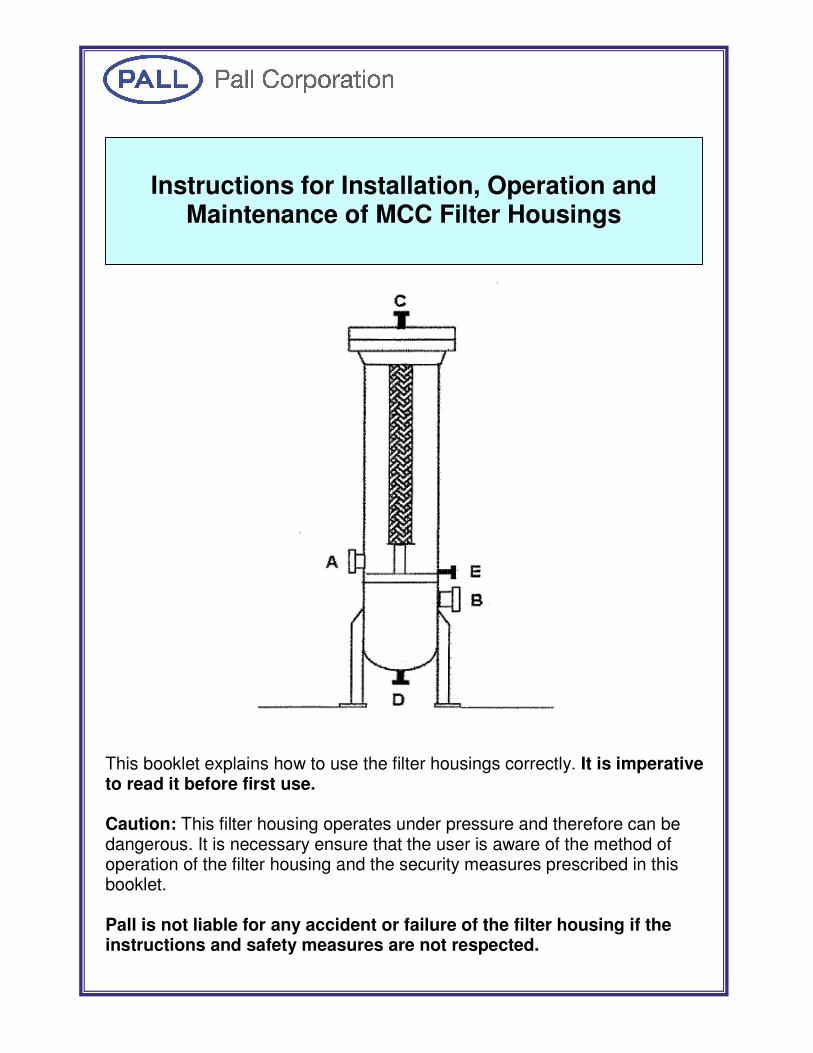
This booklet explains how to use the filter housings correctly. It is imperative to read it before first use. Caution: This filter housing operates under pressure and therefore can be dangerous. It is necessary ensure that the user is aware of the method of operation of the filter housing and the security measures prescribed in this booklet. Pall is not liable for any accident or failure of the filter housing if the instructions and safety measures are not respected.
Instructions for Installation, Operation and
Maintenance of MCC Filter Housings

Doc No: Pall-MCC-IOM
Page 2 of 13
CONTENTS
ITEM PAGE
1 FOREWORD......................................................................................................................... 3
2 DESCRIPTION ..................................................................................................................... 4
2.1 Design................................................................................................................................ 4
2.2 Scope of supply.................................................................................................................. 4
3 SAFETY PRECAUTIONS .................................................................................................... 5
4 INSTALLATION .................................................................................................................. 6
4.1 Storage............................................................................................................................... 6
4.2 Pre-Installation................................................................................................................... 6
4.3 Location and Mounting ...................................................................................................... 7
4.4 Connection to System Pipework......................................................................................... 7
4.5 Installation of filter cartridges............................................................................................. 8
4.6 Commissioning of the Filter ............................................................................................... 9
5 OPERATION OF FILTER HOUSING & FILTER CARTRIDGES REPLACEMENT ........ 10
5.1 Operation of Filter Housing.............................................................................................. 10
5.2 Shut Down ....................................................................................................................... 10
5.3 Replacement of filter cartridges........................................................................................ 11
6 MAINTENANCE ................................................................................................................ 12
7 ACCESSORIES AND SPARE PARTS ............................................................................... 13

Doc No: Pall-MCC-IOM
Page 3 of 13
1 FOREWORD
This manual is provided to serve as the installation, operation and maintenance guide for the
equipment supplied in accordance with the details given in the customer’s purchase order. The
contents should be read before attempting any phase of installation, operation and maintenance.
Symbols used throughout this manual are defined below:
THESE CALL ATTENTION TO A HAZARD WHICH MAY BE A THREAT TO THE HEALTH OR WELL BEING OF PERSONNEL.
These call attention to instructions which must be followed to avoid damaging the product, equipment or surroundings.
These call attention to information that will aid operation and/or installation of the equipment.
These call attention to an electrical hazard which may be a threat to the health or well being of personnel, or that may damage product,
equipment or surroundings.
Pall Corporation provides the recommendations present in this document with the understanding
that Pall will not be held liable for any unforeseen outcomes of the enclosed guidelines. This
information is the property of Pall Corporation, as is furnished for use of the assigned recipient
only.
!

Doc No: Pall-MCC-IOM
Page 4 of 13
2 DESCRIPTION
2.1 Design
The filter housing comprises a cylindrical vessel closed at the lower end by a dished end and at the
upper end by a blind flange. For full details of components and materials used refer to the general
arrangement drawing.
Nozzles are provided in the vessel for inlet, outlet, drain and vent. For full details of nozzle sizes
and identification numbers, refer to appropriate GA drawing.
The housing is supported in its operating position on legs welded to the vessel exterior.
The filter housing is designed to hold multiple MCC style filter cartridges, with flow direction that
is outside to inside.
The filter housing is designed as per user’s requirements and specifications to ensure the
mechanical strength and optimum output.
The user is responsible to check if the nature of the fluids is compatible with the material of the
filter housing.
2.2 Scope of supply
This filter housing is delivered ready to be installed. The user is responsible to provide and install
any other components necessary for its utilization, notably safety valves, taps, pressure gauges etc.
PRESSURE OVERLOAD MUST NOT UNDER ANY CIRCUMSTANCE
EXCEED THE AUTHORIZED MAXIMUM PRESSURE FOR THE
FILTER HOUSING. !

Doc No: Pall-MCC-IOM
Page 5 of 13
3 SAFETY PRECAUTIONS
Even though the filter housing is designed to be used with fluids as per specified in datasheet, it is
necessary that the user ensures that the fluid does not contain under any circumstance substances
that, individually or mixed with others, may provoke an explosion or fire.
The products or mixture of products that may be used must under no circumstances contain
halogenous substances capable of provoking rapid, irreversible corrosion.
Any direct contact with ferrous elements is forbidden. The contamination by iron can provoke a
rapid acceleration in corrosion. Any accidental contamination must be eliminated immediately.
This equipment has been tested and quality controlled in accordance with Pall’s standard
procedures and in accordance with the tests specified in the contract. However, the equipment as
shipped may have been opened or disassembled for draining, cleaning, etc., after testing. The user
should ensure that all bolts, flanges, pipes, closures or other accessories have not worked loose
during shipment and should tighten them wherever necessary.
A nameplate has been permanently attached to this equipment. When requesting information,
service, and spare parts; please refer to information given on the nameplate.
NEVER OPEN FILTER HOUSING UNDER PRESSURE.
1. Before each start-up, ensure that seals are in good conditions, replace them
if necessary.
2. Removed contained air using the vent before start-up.
3. Use protective equipment if the nature of the fluid requires it.
4. Raise pressure progressively (to avoid water hammers).
5. Respect thoroughly the conditions of use indicated on the filter housing
(maximum temperature and maximum pressure).
6. Always depressurize the filter housing before opening it.
!

Doc No: Pall-MCC-IOM
Page 6 of 13
4 INSTALLATION
IF THE PROCESS FLUID IS TOXIC OR HAZARDOUS, ALL SAFETY REGULATIONS AND
PROCEDURES ASSOCIATED WITH THE FLUID MUST BE OBSERVED WHEN
OPERATING OR SERVICING THE UNIT. FAILURE TO DO SO COULD RESULT IN
PERSONAL INJURY AND/ OR DAMAGE TO THE EQUIPMENT.
4.1 Storage
If the filter housing and filter cartridges are not to be installed immediately:
� Store in clean, dry conditions and wherever practical in the packaging
supplied.
� DO NOT remove from packaging until ready to install.
� To prevent accidental internal contamination retain the nozzle blanks in
position until ready to connect to the system.
4.2 Pre-Installation
It is the user’s responsibility to check actual operating conditions to ensure that the filter media,
housings and sealing materials are compatible with the application and are within local safety
codes.
Step # Description
1 � Prior to installation check that the housing pressure and flow
are compatible with the system specification.
2 � Remove all protective shipping framework, covers and
shipping packaging.
3
� It is recommended that all housing nozzle blanks are left in
place until connection is made to the system pipe work to
prevent the ingress of local contaminants.
4
� Inspect the filter housing on arrival for possible damage.
� If damage has occurred, immediately enter a claim with the
carrier, if necessary contact Pall Corporation.
5
� The filter housing will have been inspected and tested to the
required specifications prior to leaving the factory.
� Ensure that no nuts, bolts, flanges or other components have
come loose in transit.
6
� All components must be inspected by the customer before
putting the housing on stream to ensure that:
o all external and internal packaging has been removed
o no extraneous materials or undesirable contaminants
are present
o the filter housing internals are sufficiently clean for
use.
� Consult Pall Corporation if advice is required on cleaning
procedures relevant to the equipment supplied.
1
Check pressure and flow
are compatible with
system specifications.
2
Remove packaging and
shipping framework
3
Check nozzle blanks are
in place
4
Inspect housing for
damage
5
Ensure nuts, bolts and
flanges are secure
6
Inspect of extraneous
materials and cleanliness

Doc No: Pall-MCC-IOM
Page 7 of 13
4.3 Location and Mounting
• Appropriate load rated lifting equipment must be used, and safe lifting procedures
observed during all movements of the skid package. Lifting gear must be safely
connected to the filter housing.
• Locate the filter housings in a position that allows adequate access to all components for
maintenance and servicing purposes. Secure in place using holding down bolts through
the holes in the leg assembly.
• Fit isolation valves at the inlet and outlet (not in scope of supply).
• Connect the inlet and outlet pipes to the positions marked on the vessel. The fluid should
always flow from the outside to the inside of the filter cartridges.
• A housing vent line must be connected to a flare or vent line to facilitate housing
depressurization. Installation of an inlet/outlet vent on the vent port is strongly
recommended. Depending on the fluid to be filtered, a security system should be
provided to avoid exposure to any projection fluid.
• Ensure that drain ports are easily accessible.
• Installations of pressure gauges at the inlet and outlet of the filter housing are strongly
recommended or alternatively, a differential pressure gauge may be used. This is to
allow for monitoring of system pressure and differential pressure across the filter
cartridges.
4.4 Connection to System Pipework
Remove all housing nozzle blanks before connecting the flanges to the system pipework.
ENSURE THAT THE CONNECTIONS OF THE SYSTEM PIPEWORK ARE
COMPATIBLE WITH THE FILTER HOUSING CONNECTIONS. USE OF
INCORRECT CONNECTIONS CAN CAUSE FAILURE RESULTING IN
PERSONAL INJURY, LOSS OF PRESSURE AND POSSIBLE SYSTEM
FAILURE.
All pipework must be connected in accordance with current good engineering practice, ensuring
that the correct process fluid flow is obtained.
Note: Piping supports should be provided as close as is practicable to the nozzle connections in
order to minimise external loads.
It is recommended that pressure gauges or sensing devices are installed in the
system to allow the monitoring of the system pressure and the differential
pressure across the cartridges.

Doc No: Pall-MCC-IOM
Page 8 of 13
IF THE PROCESS FLOW IS TOXIC OR HAZARDOUS, ALL DRAINS AND
VENTS MUST BE PIPED TO SAFE OUTLETS USING SUITABLE
EQUIPMENT
4.5 Installation of filter cartridges
No special tools are necessary for filter cartridges installation. The filter cartridge is fixed to the
tubesheet by means of o-ring.
ENSURE THAT THE FILTER HOUSING IS DEPRESSURISED BEFORE
ATTEMPTING TO REMOVE THE BLIND FLANGE.
Step # Description
1 � Open the top blind flange.
2 � Verify that the filter cartridge part number corresponds to
the application.
3 � Cut open the protective bag. DO NOT open by pushing
the filter cartridges through the bag.
4 � Remove the filter hold down plate.
5
� It is recommended that the o-ring is lubricated with
compatible lubricant. (eg. Silicon grease)
� Carefully install Pall filter cartridge into the tubesheet,
ensuring it seals firmly.
� Push down firmly.
� No special tools are required for filter cartridge
installation
6
� Upon completion of the installation of the filter cartridge,
ensure all tools are removed from the housing interior.
� Replace filter hold down plate.
7 � Close the top blind flange.
1
Open top blind flange
2 Verify filter cartridge part
number
3 Remove filter cartridge
from bag.
4
Remove hold down plate.
5
Install Filter cartridges
6 Remove all tools
7 Close top blind flange

Doc No: Pall-MCC-IOM
Page 9 of 13
4.6 Commissioning of the Filter
In order to protect the filter cartridges from damage during re-pressurisation after maintenance or
filter cartridge replacement, pressure indicators must be installed into the system to allow for
monitoring of system pressure and differential pressure across the filter cartridges. The operator
must avoid sudden high-pressure differentials across the filter cartridges during start-up, and ensure
they are not subject to excessive differential pressure exceeding 1 bar.
A FULL HAZARD OPERATION PERFORMANCE STUDY SHOULD BE
CARRIED OUT BY THE END USER PRIOR TO THE OPERATION OF THE
EQUIPMENT.
A housing vent line must be connected to a flare or vent line to facilitate housing depressurization.
Refer to general arrangement drawing for installation dimensions and connections.
Following installation of the filter cartridges it is essential to check the operation and integrity of the
vessel prior to start up. The filter housings must be commissioned and tested for any leakage, in
accordance with the following procedures:
Step # Description
1 � Isolate filter housing by closing the main
inlet valve and the main outlet valve)
2 � Open vent valve.
3 � Slowly open the inlet valve so the housing
can be pressurized gradually.
4 � Close vent valve when liquid starts to flow
through the vent (avoid discharge).
5
� Check the housing for leaks.
� If any leaks are apparent, shut down the
housing following the instructions in the
shut down section
6 � If no leaks are apparent, fully open the inlet
valve
7 � Slowly open the full flow outlet valve in
order to prevent flow surges.
8
� Once full process flow is achieved through
the housing, note the differential pressure
and flow rate. This is the initial clean
pressure drop.
Irrespective of the housing pressure or flowrate, the differential pressure
across the filter cartridges during start up should not exceed 1 bar. Exceeding
this will cause damage to the filter cartridges. !
1
Isolate filter housing
2 Open vent valve
3
Open Inlet Valve
4
Close vent valve
5
Check for leaks
No
6 Open full flow inlet
valve
7 Open full flow outlet
valve
8 Note initial clean &
dry dP and flow rate
Leaks
detected?
Go to
Shutdown
procedure
Yes

Doc No: Pall-MCC-IOM
Page 10 of 13
5 OPERATION OF FILTER HOUSING & FILTER CARTRIDGES
REPLACEMENT
5.1 Operation of Filter Housing
Retention of particles by filter housing will progressively plug the filter and increase the pressure
drop. The differential pressure should be checked and recorded regularly.
At ambient temperatures, Pall recommends replacement of the filter cartridges, as appropriate,
when the pressure drop exceeds 1 bar. Frequent replacement of seals is also advisable.
FOR OPTIMUM FILTRATION
USE EXCLUSIVELY PALL FILTER CARTRIDGES
During normal operation process fluid enters the filter housing through the inlet nozzle. The flow
of the fluid is outside to inside of filter cartridges.
The condition of filter cartridges must be monitored by a differential pressure gauge or pressure
sensing device showing the differential pressure between the inlet and outlet pressures of the
housing.
The fluid then exits the housing via the outlet nozzle.
The filter cartridges should be cleaned or replaced before the limiting differential pressure for the
process and the filter cartridge is reached. Maximum dP recommended is 1 bar. Exceeding this
dP will damage the filter cartridges.
5.2 Shut Down
Step # Description
1 � Close the full flow inlet valve. 2 � Close the full flow outlet valve.
3
� Open the vent valve and gradually depressurize the
housing.
Note: The Filter cartridges must not be subject
to reverse flow during venting of the housing,
as they will be damaged
4 � Open the drain valve and allow the filter housing to fully
drain.
5 � Open the housing.
1 Close inlet valve
2 Close outlet valve
3 Open vent valve to
depressurise housing
4
Open drain valve
5
Open the housing

Doc No: Pall-MCC-IOM
Page 11 of 13
5.3 Replacement of filter cartridges
BEFORE PROCEEDING ANY FURTHER ENSURE THAT NO RESIDUAL
PRESSURE EXISTS IN THE FILTER HOUSING AS INDICATED BY THE
PRESSURE GAUGES OR SENSING DEVICES INSTALLED IN THE
SYSTEM. OPENING THE VESSEL WHILE UNDER PRESSURE COULD
RESULT IN PERSONAL INJURY AND/OR DAMAGE TO THE
EQUIPMENT.
The new filter cartridges and o-rings must not be soiled or damaged during
the replacement.
Step # Description
1 � Ensure that the housing is isolated and depressurized
2 � Remove used filter cartridges
3 � Check that the housing gasket is in good condition,
replace if necessary.
4 � Reinstall new filter cartridges as detailed in Section
4.5.
5 � Re-commission the housing as detailed in Section 4.6.
!
2
Remove filter cartridges
1 Ensure housing isolated
and depressurised
3 Ensure housing gasket is
in good condition.
4 Re-install new filter
cartridges.
5
Recommission housing

Doc No: Pall-MCC-IOM
Page 12 of 13
6 MAINTENANCE
Pall filtration equipment should give long and trouble free service if reasonable preventive
maintenance procedure is followed.
For spare parts, required for maintenance or repair, refer to General
Arrangement Drawings.
BEFORE ATTEMPTING TO REMOVE FILTER CARTRIDGES OR
ASSOCIATED PIPING ENSURE THAT THE FILTER HOUSING IS
ISOLATED AND DEPRESSURISED. FAILURE TO DO SO COULD
RESULT IN PERSONAL INJURY AND/OR DAMAGE TO THE
EQUIPMENT.
Step # Description
1
� Monitor the differential pressure across the housings.
� When the maximum differential pressure allowed
across the housing of 1 bar is reached, shut down,
isolate and depressurise the housing.
� Replace the filter cartridges in accordance with
section 4.5.
2
� Check for any leakage.
� If a leak develops, shutdown, isolate and
depressurise the housing and replace the seal at the
leak.
3
� Replace the filter cartridge:
o When the maximum differential pressure of 1
bar across the filter cartridge is reached.
o As required by the customer’s own
procedures, but not exceeding filter cartridge
specifications.
4
� Clean the housing interior:
o At filter cartridge removal.
o As required by the customers own laid down
procedures.
1 Monitor dP across
housings
2
Check for leaks
3
Replace filter cartridges.
4
Clean housing interior

Doc No: Pall-MCC-IOM
Page 13 of 13
7 ACCESSORIES AND SPARE PARTS
Only original Pall spare parts should be used with this product.
Spares can be ordered from Pall Corporation or local representative.
When ordering these spare parts, please specify Pall Filter Cartridge part number.

DescriptionThe MCC1401 filter cartridge is available in two basictypes of media; Epocel® – which is a resin impregnatedcellulose, and Ultipor® – a resin bonded glass fiber. Theseabsolute rated media, specifically engineered, are availablein varying grades with defined removal efficiencies and canprovide up to 54 square feet of effective filtering surfacearea assuring long service life. See Table 1 for removalratings of each medium type.
Operating CharacteristicsMCC1401 cartridges are of pleated design, supportedinternally by a steel core and protected externally by steelendcaps, providing positive sealing via an internal O-ring.The maximum recommended changeout differentialpressure is 60 psid/4.13 bar at 275˚F/135˚C.
Filter Media CharacteristicsUltipor Filter Cartridges: These cartridges are ruggedlybuilt using a resin bonded glass fiber medium. The inertresin bonding ensures that the filters are free from mediamigration and establishes a permanent, fixed poreconstruction that prevents unloading of trappedcontaminants. Because of their high effective filter areaand optimized construction, Ultipor elements provide highdirt holding capacity, low clean pressure drop, long servicelife and low cost per gallon of fluid processed.
Epocel Filter Cartridges: This filter medium iscomprised of a resin impregnated cellulose medium.Utilizing the resin impregnation technique locks thecellulose fibers in place preventing flexing or shifting,which can change the size of the flow passages andreduce removal efficiency. Epocel medium is compatiblewith many fluids including fresh and produced water,acids, solvents, brines, hydrocarbons, alcohols, and manyothers. Epocel cartridges are available in grades rangingfrom 10 micron up to 50 micron absolute.
ApplicationsFluid Processing: Solvents, acids, chemicals,hydrocarbons, water and other fluids used in refinery,chemical and petrochemical processing always carrysome harmful particles that must be removed. MCC1401cartridges provide the fine filtration necessary toadequately clean up these fluids. Their durability, largeamount of filtration area and high dirt capacity haveproven to be most beneficial for this type of filtering.
High Pressure Gas Streams: Finer grades of theMCC1401 cartridge, offered for use in gas systems, willremove over 99.98% of all solid aerosols suspended in agas stream. The effluent gas, produced after Pall filtration,will not plug sensitive instruments or foul critical machinecomponents such as a compressor or turbine blades.
High Pressure Water Injection and Disposal: The MCC1401 high pressure filter cartridge providesreproducible high quality injection fluids for your waterfloodand enhanced oil recovery operation. Injecting high qualityfluids reduces formation damage, maintains stable injectionprofiles, and increases sweep efficiency that lowersoperating expenses because of less frequent workovers.
MCC1401 High Pressure FilterCartridge Providing Reliability andEconomical Filtration for SuperiorFluid Quality
Element Data Sheet WER 5106i
MCC1401 Filter Cartridge

Table 1. MCC1401 Elements – Performance Characteristics
Cartridge Liquid Removal Rating Gas Removal Effective Media Element AqueousPart Number Rating Area3 Description Pressure Drop
Percent PercentRemoval 99.98%1 99% 90% Removal6
Beta2, 5 5000 100 10 Sq. ft. psid/gpm mbar/lpm
MCC1401U2-20ZH13 (2) (4) 2.0 0.8 0.3 >99.99 at 54 Ultipor Resin 0.021 0.3820.3 micron Bonded Glass
MCC1401U6-40ZH13 (2) (4) 2.5 <1.0 <1.0 >99.98 at 53 Ultipor Resin 0.0015 0.0270.3 micron Bonded Glass
MCC1401E100H13 (2) (4) 10.0 5.0 <2.0 95.7 at 37 Epocel Resin 0.005 0.0910.3 micron Impregnated
Cellulose
MCC1401E280H13 (2) (4) 23.0 16.0 8.0 45 Epocel Resin 0.002 0.036ImpregnatedCellulose
MCC1401E500H13 (2) (4) 50.0 44.5 27.0 45 Epocel Resin 0.0017 0.031ImpregnatedCellulose
(1) Absolute Filtration Rating: The absolute rating can be operationally definedas βλ = 5000 or 99.98% removal efficiency at any given size. Note: This is the limit of the sensitivity of the rating method.
(2) Beta Value (β): β is the ratio of the number of particles equal to a given sizeor larger in the influent compared to those of the same size or larger in theeffluent. β is related to the removal efficiency by:Removal Efficiency % = β-1 x 100
β(3) Area listed is for basic 33⁄4″ O.D. by 40″ nominal length cartridge.(4) Ratings determined using 0.5 µm to 40 µm siliceous contaminant for
MCC1401U2-20. For other MCC1401 cartridges, ratings determine usingAC-Fine Test Dust in a water dispersion for a test system.
(5) Specially designed for high temperature applications.(6) Per sodium chloride aerosol test. Figures are in % of particles removed at
specified size or larger.(7) Pressure drop in PSID per GPM for the cartridge shown. Multiply this value
by the total system flow to determine the aqueous pressure drop. Next forfluids other than water, multiply this value by the fluid’s viscosity at theoperating temperature in centipoise. This is the pressure drop value acrossthe filter. It must be added to the pressure drop due to the housing. SeeFigures 1 and 2.
Housing InformationA full line of standard and special MCC1401 housings, whichare designed and built to the ASME code, are available.Refer to Table 2 and Figure 1 for more information.
Table 2. Standard MCC1401 Housings – Carbon Steel, Rated at 285 psig/19.6 bar and 100˚F/37˚C
Part Number Number of Nominal Vessel Inlet /Outlet Housing Housing HousingFilters Diameter Flange Size Height Weight (empty) Weight (full)
in/mm in/mm in/mm lb/kg lb/kg
1MCC0603F1285 1 6.625 / 168.3 3 / 76.2 54.25 / 1378 200 / 91 250 / 113
4MCC1004F1285 4 10.75 / 273.1 4 / 101.6 59 / 1498.6 440 / 199 585 / 265
5MCC1206F1285 5 12.75 / 323.9 6 / 152.4 64 / 1625.6 680 / 308 925 / 419
9MCC1608F1285 9 16 / 406 8 / 203.2 84 / 2133.6 1070 / 485 1570 / 712
15MCC2010F1285 15 20 / 508 10 / 254 93 / 2362.2 2000 / 907 2750 / 1247
19MCC2412F1285 19 24 / 609.6 12 / 304.8 110 / 2794 2300 / 1043 3500 / 1587

Figure 1. MCC1401 Housings – Aqueous Pressure Drop
020
15
10
5
0
125
250
375
500
625
750
875
1000
1125
1250
1375
1500
1625
1750
1875
2000
2125
2250
2375
2500
2625
1MCC03 4MCC04
5MCC06
15MCC10
9MCC08
19MCC12Pre
ssur
e D
rop
(psi
d)
Flow (gallons per minute)
189.25
130140150
120
90100110
80
0
567.75
946.25
1324.8
1703.3
2081.8
2460.3
2838.8
3217.3
3595.8
3974.3
4352.8
4731.3
5109.8
5488.3
5866.8
6245.3
6623.8
7002.3
7380.8
7759.3
8137.8
8516.3
8894.8
9273.3
1MCC03
4MCC04
5MCC06
15MCC10
9MCC08
19MCC12
Pre
ssur
e D
rop
(bar
d)
Flow (liters per minute)
60
70
102030
4050
(1) To calculate the actual housing pressure drop, multiply this aqueous pressure drop by the fluid’s specific gravity. This value must be added to the filter pressure drop to calculate the overall pressure drop of the filter system.
(1) To calculate the actual housing pressure drop, multiply this aqueous pressure drop by the fluid’s specific gravity. This value must be added to the filter pressure drop to calculate the overall pressure drop of the filter system.

© Copyright 1991, 2009, Pall Corporation. Pall, are trademarks of Pall Corporation. ® Indicates a Pall trademark registered in the USA. is a service mark of PallCorporation.
25 Harbor Park DrivePort Washington, NY 11050 +1 516 484 3600 telephone+1 888 873 7255 toll free US
Portsmouth - UK+44 (0)23 9230 2357 telephone+44 (0)23 9230 2509 [email protected]
Visit us on the Web at www.pall.com
Pall Corporation has offices and plants throughout the world. For Pall representatives in yourarea, please go to www.pall.com/contact
Because of technological developments related to the products, systems, and/orservices described herein, the data and procedures are subject to change without notice.Please consult your Pall representative or visit www.pall.com to verify that thisinformation remains valid.
WER5106i Printed in the USA. July 2009