Embed Size (px)
Citation preview

FrSky Electronic Co., Ltd Website:www.frsky-rc.com E-mail:[email protected] Technical Support: [email protected]
FrSky Electronic Co., Ltd Website:www.frsky-rc.com E-mail: [email protected] Technical Support: [email protected]
1. Introduction
www.frsky-rc.com www.frsky-rc.com
2. Installation
3. Screen Structures
1.1 Overview:
1.2 Specifications:
1.3 Features:
3.1 Main screen:
3.2 SYSTEM screen:
Instruction Manual for FrSky S.Port Dashboard
Earphone Part
Page Power Switch
Rotate Switch
TF Card Slot
USB Port
-+
S.Port
Model Names: FSD (FrSky S.Port Dashboard)Compatibility: FrSky X Series Telemetry ModulesVoltage Range: 4.8~6VDimension: 75*50*13.8mmPixel: 128*64
1) Show all connected sensors data;2) Capable of programming alarm thresholds and system settings;3) Set Physical ID and Group Number for S.Port sensors;4) Firmware upgradeable for all S.Port products.
Connect FrSky FSD to the S.Port on FrSky X series telemetry module (S.Port, VCC, GND) by the provided cable.
Use “rotate switch” to choose, short press “rotate switch” to confirm, short press “page” to the next page, hold “page” for 1 second to go back to previous screen.
SYSTEMVOICESUPDATE
DATAIDSETINFO
System settingsSettingsUpgrade S.Port devicesTelemetry data displaySet phyID and GNum for S.Port sensorsFirmware and Eeprom version
System SetUnitsContrastVolumeLog IntervalTime Zone
SYSTEM DATA
IDSET
INFO
VOICES
UPDATE
*System SetUnits: metric celciusContrast: Volume:Log Interval: 1sTime Zone: 000Alarm: Height Dis < 000
-- +
+
metric or imperial (selectable), fahrenheit or celcius (selectable)adjust the contrast of the screenadjust the volume of the voicedata log period (0.1s, 0.5s, 1s, 2s, 5s selectable)-11 to 12 time zone selectable (”-” is west and “+ ”is east)use “rotate switch” to choose, short press “rotate switch” to change the setting(see detailed chart below)
Alarm
AlarmHeight
HeightCA1
A1CA2
A2CA3
A3CA4
A4CRxBat
RxBatCSWR
SWRCRSSI
RSSIC
SensorVariometerVariometerReceiverReceiverReceiverReceiver
S.Port2UARTS.Port2UARTS.Port2UARTS.Port2UART
ReceiverReceiverModuleModule
ReceiverReceiver
Direction>><<<<<<<<<<>><<
Unit10m10m0.1V0.1V0.1V0.1V0.1V0.1V0.1V0.1V0.1V0.1V
Note: “C” after the alarm name means “critical”.
*Sensor SetRPM Sensor blade: 02Anolog SensorVol t rat io:04 04 04 04 04GPS Sensor EnabledFlvss Sensor Enabled
Sensor SetRPM Sensor bladeAnolog Sensor Volt ratioGPS SensorFlvss Sensor
Set the blade numbers for RPM SensorVoltage Division Ratio for A1, A2, A3, A4, RBatEnable or Disable the GPS data screen (Page 4 of DATA screen)Enable or Disable the Lipo Voltage data screen (Page 5 of DATA screen)
Follow the steps below to change “System Set” and “Sensor Set”:Step 1: Short press “rotate switch” to open “system set”;Step 2: Use “rotate switch” to choose the position you want to change;Step 3: Short press “rotate switch” to change the settings.
3.3 VOICES screen:
FrSky Electronic Co., Ltd Website:www.frsky-rc.com E-mail:[email protected] Technical Support: [email protected]
FrSky Electronic Co., Ltd Website:www.frsky-rc.com E-mail: [email protected] Technical Support: [email protected]
www.frsky-rc.com www.frsky-rc.com
3.4 UPDATE Screen:
Voice Set
Select
5S
SWR RSSI RBat A1A2 A3 A4 Valt
Vspd CUR1 Vcu1 TEM1
Voice SetSelect 5S
Voice can be set to “All off”, “All on”, “Select”
Time interval for the voice announcement (5s, 10s, 20s, 30s, 1m, 1.5m, 2m selectable
under “Select”)
Follow the steps below to change “Voice Set”:Step 1: Short press “rotate switch” to open “system set”;Step 2: Use “rotate switch” to choose the position you want to change;Step 3: Short press “rotate switch” to change the settings.
FrSky FSD could upgrade FrSky S.Port products (including modules, receivers, sensors and other S.Portenabled devices). Follow the steps below to finish the upgrade.Step 1: Create a new folder named “S.PORT” in the TF card by PC;Step 2: Download the firmware from FrSky website and put the frk. firmware into the “S.PORT” folder;Step 3: Insert the TF card back into the FSD card slot;Step 4: Connect the battery to the FSD by the Y harness, and use rotate switch to choose UPDATE on the mainscreen and short press to enter UPDATE screen;
VARIO2.frkDevice found!Firmware is updated
UPDATE BACK
LED
PORT
VariometerSensor
Battery
s.port
“Y” Cable
Step 5: Use rotate switch to choose the frk. firmware you want to upgrade and short press to open;
To Updated Fi lesFLVSS.frkVARIO2.frk
Step 6: Connect the right device to FrSky FSD by the Y harness;
VARIO2.frkPls connect device!Searching.. . .
UPDATE BACK
Step 7: After the screen shows “Device found! Please click UPDATE”, choose and short “UPDATE” to confirm update or “BACK” to quit the update;
VARIO2.frkDevice found!Please cl ick UPDATE!
UPDATE BACK
Step 8: Wait for flashing;
VARIO2.frkDevice found!Wait for f lashing.. .
UPDATE BACK
Step 9: After the firmware is updated, choose and short press BACK to go back to the update screen.
3.5 DATA Screen:
VARIO2.frkDevice found!Firmware is updated
UPDATE BACK
00 : 03 : 39
SWR
TF
0
P1
RSSI 0
RBat 0.0 0.0A1
A2 0.0 0.0A3
Time: H/M/S (If GPS sensor is connected, the time will be GTM in 10 seconds; if not, the time will be your operation time)TF: If the FSD has the TF card inserted already, here will have the TF logo; if not, here will show ER (error). Short press “rotate switch” will activate the TF to be “ON”, meanwhile start to log your telemetry data.P: Number of pages
FrSky Electronic Co., Ltd Website:www.frsky-rc.com E-mail:[email protected] Technical Support: [email protected]
FrSky Electronic Co., Ltd Website:www.frsky-rc.com E-mail: [email protected] Technical Support: [email protected]
www.frsky-rc.com www.frsky-rc.com
4. Upgrade FSD
3.6 IDSET Screen:
3.7 INFO Screen:
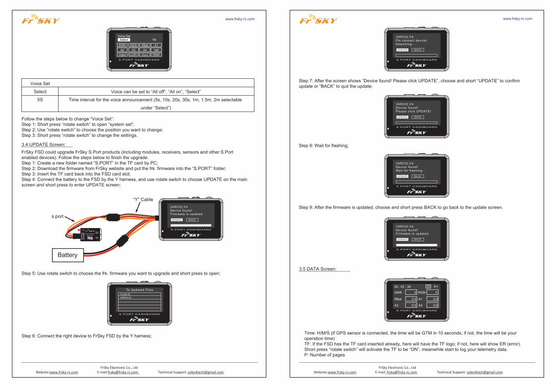
Follow the steps below to change the data names from page 1 to page 3:Step 1: Short press the rotate switchStep 2: Use the rotate switch to choose the position you want to changeStep 3: Short press the rotate switchStep 4: Use the rotate switch and find the data name you want and short press rotate switch to confirm.
Note: Data screen has 5 pages in total. Just enable the GPS sensor and Lipo Voltage Sensor on the SYSTEM screen to enable the page 4 and 5.
Page 4: GPS dataLatitu: Latitude (unit: degree)Longi: Longitude (unit: degree)Distance: Distance from your first positionto your flight position nowDate: Y/M/D
00 : 03 : 43 P4Lat i tu:Longi :Distance:Date:
0.00000.0000
02000-00-00
Page 5: Lipo Voltage Sensor dataTotal: Total voltage, cell number and cell voltage of all the batteries connected.
Total : 0.00 0s P50.000.000.000.000.000.00
0.000.000.000.000.000.00
DataSWRRSSIRBatA1 A2A3 A4A3_1 A4_1ValtVspdVcu1 Vcu2 Vcu3 Vcu4CUR1 CUR2 CUR3 CUR4TEM1 TEM2RPM1 RPM2 RPM3 RPM4FuelAltgSpdgCC1 CC2 CC3 CC4PWR1 PWR2 PWR3 PWR4CorsScurVol-
MeaningAntenna DetectionReceived Signal Strength IndicatorReceiver Battery VoltageAnalog Voltage (Receiver)Analog Voltage (S.port to UART Host)Analog voltage (S.port to UART Remote)Altitude of Variometer SensorVertical SpeedVoltage of Current SensorCurrent of Current SensorTemperatureRPMFuel LevelAltitude of GPSSpeed of GPSCurrent ConsumptionPower of Current SensorDirection of GPSSum Current of Current Sensorthe Lowest Voltage among all Cells
PhyID01NewPyID01
GNum01NewGNum01
Tip: FinishedSEND RESET
PhyIDphysical ID of the sensorNewPyIDnew physical ID you want to set for the sensorSENDRESETTip
GNumgroup number of the sensorNewGNumnew group number you want to set for the sensorsend your settings to the sensorreset your settings to defaultthe result of your settings
TIPS: Vcu, CUR, TEM1, RPM, CC, PWR have several data because of the different groups.
Follow the steps below to set “PhyID” and “GNum” for S.Port Sensors:Step 1: Use “rotate switch” to choose “IDSET”;Step 2: Use rotate switch to choose New PyID and/or New GNum and short press;Step 3: Set the number for the sensor and short press “rotate switch”;Step 4: Short press “SEND” and confirm “Tip” indicates “Finished”.
FrSky Sport DashboardFirmware Vers: v1.52Eeprom Vers: v0.3
FrSky Sport DashboardFirmware Vers: v1.52Eeprom Vers: v0.3
Follow the steps below to upgrade the FSD firmware:Step 1: Create a new folder named “Firmware” in the TF card by PC.Step 2: Download the firmware from FrSky website and put the .bin file into the “Firmware” folder.Step 3: Insert the TF card back into the FSD card slot.Step 4: Hold “Page” button while power on the FSD.Step 5: Use “rotate switch” to choose “YES” to reflash (or “NO” to quit) and short press “rotate switch” to confirm the upgrade.
FrSky Sport DashboardBoot Mode Ver-0.4Yes to Ref lash or NO to qui t?
Ready to upgrade
YES NO


![Torsional Response of Base-Isolated Structures Due to ... · superstructure varied from 0.1s to 1.2s, ... (up to 1/6 of the width). Nagarajaiah et al. [3] ... Jangid and Datta](https://img.pdfslide.us/doc/110x75/5ac0ce777f8b9a213f8c63dd/torsional-response-of-base-isolated-structures-due-to-varied-from-01s-to-12s.jpg)