Embed Size (px)
Citation preview

1
CAUTION: Do not scrape, rebabbit, or otherwise alter this product. Such action adversely affects bearing performance and may result in damage or destruction of equipment.
WARNING: Only qualified personnel familiar with the construction and operation of this equipment and the hazards involved should install, adjust, operate and/or service it. Read and understand this manual in its entirety before proceeding. Failure to observe this precaution could result in severe bodily injury or loss of life.
INSTALLATION:
The modular design of this bearing allows the use of multiple types of liners and two or more bore sizes in the same housing.
Types of Liners
‘S’ — Standard liner (fixed or free) has symmetrical thrust faces for bidirectional rotation.
‘T’ — High thrust, non-expansion (fixed) liner has tapered land thrust faces which MUST be oriented with shaft rotation as this type of thrust surface is unidirectional.
PRE-ASSEMBLY INSTRUCTIONS1.
Sleeve bearing performance is dependent on proper installation, lubrication and maintenance. Before assembling the bearing, read ALL instructions in this manual and follow all equipment manufacturers’ instructions.
DODGE SLEEVOIL PILLOW BLOCK NAMEPLATE
All SLEEVOIL housings and liners have nameplates attached to them. These nameplates have a six digit part number which fully identifies the housing and/or liner with any and all factory modifications to that part. Liner nameplate is pinned to the SLEEVOIL upper liner near an oil ring inspection hole. Housing nameplate is pinned to the housing foot parallel to the shaft.
WARNING: Because of the possible danger to person(s) or property from accidents which may result from the improper use of products, it is important that correct procedures be followed: Products must be used in accordance with the engineering information specified in the catalog. Proper installation, maintenance and operation procedures must be observed. The instructions in the instruction manuals must be followed. Inspections should be made as necessary to assure safe operation under prevailing conditions. Proper guards and other suitable safety devices or procedures as may be desirable or as may be specified in safety codes should be provided, and are neither provided by Baldor Electric Company nor are the responsibility of Baldor Electric Company. This unit and its associated equipment must be installed, adjusted and maintained by qualified personnel who are familiar with the construction and operation of all equipment in the system and the potential hazards involved. When risk to persons or property may be involved, a failsafe device must be an integral part of the driven equipment beyond the speed reducer output shaft.
Instruction Manual for DODGE SLEEVOIL RXT® Pillow Blocks
With External Circulating Oil LubricationThese instructions must be read thoroughly before installation or operation.
DODGE SLEEVOIL PILLOW BLOCK “MATCH MARKS”
HSG MATCH MARKS
LINER MATCH MARKS
All SLEEVOIL housing and liner halves have match marks permanently stamped above and below the joint. Use these match marks to ensure that parts stay paired and critical machined areas of an assembly are accurately maintained.
NOTE: Refer to applicable contract/assembly drawings to verify all parts are available prior to assembly.
Disassemble and thoroughly clean all parts of the pillow block. The installer is the last person to inspect all parts for fit, damage and cleanliness. Care MUST be taken to avoid contaminating the internal surfaces of the bearing. Housing caps and bases are match marked and MUST NOT be interchanged. Upper and lower liners are also match marked and MUST NOT be interchanged
NOTE: DO NOT DISCARD SHIMS AT JOINT. THEY ARE USED LATER FOR A CONTROLLED INTERFERENCE FIT OF LINER IN HOUSING. (See page 4)
CAUTION: Liner assembly has critical machined surfaces which are easily damaged. Use care when handling to protect these surfaces. Liner parts should be placed on a soft, CLEAN surface. Failure to observe these precautions may result in damage to or destruction of the equipment.
WARNING: Rust preventives and solvents can be toxic and/ or flammable. Follow directions and safety procedures recommended by their manufacturers. Failure to observe these precautions could result in bodily injury.
Check the mounting structure to ensure it is rigid, leveled, and well supported. Inspect the shaft to ensure it is smooth (32 micro-finish or better), free of burrs or rough spots and clean. Position the housing base on the pedestal in the position specified on the construction drawing. Do NOT tighten the base to the pedestal.
2
INSTALLATION OF LOWER LINER AND SHAFT2.
Apply oil to the spherical seats of the housing base and to the spherical seats of the lower liner half. The lower liner half is identified by its continuous babbitted bore surface; the upper liner half has one or two oil ring slot(s) in the center of the babbitted bore.
Set lower liner in housing base so spherical seats of liner are aligned with spherical seats of base. Horizontal split of liner MUST align with horizontal split of housing for anti-rotation pins in upper liner to engage holes in housing cap. Take care that circulating oil inlets and thermocouple holes in liner and housing base are aligned.
NOTE: ’T’ liner must be installed in direct relationship with shaft rotation.
Apply oil to the lower liner bore or to the shaft in liner area and CAREFULLY set the shaft in place, taking care not to damage the babbitted surface.
CIRC. OIL INLET HOLE
THERMOCOUPLE HOLE
2.1 LABYRINTH SEAL
Attach lower half of each oil seal to housing base. Check possible alignment of oil seal by visually noting an equal clearance between seal and shaft at each end of the housing. The seals can be adjusted somewhat but MUST NOT contact the shaft at any point.
CLEARANCE BETWEENSHAFT AND SEAL
SHAFT
LABYRINTH SEAL
Alignment of pillow block should be accurate since the self-aligning feature of the bearing is to compensate for normal shaft deflection.
Re-shim pillow block, if necessary. Always shim under the bearing pedestal where possible; otherwise, use full length shims under base of pillow block.
NOTE: Remove lower half of each labyrinth seal from housing after this preliminary alignment to avoid damaging the lip of the labyrinth.
SEAL LIP
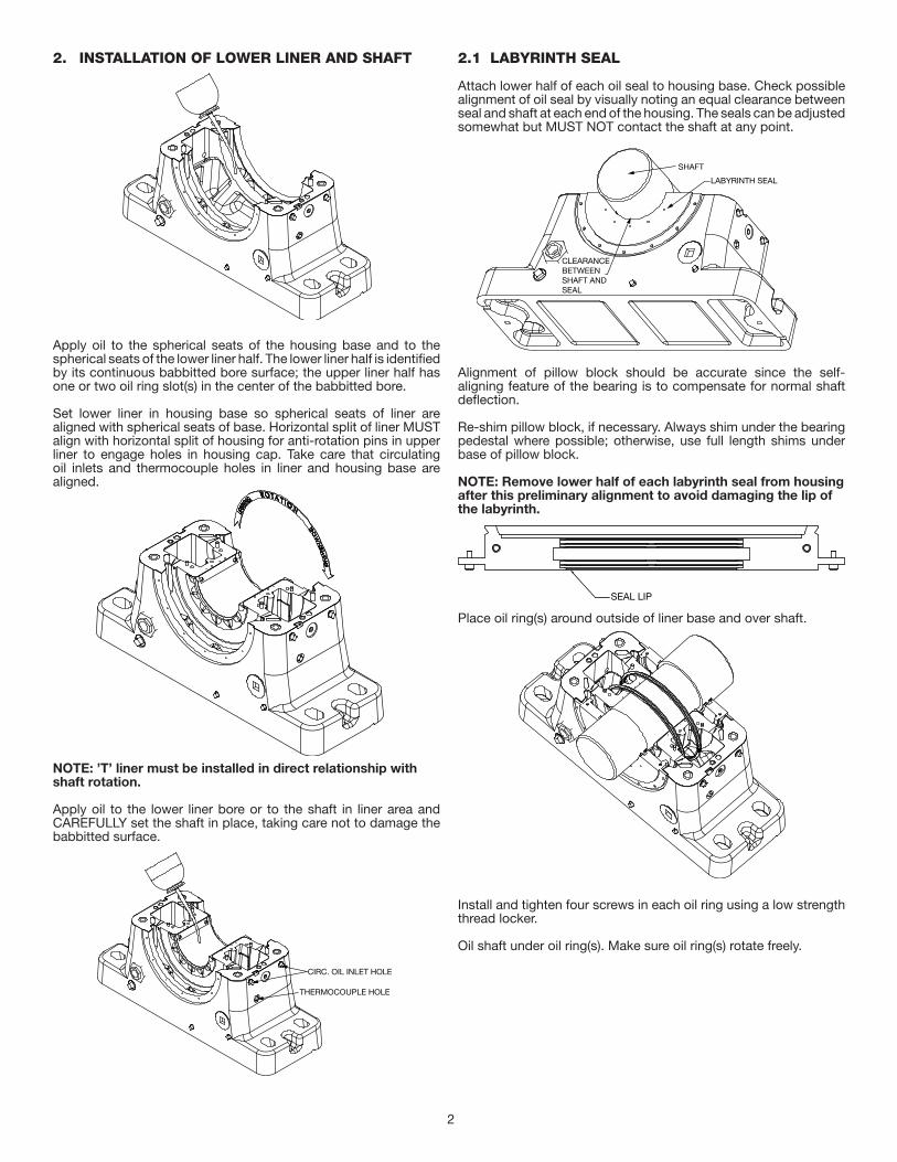
Place oil ring(s) around outside of liner base and over shaft.
Install and tighten four screws in each oil ring using a low strength thread locker.
Oil shaft under oil ring(s). Make sure oil ring(s) rotate freely.
3
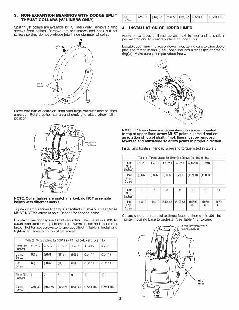
NON-EXPANSION BEARINGS WITH DODGE SPLIT 3. THRUST COLLARS (‘S’ LINERS ONLY)
Split thrust collars are available for ‘S’ liners only. Remove clamp screws from collars. Remove jam set screws and back out set screws so they do not protrude into inside diameter of collar.
MATCHMARKS
PART NO.
Place one half of collar on shaft with large chamfer next to shaft shoulder. Rotate collar half around shaft and place other half in position.
LARGE CHAMFERNEXT TOSHAFT SHOULDER
NOTE: Collar halves are match marked; do NOT assemble halves with different marks.
Tighten clamp screws to torque specified in Table 2. Collar faces MUST NOT be offset at split. Repeat for second collar.
Locate collars tight against shaft shoulders. This will allow 0.015 to 0.035 inch total running clearance between collars and liner thrust faces. Tighten set screws to torque specified in Table 2. Install and tighten jam screws on top of set screws.
Table 2 - Torque Values for DODGE Split Thrust Collars (in.-lbs.) ft.-lbs.
Shaft Size(inches)
2-15/16 3-7/16 3-15/16 4-7/16 4-15/16 5-7/16
Clamp Screw
(96) 8 (96) 8 (96) 8 (96) 8 (204) 17 (204) 17
Set Screw
(60) 5 (60) 5 (60) 5 (60) 5 (132) 11 (132) 11
Shaft Size(inches)
6 7 8 9 10 12
Clamp Screw
(360) 30 (360) 30 (900) 75 (900) 75 (1800) 150 (1800) 150
Set Screw
(264) 22 (264) 22 (264) 22 (264) 22 (1320) 110 (1320) 110
INSTALLATION OF UPPER LINER4.
Apply oil to faces of thrust collars next to liner and to shaft in journal area and to journal surface of upper liner.
Locate upper liner in place on lower liner, taking care to align dowel pins and match marks. (The upper liner has a recess(es) for the oil ring(s)). Make sure oil ring(s) rotate freely.
NOTE: ‘T’ liners have a rotation direction arrow mounted to top of upper liner; arrow MUST point in same direction as rotation of top of shaft. If not, liner must be removed, reversed and reinstalled so arrow points in proper direction.
Install and tighten liner cap screws to torque listed in table 3.
Table 3 - Torque Values for Liner Cap Screws (in.-lbs.) ft.-lbs.
Shaft Size
(inches)
2-15/16 3-7/16 3-15/16 4-7/16 4-15/16 5-7/16
Liner Cap
Screw
(58) 5 (58) 5 (58) 5 (58) 5 (114) 10 (114) 10
Shaft Size
(inches)
6 7 8 9 10 12 14
Liner Cap
Screw
(114) 10 (114) 10 (510) 43 (510) 43 (1050) 88
(1050) 88
(1050) 88
Collars should run parallel to thrust faces of liner within .001 in. Tighten housing base to pedestal. See Table 4 for torque.
MATCHMARKS
CHECK LINER THRUST FACE &COLLAR CLEARANCE
4
Table 4 - Torque Value for Housing Hardware (in.-lbs.) ft.-lbs.
Housing Size
3 4 5 6 8 10
Housing to
Pedestal Bolts
(2000)167
(3600)300
(4600)383
(8400)700
(11500)958
(15000)1250
Housing to
Cap Bolts
(1560)130
(2280)190
(2280)190
(2280)190
(3240)270
(3240)270
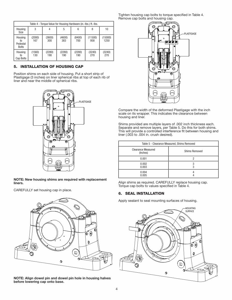
INSTALLATION OF HOUSING CAP5.
Position shims on each side of housing. Put a short strip of Plastigage (3 inches) on liner spherical ribs at top of each rib of liner and near the middle of spherical ribs.
PLASTIGAGE
NOTE: New housing shims are required with replacement liners.
CAREFULLY set housing cap in place.
NOTE: Align dowel pin and dowel pin hole in housing halves before lowering cap onto base.
Tighten housing cap bolts to torque specified in Table 4.Remove cap bolts and housing cap.
PLASTIGAGE
Compare the width of the deformed Plastigage with the inch scale on its wrapper. This indicates the clearance between housing and liner.
Shims provided are multiple layers of .002 inch thickness each. Separate and remove layers, per Table 5. Do this for both shims. This will provide a controlled interference fit between housing and liner (.003 to .004 in. crush desired).
Table 5 - Clearance Measured, Shims Removed
Clearance Measured (Inches) Shims Removed
0.001 2
0.0020.003
33
0.0040.005
44
Align shims as required. CAREFULLY replace housing cap. Torque cap bolts to values specified in Table 4.
SEAL INSTALLATION6.
Apply sealant to seal mounting surfaces of housing.
MOUNTINGSURFACE
5
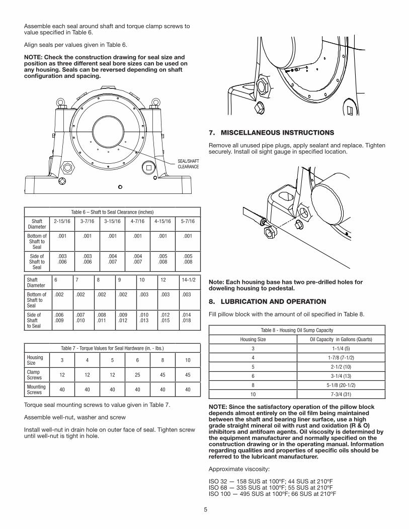
Assemble each seal around shaft and torque clamp screws to value specified in Table 6.
Align seals per values given in Table 6.
NOTE: Check the construction drawing for seal size and position as three different seal bore sizes can be used on any housing. Seals can be reversed depending on shaft configuration and spacing.
SEAL/SHAFTCLEARANCE
Table 6 – Shaft to Seal Clearance (inches)
Shaft Diameter
2-15/16 3-7/16 3-15/16 4-7/16 4-15/16 5-7/16
Bottom of Shaft to
Seal
.001 .001 .001 .001 .001 .001
Side of Shaft to
Seal
.003
.006.003.006
.004
.007.004.007
.005
.008.005.008
Shaft Diameter
6 7 8 9 10 12 14-1/2
Bottom of Shaft to Seal
.002 .002 .002 .002 .003 .003 .003
Side of Shaftto Seal
.006
.009.007.010
.008
.011.009.012
.010
.013.012.015
.014
.018
Table 7 - Torque Values for Seal Hardware (in. - lbs.)
Housing Size 3 4 5 6 8 10
Clamp Screws 12 12 12 25 45 45
Mounting Screws 40 40 40 40 40 40
Torque seal mounting screws to value given in Table 7.
Assemble well-nut, washer and screw
Install well-nut in drain hole on outer face of seal. Tighten screw until well-nut is tight in hole.
MISCELLANEOUS INSTRUCTIONS7.
Remove all unused pipe plugs, apply sealant and replace. Tighten securely. Install oil sight gauge in specified location.
Note: Each housing base has two pre-drilled holes for doweling housing to pedestal.
LUBRICATION AND OPERATION8.
Fill pillow block with the amount of oil specified in Table 8.
Table 8 - Housing Oil Sump Capacity
Housing Size Oil Capacity in Gallons (Quarts)
3 1-1/4 (5)
4 1-7/8 (7-1/2)
5 2-1/2 (10)
6 3-1/4 (13)
8 5-1/8 (20-1/2)
10 7-3/4 (31)
NOTE: Since the satisfactory operation of the pillow block depends almost entirely on the oil film being maintained between the shaft and bearing liner surface, use a high grade straight mineral oil with rust and oxidation (R & O) inhibitors and antifoam agents. Oil viscosity is determined by the equipment manufacturer and normally specified on the construction drawing or in the operating manual. Information regarding qualities and properties of specific oils should be referred to the lubricant manufacturer.
Approximate viscosity:
ISO 32 — 158 SUS at 100ºF; 44 SUS at 210ºFISO 68 — 335 SUS at 100ºF; 55 SUS at 210ºFISO 100 — 495 SUS at 100ºF; 66 SUS at 210ºF
6
8.1 CIRCULATING OIL
When pillow block is arranged for circulating oil, the pressurized oil is delivered to the 2 openings on the downswing side of the pillow block when the radial load is directed into the base and the upswing side when the radial load is directed into the cap. Inlet lines should have flow control valves and an oil flow indicator. Each inlet should receive an equal amount of oil.
Drain piping should be vented and of adequate size to drain oil from the bearing at the specified flow rate. The housing drain must be directed straight down into a return drain sloping away at a 15º or greater angle. Drain lines connect to the pillow block in the location used for the oil level gauge. Use both drains for more effective draining. The oiling system must have a means of filtering the oil to remove any contaminating particles. (DODGE recommends a 25 micron filter or better.) Use of both drain lines is recommended for non-expansion bearing. The circulating oil unit should be ran a minimum of 2 hours to clean the lines. Filters are to be changed and the unit restarted for another 2 hours. Check filter again and if clean proceed with fan start-up. Make sure lube unit is running prior to starting the fan.
NOTE: All plumbing should be cleaned and flushed before being connected to the pillow block. These systems should be tested before the bearing is put into operation.
NOTE: Bearings should NOT be stored outdoors before installation. For extended or outdoor storage, contact equipment manufacturer for special precautions against corrosion.
NOTE: Bearings (and shafts) allowed to set idle for extended periods after being run MUST be protected against corrosion. If the unit cannot be run for several minutes at least once a week, consult equipment manufacturer for special lubrication instructions.
8.2 Temperature
The bearing temperature will increase after start-up until its normal operating level is reached. Some fluctuation due to ambient temperature change is normal, but a drastic change MUST be investigated. Normal running temperature should not exceed 180ºF. (Check with equipment manufacturer to see if another operating temperature has been specified.) Low ambient and operating temperatures can be as harmful to the bearing as high temperatures. A heater and thermoswitch is required for such applications.
8.3 Minimum Temperature at Start-Up:
ISO 32 oil, 60ºFISO 68 oil, 85ºFISO 100 oil, 100ºF
8.4 Vibration:
Any significant vibration or imbalance MUST be corrected. Check with equipment manufacturer for acceptable conditions.
7
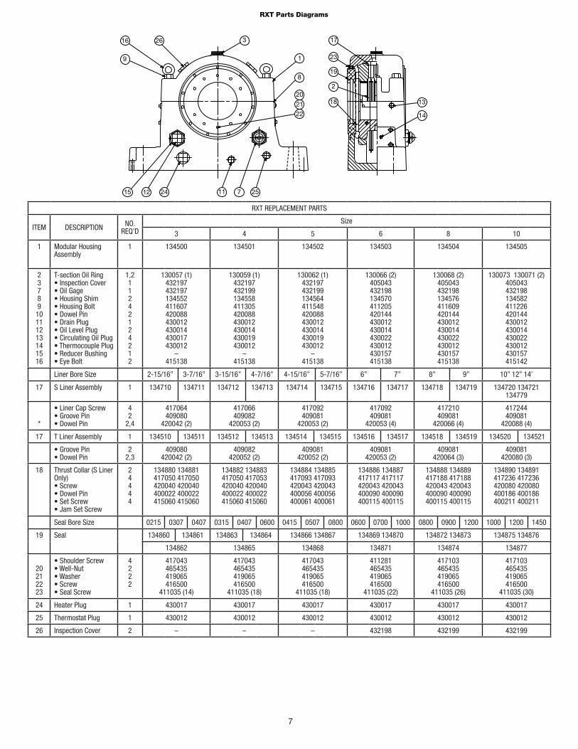
RXT Parts Diagrams
26 316
9
15 12 24 11 7 25
18
2
22
21
20
8
1
17
23
19
13
14
RXT REPLACEMENT PARTS
ITEM DESCRIPTION NO. REQ’D
Size
3 4 5 6 8 10
1 Modular Housing Assembly
1 134500
134501 134502
134503
134504
134505
23789
10111213141516
T-section Oil Ring• Inspection Cover• Oil Gage• Housing Shim• Housing Bolt• Dowel Pin• Drain Plug• Oil Level Plug• Circulating Oil Plug• Thermocouple Plug• Reducer Bushing• Eye Bolt
1,211242124212
130057 (1)432197432197134552411607420088430012430014430017 430012
–415138
130059 (1)432197432199134558411305420088430012430014430019430012
–415138
130062 (1)432197432199134564411548420088430012430014430019 430012
–415138
130066 (2)405043432198134570411205420144430012430014430022430012430157415138
130068 (2)405043432198134576411609420144430012430014430022430012430157415138
130073 130071 (2)405043432198134582411226420144430012430014430022430012430157415142
Liner Bore Size 2-15/16” 3-7/16” 3-15/16” 4-7/16” 4-15/16” 5-7/16” 6” 7” 8” 9” 10” 12” 14’
17 S Liner Assembly 1 134710 134711 134712 134713 134714 134715 134716 134717 134718 134719 134720 134721 134779
*
• Liner Cap Screw• Groove Pin• Dowel Pin
42
2,4
417064409080
420042 (2)
417066409082
420053 (2)
417092409081
420053 (2)
417092409081
420053 (4)
417210409081
420066 (4)
417244409081
420088 (4)
17 T Liner Assembly 1 134510 134511 134512 134513 134514 134515 134516 134517 134518 134519 134520 134521
• Groove Pin• Dowel Pin
22,3
409080420042 (2)
409082420052 (2)
409081420052 (2)
409081420053 (2)
409081420064 (3)
409081420080 (3)
18 Thrust Collar (S Liner Only)• Screw• Dowel Pin• Set Screw• Jam Set Screw
24444
134880 134881417050 417050 420040 420040400022 400022415060 415060
134882 134883417050 417053420040 420040400022 400022415060 415060
134884 134885417093 417093420043 420043400056 400056400061 400061
134886 134887417117 417117420043 420043400090 400090400115 400115
134888 134889417188 417188420043 420043400090 400090400115 400115
134890 134891417236 417236420080 420080400186 400186400211 400211
Seal Bore Size 0215 0307 0407 0315 0407 0600 0415 0507 0800 0600 0700 1000 0800 0900 1200 1000 1200 1450
19 Seal 134860 134861 134863 134864 134866 134867 134869 134870 134872 134873 134875 134876
134862 134865 134868 134871 134874 134877
20212223
• Shoulder Screw• Well-Nut• Washer• Screw• Seal Screw
4222
417043465435419065416500
411035 (14)
417043465435419065416500
411035 (18)
417043465435419065416500
411035 (18)
411281465435419065416500
411035 (22)
417103465435419065416500
411035 (26)
417103465435419065416500
411035 (30)
24 Heater Plug 1 430017 430017 430017 430017 430017 430017
25 Thermostat Plug 1 430012 430012 430012 430012 430012 430012
26 Inspection Cover 2 – – – 432198 432199 432199
8
23
7(4x)3
1(2x)
27(4x) 2(2x)
5(2x)4
25(4x)
26
22(2x) 3420
19
24
2921
23 30
33
12
17(2x)
11(4x)
10(2x)
8
2814
13
16
15
18
32
31
9(4x)
6
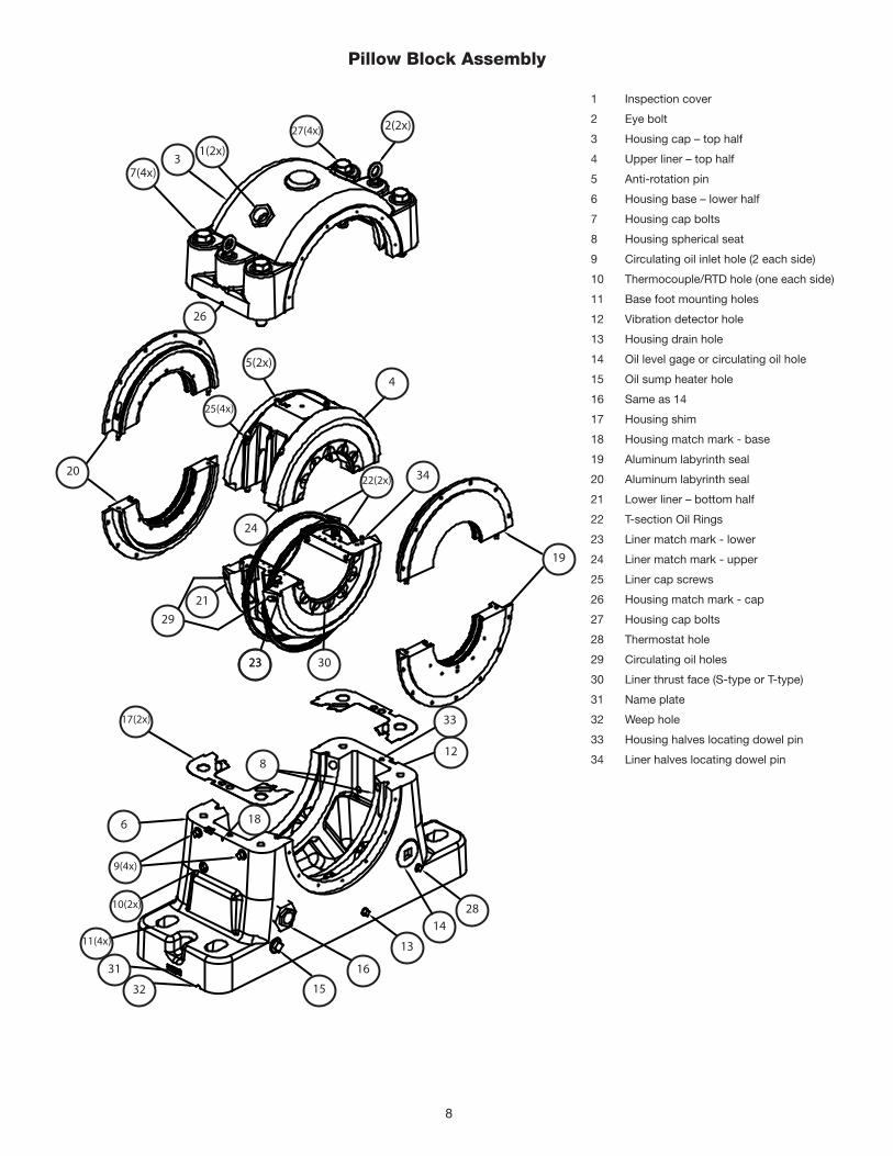
1 Inspection cover
2 Eye bolt
3 Housing cap – top half
4 Upper liner – top half
5 Anti-rotation pin
6 Housing base – lower half
7 Housing cap bolts
8 Housing spherical seat
9 Circulating oil inlet hole (2 each side)
10 Thermocouple/RTD hole (one each side)
11 Base foot mounting holes
12 Vibration detector hole
13 Housing drain hole
14 Oil level gage or circulating oil hole
15 Oil sump heater hole
16 Same as 14
17 Housing shim
18 Housing match mark - base
19 Aluminum labyrinth seal
20 Aluminum labyrinth seal
21 Lower liner – bottom half
22 T-section Oil Rings
23 Liner match mark - lower
24 Liner match mark - upper
25 Liner cap screws
26 Housing match mark - cap
27 Housing cap bolts
28 Thermostat hole
29 Circulating oil holes
30 Liner thrust face (S-type or T-type)
31 Name plate
32 Weep hole
33 Housing halves locating dowel pin
34 Liner halves locating dowel pin
Pillow Block Assembly
9
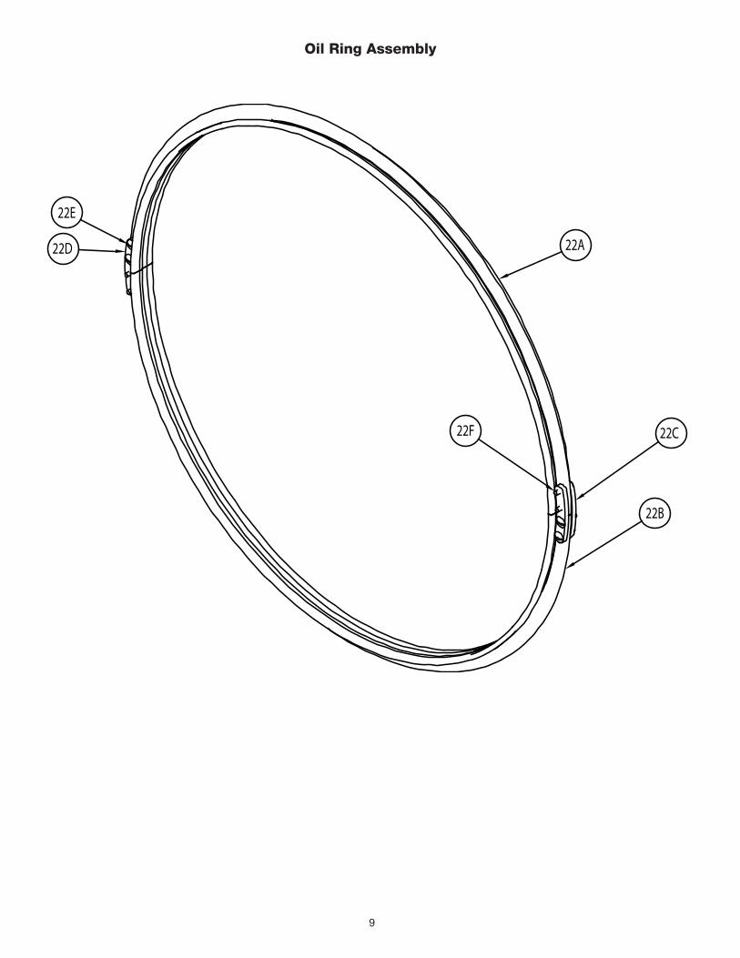
Oil Ring Assembly
22A
22B
22C
22D
22E
22F
10
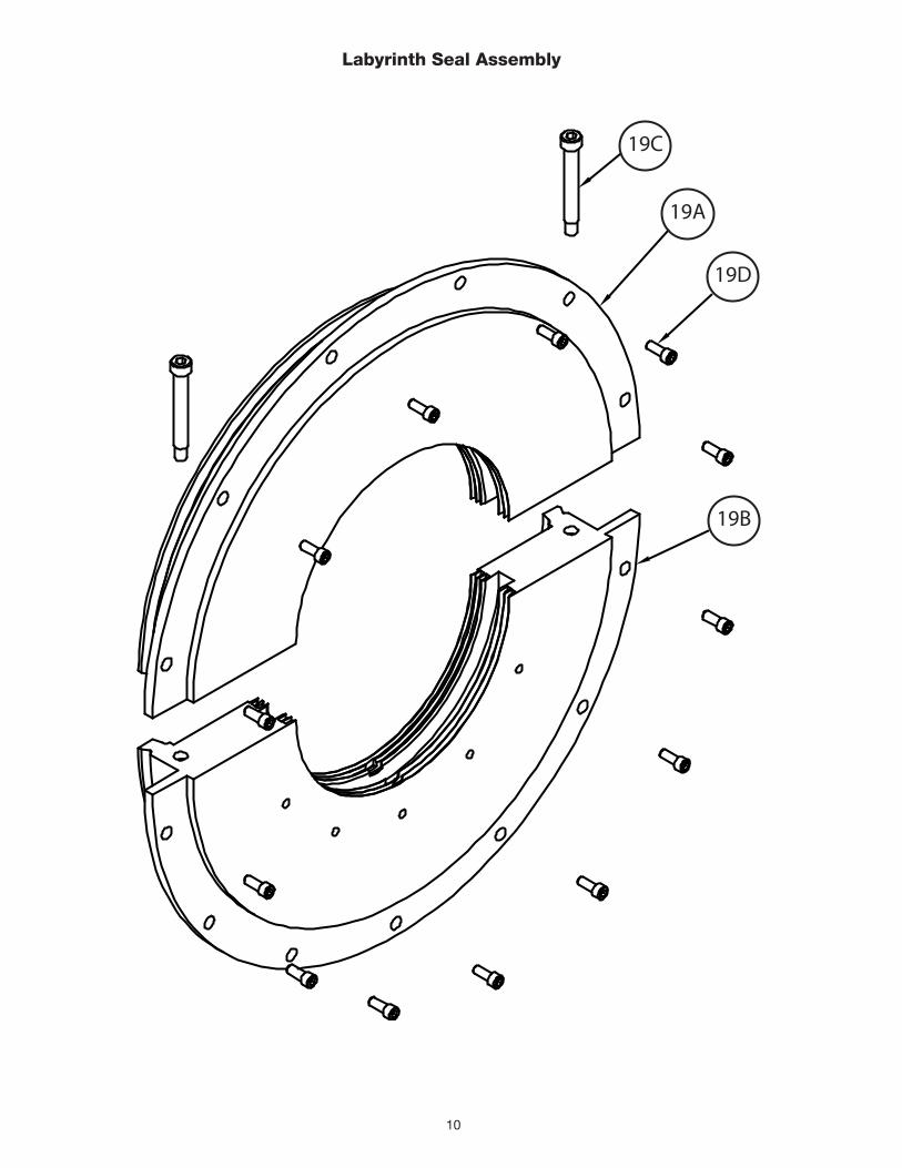
Labyrinth Seal Assembly
19C
19A
19D
19B
11
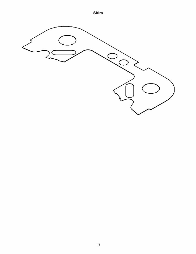
Shim

World Headquarters
P.O. Box 2400, Fort Smith, AR 72902-2400 U.S.A., Ph: (1) 479.646.4711, Fax (1) 479.648.5792, International Fax (1) 479.648.5895
Dodge Product Support
6040 Ponders Court, Greenville, SC 29615-4617 U.S.A., Ph: (1) 864.297.4800, Fax: (1) 864.281.2433
www.baldor.com
All Rights Reserved. Printed in USA.2/10 PRINTSHOP 200
© Baldor Electric CompanyMN3065 *3065-0210*