Embed Size (px)
Citation preview

DIGITAL INDICATOR
CSD-903-EX
Instruction Manual
EN294-1492-M

I
FOREWORD
Thank you very much for your purchasing the digital Indicator CSD-903-EX.
This manual is provided to explain installation procedures and check points in operation. We
would like you to read through this instruction manual with much care for the best use of our
product to avoid malfunctions.
We also would like you to deliver the manual to end user surely to keep it at hand.
Marks and references described in this manual
The following marks are placed for the matters that indicate “Don’t do this”, “Caution”, and “For
reference”. Please be sure to read following descriptions with marks.
Warning
When you are operating the instrument, you have to pay cautions or restrictions related with this description. Be sure to read to prevent from malfunction.
Caution
Descriptions that may cause injury or physical damage to operators and such as occurrences of physical damage.
When you are operating the instrument, you have to pay cautions or restrictions related with this description. Be sure to read to prevent from malfunction.

II
For safe operation
Be sure to read this manual before operation.
1. Location of installation
Caution
Use the Instrument under the following conditions.
● Environmental temperature : -10 ℃ ~ 50 ℃ (Preservation : -20 ℃ ~ 60 ℃)
※The temperature span of JIS B 7611-2 conformity is -10 ℃ ~ 40 ℃.
● Environmental humidity : Less than 85 % R.H.(Non condensing)
Caution
Do not install the Instrument in following places. It may cause damage to the Instrument.
(1) Place to be avoided.
● Places exposed to direct sunlight and/or places in the high temperature.
● Places in a high humid area.
● Places where the instrument is directly affected by vibrations or mechanical shocks.
● Environments containing of corrosive gas or salt, etc.
● Environments with rapid change in temperature and/or humidity.
● Near the devices which generate magnetism or electromagnetic waves.
● Environments vulnerable to radioactivity or radioactivity rays.
● Environments where chemical reaction may take place such a laboratory.

III
(2) Installing the Instrument
Caution
Please secure and set up the spaces between CSD-903 and the devices.
Followings are the dimensions of the Instrument and for environmental spaces required:
Front Side
Rear dimension Panel cut
unit: mm
The side view when BCD connector is installed. (The I/O connector for external control attached is the same dimension as a BCD connector.)
unit: mm
Control I/O Connector
BCD out connector (Option)
IV
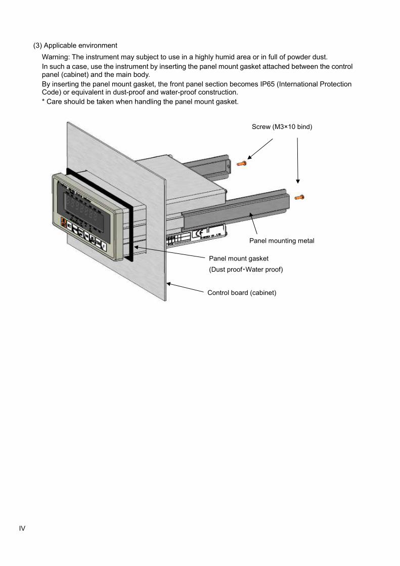
(3) Applicable environment
Warning: The instrument may subject to use in a highly humid area or in full of powder dust.
In such a case, use the instrument by inserting the panel mount gasket attached between the control panel (cabinet) and the main body.
By inserting the panel mount gasket, the front panel section becomes IP65 (International Protection Code) or equivalent in dust-proof and water-proof construction.
* Care should be taken when handling the panel mount gasket.
Screw (M3×10 bind)
Panel mounting metal
Panel mount gasket
(Dust proof・Water proof)
Control board (cabinet)

V
2. Power supply
Warning
Be sure to check that power supply is OFF when installing each cable. If an operator works with power ON, he/she may have an electric shock or the instrument may be destroyed.
Warning
Before supplying power, check the indication of power voltage/specifications to be identical with supplied power. If they are not identical, contact with us. Without checking the above, operation may cause damage to the instrument or electric shock.
Caution
Be sure to ground a grounding wire. If a grounding wire is not grounded, it may cause malfunction of the instrument or an electric shock to an operator.
3. Instructions for use
Caution
Before using a new instrument, or when exchanging a strain gage applied transducer for a new one, be sure to make calibration. If neglected, it may cause incorrect results in measurement or malfunction in the instrument and moreover may cause damage to peripheral equipments. When similar trouble occurs after calibration, be sure to make calibration again, even if calibration has completed.
Caution
When using the instrument, check that wires are connected properly. If neglected, correct measurement cannot be obtained and it may cause malfunction in the instrument or cause damage to peripheral devices or a critical accident.
Caution
Improper change of setting during operation may cause incorrect measurement or malfunction, or cause damage to peripheral equipments.
Caution
Do not give the instrument such a shock as throwing something at it. It may cause damage or destroy electrical circuits and even have loose resistance to environment or operability.
Caution
Do not remove the cover of the case of the instrument, nor peel off the panel sheet nor take the instrument into pieces. If neglected, it may cause damage to the case and the panel sheet and even have the possibility of damage to resist to environments or operational performances.
At the time of shipment from the factory, the instrument has been plated with a clear sheet on the panel sheet for protective purpose. In case of application, use the instrument after removing the clear sheet first.
Do not push the panel sheet on the instrument with the excessive strong force nor push it with sharp edge object such as a driver. If neglected, it may cause damage to the panel switch and even have the possibility of damage to resist to environments or operational performances.
VI
4. Conformity standard
This instrument has suited the following standard.
EN61326:2013
[Electrical equipment for measurement, control, and laboratory use - EMC requirements]
[Immunity test requirements for equipment intended for use in industrial locations]
EN61010-1:2010
[Safety requirements for electrical equipment for measurement, control and laboratory use
- Part 1:General requirement]
EN50581:2012
"Technical documentation for the assessment of electrical and electronic products with respect to the restriction of hazardous substances" (RoHS Directive)
Annex C (Performance level H) of JIS B 7611-2:2015
[Non-automatic weighing instruments – Metrological and technical requirements and tests
- Part 2:Measuring instruments used in transaction or certification]
Caution
The instrument with the software ver.2.100 or later conforms to the JIS standard.
Caution
Please observe the following conditions strictly when this instrument suits the below if neglected, it may not conform to the above standard.
(1) Shield processing
- Use the shielded cable other than the power cable.
- Refer to relative notes, for method of shielding process.
(2) Grounding
- The ground of this instrument shall apply the individual ground by using the protective ground terminal.
VII
Caution
Please observe the following conditions strictly when this instrument suits the JIS standard. If neglected, there is a possibility of not suiting the above-mentioned standard.
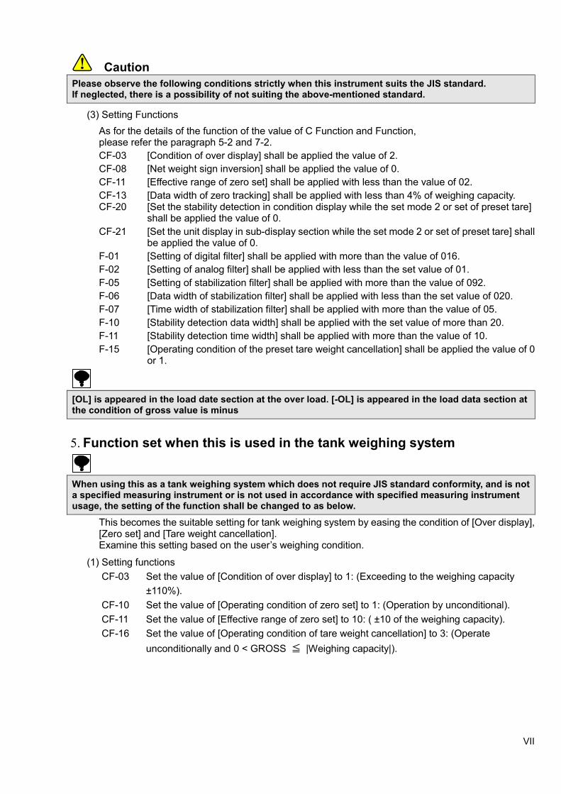
(3) Setting Functions
As for the details of the function of the value of C Function and Function, please refer the paragraph 5-2 and 7-2.
CF-03 [Condition of over display] shall be applied the value of 2.
CF-08 [Net weight sign inversion] shall be applied the value of 0.
CF-11 [Effective range of zero set] shall be applied with less than the value of 02.
CF-13 [Data width of zero tracking] shall be applied with less than 4% of weighing capacity. CF-20 [Set the stability detection in condition display while the set mode 2 or set of preset tare] shall be applied the value of 0.
CF-21 [Set the unit display in sub-display section while the set mode 2 or set of preset tare] shall be applied the value of 0.
F-01 [Setting of digital filter] shall be applied with more than the value of 016.
F-02 [Setting of analog filter] shall be applied with less than the set value of 01.
F-05 [Setting of stabilization filter] shall be applied with more than the value of 092.
F-06 [Data width of stabilization filter] shall be applied with less than the set value of 020.
F-07 [Time width of stabilization filter] shall be applied with more than the value of 05.
F-10 [Stability detection data width] shall be applied with the set value of more than 20.
F-11 [Stability detection time width] shall be applied with more than the value of 10.
F-15 [Operating condition of the preset tare weight cancellation] shall be applied the value of 0 or 1.
[OL] is appeared in the load date section at the over load. [-OL] is appeared in the load data section at the condition of gross value is minus
5. Function set when this is used in the tank weighing system
When using this as a tank weighing system which does not require JIS standard conformity, and is not a specified measuring instrument or is not used in accordance with specified measuring instrument usage, the setting of the function shall be changed to as below.
This becomes the suitable setting for tank weighing system by easing the condition of [Over display], [Zero set] and [Tare weight cancellation]. Examine this setting based on the user’s weighing condition.
(1) Setting functions
CF-03 Set the value of [Condition of over display] to 1: (Exceeding to the weighing capacity
±110%).
CF-10 Set the value of [Operating condition of zero set] to 1: (Operation by unconditional).
CF-11 Set the value of [Effective range of zero set] to 10: ( ±10 of the weighing capacity).
CF-16 Set the value of [Operating condition of tare weight cancellation] to 3: (Operate
unconditionally and 0 < GROSS ≦ |Weighing capacity|).

VIII
Divisional history
Data Manual NO. Revision reason(content)
2010/10 DRW. NO. EN294-1492 First edition VER. 1. 000
2011/2 DRW. NO. EN294-1492A
Due to ECN No.FN10-02182A,FN11-02001 ROM Ver.2.100 or later - Addition – Preface 4.[JIS B 7611-2 : 2009] conformity standard. 4-3-1. addition of procedure 6-5. [System using the zener barrier] is added. 6-11. [Setting while set mode 2 or set of preset tare] 6-11-1.[Operation for stability detection] 6-11-2.[Operation for unit display in sub-display section] Clause 6 and item number correction 12.[EzCTS mode] is added to [Check mode]. 12-2.[EzCTS mode] Clause 12 and item number correction 16-3-12.[Reading out ROM version] is added command. 25.[CF-20] or [CF-21] is added to [Setting table for functions]. Additional correction of contents. - Correction- Preface 4.[EN61326:2009] → [EN61326:2006] 14-3-4.[Delay time of RS-485 return data] 16-3-10.[DE-9S-N(JAE)] → [DE-9S-NR by JAE or equivalent.] 18-4.Power consumption [Approx. 8 VA] → [Approx 10 VA]
2011/10 DRW. NO. EN294-1492B
Due to ECN No.FN11-02123 ROM Ver.2.200 or later - Correction- Preface 1. Change picture of front view and panel mounting view. 9. Correct the numbers of reference clause and mistakes. 9-3-2. Correct the drawing of simple comparison discharging mode. 16-1-5. Correct the graph for scaling of analog output. - Addition- 1-1. Add the contents of the each function for condition display section 2. 9-2-1. Add the contents of condition display section in the measurement comparison value 1 setting mode. - Deletion-
16-2-9. Delete the notes sentence・If set value of CF-03 is 2 and
fross value is minus, BCD output shall be data over condition.
2011/12 DRW. NO. EN294-1492C
Due to ECN No.FN11-02123 - Deletion-
6-9-1. Delete the notes sentence・The tare weight cancellation is
not accepted when gross value is below the zero.
2012/12 DRW. NO. EN294-1492-D
Due to ECN No.FN12-02088 -Correction- Change of Minebea’s Logo. - Addition- 2-3. Add the applicable connector. 2-4. Add the applicable connector and note. 2-5. Add the applicable connector and note.
IX
Data Manual NO. Revision reason(content)
2012/12 DRW. NO. EN294-1492-D
Due to ECN No.FN12-02095 -Correction- 7-2., 8-5., 16-3-12.(12) change the explanation of key lock. 7-2., 16-2-2., 16-3-12(12) change the explanation of stream mode. 16-3-14. Correct the explanation of procedure for communications. -Addition- 4-3-8. Add the note. 16-3-14. Add the explanation for calibration procedure. 6-2., 7-1., 8-14., 9-2-1., 9-2-2., 9-8., 10-18., 11-3., 16-2-13(9), (10), (12). Add the note,and correction of error in writing. Due to ECN NO.FN12-02097-A -Correction- 1-1. Change the clause in the explanation of ZERO from [Gross value or Net value] to [displayed]. 4-3-6. Change the displayed number of dight for load cell output voltage at zero calibration. 4-3-7. Change the displayed number of digit for load cell output voltage at span calibration. 5-2. Change the number of digit for CF-93. and CF-94. 12-7. Change the number of digit for load cell output voltage. 16-3-3. Change the explanation of when RS-422/485 is used. 16-3-4. Change the explanation, title and note. 16-3-12. Command list for reading and writing the set value. 16-3-13. (1)Change explanation title. (2)Change explanation title. -Addition- 7-2. Add F-18/48/49. Add the set value of F-19/47. Add the contents of item of F-41. 8-9. Add the target of hold to holding explanation. 8-9-2. Add the detailed information of holding target. 8-10-1. Add the selection item of sub display. 14-3-1. Add the stream mode and note. 14-3-6. Add the explanation of output target in stream mode. 16-3-12. Add F-17., F-18., F-48., F-49., to the command list for reading and writing the set value. Add the set value 9 ~ 15 of F-19 and 2 of F-47. 16-3-14. (7) 2) Add the registration command for zero of the fifth decimal point digit. (10) 2) Add the registration command for span of the fifth decimal point digit. 25. Add the F-18.,F-48., and F-49 to the table of function settting. Add the setting of 9 ~ 15 to the setting table of sub display (F-19). Due to ECN No.FN12-02119 -Addition- 16-1-1. Add the resolution. 16-1-2. Add the resolution. 18-3. Add the resolution.
2013/05 DRW. NO. EN294-1492-E Due to ECN No.FN13-02078 - Addition- 15. Add a sentence to the configuration table.
X
Data Manual NO. Revision reason(content)
2015/07 DRW. NO. EN294-1492-F
Due to ECN NO.FN15-02117 < Correction > Cover : Change [MINEBEA] logo
Foreword, Ⅶ. Change the setting amount for operating condition
of Preset tare weight cancellation 7-2., 8-10., 16-3-12. Change the combination including [Brand]. 8-11. Change the display range of accumulating operation. 8-11-2. Correct the note of accumulating operation. 25.Setting table for functions <Additional>
Foreword, Ⅶ. Add the setting value of net weight sign inversion.
3-1. Add the accumulation display mode. 5-2., 6-6.Add the net weight sign inversion and explanation. 7-2. Add the preset tare weight cancellation operating condition, comparator brand setting target, operating mode of RS-232C interface, brand switch target, brand number, and external control input. 8-7-3. Add the explanation of net weight offset operation. 8-11. Add the explanation of accumulation value clear and accumulation time clear. 8-12. Add the explanation of brand switch target. 8-14. Add all brand accumulation clear, brand-1, brand-2, and brand-4. 9-2. Add the explanation of brand number setting method. 9-5., 9-6. Add the explanation of set value of 4-steps comparator mode. 9-9. Add the batch/discharge brand setting and all brand accumulation clear. 10-11. Add the explanation of batch/discharge brand setting target. 14-3. Add the explanation of operating mode. 15. Add the explanation of command and calibration by communication. 16-3-12. Add the accumulation amount (10 digits), effective brand number, setting brand number, comparator brand setting target, all brand accumulation clear, RS-232C operating mode external control input.
2016/05 DRW.NO. EN294-1492-G
Due to ECN FN16-02057 - Deletion- Delete ‘Minebea Co., LTD. Measuring Components Business Unit’ from the front cover.
2017/08 DRW.NO. EN294-1492-H Due to ECN FN17-02017
・Delete the company name in the contents.
2018/01 DRW. NO. EN294-1492-I
Due to ECN FN17-02066C
Add and correct the applicable standard.
- Add [EN50581・2012]
- Correct from [EN61326-1:2006] to [EN61326-1:2013]
- Correct from [EN61010-1:2001] to [EN61010-1:2010]
- Correct from [JIS B 7611-2:2009] to [JIS B 7611-2:2015]

XI
Data Manual NO. Revision reason(content)
2018/02 DRW. NO. EN294-1492-J
Due to ECN No.FN18-02017
< Correction >
Change the clause in 2-3. Note column as follows;
from (・Refer to [8-13-1. Setting ~.) to (・Refer to [8-14-1. Setting ~.)
from (・Refer to [8-13-2. Setting ~.) to (・Refer to [8-14-2. Setting ~.)
2018/12 DRW. NO. EN294-1492-K
Due to ECN No.FN18-02080
-Addition-
・5.Function set when this is used in the tank weighing system.
Contents
・5.Function set when this is used in the tank weighing system.
2019/05 DRW. NO. EN294-1492-L
Due to ECN FN19-0159
2-3. Correction
The following statement is added to the note of the external
control input.
・Do not assign the same set value to multiple PIN numbers.
This instrument does not work properly.
2019/08 DRW. NO. EN294-1492-M
Due to ECN FN19-0381
18.Specifications
18-1.Analog specifications
Influence due to temperature change
Sensitivity 「±0.0008%F.S./℃」→「±0.0015%F.S./℃」

XII
Contents
FOREWORD ............................................................................................................................................................ I
MARKS AND REFERENCES DESCRIBED IN THIS MANUAL............................................................................. I
FOR SAFE OPERATION ........................................................................................................................................ II
1. LOCATION OF INSTALLATION ..................................................................................................................... II
2. POWER SUPPLY ............................................................................................................................................ V
3. INSTRUCTIONS FOR USE ............................................................................................................................. V
4. CONFORMITY STANDARD ........................................................................................................................... VI
5. FUNCTION SET WHEN THIS IS USED IN THE TANK WEIGHING SYSTEM ............................................ VII
DIVISIONAL HISTORY ........................................................................................................................................ VIII
1. NAME AND FUNCTION OF EACH POINT .................................................................................................... 1
1-1. FRONT PANEL ............................................................................................................................................. 1
1-2. REAR PANEL ............................................................................................................................................... 3
1-3. SIDE........................................................................................................................................................... 4
2. CONNECTING WIRES .................................................................................................................................... 5
2-1. NOTES FOR CONCERNING CONNECTING WIRES ............................................................................................. 5
2-2. CONNECTION WITH STRAIN GAGE APPLIED TRANSDUCER ............................................................................... 6
2-3. CONNECTION OF EXTERNAL CONTROL I/O ................................................................................................... 11
2-4. CONNECTION OF STANDARD RS-485 INTERFACE ........................................................................................ 12
2-5. CONNECTION WITH 2-WIRES SERIAL INTERFACE ......................................................................................... 13
2-6. CONNECTION WITH POWER SUPPLY AND GROUND ....................................................................................... 14
3. OPERATION .................................................................................................................................................. 15
3-1. CHANGEOVER OF MODE ............................................................................................................................ 15
4. CALIBRATION .............................................................................................................................................. 17
4-1. SET ITEMS REQUIRED IN THE CALIBRATION .................................................................................................. 17
4-2. PROCEDURE SET IF NECESSARY AFTER CALIBRATION .................................................................................. 17
4-3. CALIBRATION PROCEDURES ....................................................................................................................... 18
4-4. FINE ADJUSTMENT OF ZERO AND SPAN ........................................................................................................ 24
4-5. DIGITAL LINEARIZE..................................................................................................................................... 27
4-6. CALIBRATION ONLY OF ZERO POINT ............................................................................................................ 30
4-7. LOCK OF CALIBRATION ............................................................................................................................. 32
5. C FUNCTION MODE ..................................................................................................................................... 33
5-1. SETTING METHOD OF C FUNCTION DATA ..................................................................................................... 33
5-2. FUNCTION OF C FUNCTION DATA ................................................................................................................ 34
6. VARIOUS FUNCTIONS BY C FUNCTION DATA ......................................................................................... 37
6-1. SETTING OF DECIMAL POINT DISPLAY POSITION ........................................................................................... 37
6-2. A/D SAMPLING RATE .................................................................................................................................. 37

XIII
6-3. CONDITION OF OVER DISPLAY ( OR DISPLAY) ............................................................................... 37
6-4. UNIT ......................................................................................................................................................... 37
6-5. EXCITATION ............................................................................................................................................... 37
6-6. NET WEIGHT SIGN INVERSION ..................................................................................................................... 38
6-7. ZERO SET ................................................................................................................................................. 38
6-8. ZERO TRACKING ........................................................................................................................................ 39
6-9. POWER ON ZERO ....................................................................................................................................... 40
6-10. TARE WEIGHT CANCELLATION ..................................................................................................................... 40
6-11. CLEAR AT POWER ON ................................................................................................................................. 41
6-12. SETTING WHILE SET MODE 2 OR SET OF PRESET TARE .................................................................................. 41
6-13. GRAVITY ACCELERATION COMPENSATION .................................................................................................... 41
6-14. AUTOMATIC RANGE SWITCH ........................................................................................................................ 43
6-15. SETTING OF THE STABILITY DETECTION TIME WIDTH IN CALIBRATION .............................................................. 44
6-16. DIGITAL LINEARIZE CLEAR ........................................................................................................................... 44
6-17. MEMORY CLEAR ........................................................................................................................................ 45
7. FUNCTION MODE ......................................................................................................................................... 46
7-1. SETTING METHOD OF THE FUNCTION MODE ................................................................................................. 46
7-2. FUNCTION OF THE FUNCTION DATA .............................................................................................................. 47
8. VARIOUS FUNCTIONS BY FUNCTION DATA ............................................................................................. 54
8-1. DIGITAL FILTER .......................................................................................................................................... 54
8-2. ANALOG FILTER ......................................................................................................................................... 54
8-3. DISPLAY FREQUENCY ................................................................................................................................. 54
8-4. STABILIZATION FILTER ................................................................................................................................ 54
8-5. KEY LOCK FUNCTION .................................................................................................................................. 56
8-6. STABILITY DETECTION ................................................................................................................................ 56
8-7. INPUT OF THE PRESET TARE WEIGHT CANCELLATION .................................................................................... 57
8-8. PRINT COMMAND ....................................................................................................................................... 58
8-9. HOLD ........................................................................................................................................................ 58
8-10. SUB DISPLAY SECTION ............................................................................................................................... 59
8-11. ACCUMULATION ......................................................................................................................................... 60
8-12. BRANDS .................................................................................................................................................... 61
8-13. SETTING OF F KEY ..................................................................................................................................... 61
8-14. SETTING OF EXTERNAL CONTROL I/O .......................................................................................................... 62
8-15. MEMORY CLEAR ........................................................................................................................................ 63
9. MEASUREMENT MODE ............................................................................................................................... 64
9-1. SETTING METHOD OF THE MEASUREMENT MODE .......................................................................................... 66
9-2. MEASUREMENT COMPARISON VALUE SETTING MODE .................................................................................... 67
9-3. SIMPLE COMPARISON MODE ....................................................................................................................... 72
9-4. SEQUENTIAL MODE .................................................................................................................................... 76
9-5. 4 STEPS COMPARATOR MODE 1 ................................................................................................................... 83
9-6. 4 STEPS COMPARATOR MODE 2 ................................................................................................................... 89
9-7. SQ FUNCTION MODE .................................................................................................................................. 92

XIV
9-8. SETTING METHOD OF THE SQ FUNCTION MODE ........................................................................................... 92
9-9. FUNCTION OF SQ FUNCTION DATA .............................................................................................................. 93
10. VARIOUS FUNCTIONS BY SQ FUNCTION DATA................................................................................... 95
10-1. WEIGHING MODE ....................................................................................................................................... 95
10-2. CONTROL MODE ........................................................................................................................................ 95
10-3. COMPARISON SIGNAL OPERATION ............................................................................................................... 95
10-4. NEAR ZERO (ZERO BAND) COMPARISON OPERATION ................................................................................ 95
10-5. FULL COMPARATIVE OPERATION ................................................................................................................. 95
10-6. BATCH MONITORING TIMER ....................................................................................................................... 95
10-7. SETTING FOR OPERATION AT THE TIME BATCH START ................................................................................... 96
10-8. F-FLOW COMPARE STOP TIMER .................................................................................................................. 96
10-9. M-FLOW COMPARE STOP TIMER .................................................................................................................. 96
10-10. D-FLOW COMPARE STOP TIMER .................................................................................................................. 96
10-11. FLOW/DISCHARGE BRAND SETTING TARGET ................................................................................................ 97
10-12. AUTOMATIC FREE FALL COMPENSATION ...................................................................................................... 97
10-13. JUDGE CONDITION..................................................................................................................................... 97
10-14. WAITING TIME FOR JUDGE .......................................................................................................................... 97
10-15. SETTING FOR THE OPERATION OF COMPENSATION FLOW ............................................................................. 98
10-16. SETTING FOR THE OPERATION OF MEASURING FINISH OUTPUT ..................................................................... 98
10-17. SETTING FOR DISCHARGE OPERATION AFTER MEASURING FINISH ................................................................. 99
10-18. ACCUMULATION CLEAR ............................................................................................................................ 100
10-19. SQ FUNCTION CLEAR .............................................................................................................................. 100
11. STORED PLACE OF SETTING DATA .................................................................................................... 101
11-1. DATA RECORDED IN RAM ........................................................................................................................ 101
11-2. DATA RECORDED IN EEPROM................................................................................................................. 101
11-3. DATA CAN BE CHANGED SAVING LOCATION ................................................................................................ 101
12. CHECK MODE ......................................................................................................................................... 102
12-1. SETTING METHOD OF CHECK MODE .......................................................................................................... 103
12-2. EZCTS MODE ......................................................................................................................................... 104
12-3. CONFIRMATION OF ROM VERSION ........................................................................................................... 104
12-4. CONFIRMATION OF OPTIONS .................................................................................................................... 105
12-5. CONFIRMATION OF EXTERNAL CONTROL INPUT .......................................................................................... 105
12-6. CONFIRMATION OF EXTERNAL CONTROL OUTPUT ....................................................................................... 106
12-7. CONFIRMATION OF LOAD CELL OUTPUT VOLTAGE ....................................................................................... 107
12-8. CONFIRMATION OF BCD OUTPUT (WHEN BCD OUTPUT IS APPLIED.) .......................................................... 107
12-9. CONFIRMATION OF ANALOG OUTPUT (WHEN THE ANALOG OUTPUT IS APPLIED.) ........................................... 108
13. 2 WIRE SERIAL INTERFACE(S-I/F) ....................................................................................................... 109
13-1. INTERFACE SPECIFICATION ...................................................................................................................... 109
13-2. DATA FORMAT ......................................................................................................................................... 109
13-3. FORMAT DATA EXPLANATION...................................................................................................................... 110
13-4. EXPLANATION OF OUTPUT TYPE ................................................................................................................ 110

XV
14. STANDARD RS-485 COMMUNICATION ................................................................................................ 111
14-1. SPECIFICATIONS FOR STANDARD RS-485 COMMUNICATION ........................................................................ 111
14-2. DATA FORMAT .......................................................................................................................................... 111
14-3. ITEM OF STANDARD RS-485 COMMUNICATION SETTING .............................................................................. 111
14-4. CONNECTING METHOD ............................................................................................................................. 113
15. MODBUS COMMUNICATION.................................................................................................................. 115
15-1. CALIBRATION BY TRANSMISSION THROUGH MODBUS INTERFACE ................................................................. 123
16. OPTIONS .................................................................................................................................................. 135
16-1. ANALOG OUTPUT ..................................................................................................................................... 135
16-2. BCD OUTPUT .......................................................................................................................................... 140
16-3. RS-232C AND RS-422/485 INTERFACE ................................................................................................... 145
17. TROUBLE SHOOTING ............................................................................................................................ 182
17-1. EXECUTE TROUBLE SHOOTING ................................................................................................................. 182
18. SPECIFICATIONS .................................................................................................................................... 196
18-1. ANALOG SPECIFICATIONS ......................................................................................................................... 196
18-2. SPECIFICATIONS FOR DIGITAL ................................................................................................................... 196
18-3. INTERFACE .............................................................................................................................................. 197
18-4. GENERAL SPECIFICATIONS ....................................................................................................................... 199
18-5. STANDARD SPECIFICATIONS AT THE TIME OF SHIPMENT .............................................................................. 199
18-6. ACCESSORIES ......................................................................................................................................... 199
19. ERROR DISPLAY .................................................................................................................................... 200
19-1. ERROR LOAD DISPLAY ............................................................................................................................. 200
19-2. ERROR SUB DISPLAY ................................................................................................................................ 201
20. DISPLAY OF SEQUENCE ERROR ......................................................................................................... 201
21. WARRANTY ............................................................................................................................................. 202
21-1. WARRANTY ............................................................................................................................................. 202
21-2. REPAIR ................................................................................................................................................... 202
22. LIFETIME OF USED PARTS ................................................................................................................... 202
22-1. DISPLAY MODULE ..................................................................................................................................... 202
22-2. EEPROM ............................................................................................................................................... 202
22-3. ELECTROLYTIC CAPACITOR ....................................................................................................................... 202
22-4. BATTERY ................................................................................................................................................. 202
23. EXCHANGE OF FUSES .......................................................................................................................... 203
23-1. EXCHANGE PROCEDURE OF FUSE ............................................................................................................. 203
24. DISPLAY CHARACTER PATTERN ......................................................................................................... 204
25. SETTING TABLE FOR FUNCTIONS ....................................................................................................... 205


1
1. Name and function of each point 1-1. Front panel
(1) Unit display section
The set measuring unit is displayed.
[○] lights at the unit display section at the stand-by condition (The load display has been turned off
while energized)
(2) Load display section
It displays [Gross/Net value], [Over] and [Error]. Also it displays the condition or the setting value in preceding the various setting.
(3) Condition display section 1
It displays the condition of CSD-903.
STABLE It lights when the measured data is steady.
PRESET TARE It blinks while setting a preset tare weight cancellation. It lights when a preset tare weight cancellation is set.
TARE It lights when the tare weight cancellation is executed.
GROSS It lights when the load display is gross value.
NET It lights when the load display is net value.
ZERO It lights when the displayed load value is zero, and within ±1/4 of a scale interval.
HOLD It lights when HOLD function is active.
ERROR It lights when the output of ERROR signal outputs.
(1) Unit display section
(9) PRESET TARE key
(8) ACCUM. key
(7) SET key
(6) ON/OFF key
(2) Load display section (3) Condition display section 1
(5) Sub display section (4) Condition display section 2
(13) F key
(12) ZERO key
(11) NET/GROSS key
(10) TARE key

2
(4) Condition display section 2
Z-BAND It lights when a gross or net load value is under the value set as near zero. It also blinks during setting and selecting the Z-BAND.
F.FLOW/S1 It lights when an output signal of full flow is ‘ON’ status in the sequential mode.
/PRELIM2 Also when an output signal S1 is ‘ON’ status in 1 or 2 of comparator mode. It also blinks during setting and selecting the PRELIM2.
M.FLOW/S2 It lights when an output signal of medium flow is ‘ON’ status in sequential mode.
/PRELIM1 Also when an output signal S2 is ‘ON’ status in 1 or 2 of comparator mode. It also blinks during setting and selecting the PRELIM1.
D.FLOW/S3 It lights when an output signal of dribble flow is ‘ON’ status in sequential mode.
/F.FALL Also when an output signal S3 is ‘ON’ status in 1 or 2 of comparator mode. It also blinks during setting and selecting the F.FALL.
OVER/S4 It lights when the judgment condition becomes over in sequential mode. Also when an output signal S4 is ‘ON’ status in 1 or 2 of comparator mode. It also blinks during setting and selecting the OVER.
OK/S0 It lights when the judgment condition becomes ok in sequential mode.
/FINAL Also when an output signal S0 is ‘ON’ status in 1 or 2 of comparator mode. It also blinks during setting and selecting the FINAL.
UNDER It lights when the judgment condition becomes under in sequential mode. It also blinks during setting and selecting the UNDER.
FULL It lights when the judgment condition becomes full in sequential mode. It also blinks during setting and selecting the FULL.
(5) Sub display
It displays a setting value of an accumulation value, an accumulation count and a sequence operation. Please refer ‘8-10 Sub display section’ as for the details.
(6) key
This key turns the display on and off. When the display is turning off, the electric power is supplied to the inside of the indicator and the measuring section. The display becomes the stand-by condition at the time of turning off.
(7) key
Change to the function mode. Change each status to the former status set in advance.
(8) key
It is used for the load value to accumulate, and also it carries up the set digit when the value is set.
(9) key
It is used when the setting of the preset tare weight cancellation is executed.
And also it carries down the set digit when the value is set.
(10) key
The tare weight cancellation is executed.
And one value of the selected digit is raised when the value is set.
(11) key
It switches the gross value and net value of the displayed data.
And one value of the selected digit is lowered when the value is set.
(12) key
It memorizes a present load value as a zero point, and makes the display a zero.
(13) key
Execute function set in F key.
(Selectable from None, Print, Hold, Start of flow, Emergency stop, Zero clear, Tare weight bear, Accumulation bear, Shift to the setting mode of weighing comparative mode or Forced batch finish)
Otherwise, decide the various data input and memorize the setting value in internal memory.

3
1-2. Rear panel
(1) Power supply terminals
It connects with power supply and ground.
(2) Load cell terminals
The signal line of the weighing part (load cell) is connected.
Up to 6 pieces of strain gage based transducer scan 350 Ω be connected when the bridge power
supply is DC10 V.
(3) Optional parts mounting section
One point either of analog electric current output, analog voltage output, BCD output, CC-Link, RS-232C or RS-422/485 is installed.
(4) Calibration LOCK switch section
Calibration LOCK switch can be operated by removing the cover.
(5) RS-485 and 2-wires method serial interface terminals
RS-485 interface terminals connect with a host computer, etc., and the 2 wires method serial interface terminal connects with a printer, an external display unit, etc.
(6) External control I/O connector
It uses to connect with the external control unit.
Up to 9 input and up to 13 output in available to use.
(7) Protected earth terminals
Grounding wire should be connected to prevent the influence of noise such as static electricity.
Do not connect it other than the grounding.
F.G. of the power supply terminals is common internally.
(6) External control I/O
(7) Protected earth terminals
(1) Power supply terminals (2) Load cell terminals
(3) Optional parts mounting section
(4) Calibratin LOCK switch
(5) RS-485 and 2-wires method serial interface terminals
4
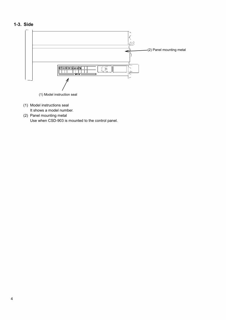
1-3. Side
(1) Model instructions seal
It shows a model number.
(2) Panel mounting metal
Use when CSD-903 is mounted to the control panel.
(2) Panel mounting metal
(1) Model instruction seal

5
2. Connecting wires 2-1. Notes for concerning connecting wires
● When connecting with wires, make sure it was turning off the power supply without fail.
● Do not supply the AC power supply until the installation is completed. There is no switch that switches ON/OFF of power supply in the main body.
● Do not drop the instrument, and do not give a strong impact because the terminal board of the panel is made of resin.
● Be sure to install and use an acrylic cover of the attachment for the terminal board.
● The tightening torque of terminal screws on the terminal board is as shown in the table below.
Terminal board Terminal board screw
tightening torque
Power supply terminal board Loading cell terminal board
0.6 N・m
The solder less terminal that suits the terminal board of this terminal is as shown in the table as below.
Terminal stand Width of solder less
terminal Acceptable Oki
solder less terminal
Power supply terminal board Loading cell terminal board
6.2 mm or less O type 1.25-3 or Y
type 1.25-3.5
● The cable connected with the main body should be separated from the noise source such as I/O for the control, power supply line as possible.
● The Conduit wiring should be the type for exclusive use. Avoid sharing it with other lines.
● Be sure to ground a grounding wire with exclusive use of D-type single grounding. Do not share it with other groundings for power supply.
● The shield cable line is used for the connection of the external control I/O, and the shield with F.G terminal of the power supply terminals

6
2-2. Connection with strain gage applied transducer
The instrument can connect with the strain gage applied transducers, such as load cells, pressure sensors, etc. Here, we describe the example of connection with load cells, so that the connection with another type of strain gage applied transducers shall be preceded in the same way.
When the tension is applied with the use of tension type or universal (tension/compression) type load cell, and display of (+) direction is required, connect the input (+) of the load cell to the terminal B and the input (-) of the load cell to the terminal D individually.
(1) Case 6-wires type connection cable
・ When the length of CAB-501 (our standard cable) is more than 100 m totally, there may have the
case that accuracy is out of warranty as the remote sensing function of the instrument does not work enough due to the resistance of the cable.
・ Shorten the remote sensing input + and remote sensing input – near the main body of load cell. However, when the short is made near the instrument, it will not work as the six-wire type.

7
(2) Case 4-wire type connection cable
・ As using the 4-wire cable, shorten the load cell terminals A - F and C - G with the attached short bar.
CSD-903 does not work in normal operation when the terminal F and G is in the open status.
・ When the length of CAB-502 (our standard cable) is more than 30 m totally, there may have the case that the accuracy is out of warranty due to the resistance of cable, the input voltage of the instrument will be decreased.

8
(3) Case connection of the load cells in parallel
The hopper scale, the track scale, etc, have the case to connect with several pieces of the load cells in parallel. The parallel connections can be easily executed by using optional SB-310 and SB-320 (Summing type junction box).
CSD-903 can make up to 6 parallel connections when the load cell is 350 ohm type. Please consult us as for a method over 5 parallel connections.

9
(4) Connecting with load cell, Junction box B-304B for extension, and CSD-903
1) When you use CAB-502 (4 core cable)
・ When you use it with 4 wires method, be sure to make a short-circuited between A-F and between
C-G of the load cell terminal board. When terminal F and terminal G are used with opening status, CSD-903 cannot make normal operation.
・ There is the possibility of the descent of the input voltage of the instrument at the time of total 30m or more in length of CAB-502 (our standard cable) and also the possibility of outside of accuracy due to the resistance of the cable.
B-304B internal terminal connection

10
2) When you use CAB-501(6 core cable)
The remote sensing function of the instrument does not function enough due to the resistance of the cable at the time of total 100m or more in length of CAB-501 (our standard cable), and there may have the possibility of outside the accuracy guarantee.
B-304B internal terminal connection chart
11
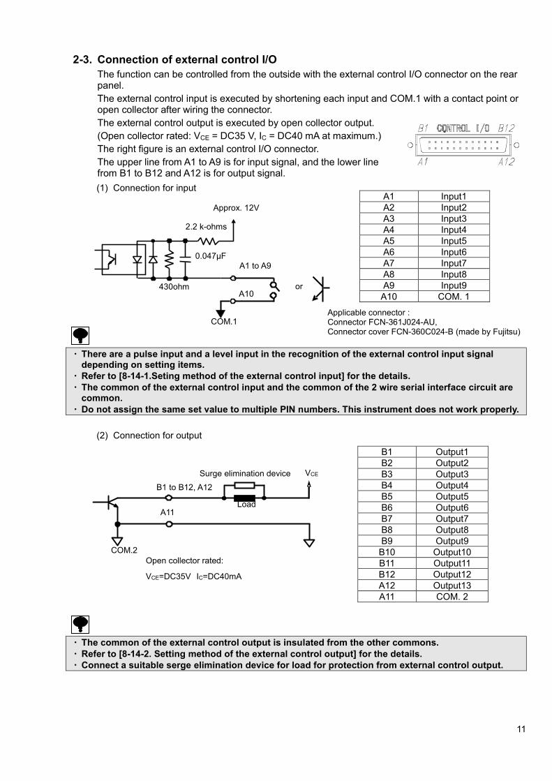
2-3. Connection of external control I/O
The function can be controlled from the outside with the external control I/O connector on the rear panel.
The external control input is executed by shortening each input and COM.1 with a contact point or open collector after wiring the connector.
The external control output is executed by open collector output.
(Open collector rated: VCE = DC35 V, IC = DC40 mA at maximum.)
The right figure is an external control I/O connector.
The upper line from A1 to A9 is for input signal, and the lower line from B1 to B12 and A12 is for output signal.
(1) Connection for input
・ There are a pulse input and a level input in the recognition of the external control input signal
depending on setting items.
・ Refer to [8-14-1.Seting method of the external control input] for the details.
・ The common of the external control input and the common of the 2 wire serial interface circuit are common.
・ Do not assign the same set value to multiple PIN numbers. This instrument does not work properly.
(2) Connection for output
・ The common of the external control output is insulated from the other commons.
・ Refer to [8-14-2. Setting method of the external control output] for the details.
・ Connect a suitable serge elimination device for load for protection from external control output.
A1 Input1
A2 Input2
A3 Input3
A4 Input4
A5 Input5
A6 Input6
A7 Input7
A8 Input8
A9 Input9
A10 COM. 1
B1 Output1
B2 Output2
B3 Output3
B4 Output4
B5 Output5
B6 Output6
B7 Output7
B8 Output8
B9 Output9
B10 Output10
B11 Output11
B12 Output12
A12 Output13
A11 COM. 2
Applicable connector : Connector FCN-361J024-AU, Connector cover FCN-360C024-B (made by Fujitsu)
Approx. 12V
2.2 k-ohms
430ohm
0.047μF A1 to A9
A10
COM.1
or
COM.2
A11
B1 to B12, A12
Load
Surge elimination device VCE
Open collector rated:
VCE=DC35V IC=DC40mA

12
2-4. Connection of standard RS-485 interface
Connect with A, B and S.G. on the output terminals for RS-485 interface and the 2 wire serial interface showing as below figure. Refer to [14-4.Connecting method] as to the connection.
With the standard RS-485, either the command mode or the protocol conforming to the Modbus is selectable.
(Refer to [15.Modbus communication] as to the Modbus communication.)
・ Stripped length of electrical cable tip is 7 mm.
・ The tightening torque of terminal screws on the terminal block is 0.6 N・・・・m.
・ Please use AWG28 ~ AWG16 for connecting cable.
・ The signal ground of standard RS-485 interface and internal common are connected.
・ Please connect the shield with F.G. terminal of RS-485 interface / 2-wires method serial interface terminal by using the shielded cable when CSD-903 complies with the CE conformity or applied JIS standard.
A Differential I/O (+)
B Differential I/O (-)
S.G. Signal ground
Screw side of terminals
Applicable Plug : XW4B-06B-H1.made by OMRON.

13
2-5. Connection with 2-wires Serial interface
This is the 2-wires method serial interface to connect with a printer, an external display unit, etc.
The 2-wires serial interface is connected with +, - and F.G. shown in the below figure.
・ Stripped length of electrical cable tip is 7 mm.
・ The tightening torque of terminal screws on the terminal block is 0.6 N・・・・m.
・ Please use AWG28 ~ AWG16 for connecting cable.
・ There are M252B, etc., made by UNIPULSE as the equipment for the 2-wires method serial interface.
・ The cable must use two cores shielded cable as much as possible and connect the shield with F.G. terminal. Please twist the cable when you don’t use the shielded cable. (The applicable cable length is up to 100 m with shield, and up to 20 m without shield.)
・ The equipment for 2-wires method serial interface can be connected up to three in parallel. (Maximum output current : Approx. DC20 mA)
・ The commons of the external control input and the 2-wires method serial interface are connected.
・ This internal circuit and photo oupler are insulated.
・ Please connect the shield with F.G. terminal of RS-485 interface/2-wires method serial interface terminal by using the shielded cable when CSD-903 complies with the CE conformity or applied JIS standard.
CSD-903Internal equivalent circuit
Serial interface corresponding equipment
Applicable plug : XW4B-06B-H1 (made by OMRON)
Screw side of terminals

14
2-6. Connection with power supply and ground
Connect the power supply with the power supply terminal board on the rear panel of the instrument shown as below figure.
Grounding should be the D class with the single earth.
Warning
Connection with the power supply and the earth should be made surely according to the figures, and also within the specified power supply condition.
・ The grounding of the instrument should be the D-class with single earth.
It may cause an unexpected malfunction due to the effects of noise from other equipments.
・ When suiting the instrument with the CE conformity standard or JIS standard, please make the single earth with a protective ground terminal.
15
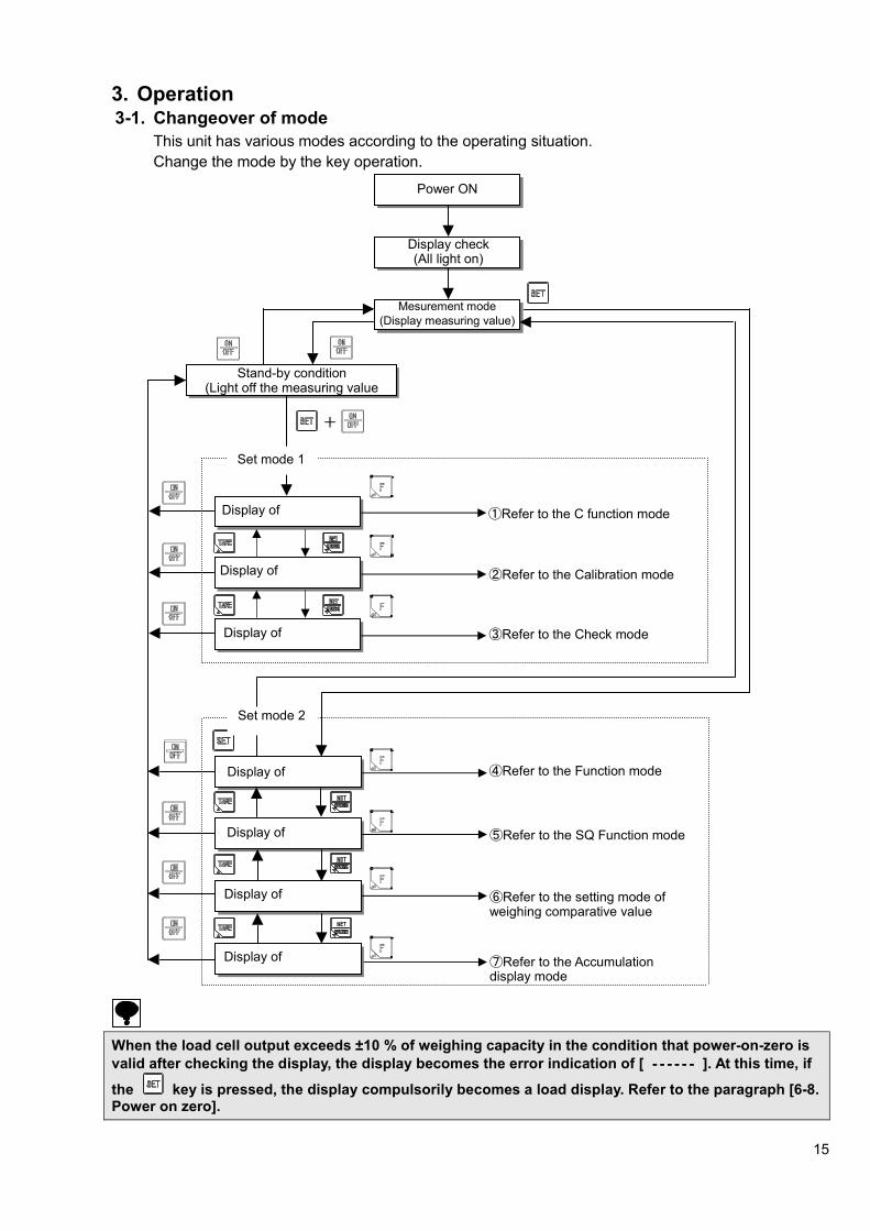
3. Operation 3-1. Changeover of mode
This unit has various modes according to the operating situation.
Change the mode by the key operation.
When the load cell output exceeds ±10 % of weighing capacity in the condition that power-on-zero is
valid after checking the display, the display becomes the error indication of [ ‐‐‐‐‐‐‐‐‐‐‐‐‐‐‐‐‐‐‐‐‐‐‐‐ ]. At this time, if
the key is pressed, the display compulsorily becomes a load display. Refer to the paragraph [6-8. Power on zero].
Set mode 2
④Refer to the Function mode
⑤Refer to the SQ Function mode
⑥Refer to the setting mode of weighing comparative value
Display of
Display of
Display of
Power ON
Display check (All light on)
Display of
Mesurement mode
(Display measuring value)
Stand-by condition (Light off the measuring value
display)
Set mode 1
①Refer to the C function mode
②Refer to the Calibration mode
+
③Refer to the Check mode Display of
Display of
⑦Refer to the Accumulation display mode
Display of

16
(1) C function mode ( )
Various functions which relate to calibration by setting C function data become effective.
(2) Calibration mode ( )
By setting the calibration data, the calibration is executed to display the electric signal from the measuring section (load cell) as an accurate load.
(3) Check mode ( )
The ROM version, the each input/output operation, the monitor of load cell output value, the BCD output and the analog output can be confirmed by the check mode.
(4) Function mode ( )
Various functions become effective because of setting the function data.
(5) SQ function mode ( )
The setting of SQ function data makes various functions related to the sequence operation effective.
(6) Weighing comparative mode ( )
Execute the setting of comparison value of various weighing in the sequence weighing and comparison operation.
(7) Accumulation display mode ( )
The accumulation value and accumulation times can be confirmed for each brand.
Pressing the key clears the accumulation value and accumulation times displayed.

17
4. Calibration To be able to display the electrical signal from the measuring section (load cell) as an accurate weight, the operation to match the display of the instrument with the weight loaded on the measuring section is called a calibration.
For example to adjust the display of this instrument to 100.00 accurately when the weight of 100 kg is loaded on the measuring section is said.
4-1. Set items required in the calibration
(1) Scale interval ( , , , , , )
It is the minimum unit of the measuring value the value to be set is [1], [2], [5], [10], [20] or [50].
The value of {Weighing capacity/Scale interval} is the display resolution.
(2) Weighing capacity ( )
It is the maximum weight to be able to measure by the measuring section (load cell).
(3) Mass of weight used at the span calibration ( )
The span calibration can be executed with the arbitrary weight. The same setting as the weighing capacity is executed when there is a weight for weighing capacity.
Please give setting here as 2/3 or more of weighing capacity to reduce the calibration error.
(4) Calibration at zero ( )
It is a procedure of the calibration to become the zero point of the measurement when nothing is put on the measuring section (status of an initial load). There are [Method by the weighing data (status of an initial load)] and [Method by a numeric input of the load cell output voltage] as a calibration method.
(5) Calibration at span ( )
It is a procedure by which execute the calibration of the change in the electric signal of the load cell when the weight is put on the measuring section to become the display of a correct weighing value.
There are [Method with weight] and [Method by a numeric input of the load cell output voltage] as a calibration method.
4-2. Procedure set if necessary after calibration
(1) Display position of decimal point (C function : )
The decimal point is put on the load display of this unit.
(2) Unit (C function : )
The unit is put on the load display of this unit.
(3) Digital linearize ( )
It is a function the compensation of three points or less except the zero and span, and to reduce the measurement error. Refer to the paragraph 4-5. Digital linearization.
(4) Automatic range switch (C function : ~ )
It is the setting of the second range or the third range for [Multi scale interval scale]. The boundary value and the scale interval within the each range are set. Refer to the [6-13.Automatic range switch].
(5) Gravity acceleration compensation (C function: , )
It is a function for the compensation of the span error by setting the gravity acceleration of the two different districts with a calibration place and a place to be used. Refer to [6-11.Gravity acceleration compensation].
・ Please execute the calibration if necessary when the environment to be used changes.
・ The display resolution that the performance becomes effective is 10 000 or less. The display resolution is a value into which weighing capacity is divided by the scale interval of the first range.
・ The mass of the weight used in the span calibration must use the one of 2/3 or more of weighing capacity to reduce the calibration error.

18
4-3. Calibration procedures
4-3-1. Flow of calibration
Step1 Connect the load cell with this instrument.
Step2 Please energize.
Step3 Please set the bridge power supply.
Step4 To stabilize this unit and the measuring section (load cell); please
make the instrument to the status of energizing for about 10 min.
Step5 Please switch the mode to the calibration mode.
Step6 Please set the scale interval.
Step7 Please set weighing capacity.
Step8 Please set the mass of the weight put on the measuring section.
Step9 Please execute the calibration of the zero point with nothing put on
the measuring section, or by setting the output voltage value of the
zero point of the load cell.
Step10 Please executes the calibration of span by putting the weight on the
measuring section, or by setting the output voltage value of the
span point of the load cell.
Step11 Please quit from the calibration mode. Process the setting since
step 12 showing as follows if necessary.
Paragraph 4-3-2
Switch to the calibration mode
Paragraph 4-3-3
Set the scale interval
Paragraph 4-3-4
Set the weighing capacity
Paragraph 4-3-6
Calibration at zero point
Paragraph 4-3-7
Calibration at span
Connection with load cell
Paragraph 4-3-8
Quit the calibration
Paragraph 4-3-5
Set the mass of the weight
Energy for 10 min after power is turned on.
to Paragraph 6-1
Set the display position of
decimal point
to Paragraph 6-4
Set of the unit to Paragraph 4-5
Digital linearize to Paragraph 6-12
Automatic range switch
to Paragraph 6-11
Gravity acceleration
Step13 Step14 Step15
Energizing power supply
Paragraph 6-5
Set the bridge power supply.
Step12 Step16

19
4-3-2. Switch to the calibration mode
Change from the standard measurement mode to the
stand-by condition by the key.
Pressing the key with the key pressed, it
displays .
Press the key here.
displays.
Press the here.
displays and it enters into the calibration mode.
4-3-3. Set of the scale interval
When key is pressed twice from
display, is displayed. [ ] is the scale interval being memorized now. Please select the scale interval from 1, 2, 5, 10, 20 or 50.
: Selects the scale interval.
: Setting is interrupted and returns to CCAL display.
: The displayed value is memorized, and proceed to the next step.
Press the key after the set.
Calibration mode
Stand-by condition
+
Move to the setting of the scale interval.
The scale interval to be used
Move to set weighing capacity

20
4-3-4. Set weighing capacity
When key is pressed from display,
is displayed. When the weighing capacity has already been changed, the weighing capacity being memorized now is displayed. Here, please set the weighing capacity.
: The value of changed digit is changed.
: Changed digit is selected.
: The value is changed to [0].
: Setting is interrupted and display returns to CCAL.
: The display value is memorized, and it proceed to the next step.
After the setting, press the key.
4-3-5. Setting the mass of the weight
When key is pressed from display
is displayed.
[ ] is the amount of weighing capacity. Please set the mass of the weight actually put on the measuring section here. The same setting as the weighing vcapacity is executed when there is a weight for weighing capacity.
: The value of changed digit is changed.
: Changed digit is selected.
: The value is changed to [0].
: Setting is interrupted and display returns to CCAL.
: The display value is memorized, and it proceed to the next step.
After the setting, press the key.
****
****
Memorized weighing
Changed weighing
Move to setting the mass of the weight.
Move to the calibration of zero point
ひょう量分の分銅値
Weight value put on measurement section.
Mass amount equal to weighing capacity
Memorized weighing capacity
Changed weighing capacity

21
4-3-6. Calibration of zero point
When the zero calibration starts, is displayed.
Please select the zero calibration method.
(1) Method by the measuring data (status of initial load) ⇒ Press the key, and execute the
operation of a).
Execute the calibration of zero with nothing put on the measuring section.
(2) Method by the numeric input of the load cell output voltage. ⇒ Press the key, and execute the
operation of b).
Execute the calibration of zero with inputting the output voltage value of the load cell when nothing is put on the measuring section.
a) Method by the measuring data (status of initial load) Please make that nothing is put on the measuring section.
Press the key when display blinks, and the STABLE mark lights. The
zero point is memorized, and is displayed. b) Method by the numeric input of load cell output voltage.
When key setting is pressed,
is displayed, and when
key is pressed, is displayed also.
[ ] is the memorized output voltage of the load cell. Please set the load cell output voltage in mV/V scale which correspond to the zero point of the measurement.
: The value of changed digit is changed.
: Changed digit is selected.
: The displayed value is changed to [0].
: Setting is interrupted and display returns to CCAL.
: The display value is memorized, and it proceed to the next step.
After the setting, press the key.
Error display in the calibration of zero point
: The display blinks for about two seconds when the output of the load cell is
-2.5 mV/V or less. (Refer to the paragraph 19. Error display)
: The display blinks for about two seconds when the output of the load cell is
2.5 mV/V or more. (Refer to the paragraph 19. Error display)
Move to the calibration of span.
mV/V
mV/V
Memorized load cell output voltage.
Set output voltage of the load cell.
Under the
calibration
of zero.
�Press the
key,
after STABLE
mark lights on.
�Press the
key,
with nothing on
the measuring
section.

22
4-3-7. Calibration of span
When the span calibration starts, is displayed.
Please select the span calibration method.
(1) Method by the measuring ⇒ data Press the key, and execute the operation of a).
Execute the span calibration with weight put on the measuring section.
(2) Method by the numeric output of the load cell output ⇒Press the key, and execute the
operation b).
Execute the span calibration by inputting the value which subtracts the output voltage of the load cell to zero point of measurement set in paragraph 4-3-6. From the output voltage corresponding to the mass of the weight set in paragraph 4-3-5.
a) Method with weight Please put the weight corresponds to mass set in the paragraph 4-3-5 on the measuring section.
Please press the key when
display blinks, and the STABLE mark lights. Span is memorized and
is displayed. b) Method by the numeric input of load cell output voltage.
When key is pressed, is
displayed, and when key is pressed,
is displayed also.
[ ] is the memorized output voltage of the load cell. Please set the value in mV/V scale which subtracts the output voltage of the load cell to zero point of measurement from the output voltage corresponding to the mass of the weighing capacity.
: The value of changed digit is changed.
: Changed digit is selected.
: The displayed value is changed to zero.
: Setting is interrupted and display returns to CCAL.
: The display value is memorized, and it proceeds to the next step.
After the setting, press the key.
Error display in the calibration of span
: The display blinks for about two seconds when ([Load cell output voltage at span]-
[Load cell output voltage at zero point]) ≦ 0.0 mV/V.
(Refer to the paragraph 19. Error display)
: The display blinks for about two seconds when load cell output is 3.1 mV/V or more.
(Refer to the paragraph 19. Error display)
key ispressed withthe weight puton themeasurementsection.
Memorized outputvoltage of the load cell.
mV/V
mV/V
Set output voltage ofthe load cell.
Under thecalibration ofspan.
Press the
keyafter theSTABLE marklights on.

23
4-3-8. Quit the calibration
is displayed when span calibration is completed.
Press the key to quit the calibration mode.
The display becomes , and the set data is memorized internally.
Press the to set to the stand-by condition. The calibration mode is completed.
Please set the fine adjustment of ZERO and SPAN, digital linearize, ZERO set and Tare weight cancellation after the finish of calibration. Those data is cleared if you process the calibration again.
Stand-by condition

24
4-4. Fine adjustment of zero and span
It is the function to make the fine adjustment of zero and span when there is a difference between the actual measuring value and the weight.
4-4-1. Changeover to zero and span fine adjustment mode
Press the key, and move from a usual measurement mode to the stand-by condition.
When key is pressed with key, is displayed.
Press the key here.
is displayed, then key is pressed.
is displayed.
By pressing the key, is displayed, then it enters into the fine adjustment mode of zero and span.
Measurement mode
+
Move to the fine adjustment mode of
zero and span.
Stand-by condition
Fine adjustment mode of zero and span

25
4-4-2. Fine adjustment of zero and span
When key pressed from display,
is displayed. In executing the zero fine adjustment, proceeds the operation of a).
In case of executing the span adjustment only, press key,
and proceed the operation of b) after displaying . a) Fine adjustment of Zero
Press the key. Display becomes . [ ] is the present measuring value, and it can be displayed up to 1/10 digit. Ex. Without a decimal point 0 ~ 6000 -> 0.0 ~ 6000.0 With a decimal point 0.0 ~ 600.0 -> 0.00 ~ 600.00 Please set the display to [zero] after the condition which nothing is put on the measuring point.
: Increase the measuring value. Increase continuously by keeping the key pressed.
: Decrease the measuring value. Decrease continuously by keeping the key pressed.
: Interrupts the setting, and returns to display.
: Memorizes the display value, and proceed to the next step.
After the zero fine adjustment, press the key.
Display becomes . in case of executing the fine adjustment of span, precedes the operation of b).
Otherwise, press the key, and proceed the operation of c)
after displaying . b) Fine adjustment of span Put the weight which can be put on the measuring section under the weighing capacity.
is displayed by pressing the key. [ ] is the present measuring value, and it can be displayed up to 1/10 digit. Please set the display to become the same value with the weight put on the measuring section. After the fine adjustment of span, proceeds the operation of c)
after the display by pressing key.
[A] [B]

26
c) End of fine adjustment mode
Press the key to quit the fine adjustment mode of zero and span.
displayed, and the setting data is memorized to the internal memory.
Press the key, and move to the stand-by condition. The fine adjustment mode of zero and span is completed.
[A] [B]

27
4-5. Digital linearize.
After the calibration, the measurement error of some scale interval levels might be caused between the zero and span (weighing capacity) by the influence of the measuring section etc.
The digital linearization function executes the compensation of three points or less except the zero and span, and to reduce the measurement error.
4-5-1. Changeover to digital linearization mode
Make the condition from the normal measurement mode to the stand-by condition by pressing the
key.
Press the key with pressing the key,
is displayed.
Press the key after pressing the key ,
is displayed.
is displayed after pressing the
key twice, and enter into the digital linearization mode.
Measurement mode
Stand-by condition
Digital linearization mode
Move to the digital linearization mode.
+
Disp
lay
Display
Weight value
Error
Span
0 Zero
Wheight value 0 Zero
Span
Correction point 3
Correction point 2
Correction point 1
After linearization Before linearization

28
4-5-2. Setting of the digital linearization
By pressing the key twice from
display, is displayed. As the display
Becomes → by
pressing the key, please select the numbers of points which wants to compensate linearization, and
press the key
: compensation by 1 point
: compensation by 2 point
: compensation by 3 point Please put the weight of the point which should be the compensation after the display becomes
on the measuring section and press the key.
As the measuring value blinks, press the key
after confirming the stability mark (▼) lighting on.
As the 100 digit of the measuring value blinks, set to the same value with the weights put on the measuring section.
:Increase the measuring value.
:Decrease the measuring value.
:The displayed value is memorized, and proceed to the next step.
:The setting is interrupted, and return to the
display of .
The display becomes when
is selected, and please execute the compensation of the second point.
Additionally, the display becomes
when is selected, and please execute the compensation of the third point.
Please make the value of weight as
< < .
Put the weights.
Confirm the stability mark lighting on.
When P-1 is selected.
When P-2 is selected
[A] [B]
Put the weights.
Confirm the stability mark lighting on.

29
Please press the key when the compensation of each point is completed.
is displayed.
Press the key to complete digital linearization mode.
is displayed, and the setting data is memorized in the internal memory. Please set to the stand-by condition by pressing the
key. The digital linearization mode is finished.
・ Please make the weights to be compensated as <<<< <<<< .
・ The linearization compensation cannot be executed over the weighing capacity.
・ Please refer [19-1. Error load display] as to the details of error display.
・ The compensation data of the digital linearization can be cleared by C function CF-98. Please refer to the paragraph [6-15. Digital linearization clear].
[B] [A]
When P-3 is selected.
Put the weight.
Confirm the stability mark lighting on.

30
4-6. Calibration only of zero point
It is a function for the re-calibration only of the zero point when the amounts of the tare other than the weighing capacity of the measuring section are changed.
4-6-1. Changeover of the calibration mode by zero point
Press the key to change from the measurement mode to the stand-by condition.
is displayed when the key is pressed with the
key.
is displayed by pressing the key after
pressing the key.
is displayed after pressing the key at three times, and entered into the calibration mode only of the zero point.
Measurement mode
+
Stand-by condition
Calibration mode only of zero point

31
Calibration mode only of zero point
Please make the display to by pressing
the key from the display of . Please make to the status where nothing is put on the measuring section here excluding the tare outside weighing capacity.
The display of blinks by pressing the key, and start the calibration at zero.
Press the key after the stability mark lighting on.
The calibration of zero point is completed, and is displayed.
Press the key to finish the calibration mode only of zero point.
is displayed, and the setting data is memorized in the internal memory.
Please set to the stand-by condition by pressing the key. The calibration mode only of zero point is finished.
Error display in the calibration of zero point
: The display blinks for about 2 seconds when the load cell output is less than -2.5 mV/V.
(Please refer to the paragraph 19. Error display.)
: The display blinks for about 2 seconds when the load cell output is over 2.5 mV/V.
(Please refer to the paragraph 19. Error display.)

32
4-7. LOCK of calibration
The function change in the calibration and C function can be prohibited by the switch of rear panel.
4-7-1. LOCK by the switch
There is calibration LOCK switch inside when the cover at the right of terminals of RS-485 interface and 2-wires type serial interface in the rear panel.
・ When the calibration LOCK is at the effective, the mode of [ ] or [ ] cannot be used.
・ When the calibration LOCK is at the effective, the rewriting C function data by communication and the communication calibration is cannot.
Calibration Lock switch
Calibration Lock switch cover
Installation screw
For calibration Lock switch cover
LOCK ON LOCK OFF

33
5. C function mode The various functions concerning to the calibration become effective by setting the C function data.
5-1. Setting method of C function data
Press the key to change the condition from normal measurement mode to stand-by condition.
When the key is pressed with pressing the key,
is displayed.
By pressing the key, is displayed. Please select C function number which wants to change.
: The value of the changed digit is changed.
: Select the changed digit.
: Change the display value to [0].
: Return to the display of .
: Memorize the display value, and proceed to the next step.
: Finish the C function mode without changing all setting.
By pressing the key, please change the setting value of selected C function mode.
By pressing the key. The changed content is registered, and the following changed C function number is displayed on the panel. Please select the changed C function number when you continuously change the setting of the other C function numbers.
By pressing key is pressed after the registration is
completed, is displayed.
By pressing the key, set to the stand-by condition.
Measurement mode
Stand-by condition
+
Registration is
completed.
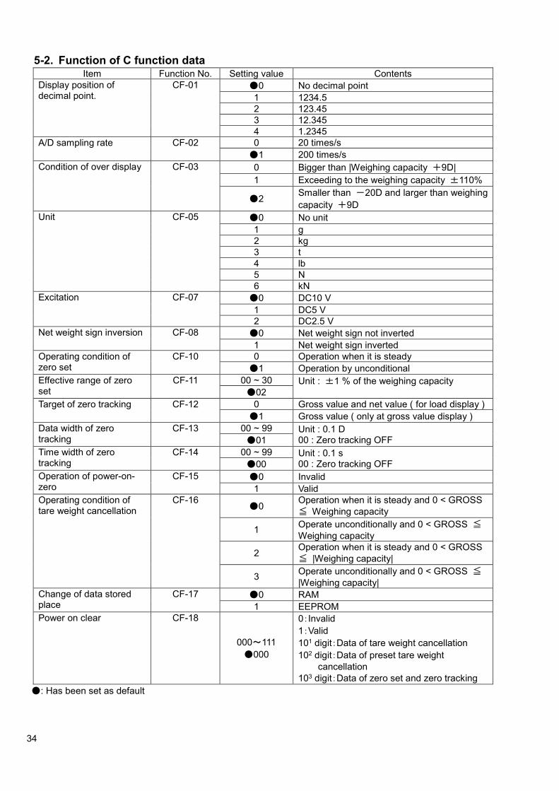
34
5-2. Function of C function data Item Function No. Setting value Contents
Display position of decimal point.
CF-01 ●0 No decimal point
1 1234.5
2 123.45
3 12.345
4 1.2345
A/D sampling rate CF-02 0 20 times/s
●1 200 times/s
Condition of over display CF-03 0 Bigger than |Weighing capacity +9D|
1 Exceeding to the weighing capacity ±110%
●2 Smaller than -20D and larger than weighing
capacity +9D
Unit CF-05 ●0 No unit
1 g
2 kg
3 t
4 lb
5 N
6 kN
Excitation CF-07 ●0 DC10 V
1 DC5 V
2 DC2.5 V
Net weight sign inversion CF-08 ●0 Net weight sign not inverted
1 Net weight sign inverted
Operating condition of zero set
CF-10 0 Operation when it is steady
●1 Operation by unconditional
Effective range of zero set
CF-11 00 ~ 30 Unit : ±1 % of the weighing capacity
●02
Target of zero tracking CF-12 0 Gross value and net value ( for load display )
●1 Gross value ( only at gross value display )
Data width of zero tracking
CF-13 00 ~ 99 Unit : 0.1 D 00 : Zero tracking OFF ●01
Time width of zero tracking
CF-14 00 ~ 99 Unit : 0.1 s 00 : Zero tracking OFF ●00
Operation of power-on- zero
CF-15 ●0 Invalid
1 Valid
Operating condition of tare weight cancellation
CF-16 ●0
Operation when it is steady and 0 < GROSS
≦ Weighing capacity
1 Operate unconditionally and 0 < GROSS ≦
Weighing capacity
2 Operation when it is steady and 0 < GROSS
≦ |Weighing capacity|
3 Operate unconditionally and 0 < GROSS ≦
|Weighing capacity|
Change of data stored place
CF-17 ●0 RAM
1 EEPROM
Power on clear CF-18
000~111
●000
0:Invalid
1:Valid
101 digit:Data of tare weight cancellation
102 digit:Data of preset tare weight
cancellation
103 digit:Data of zero set and zero tracking
●: Has been set as default

35
Item Function No. Setting value Contents
Stability detection while the set mode 2 or set of preset tare
CF-20 ●0 Invalid
1 Effective
Unit display in sub- display section while the set mode 2 or set of preset tare
CF-21 ●0 Invalid
1 Effective
Method of setting gravity acceleration compensation
CF-25 ●0 Set the district number
1 Set the numerical value of gravity acceleration
District number of using place CF-26 (Possible to set
at CF25 = 0)
01 ~ 16 Unit : District
●10
District number of calibration place CF-27 (Possible to set
at CF25 = 0)
01 ~ 16 Unit : District
●10
Gravity acceleration value setting of using place
CF-28 (Possible to set
at CF25 = 1)
9.000 ~ 9.999
●9.797
Unit : m/s2
Gravity acceleration value setting of calibration place
CF-29 (Possible to set
at CF25 = 1)
9.000 ~ 9.999
●9.797
Unit : m/s2
Range switch operation CF-40 ●0 Range change OFF
1 Changeable two ranges
2 Changeable three ranges
Set of scale interval of the second range
CF-41 0 1 scale interval
1 2 scale interval
2 5 scale interval
●3 10 scale interval
4 20 scale interval
5 50 scale interval
Boundary value setting in the second range
CF-42 000000 ~ 999999
●003000
Set of scale interval of the third range
CF-43 0 1 scale interval
1 2 scale interval
2 5 scale interval
●3 10 scale interval
4 20 scale interval
5 50 scale interval
Boundary value setting in the third range
CF-44 000000 ~ 999999
●006000
Analog output target CF-70 ●0 Display interlock
1 Gross value
2 Net value
Display value at the analog output of DC4 mA(DC0 V)
CF-71 -999999 ~ 999999
●000000
Unit : 1D
Display value at the analog output of DC20 mA(DC10 V)
CF-72 -999999 ~ 999999
●010000
Unit : 1D
Calibration data of the maximum capacity (Reference use)
CF-90 ●1
Calibration data of weighing capacity (Reference use)
CF-91 ●10000
●Has been set as default

36
Item Function No. Setting value Contents
Calibration data of the weight (Reference use)
CF-92 ●10000
Calibration data of zero mV/V (Reference use)
CF-93 ●0.00000
Calibration data of span mV/V (Reference use)
CF-94 ●0.30000
Stability detection time width at calibration
CF-97 00 ~ 99
●05 Unit : 0.1 s 00 : OFF of stability detection at calibration
Digital linearization clear CF-98 The data of the compensation by the digital linearization is cleared.
Memory clear CF-99 C function set content is returned default setting.
●Has been set as default

37
6. Various functions by C function data 6-1. Setting of decimal point display position
The decimal point display position is selected by C function CF-01.
The position of the decimal point can be selected from [Nothing], [1234.5], [123.45], [12.345] or [1.2345].
Default is set to [Nothing].
6-2. A/D sampling rate
The A/D sampling rate is selected by C function CF-02
The A/D sampling rate can be selected from [200 times/s] or [20 times/s].
Default is set to [200 times/s].
The A/D sampling rate decreases temporarily while writing the changed data of set value in EEPROM.
6-3. Condition of over display ( or display)
The over display condition is selected by C function CF-03.
[At the time of more than |weighing capacity + 9D|], [at the time of exceeding to the weighing
capacity ±110 %] or [Exceeding to -20D to weighing capacity] can be selected.
Default is set to [Smaller than -20D and larger than weighing capacity +9D].
6-4. Unit
The unit is selected by C function CF-05.
The unit can be selected from [No unit], [g], [kg], [t], [lb], [N] or [kN].
Default is set to [No unit].
6-5. Excitation
Excitation is selected by C function CF-07.
The voltage (DC) excited to the load cell can be selected from [DC10 V], [DC5 V] and [DC2.5 V].
Default is set to [DC10 V].
When CSD-903 is applied for the system where zener barrier is used, apply it by selecting the excitation properly according to the below table.
System configuration Excitation
10 V 5 V 2.5 V
1 point of load cell + zener barrier × ○ ○
2 points of load cell + Summing type junction box + zener barrier × × ○
3 points of load cell + Summing type junction box + zener barrier × × ○
4 points of load cell + Summing type junction box + zener barrier × × ○
5 points of load cell + Summing type junction box + zener barrier × × ○
6 points of load cell + Summing type junction box + zener barrier × × ×
○ : Applicable. × : Not Applicable.
The above are the examples when CAB-501 (6-cores) type of cable and 350 Ω type of load cell are
applied.

38
6-6. Net weight sign inversion
The net weight sign inversion function is used to invert the sign of the net weight display and net weight data output externally, for example, in simple comparison discharging mode.
The net weight sign inversion function is a function for making the net weight display or net weight data output externally positive by inverting the sign of the net weight using C function CF-08.
Net weight sign inversion can be selected from [Net weight sign not inverted] or [Net weight sign inverted].
Default is set to [Net weight sign not inverted].
6-7. Zero set
The zero set function memorizes a present measuring value as zero point and adjusts the display to
zero by pressing the key when the indicated value of the load display section is the gross value and at the same time Zero set effective range.
6-7-1. Operating condition of zero set
The operating condition of zero set is selected by C function CF-10.
The effective range is common for both of zero set and zero tracking.
[Operation at steady] or [Unconditional operation] can be selected.
Default is set to [Operation at steady].
6-7-2. Zero set effective range
The effective range of zero set is selected by C function CF-11
Setting range: 00 – 30 Unit : ±1 % of the weighing capacity, 00: OFF
Default is set to [02].
・ When the zero compensation for the effective range is executed by the zero set and the zero
tracking, the zero set is not accepted.
・ When the tare weight cancellation or the preset tare weight cancellation is executed, zero set shall be executed after clearing the tare weight cancellation and the preset tare weight cancellation.
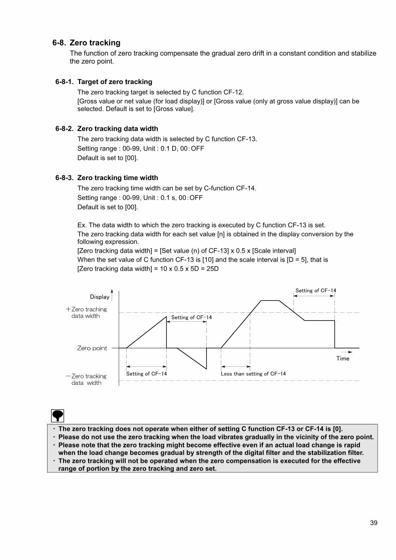
39
6-8. Zero tracking
The function of zero tracking compensate the gradual zero drift in a constant condition and stabilize the zero point.
6-8-1. Target of zero tracking
The zero tracking target is selected by C function CF-12.
[Gross value or net value (for load display)] or [Gross value (only at gross value display)] can be selected. Default is set to [Gross value].
6-8-2. Zero tracking data width
The zero tracking data width is selected by C function CF-13.
Setting range : 00-99, Unit : 0.1 D, 00:OFF
Default is set to [00].
6-8-3. Zero tracking time width
The zero tracking time width can be set by C-function CF-14.
Setting range : 00-99, Unit : 0.1 s, 00:OFF
Default is set to [00].
Ex. The data width to which the zero tracking is executed by C function CF-13 is set.
The zero tracking data width for each set value [n] is obtained in the display conversion by the following expression.
[Zero tracking data width] = [Set value (n) of CF-13] x 0.5 x [Scale interval]
When the set value of C function CF-13 is [10] and the scale interval is [D = 5], that is
[Zero tracking data width] = 10 x 0.5 x 5D = 25D
・ The zero tracking does not operate when either of setting C function CF-13 or CF-14 is [0].
・ Please do not use the zero tracking when the load vibrates gradually in the vicinity of the zero point.
・ Please note that the zero tracking might become effective even if an actual load change is rapid when the load change becomes gradual by strength of the digital filter and the stabilization filter.
・ The zero tracking will not be operated when the zero compensation is executed for the effective range of portion by the zero tracking and zero set.
Zero trackingdata width
Less than setting of CF-14
Setting of CF-14
Setting of CF-14
Setting of CF-14
Zero trachingdata width
Zero point
+
-
Dis
pla
yDisplay
Time

40
6-9. Power on zero
The power on zero function changes the display to zero if the changes of display is within ±10 % of
the maximum capacity when the power is turn on, or in the stable condition in the operation of display turning on.
6-9-1. The operation of power on zero
The operation of power on zero is selected by C function CF-15.
The power-on-zero operation is selected from [Effective] and [Invalid].
Default is set to [Invalid].
・ The zero compensation is not accepted in the following condition when the setting of C functions
CF-15 is [Effective power on zero] and when power on zero is starting. (1) When the display is not a stable condition, it becomes as all lighting.
(2) When the measurement value exceeds ±±±±10 % of the weighing capacity, [ ‐‐‐‐‐‐‐‐‐‐‐‐‐‐‐‐‐‐‐‐‐‐‐‐ ] is displayed.
At this time, by pressing the key, the display becomes a load value compulsorily.
・ When the power on zero is executed, each data of tare weight cancellation, preset tare weight cancellation, zero set and zero tracking shall be all cleared.
6-10. Tare weight cancellation
By pressing the key, the indication of [TARE] and [NET] in the condition display section is turned on and the display changes to zero.
To execute the tare weight cancellation clear, press the key when the gross value is zero. The tare weight cancellation is cleared and [GROSS] of the condition display section lights at the same time as becoming a gross value display.
6-10-1. Operating condition of tare weight cancellation
The operating condition of tare weight cancellation is selected by C function CF-16.
[Operation when it is steady and 0 < GROSS ≦ WEIGHING CAPACITY],
[Operate unconditionally and 0 < GROSS ≦ WEIGHING CAPACITY],
[Operation when it is steady and 0 < GROSS ≦ | WEIGHING CAPACITY |] and
[Operate unconditionally and 0 < GROSS ≦ | WEIGHING CAPACITY |] can be selected.
Default is set to [Operation when it is steady and 0 < GROSS ≦ WEIGHING CAPACITY]
・ The tare weight cancellation is not accepted when the gross value is larger than the first range.
・ When the tare weight cancellation is executed with a preset tare weight cancellation executed, a preset tare weight cancellation is canceled, and the tare weight cancellation is executed. (A preset tare weight cancellation cannot be used together with the tare weight cancellation)
・ When the zero set is executed in the condition of gross value display, the tare weight cancellation will be cancelled.
41
6-11. Clear at power on
Setting of the clear at power on is selected by C function CF-18.
Clear at power on function is clear [Data of tare weight cancellation],
[Data of preset tare weight cancellation] and [Data of zero set and zero tracking] when the power is turn on, or in the operation of display turning on.
Setting: 000 ~ 111, 0: Invalid, 1: effective, Default: 000
100: Data of tare weight cancellation
101: Data of preset tare weight cancellation
102: Data of zero set and zero tracking
6-12. Setting while set mode 2 or set of preset tare
Proceed to set the unit display in sub-display section and the stability detections in condition display while the set mode 2 or set of preset tare.
6-12-1. Operation for stability detection
The selection whether the stability detection is effective or invalid is made by C function CF-20.
Default is set to [Invalid].
6-12-2. Operation for unit display in sub-display section
The selection whether the unit display in sub-display section is effective or invalid is made by C function CF-21. Default is set to [Invalid].
6-13. Gravity acceleration compensation
When the calibration place and the using place of the measuring are different, the error is caused in span by the difference of the gravity acceleration of the various place districts.
The gravity acceleration compensation function is a function for the compensation of this span error by setting the gravity acceleration of two districts with a different calibration place and using place.
When the calibration place and the using place are the same, it is not necessary to execute the gravity acceleration compensation.
6-13-1. Setting method of gravity acceleration compensation
The setting method of the gravity acceleration compensation is selected by C function CF-25.
[The district number is set] or [The numerical value of gravity acceleration is set] can be selected.
Default is set to [The district number is set].
6-13-2. Setting of district number of the using place (When CF-25: 0)
The setting of the district number of the using place is executed by C function CF-26.
The setting of district number: 01 ~ 16
Default is set to 10 districts.
Please refer to [Gravity acceleration compensation table] in the next page.
6-13-3. Setting of district number of the calibration place (When CF-25: 0)
The district number of the calibration place can be set by C function CF-27.
The set of the district number: 01 ~ 16
Default is set to 10 districts.
Please refer to [Gravity acceleration compensation table] in the next page.
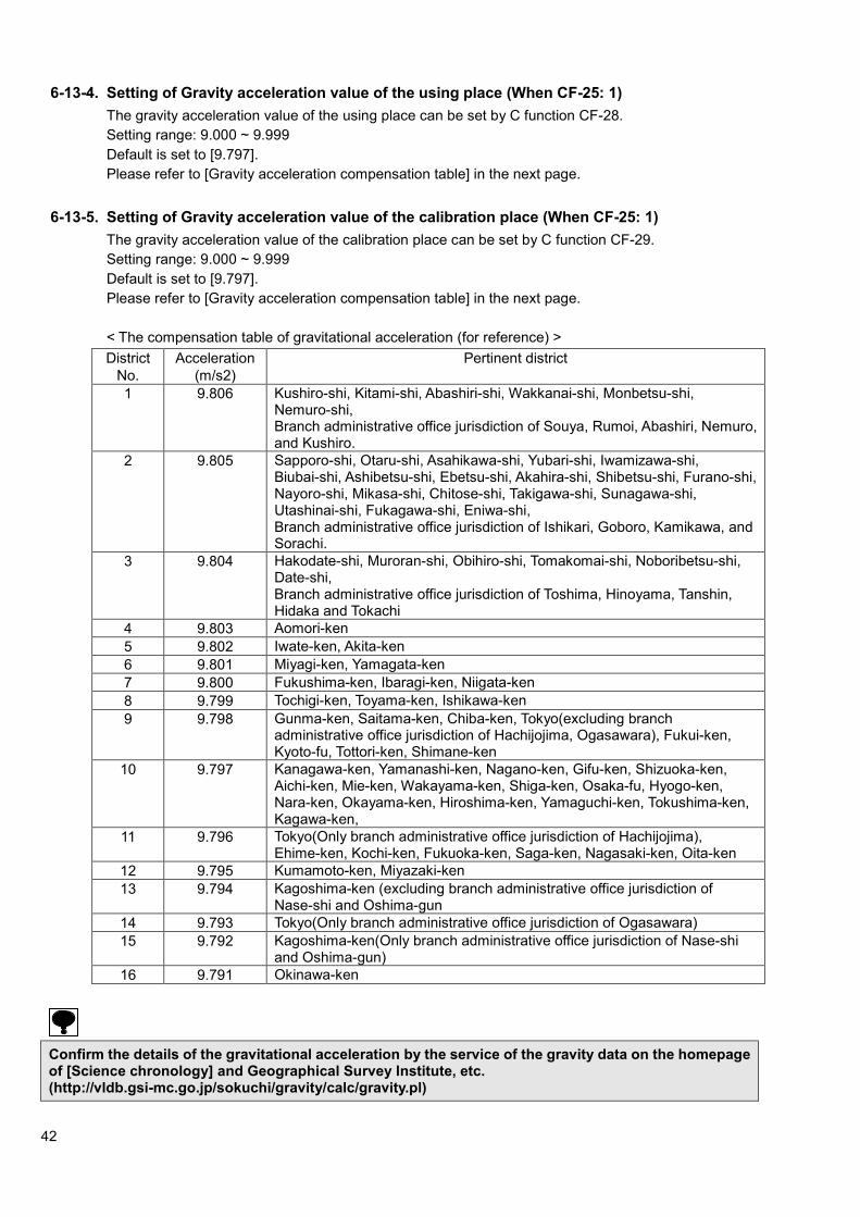
42
6-13-4. Setting of Gravity acceleration value of the using place (When CF-25: 1)
The gravity acceleration value of the using place can be set by C function CF-28.
Setting range: 9.000 ~ 9.999
Default is set to [9.797].
Please refer to [Gravity acceleration compensation table] in the next page.
6-13-5. Setting of Gravity acceleration value of the calibration place (When CF-25: 1)
The gravity acceleration value of the calibration place can be set by C function CF-29.
Setting range: 9.000 ~ 9.999
Default is set to [9.797].
Please refer to [Gravity acceleration compensation table] in the next page.
< The compensation table of gravitational acceleration (for reference) >
District
No.
Acceleration
(m/s2)
Pertinent district
1 9.806 Kushiro-shi, Kitami-shi, Abashiri-shi, Wakkanai-shi, Monbetsu-shi, Nemuro-shi, Branch administrative office jurisdiction of Souya, Rumoi, Abashiri, Nemuro, and Kushiro.
2 9.805 Sapporo-shi, Otaru-shi, Asahikawa-shi, Yubari-shi, Iwamizawa-shi, Biubai-shi, Ashibetsu-shi, Ebetsu-shi, Akahira-shi, Shibetsu-shi, Furano-shi, Nayoro-shi, Mikasa-shi, Chitose-shi, Takigawa-shi, Sunagawa-shi, Utashinai-shi, Fukagawa-shi, Eniwa-shi, Branch administrative office jurisdiction of Ishikari, Goboro, Kamikawa, and Sorachi.
3 9.804 Hakodate-shi, Muroran-shi, Obihiro-shi, Tomakomai-shi, Noboribetsu-shi, Date-shi, Branch administrative office jurisdiction of Toshima, Hinoyama, Tanshin, Hidaka and Tokachi
4 9.803 Aomori-ken
5 9.802 Iwate-ken, Akita-ken
6 9.801 Miyagi-ken, Yamagata-ken
7 9.800 Fukushima-ken, Ibaragi-ken, Niigata-ken
8 9.799 Tochigi-ken, Toyama-ken, Ishikawa-ken
9 9.798 Gunma-ken, Saitama-ken, Chiba-ken, Tokyo(excluding branch administrative office jurisdiction of Hachijojima, Ogasawara), Fukui-ken, Kyoto-fu, Tottori-ken, Shimane-ken
10 9.797 Kanagawa-ken, Yamanashi-ken, Nagano-ken, Gifu-ken, Shizuoka-ken, Aichi-ken, Mie-ken, Wakayama-ken, Shiga-ken, Osaka-fu, Hyogo-ken, Nara-ken, Okayama-ken, Hiroshima-ken, Yamaguchi-ken, Tokushima-ken, Kagawa-ken,
11 9.796 Tokyo(Only branch administrative office jurisdiction of Hachijojima), Ehime-ken, Kochi-ken, Fukuoka-ken, Saga-ken, Nagasaki-ken, Oita-ken
12 9.795 Kumamoto-ken, Miyazaki-ken
13 9.794 Kagoshima-ken (excluding branch administrative office jurisdiction of Nase-shi and Oshima-gun
14 9.793 Tokyo(Only branch administrative office jurisdiction of Ogasawara)
15 9.792 Kagoshima-ken(Only branch administrative office jurisdiction of Nase-shi and Oshima-gun)
16 9.791 Okinawa-ken
Confirm the details of the gravitational acceleration by the service of the gravity data on the homepage of [Science chronology] and Geographical Survey Institute, etc. (http://vldb.gsi-mc.go.jp/sokuchi/gravity/calc/gravity.pl)

43
6-14. Automatic range switch
Automatic range switch function switches automatically and displays the scale interval by the measuring data of the gross or net value by dividing the range of the measurement to the weighing capacity into 2 or 3.
6-14-1. Setting of the range switch operation
The range switch operation can be selected by C function CF-40.
The range switch can be selected from [OFF (without range switch)], [Two range switch] and [Three range switch].
Default is set to [OFF].
6-14-2. Setting the scale interval of the second range
The scale interval of the second range can be set by the C function CF-41.
The scale interval can be selected from [1 scale interval], [2 scale interval], [5 scale interval], [10 scale interval], [20 scale interval] and [50 scale interval]. Default is set to [5 scale interval].
6-14-3. Setting the boundary value of the second range
The boundary value of the second range can be set by C function CF-42.
Setting range: 0 ~ 999999, Default is set to [003000].
6-14-4. Setting the scale interval of the third range
The scale interval of the third range can be set by the C function CF-43.
The scale interval can be selected from [1 scale interval], [2 scale interval], [5 scale interval], [10 scale interval], [20 scale interval] and [50 scale interval]. Default is set to [10 scale interval].
6-14-5. Setting the boundary value of the third range
The boundary value of the third range can be set by C function CF-44.
Setting range: 0 ~ 999999. Default is set to [006000].
Ex.1 In case of gross value
The first range: 300.0 g (Boundary of the second range), scale interval 0.1 g (The scale interval in calibration)
The second range: 600.0 g (Boundary of the third range), scale interval 0.5 g (Scale interval of the second range)
The third range: 1 000.0 g (The weighing capacity), scale interval 1 g (Scale interval of the third range)
The measurement from 0 to 300 g becomes the first range (scale interval 0.1 g).
The measurement from 300 to 600 g becomes the second range (scale interval 0.5 g).
The measurement from 600 to 1 000 g becomes the second range (scale interval 1 g).
0 g 300 g 600 g 1 000 g
目量 0.1 g
目量 0.5 g
目量 1 g
計量値
Scale interval 0.1 g
Scale interval 0.5 g
Scale interval 1 g
Measurement value
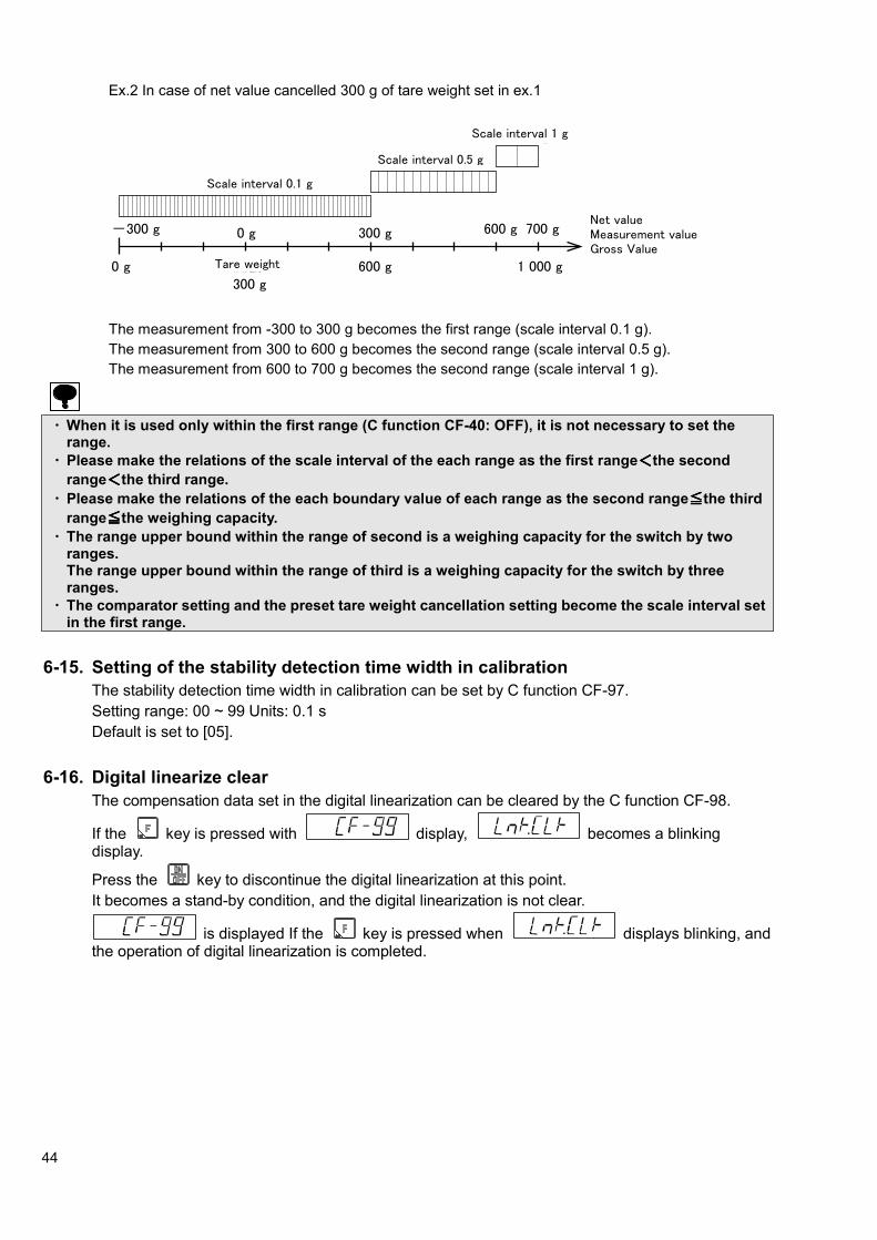
44
Ex.2 In case of net value cancelled 300 g of tare weight set in ex.1
The measurement from -300 to 300 g becomes the first range (scale interval 0.1 g).
The measurement from 300 to 600 g becomes the second range (scale interval 0.5 g).
The measurement from 600 to 700 g becomes the second range (scale interval 1 g).
・ When it is used only within the first range (C function CF-40: OFF), it is not necessary to set the
range.
・ Please make the relations of the scale interval of the each range as the first range<<<<the second
range<<<<the third range.
・ Please make the relations of the each boundary value of each range as the second range≦≦≦≦the third
range≦≦≦≦the weighing capacity.
・ The range upper bound within the range of second is a weighing capacity for the switch by two ranges. The range upper bound within the range of third is a weighing capacity for the switch by three ranges.
・ The comparator setting and the preset tare weight cancellation setting become the scale interval set in the first range.
6-15. Setting of the stability detection time width in calibration
The stability detection time width in calibration can be set by C function CF-97.
Setting range: 00 ~ 99 Units: 0.1 s
Default is set to [05].
6-16. Digital linearize clear
The compensation data set in the digital linearization can be cleared by the C function CF-98.
If the key is pressed with display, becomes a blinking display.
Press the key to discontinue the digital linearization at this point.
It becomes a stand-by condition, and the digital linearization is not clear.
is displayed If the key is pressed when displays blinking, and the operation of digital linearization is completed.
0 g 風袋300 g
600 g 1 000 g
目量 0.1 g
目量 0.5 g
目量 1 g
計量値0 g-300 g 300 g 600 g 700 g
総量
正味量
Scale interval 0.1 g
Scale interval 0.5 g
Scale interval 1 g
Net value Measurement value Gross Value
Tare weight

45
6-17. Memory clear
A clear memory is executed by C function CF-99, and the setting contents of C function is returned to the default setting.
By pressing the key in the display condition of , becomes a blinking.
Please press the key to discontinue the clear memory at this point.
It becomes a stand-by mode, and digital linearization is not clear.
If the key is pressed when displays blinking, the display section is turned off
and becomes to display, then the operation of memory clear is completed.
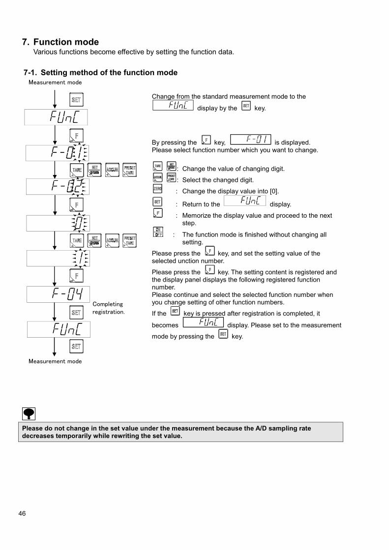
46
7. Function mode Various functions become effective by setting the function data.
7-1. Setting method of the function mode
Change from the standard measurement mode to the
display by the key.
By pressing the key, is displayed. Please select function number which you want to change.
: Change the value of changing digit.
: Select the changed digit.
: Change the display value into [0].
: Return to the display.
: Memorize the display value and proceed to the next step.
: The function mode is finished without changing all setting.
Please press the key, and set the setting value of the selected unction number.
Please press the key. The setting content is registered and the display panel displays the following registered function number. Please continue and select the selected function number when you change setting of other function numbers.
If the key is pressed after registration is completed, it
becomes display. Please set to the measurement
mode by pressing the key.
Please do not change in the set value under the measurement because the A/D sampling rate decreases temporarily while rewriting the set value.
Measurement mode
Completing registration.
Measurement mode

47
7-2. Function of the function data Item Function No. Setting value Contents
Setting of digital filter F-01 001 ~ 256
●016
Unit : Moving average time 1 times
Setting of analog filter F-02 0 2 Hz
●1 4 Hz
2 6 Hz
3 8 Hz
4 10 Hz
Display times F-04 ●0 4 times/s
1 20 times/s
Setting of stabilizating filter F-05 001 ~ 256
●092
Unit : Moving average time 1 times
Data width of stabilizing filter F-06 000 ~ 999
●020
Unit : 0.1D 000 : Stabilization filter OFF
Time width of stabilizing filter F-07 00 ~ 99
●05
Unit : 0.1 s 00 : Stabilization filter OFF
Lock the key 1 F-08 0000 ~ 1111
●0000
0 : Invalid 1 : Valid 100 : key for ON/OFF 101 : key for setting
102 : key for accumulation/ 103 : key for the set of tare weight/
Lock the key 2 F-09 0000 ~ 1111
●0000
0 : Invalid 1 : Valid
100 : key for tare weight cancellation/▲
101 : key for net or gross weight/▼
102 : key for zero set 103 : key for F/
Stability detection data width F-10 000 ~ 999
●020
Unit : 0.1D 00 : Stabilization filter OFF
Stability detection time width F-11 00 ~ 99
●10
Unit : 0.1 s 00 : Stabilization filter OFF
Operating condition of the preset tare weight cancellation
F-15 ●0 Invalid
1 Effective
2 Net weight offset operation
Automatic print operation F-16 00 ~ 11
●00
100 digits : manual print operation effective only in the stable. 0 : effective only in the stable 1 : always effective 101 digit : Automatic print operation 0 : turn off the automatic printing 1 : automatic printing in the stable
Hold operation F-17 ●0 Synchronizing with Hold
1 Synchronizing with Batch Finish
Target of Hold F-18 0000 ~ 1111
●0001
0 : Invalid 1 : Valid 100 digit : Display 101 digit : Comparison result 102 digit : CC-link interface 103 digit : Serial interface
● Has been set as default

48
Item Function No. Setting value Contents
Selection of sub display section
F-19 ●0 OFF
1 A Brand (1 digit) / Accumulation times (6 digits) / Accumulation value (8 digits)
2 B Brand (1 digit) / Accumulation times (6 digits) / Last accumulated data (6 digits)
3 C Brand (1 digit) / Last accumulated data (6 digits) / Accumulation value (8 digits)
4 D Brand (1 digit) / Last accumulated data (6 digits) / OK (6 digits)
5 E Brand (1 digit) / Accumulation times (6 digits) / OK (6 digits)
6 F Brand (1 digit) / OK (6 digits) / Accumulation value (8 digits)
7 G Brand (1 digit) / Near zero (6 digits) / Full (6 digits)
8 (No letter) OK (6 digits) / Over (5 digits) / Under (5 digits)
9 I Brand (1 digit) / OK (6 digits) / Free fall (6 digits)
10 J Brand (1 digit) / S1 (6 digits) / S2 (6 digits)
11 K Brand (1 digit) / S1 (6 digits) / S3 (6 digits)
12 L Brand (1 digit) / S1 (6 digits) / S4 (6 digits)
13 M Brand (1 digit) / S2 (6 digits) / S3 (6 digits)
14 N Brand (1 digit) / S2 (6 digits) / S4 (6 digits)
15 O Brand (1 digit) / S3 (6 digits) / S4 (6 digits)
16 P Brand (1 digit) / OK (6 digits)
17 Q Brand (1 digit) / Over (5 digits) / Under (5 digits)
18 R Brand (1 digit) / Accumulation times (6 digits)
19 S Brand (1 digit) / Accumulation value (10 digits)
20 T Brand (1 digit) / Last accumulated data (6 digits)
Brand setting target on comparator
F-20 ●0 Brand 0
1 Brand 1
2 Brand 2
3 Brand 3
4 Brand 4
5 Brand 5
6 Brand 6
7 Brand 7
Operation target on 4 steps comparator
F-21 0000 ~ 1111
●0000
0 : Display interlock
1 : Gross
2 : Net
100 digit:Comparator S1
101 digit:Comparator S2
102 digit:Comparator S3
103 digit:Comparator S4
●Has been set as default

49
Item Function No. Setting value Contents
Operation on 4 steps comparator
F-22 0000 ~ 1111
●0000
0 : OFF
1 : More than
2 : Less than
100 digit:Comparator S1
101 digit:Comparator S2
102 digit:Comparator S3
103 digit:Comparator S4
Operation of 4 steps comparator S0
F-23 ●0 Always OFF
1 On when both of S1 and S2 output are OFF
2 On when both of S1 and S3 output are OFF
3 On when both of S1 and S4 output are OFF
4 On when both of S2 and S3 output are OFF
5 On when both of S2 and S4 output are OFF
6 On when both of S3 and S4 output are OFF
7 On when (Gross weight)≧(Weighing capacity)
Comparator hysteresis operating conditions
F-24 ●0 On delay
1 Off delay
Width of comparator hysteresis data
F-25 00 ~ 99
●00 Unit : 1D 00 : Hysteresis OFF
Width of comparator hysteresis time
F-26 00 ~ 99
●00 Unit : 0.1 s 00 : Hysteresis OFF
BCD output operation mode
F-30 ●0 Stream
1 Synchronizing with print
2 Synchronizing with accumulation
3 Synchronizing with finish
BCD output target F-31 ●0 Display interlock
1 Gross value
2 Net value
3 Tare weight value
4 Accumulation total amount
5 Accumulation frequency
BCD output logic F-32 0000 ~ 1111
●0000
0 : Negative logic 1 : Positive logic 100 digit : Data output logic (Load data and decimal point) 101 digit : Polarity logic 102 digit : Flag logic (ERROR, OVER, Stable, Gross) 103 digit : P.C. (Print command) logic
BCD P.C. (Print command) width
F-33 0 125 ms
●1 25 ms
2 5 ms
BCD output times F-34 ●0 4 times/s
1 20 times/s
2 100 times/s
S-I/F automatic print operation
F-37 ●0 OFF
1 Synchronizing with print signal
2 Synchronizing with accumulation signal
3 Synchronizing with finish signal
● Has been set as default.

50
Item Function No. Setting value Contents
RS-232C operating mode F-40 ●0 Command mode
1 Stream mode
2 Synchronizing with finish signal
3 Synchronizing with accumulation signal
4 Synchronizing with print signal
Output target of RS-232C/422/485
F-41 (RS-232C : Valid at F-40 = 1 or 4,
RS-422/485 : Valid at F-49=1)
●0 Display interlock
1 Gross value
2 Net value
3 Load display data with condition
RS-232C/422/485 specification for communication
F-42 ●13020 Data bit length
100 digit : ●0 = 7 bit, 1 = 8 bit
Parity 101 digit : 0 = No parity, 1 = Even parity
●2 = Odd parity
Stop bit
102 digit : ●0 = 1 bit, 1 = 2 bit
Baud rate 103 digit : 0 = 1 200 bps, 1 = 2 400 bps,
2 = 4 800 bps, ●3 = 9 600 bps,
4 = 19 200 bps, 5 = 38 400 bps Terminator
104 digit : 0 = CR, ●1 = CR+LF
RS-422/485 Address setting
F-43 00 ~ 31
●00
Changeover of RS-422/485 F-44 ●0 RS-422
1 RS-485
RS-485 reply data delay time F-45 00 ~ 99
●01 Unit : 10 ms
RS-232C/422/485 transmission data decimal point existence
F-46 ●0 Nothing
1 Existing
Standard RS-485 operation F-47 ●0 Command mode
1 Modbus mode
2 Stream mode
3 Synchronizing with finish signal
4 Synchronizing with accumulation signal
5 Synchronizing with print signal
Output target of standard RS-485
F-48 (Effective at
F-47=2)
●0 Display interlock (HOLD at ON of HOLD signal)
1 Gross value
2 Net value
3 Conditional load display data
Operation mode of RS-422/485
F-49 ●0 Command mode
1 Stream mode
● Has been set as default.

51
Item Function No. Setting value Contents
Operation condition for accumulating function
F-50 000 ~ 121
●000
Accumulation command operation. 100 digit: 0 = only in stale, 1 = Always Automatic accumulating operation 101 digit: 0 = OFF, 1 = Synchronizing with finish, 2 = Automatic accumulation at stable Automatic accumulating condition 103 digit: 0 = Only in OK mode, 1 = No condition
Target of brand changeover F-51 ●0 Changeover by function
1 Changeover by external control input
2 Changeover by communication
Brand number F-52 ●0 Brand 0
1 Brand 1
2 Brand 2
3 Brand 3
4 Brand 4
5 Brand 5
6 Brand 6
7 Brand 7
Setting F key operation F-55 ●0 OFF
1 Print Input
2 Hold Input
3 Batch start
4 Emergency stop
5 Zero clear
6 Tare clear
7 Accumulation clear
8 Measurement comparison
9 Forced batch finish
External control input INPUT1 operation setting (Settings 1 to 8 operate all the time, settings 9 to 27 operate only in measurement mode.)
F-60 ●0 OFF
1 key operation
2 key operation
3 key operation
4 key operation
5 key operation
6 key operation
7 key operation
8 key operation
9 Zero clear
10 Tare clear
11 Flow start
12 Discharge start
13 Flow/Discharge changeover ON: Discharge, OFF: Flow
14 Clear the last accumulated data
15 Accumulation clear
16 Error cancellation
17 Print command
18 Hold
●Has been set as default

52
Item Function No. Setting value Contents
19 Emergency stop
20 Manual free fall compensation
21 Net display
22 Forced batch finish
23 Forced discharge finish
24 Accumulation clear for all brands
25 Brand No. 1
26 Brand No. 2
27 Brand No. 4
External control input INPUT2 operation setting
F-61 It is optional as well as F-60
External control input INPUT3 operation setting
F-62 It is optional as well as F-60
External control input INPUT4 operation setting
F-63 It is optional as well as F-60
External control input INPUT5 operation setting
F-64 It is optional as well as F-60
External control input INPUT6 operation setting
F-65 It is optional as well as F-60
External control input INPUT7 operation setting
F-66 It is optional as well as F-60
External control input INPUT8 operation setting
F-67 It is optional as well as F-60
External control input INPUT9 operation setting
F-68 It is optional as well as F-60
External control output OUTPUT1 operation setting
F-70 ●00 OFF
01 Stable
02 During canceling the Tare weight
03 Display of Gross
04 Display of Net
05 Zero
06 During the hold
07 Error
08 Abnormal weight
09 Measuring sequence error
10 Z-Band
11 OK (S0)
12 F flow (S1)
13 M flow (S2)
14 D flow (S3)
15 Over (S4)
16 Under
17 Full
18 During weighing
19 Finish weighing
20 Discharge (between the discharge gate)
21 Finish Discharge (between the discharge gate)
22 RUN
●Has been set as default

53
Item Function No. Setting value Contents
Eternal control output OUTPUT2 operation setting
F-71 It is optional as well as F-70
External control output OUTPUT3 operation setting
F-72 It is optional as well as F-70
External control output OUTPUT4 operation setting
F-73 It is optional as well as F-70
External control output OUTPUT5 operation setting
F-74 It is optional as well as F-70
External control output OUTPUT6 setting
F-75 It is optional as well as F-70
External control output OUTPUT7 operation setting
F-76 It is optional as well as F-70
External control output OUTPUT8 operation setting
F-77 It is optional as well as F-70
External control output OUTPUT9 operation setting
F-78 It is optional as well as F-70
External control output OUTPUT10 operation setting
F-79 It is optional as well as F-70
External control output OUTPUT11 operation setting
F-80 It is optional as well as F-70
External control output OUTPUT12 operation setting
F-81 It is optional as well as F-70
External control output OUTPUT13 operation setting
F-82 It is optional as well as F-70
CC-Link Occupied stations F-84 0 1 station occupied
1 2 stations occupied
●2 4 stations occupied
CC-Link Setting the station number
F-85 01 ~ 64
●01
When F-84=0, 01 ~ 64 When F-84=1, 01 ~ 63 When F-84=2, 01 ~ 61
CC-Link Setting baud rate F-86 ●0 156 kbps
1 625 kbps
2 2.5 Mbps
3 5 Mbps
4 10 Mbps
CC-Link 32 bits date format F-87 ●0 Standard binary format
1 At minus, The most significant digit is fixed to [8]
Maintenance day F-90 Do not use here
Maintenance No. F-91 Do not use here
Memory clear F-99 Set the function content is returned to setting default
●Has been set as default
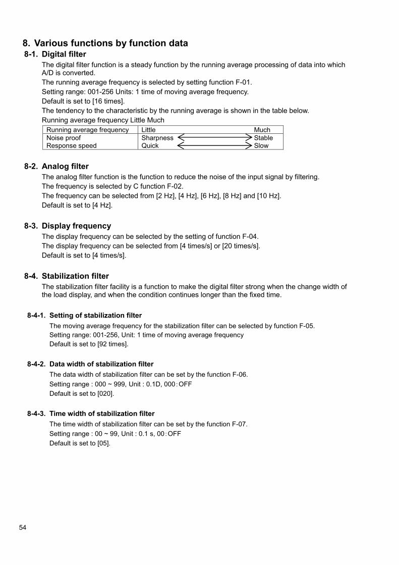
54
8. Various functions by function data 8-1. Digital filter
The digital filter function is a steady function by the running average processing of data into which A/D is converted.
The running average frequency is selected by setting function F-01.
Setting range: 001-256 Units: 1 time of moving average frequency.
Default is set to [16 times].
The tendency to the characteristic by the running average is shown in the table below.
Running average frequency Little Much
Running average frequency Little Much
Noise proof Response speed
Sharpness Stable Quick Slow
8-2. Analog filter
The analog filter function is the function to reduce the noise of the input signal by filtering.
The frequency is selected by C function F-02.
The frequency can be selected from [2 Hz], [4 Hz], [6 Hz], [8 Hz] and [10 Hz].
Default is set to [4 Hz].
8-3. Display frequency
The display frequency can be selected by the setting of function F-04.
The display frequency can be selected from [4 times/s] or [20 times/s].
Default is set to [4 times/s].
8-4. Stabilization filter
The stabilization filter facility is a function to make the digital filter strong when the change width of the load display, and when the condition continues longer than the fixed time.
8-4-1. Setting of stabilization filter
The moving average frequency for the stabilization filter can be selected by function F-05.
Setting range: 001-256, Unit: 1 time of moving average frequency
Default is set to [92 times].
8-4-2. Data width of stabilization filter
The data width of stabilization filter can be set by the function F-06.
Setting range : 000 ~ 999, Unit : 0.1D, 000:OFF
Default is set to [020].
8-4-3. Time width of stabilization filter
The time width of stabilization filter can be set by the function F-07.
Setting range : 00 ~ 99, Unit : 0.1 s, 00:OFF
Default is set to [05].

55
[Example] The data width to which the stabilization filter is executed is selected by the function F-06.
The data width of the stabilization filter for each set value [n] is obtained in the display conversion by the following expression.
[Data width of stabilization filter] = [Setting value of F-06] x [The scale interval]
When the setting by function F-06 is [10], and the scale interval is [D=5], it will be as follows;
[Data width of stabilization filter] =10 x 5 x 0.1 =5 D
When the change width of the load display is within the value set by function F-06, and when the condition continues for the time for function F-07 or more, the stabilization filter set by function F-05 becomes effective.
When the digital filter is set by function F-01, the moving average process executes [Moving average of stabilization filter function (F-05)], after [The moving average of digital filter(F-01)]
Display
Time
Time width of stabilization filter
Data width of stabilization filter
Load variation width
Time width of stabilization filter
Load variation width
Data width of stabilization width
Digital filter for stabilization filter
ON
OFF
Time width of stabilization filter Load variation width
Data width of
stabilization filter

56
8-5. Key lock function
Lock the key function limit a key operation of front panel for avoids wrong operation of keys.
8-5-1. Key lock 1
The function of F-08 sets whether the key operation of [ON/OFF], [SET], [ACCUM./ ] and [PRESET
TARE/ ] is [valid] or [invalid].
Setting range: 0000-1111, 0 : Invalid, 1 : Valid
100 digit : ON/OFF
101 digit : SET
102 digit : ACCUM./
103 digit : PRESET TARE/
The operation of [SET] key becomes valid only once by pressing [SET] key and [NET/GROSS] key at the same time when the operation of [SET] key is locked.
8-5-2. Key lock 2
The function of F-09 sets whether the key operation of [TARE/ ], [NET/GROSS/ ], [ZERO] or [F/] is [valid] or [invalid].
Setting range: 0000-1111, 0: Invalid, 1: Valid
100 digit: TARE/
101 digit: NET/GROSS/
102 digit: ZERO
103 digit: F/
8-6. Stability detection
When the change width of the load display is within the data width set by function F-10, and when the condition continues for the time set by function F-11 or more, the stability detection is the function to judge the measuring value being stable.
8-6-1. Data width of stability detection
The data width of stability detection can be set by function F-10.
Setting range : 000-999, Unit: 0.1D, 0:OFF
Default is set to [020].
The data width is obtained in the display conversion by the below formula.
[Data width of stability detection] = [Setting value of F-10] x 0.5 x [The scale interval]
When the setting of function F-10 is [5], and when the scale interval is [D = 2], it will become as follows;
[Data width stability detection] = 5 x 0.1 x 2 = 1D
8-6-2. Time width of stability detection
The time width of stability detection can be set by function F-11.
Setting range : 00-99, Unit : 0.1 s, 0:OFF
Default is set to [10].
When two range or three range switches have been selected by the automatic range switches, the data width of the stability detection execute the display conversion of the data width by the value of the first range scale interval (scale interval in the calibration).

57
8-7. Input of the preset tare weight cancellation
The preset tare weight cancellation function executes the tare weight cancellation according to the set value by which digital is input.
8-7-1. Operating condition of the preset tare weight cancellation
The preset tare weight cancellation can be selected as [Effective], [Invalid], or [Net weight offset operation], using function F-15. Default is set to [Effective].
8-7-2. Input of the preset tare weight cancellation
By pressing the key from the normal measurement mode, you can see the input display for setting the preset tare weight cancellation. As the value being memorized now is displayed while the tare weight cancellation is setting, please set the value of preset tare weight cancellation by using the following keys.
: Change the value of changing digit.
: Select the changed digit.
: Change the display value into [0].
: The displayed value is not memorized, and it returns to the measurement mode.
: Memorize the display value and proceed to the next step.
: The display is turned off without changing all setting, and it becomes the stand-by condition. After changing, the F key is pressed. A preset tare weight cancellation is executed, the load display becomes [Net value =
Gross value – preset tare weight setting value], and [PRESET]
and [NET] of the status display lights.
・ If the preset tare weight cancellation is set as [Effective] and automatic range switching is set, the
setting range in which a preset tare weight cancellation can be input is within the first range.
・ If preset tare weight cancellation is set as [Effective] and when preset tare weight cancellation is executed while tare weight cancellation is being executed, tare weight cancellation will be cancelled and preset tare weight cancellation will be executed.
・ If preset tare weight cancellation is set as [Effective] and when the zero set is executed with the gross value displayed, the preset tare weight cancellation will be cleared.
8-7-3. Net weight offset operation
If preset tare weight cancellation is set as [Net weight offset operation] and when the zero set is executed with gross value displayed, the net weight offset will not be cleared. The resulting value after subtracting the net weight offset from the gross weight will be the net weight.
・ If preset tare weight cancellation is set as [Net weight offset operation] and when preset tare weight
cancellation is executed while tare weight cancellation is being executed, the net weight offset operation will not be executed. (The tare weight cancellation function takes priority over the net weight offset operation.)
Measurement mode
Measurement mode

58
8-8. Print command
Execute the setting of print operation of manual and automatic, manual printing operation is used when the print operation is executed by the method either setting the F key to print or using the external control I/O.
Automatic print operation is used to print out automatically at every time when load on a weighing section is measured by using a 2-wires method serial interface, BCD output interface or RS-422/485 interface.
8-8-1. Print operation status
The print operation status is selected by function F-16.
Setting range: 00-11
100 digit: manual print operation effective only in the stable.
[0]: Effective only in the stable. [1]: Always effective
101 digit: Automatic print operation.
[0]: Turn off the automatic printing. [1]: Automatic printing in the stable.
[00] is selected as default. Print by ‘Print input’ with setting or external control I/O.
8-9. Hold
This function retains the various data of a load display value, a comparison result, a CC-link interface and a serial interface while measuring.
The hold signal can input by setting the into hold or by using the external control I/O.
8-9-1. Hold operation
Select the hold operation status by function F-17.
Hold operation status is selectable from [Synchronizing with Hold] or [Synchronizing with Batch Finish]
Default is set to [Synchronizing with Hold].
8-9-2. Hold target
(1) Hold of load display value
Whether valid or invalid of holding operation of load display value is selected by the setting of 100 digit of F-18.
Default is set to [Valid].
The load display section changes into the error display of [OL] or [OVF] when [OL] or [OVF] error occurs while the holding operation of load display value.
(2) Hold of comparison result
Whether valid or invalid of holding operation of comparison result is selected by the setting of 101 digit of F-18. Default is set to [Invalid].
The holding targets of the simple comparison mode and the sequential mode are the signals of [Full Flow], [Medium Flow], [Dribble Flow], [Over], [OK], [Under], [Full] and [Near Zero].
The holding targets of the 4-steps comparator mode are the signals of [S1], [S2], [S3], [S4], [Full] and [Near Zero].
The condition data of a condition display, I/O output, Standard RS-485, RS-232C, RS-422/485 and CC-link corresponding to the holding target of comparison result is also held during the holding operation of comparative result.

59
(3) Hold of CC-Link interface
Whether valid or invalid of holding operation of output data by optional CC-Link interface is selected by the setting of 103 digit of F-18. Default is set to [Invalid].
The holding target when the setting of occupied station for CC-Link interface is selected by 4 stations is [Gross value] and [Net value].
The holding target in the selection of 2 or 1 station(s) is [Display value (Net value /Gross Value)].
The data of holding target retains holding condition even if the error of [OL] or [OVF] occurs in the holding operation of CC-Link interface. However, the occurrence of [OL] or [OVF] error can be detected by the signal of [Abnormal weight].
(4) Hold of 2 wires method serial interface
Whether valid or invalid of holding operation of output data by 2-wires method serial interface is selected by the setting of 104 digit of F-18.
Default is set to [Invalid].
Holding target is [Gross value], [Net value], [Tare weight cancellation value], [Gross value condition], [Net value condition], [Tare weight canceling condition], [Stable condition], [Center zero condition] and [Fired tare weight condition].
The data of holding target retains holding condition even if the error of [OL] or [OVF] occurs in the holding operation of 2-wires method serial interface. However, the occurrence of [OL] and [OVF] error can be detected by the signal of [OVR].
8-10. Sub display section
The value displayed at sub display section is selected.
8-10-1. Select the display of sub display section
The value displayed at sub display section is selected by function F-19.
Setting range: 0 to 20
0 : OFF
1 : A Brand (1 digit) / Accumulation times (6 digits) / Accumulation value (8 digits)
2 : B Brand (1 digit) / Accumulation times (6 digits) / Last accumulated data (6 digits)
3 : C Brand (1 digit) / Last accumulated data (6 digits) / Accumulation value (8 digits)
4 : D Brand (1 digit) / Last accumulated data (6 digits) / OK (6 digits)
5 : E Brand (1 digit) / Accumulation times (6 digits) / OK (6 digits)
6 : F Brand (1 digit) / OK (6 digits) / Accumulation value (8 digits)
7 : G Brand (1 digit) / Near zero (6 digits) / Full (6 digits)
8 : OK (6 digits) / Over (5 digits) / Under (5 digits)
9 : I Brand (1 digit) / OK (6 digits) / Free fall (6 digits)
10 : J Brand (1 digit) / S1 (6 digits) / S2 (6 digits)
11 : K Brand (1 digit) / S1 (6 digits) / S3 (6 digits)
12 : L Brand (1 digit) / S1 (6 digits) / S4 (6 digits)
13 : M Brand (1 digit) / S2 (6 digits) / S3 (6 digits)
14 : N Brand (1 digit) / S2 (6 digits) / S4 (6 digits)
15 : O Brand (1 digit) / S3 (6 digits) / S4 (6 digits)
16 : P Brand (1 digit) / OK (6 digits)
17 : Q Brand (1 digit) / Over (5 digits) / Under (5 digits)
18 : R Brand (1 digit) / Accumulation times (6 digits)
19 : S Brand (1 digit) / Accumulation value (10 digits)
20 : T Brand (1 digit) / Last accumulated data (6 digits)
Default is set to [0: OFF].

60
8-11. Accumulation
The accumulation function accumulates the load data.
Memorize the accumulation times, updated accumulation data and accumulation value
8-11-1. Operating condition for accumulation function
Operating condition for accumulation function is selected by function F-50.
Setting range: 000-111
100 digit: Accumulation command operation [0] Only at stable condition, [1] Always
101 digit: Automatic accumulating operation [0] OFF, [1] Synchronized with end signal, [2] Automatic accumulation in stable
102 digit: Automatic accumulating condition [0] Only in OK condition, [1] with no condition
Default is set to [000].
8-11-2. Execute accumulation
(1) Manual accumulation
When the value set with 100 digit for F-50 is
0: the accumulation is executed by pressing key under the condition that the stability sign of status display is lights.
1: the accumulation is executed by pressing key regardless of lighting on or off the stability sign.
(2) Automatic accumulation
When the value set with 101 digit for F-50 is:
0: automatic accumulation does not work.
1: accumulation works automatically synchronizing with finish signal.
2: accumulation works automatically under the condition that the stability sign of status display lights.
Also, when the value set with 102 digit for F-50 in the condition that [1] is set with 101 digit for F-50 is:
0: accumulation works automatically in the condition that the finish signal outputs under lighting on sign of OK in the status display.
1: accumulation works automatically in the condition that the finish signal output regardless of lighting on or off the OK sign.
・ If the results exceed the display range of the accumulation value or accumulation times,
accumulation is not executed. The status display [ACCUM.] mark blinks.
・ Accumulating is prohibited if the result exceeds ±100% of the weighing capacity.
8-11-3. Display range of the accumulated value and count
The display range of the accumulation value is from –9 999 999 999 to 9 999 999 999.
The display range of the accumulated count is from 0 to 999 999.
The upper limit of accumulated value disregards the displayed decimal point.
Example. When the position of decimal point is 0.0, the upper limit of accumulated value is 9 999 999 99.9.
When the accumulated value and the accumulated count exceeding the display range results, the additive of the count is not executed. As the error code display at sub display, please execute to clear the accumulated value and count.

61
8-11-4. The clear of accumulation value / the accumulation times
Clear the accumulation value and the accumulation times.
There are four methods for accumulating as follows.
● Press the key in accumulation display mode.
● Set a key to [Accumulation clear] by setting F-55.
● Clear all brand accumulation by setting external control I/O.
● Clear all brand accumulation using SQ function SQF-98.
For details of accumulation display mode, see "Clause 3-1".
For details of SQ function setting, see "Clause 10".
8-12. Brands
Brand comparison values can be set for individual brand numbers.
Weighing is controlled using the various brand settings to ensure the target (OK) weight is achieved.
The CSD-903 is capable of storing up to eight different brands.
For details of the settings available for brands, see "9. Measurement mode".
8-12-1. Target of brand changeover
The brand number can be changed using function, external control input, or communication.
The changeover method enabled when changing the brand number is selected using the function F-51 setting.
To change the brand number in EzCTS mode, set function F-51 to [0: Changeover by function].
Setting range: 0 to 3
0: Changeover by function
The brand number can be changed by changing the function F-52 setting.
To change the brand number using standard RS485, RS-232C, or RS-422/485, change the brand number using the communication command [@007052].
For details of communication commands, see "16-3-12. Data format of command mode".
1: Changeover by external control input
Brand number changeover can only be enabled using external control input. If changeover by external control input has been selected, see "8-14. Setting of external control input".
2: Changeover by communication
This enables brand number changeover using the communication command [@0069].
For details of communication commands, see "16-3-12. Data format of command mode".
Default is set to [Changeover by key operation].
8-12-2. Brand number
The brand number enabled by measurement control is selected using function F-52.
Brand numbers 0 to 7 can be selected.
Default is set to [Brand No. 0].
8-13. Setting of F key
Operation of F key can be selected by function F-55.
Setting range: 0 ~ 9
0: OFF No setting
1: Print Input the print signal
2: Hold Input the holding signal
3: Batch start Input the signal to start batch
4: Emergency stop Input the signal to emergency stop

62
5: Zero clear Return the condition of display before the zero set and zero tracking when the zero set or the zero tracking executed
6: Tare clear Execute the tare weight cancellation
7: Accumulation clear Clear the accumulation value and times
8: Measurement comparison Move to Measurement comparison value setting mode
9: Forced batch finish Complete the weighing operation compulsorily
8-14. Setting of external control I/O
Set the external control I/O which I/O connecter is mounted at rear panel of this instrument.
8-14-1. Setting method of the external control input
The operation of an external control input is selected by setting function F-60 to F-68.
Setting range: 00 ~ 23
0: OFF No setting
1: ON/OFF key The same operation as the ON/OFF key
2: Setting key The same operation as the Setting key
3: Accumulation key The same operation as the Accumulation key
4: Preset tare key The same operation as the Preset tare key
5: Tare key The same operation as the Tare key
6: Gross/Net key The same operation as the Gross/Net key
7: Zero key The same operation as the Zero key
8: F key The same operation as the F key
9: Zero clear Return the condition of display before the zero set and zero tracking when the zero set or the zero tracking executed
10: Tare clear Return the condition of display before the tare weight cancellation when the tare weight cancellation is executed.
11: Batch start Input the signal to start batch
12: Discharge start Input the signal to discharge batch
13: Changeover the flow and discharge Changeover the measuring mode flow and discharge
(ON: Discharge, OFF: Batch)
14: Clear the last accumulated data Clear the last accumulated data
15: Accumulation clear Clear the accumulation value and the accumulation times
16: Error cancellation Cancel the Error
17: Print Input the print signal
18: Hold Input the holding signal
19: Emergency stop Input the emergency signal
20: Manual free fall compensation Do the free fall compensation
21: Display of Net Display changes to Net of the load display.
22: Finish the weighing data compulsorily Input the signal to finish the weighing data compulsorily
23: Finish the flow compulsorily Input the signal to finish the flow compulsorily
24: All brand accumulation clear Clear the accumulation value and accumulation times for all brands
25: Brand 1 Input brand number using BCD code
26: Brand 2 Input brand number using BCD code
27: Brand 4 Input brand number using BCD code
Default is set to [OFF]
The following items are level input, and become effective at the input of the shortening of 50 ms or more.
[13: Changeover the flow and discharge], [18: Hold], [21: Display of Net]
Other items are pulse input, and become effective once at the pulse input of over 50 ms or more.

63
8-14-2. Setting method of the external control output
The operation of the external control output is selected by setting function F-70 to F-82.
Setting range: 00 ~ 22
0 : OFF No setting
1 : STABLE Output during stable.
2 : DURING TARE Output when the tare weight cancellation is executed.
3 : GROSS DISPLAY Output when the display is the gross value.
4 : NET DISPLAY Output when the display is the net value.
5 : CENTER OF ZERO Output in the condition of the center zero.
6 : DURING HOLD Output during the holding operation is made.
7 : ERROR Output when the error is occurred.
8 : ABNORMAL WEIGHT Output when display is OL
9 : WEIGHING Sequence ERROR Output when the sequence error is caused.
10 : NEAR ZERO Output in near zero.
11 : OK/S0 When the judgment condition becomes ok in sequential mode.
Also when an output signal S0 is ‘ON’ status in 1 or 2 of comparator mode.
12 : F.FLOW/S1 When a output signal of full flow is [ON] status in sequential mode.
Also when an output signal S1 is [ON] status in 1 or 2 of comparator mode.
13 : M.FLOW/S2 When a output signal of medium flow is [ON] status in the sequential mode. Also when an output signal S2 is [ON] status in 1 or 2 of comparator mode.
14 : D.FLOW/S3 When a output signal of dribble flow is [ON] status in the sequential mode. Also when an output signal S3 is [ON] status in 1 or 2 of comparator mode.
15 : OVER/S4 When the judgment condition becomes over in sequential mode.
Also when an output signal S4 is [ON] status in 1 or 2 of comparator mode.
16 : UNDER When the judgment condition becomes under in sequential mode.
17 : FULL When the judgment condition becomes full in sequential mode.
18 : During measuring Output during measuring.
19 : BATCH FINISH Output in finishing the measurement.
20 : DISCHARGE (GATE OPEN) Output in executing the discharge.
21 : DISCHARGE FINISH Output in the finish of discharge.
22 : RUN Output during measuring mode.
Default is set to [OFF].
8-15. Memory clear
Memory clear is executed by function F-99.
The setting content of the function is returned to the default setting.
When the key is pressed with displayed, becomes a blinking display.
At this time, please press the key to discontinue a clear memory.
It becomes a stand-by mode, and a clear memory is not executed.
When is a blinking display, the display section is turned off by pressing the key,
and it becomes display, the operation of memory clear is completed.
Please do not clear the memory under the measurement to cause an unexpected malfunction.

64
9. Measurement mode CSD-903 consists of four measurement modes. Please set it with [Clause 9-1].
In addition, please set each measurement comparison value in referring to [Clause 9-2].
Furthermore, there are two control modes about [Simple comparative mode], [Sequential mode], and they divide to [Batch mode], and [Discharge mode].
Please control the supply of the raw material to the measurement hopper while observing the full amount output by PLC etc.
CSD- 903
1)Simple comparison mode
2)Sequence mode
3)4 steps comparator mode 1
Batching mode
Discharge modeBatching mode
Discharge mode
4)4 steps comparator mode 2
Supply gate
Full・Medium・Dribble flow
Measurement hopper
Raw material
Lode cell
Container
Discharge gate
Full amount output
Programmable logic controller
F・F
M・F
D・F
Examp le for measuring by discharge mode
Raw material
Discharge gate
Batch gate
Container
Lode cell
Discharge
Example for measuring by batch mode
Full・Medium・Dribble flow
Measurement hopper

65
The outline of each mode is as follows.
(1) Simple comparison mode
A set value and measured value are compared and whenever the comparative result satisfies the condition, the output turns on. When the gate control etc., are required, PLC etc., are needed.
As for the comparison and the judgement condition, refer to each paragraph in [9-3.Simple comparison mode].
(2) Sequential mode
The comparison of the measured value without connecting PLC, etc., outside, and the control that sets up the order of the gate control etc., can be worked.
As a result, system construction that omits PLC becomes possible. In this mode, each output is turned ON, according to the value of each brand set with the on edge (OFF→ON) of start signal. If the set value is compared with the measurement value, and the comparison result satisfies it, then the output becomes OFF. If the output is turned OFF once in this mode, the output is turning off until the completion signal is output, even when the comparison results become out of the condition. Refer to each paragraph of in [9-4.Sequential mode]. In this mode, you can control in order without connecting the sequencer etc. externally.
(3) 4 steps comparator mode 1
Compare a set value and the measured value, and output the comparative result.
With four steps comparator modes 1, Turning ON or OFF the output is decided on the condition of [Under] or [Over] after comparing with a measuring value and the set value 1.
Please refer to each clause of [Clause 9-5] for more information about movement.
(4) 4 steps comparator mode 2
With four steps comparator mode 2, it is suitable for sorting measurements because the output twins on when a measurement value enters within two set points.
Please refer to each clause of [Clause 9-6] for more information about movement.

66
9-1. Setting method of the measurement mode
Change from the standard measurement mode to the
display by the key.
Pressing the key, it displays and enters the mode of SQ function.
By pressing the key, is displayed. Please select SQ function number which you want to change
: The value of changed digit is changed.
: Changed digit is selected.
: The displayed value is changed to [0].
: Display returns to .
: The display value is memorized, and it proceeds to the next step.
: The SQ function mode is finished without changing all setting.
Please press the key, and set the setting value of the selected SQF-01.
Please press the key. The setting content is registered, and the display panel displays the following registered SQ function number. Please continue and select the selected SQ function number when you change setting of other SQ function numbers.
If the key is pressed after registration is completed, it becomes
display. Please set to the measurement mode by
pressing the key.
Please do not change in the set value under the measurement because the A/D sampling rate decreases temporarily while rewriting the set value.
Measurement mode
Measurement mode

67
9-2. Measurement comparison value setting mode
The set value in which each measurement operation in executed in the measurement comparison value setting mode is set.
By a selected measurement mode, setting content is different.
9-2-1. Measurement comparison value 1 setting mode
The measurement comparison value used in simple comparison mode and sequential mode is set
(1) Setting method of measurement comparison value 1 setting mode
Change from the standard measurement mode to the
display by the key.
is displayed after pressing the key twice, and enter into the measurement comparison value 1 setting mode.
By pressing the key, is displayed. At this time, the corresponding display blinks linked to the display for SET1 to SET8 and B0 to B7.
: The value of changed digit is changed.
: Changed digit is selected.
: Display returns to .
: The display value is memorized, and it proceeds to the next step.
Please press the key, and set the setting value of the selected comparison value. At this time, the condition display that becomes an object along with the setting of SET1 to SET8 blinks.
Please press the key. The setting content is registered and the display panel displays the following registered measurement comparison value number. Please continue and select the selected measurement comparison value number when you change setting of other measurement comparison value number.
If the key is pressed after registration is completed, it becomes
display. Please set to the measurement mode by
pressing the key.
Please do not change in the set value under the measurement because the A/D sampling rate decreases temporarily while rewriting the set value. Please set the storing place to the internal ROM when you change the set value during the measurement.
Measurement mode
Measurement mode

68
(2) Function of the data of measurement comparison value 1
Item Set data No. Set value Contents
FINAL SET1 000000 ~ 999999
●000000
Unit : 1D
FREE FALL SET2 -999999 ~ 999999
●000000
Unit : 1D
PRELIMINARY 1 SET3 000000 ~ 999999
●000000
Unit : 1D
PRELIMINARY 2 SET4 000000 ~ 999999
●000000
Unit : 1D
OVER SET5 000000 ~ 999999
●000000
Unit : 1D
UNDER SET6 000000 ~ 999999
●000000
Unit : 1D
ZERO BAND SET7 000000 ~ 999999
●000000
Unit : 1D
FULL SET8 000000 ~ 999999
●000000
Unit : 1D
● Has been set as default
● Brand number
Set the brand number.
The brand number can be changed by pressing the key or key when is displayed.
Setting range: 0 to 7 Unit: 1D
Default is set to [0].
● FINAL
Set the target value for the measurement.
Setting range:000000-999999 Unit:1D
Default is set to [000000].
● FREE FALL
Set the target value for the free fall.
Setting range:-999999-999999 Unit:1D
Default is set to [000000].
In the simple comparison mode, when the value of [FINAL (SET1) – F.FALL (SET2)] is obtained the D.FLOW output will be ON, and in the sequential mode the D.FLOW will be OFF when arrived at the value of D.FLOW.
The setting is [FINAL ≦ F.FALL], it becomes SQ.ERR 3. When the start signal is in putting,
● PRELIMINARY 1
Set the value of PRELIMINARY 1.
Setting range:000000 ~ 999999 Unit:1D
Default is set to [000000].
In the sequential mode, when the value of [FINAL (SET1)– PRELIM 1(SET3)] is obtained the M.FLOW output will be ON, and in the Simple comparative mode the D.FLOW will be OFF when arrived at the value of M.FLOW.
When the start signal is inputting, the setting is [FINAL≦F.FALL], it becomes SQ.ERR 3.
one before ≧ of 1 or the head is measured before the setting measures fixed quantity ≦
PRELIM1.

69
● PRELIMINARY 2
Set the value of PRELIMINARY 2.
Setting range:000000-999999 Unit:1D
Default is set to [000000].
In the sequential mode, when the value of [FINAL(SET1) – PRELIM 2(SET4)] is obtained the F.FLOW output will be ON, and in the simple comparative mode the F.FLOW will be OFF when arrived at the value of [FINAL(SET1) – PRELIM 2(SET4)].
When the setting is [FINAL ≧ PRELIM 2] , [PRELIM 1 ≧ PRELIM 2] or [F.FLOW ≦ PRELIM 2], it
becomes SQ.ERR 3 at the time of start signal is inputting.
● OVER
Set the value of OVER.
Setting range:00000-99999 Unit:1D
Default is set to [00000]
When the measurement result [FINAL (SET1) + OVER (SET5)] is exceeded, the over output is turned on.
● UNDER
Set the value of UNDER.
Setting range:00000-99999 Unit:1D
Default is set to [00000].
When the measurement result [FINAL (SET1) - UNDER (SET6)] is exceeded, the under output is turned on.
● ZERO BAND
Set the value of Near zero.
Setting range:00000-99999 Unit:1D
Default is set to [00000].
When the measurement result is under the value of [FINAL (SET1) - OVER (SET5)], the under output will be on.
● FULL
Set the value of FULL.
Setting range:000000-999999 Unit:1D
Default is set to [000000]
When the Gross weight or the Net weight exceeds the Full value, the FULL output will be ON.
Please set the stored place to the internal RAM when the set value is continuously changed, and the rewritable time of EEPROM might exceed about one million times.

70
9-2-2. Measurement comparison value 2 setting mode
The measurement comparison value used in four steps of comparator modes 1 and 2.
(1) Setting method of measurement comparison value 2 setting mode
Change from the standard measurement mode to the
display by the key.
is displayed after pressing the key twice, and enter into the measurement comparison value 2 setting mode.
By pressing the key, is displayed. Change this number which you set. At this time, the corresponding display blinks linked to the display for S1 to S4, SET7, SET8, and B0 to B7.
: The value of changed digit is changed.
: Changed digit is selected.
: Display returns to .
: The display value is memorized, and it proceeds to the next step.
Please press the key, and set the setting value of the selected comparison value.
Please press the key. The setting content is registered and the display panel displays the following registered measurement comparison value number. Please continue and select the selected measurement comparison value number when you change setting of other measurement comparison value number.
If the key is pressed after registration is completed, it
becomes display. Please set to the
measurement mode by pressing the key.
Please do not change in the set value under the measurement because the A/D sampling rate decreases temporarily while rewriting the set value. Please set the storing place to the internal ROM when you change the set value during the measurement.
Measurement mode
Completing registration.
Measurement mode

71
(2) Function of the data of measurement comparison value 2
Item Set data No. Set value Contents
S1 S1 -999999~999999
●000000
Unit : 1D
S2 S2 -999999~999999
●000000
Unit : 1D
S3 S3 -999999~999999
●000000
Unit : 1D
S4 S4 -999999~999999
●000000
Unit : 1D
Near zero SET7 000000~999999
●000000
Unit : 1D
FULL SET8 000000~999999
●000000
Unit : 1D
● Brand number
Set the brand number.
The brand number can be changed by pressing the key or the key when is displayed.
Setting range: 0 to 7 Unit: 1D
Default is set to [0].
● S1 to S4
Set the value of comparator
Setting range:-999999-999999 Unit : 1D
Default is set to [000000].
Operation for value is referring to 9-9. and 9-10.
● Near zero (ZERO BAND)
Set the value that can output the signal of near zero.
Setting range:000000-999999 Unit : 1D
Default is set to [000000].
When the measurement result is under the value of (fixed value-over) , the under output will be on.
● FULL
Set the value of FULL.
Setting range:000000-999999 Unit : 1D
Default is set to [000000].
When the Gross weight or the Net weight exceeds the Full value, the FULL output will be ON.
Please set the stored place to the internal RAM when the set value is continuously changed, and the rewritable time of EEPROM might exceed about one million times.

72
9-3. Simple comparison mode
The simple comparison mode includes the simple comparison batching mode and the simple comparison discharge mode.
To set the simple comparison mode, set in [9-9].
To set the batch mode and the discharge mode, set in [9-9].
9-3-1. Simple comparison batching mode
The simple comparison batching mode is a mode to output when the judgment condition is satisfied after comparing the increased value of measured value and set value of each brand at the time of measuring object is batching.
Judgment condition
Status display Judgment condition
Z-BAND |Gross weight or (Net weight) |≦ ZERO BAND (SET7).
F. FLOW Net weight ≧ [Final (SET1) – Prelim 2 (SET4) ]
M. FLOW Net weight ≧ [Final (SET1) – Prelim 1 (SET3) ]
D. FLOW Net weight ≧ [Final (SET1) – Free Fall (SET2) ]
UNDER Net weight < [Final (SET1) – Under (SET6)]
OVER Net weight > [Final (SET1) + Over (SET5)]
OK [Final (SET1) – Under (SET6) ≦ Net weight ≦ Final (SET1) + Over (SET5) ]
Operating explanation
1) When the - net weight becomes the value of [Final value - Prelim 2] the output of Full flow will be ON. And when the start signal is applied, the comparison among Full flow, Medium flow and Dribble flow will be prohibited during the Medium flow comparison prohibited time.
2) When the - net weight becomes the value of [Final value - Prelim 1] the output of Medium flow will be ON. And when the start signal is applied, the comparison among Full flow, Medium flow and Dribble flow will be prohibited during the Dribble flow comparison prohibited time.
3) When the net weight becomes [Final – Free Fall], then the output of Dribble flow will be ON
4) When the start signal is used, the completion signal will be output.
● The comparative target of near zero and the comparative target of FULL value can be selected from Gross weight and Net weight.
● Under, Over and OK can be operated with Net weight. The comparison operation can be changed to simple comparison.
● At the time of setting [Prelim 2=0], the Full flow becomes OFF and at the time of setting [Prelim 1=0], becomes Medium flow OFF.
・ In the case of no use of Start signal, each Condition display will become ON/OFF according to the
Judgment condition shown above.
・ Renewing the output of each condition display is synchronizing with A/D sampling rate.
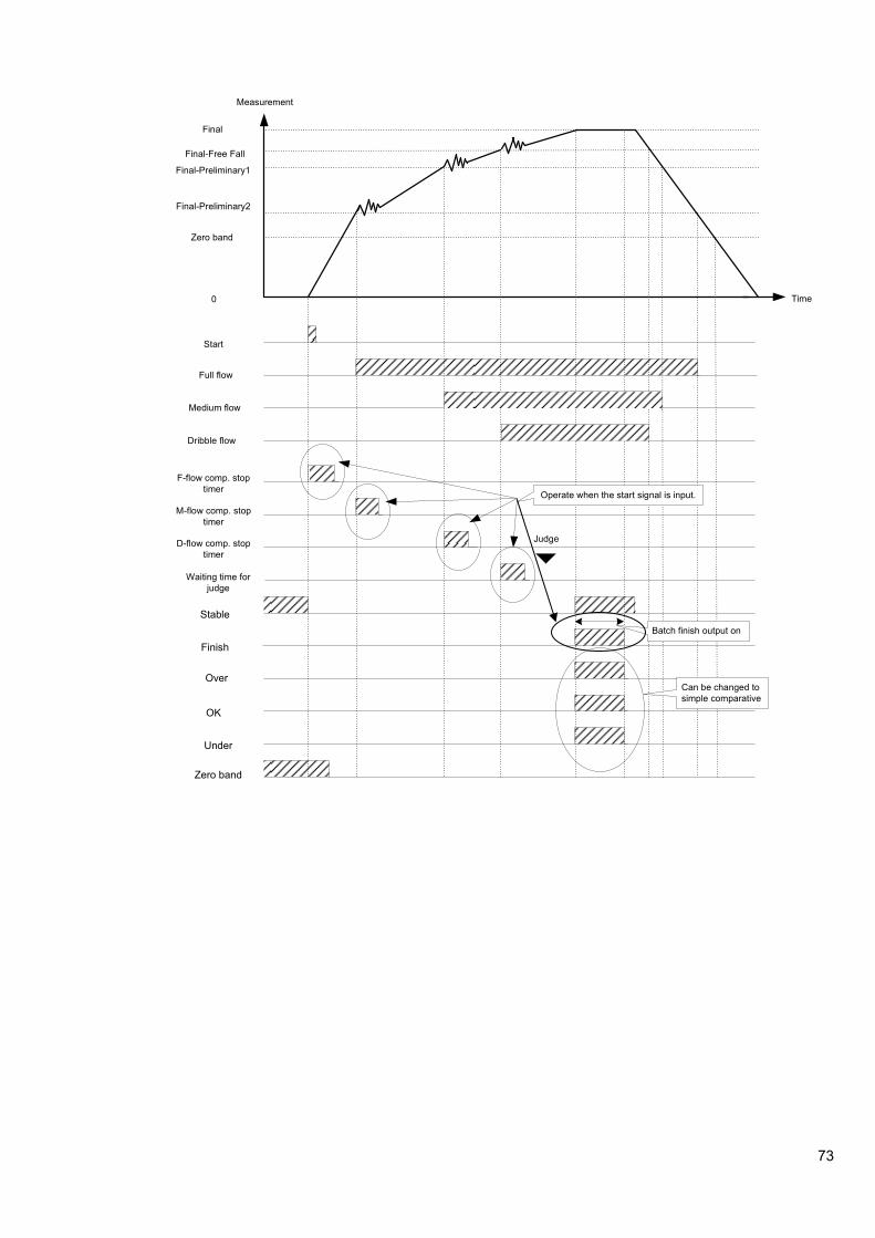
73
Final-Preliminary2
Final-Preliminary1
Final-Free Fall
Final
Full flow
Medium flow
Dribble flow
Waiting time for
judge
Stable
Finish
Measurement
Time
M-flow comp. stop
timer
D-flow comp. stop
timer
Zero band
Over
OK
Under
Zero band
Start
F-flow comp. stop
timer
Judge
0
Operate when the start signal is input.
Batch finish output on
Can be changed to
simple comparative

74
9-3-2. Simple comparison discharging mode
The simple comparison discharging mode is a mode to output when the judgment condition is satisfied after comparing the decreased value of measured value and set value of each brand at the time of measuring object is discharging.
Judgment condition
Status display Judgment condition
Z-BAND |Gross weight or (Net weight) |≦ ZERO BAND (SET7).
F. FLOW - Net weight ≧ [Final (SET1) – Prelim 2 (SET4) ]
M. FLOW - Net weight ≧ [Final (SET1) – Prelim 1 (SET3) ]
D. FLOW - Net weight ≧ [Final (SET1) – Free Fall (SET2) ]
UNDER - Net weight < [Final (SET1) – Under (SET6)]
OVER - Net weight > [Final (SET1) + Over (SET5)]
OK [Final (SET1) – Under (SET6) ≦ - Net weight ≦ Final (SET1) + Over (SET5) ]
Operating explanation
1) When the - net weight becomes the value of [Final value - Prelim 2] the output of Full flow will be ON. And when the start signal is applied, the comparison among Full flow, Medium flow and Dribble flow will be prohibited during the Medium flow comparison prohibited time.
2) When the - net weight becomes the value of [Final value - Prelim 1] the output of Medium flow will be ON. And when the start signal is applied, the comparison among Full flow, Medium flow and Dribble flow will be prohibited during the Dribble flow comparison prohibited time.
3) When the - net weight becomes [Final – Free Fall], then the output of Dribble flow will be ON.
4) When the start signal is used, the completion signal will be output.
● The comparative target of near zero and the comparative target of FULL value can be selected from Gross weight and Net weight.
● Under, Over and OK can be operated with Net weight. The comparison operation can be changed to simple comparison.
● At the time of setting [Prelim 2=0], the Full flow becomes OFF and ant the time of setting [Prelim 1=0], becomes Medium flow OFF.
・ In the case of no use of Start signal, each Condition display will become ON/OFF according to the
Judgment condition shown above.
・ Renewing the output of each condition display is synchronizing with A/D sampling rate.

75

76
9-4. Sequential mode
The sequential mode includes the sequential batching mode and the sequential discharge mode.
Moreover, Supplementary batching, Initial batching, Nuzzle batching and automatic free flow compensation can be set if necessity requires.
9-4-1. Sequential batching mode
The sequential batching mode is a mode to control the measurement sequence depending to the increased value of measuring value when the raw material is batching in.
Judgment condition
Status display Judgment condition
Z-BAND |Gross weight or (Net weight) |≦ ZERO BAND (SET7).
F. FLOW Net weight ≧ [Final (SET1) – Prelim 2 (SET4) ]
M. FLOW Net weight ≧ [Final (SET1) – Prelim 1 (SET3) ]
D. FLOW Net weight ≧ [Final (SET1) – Free Fall (SET2) ]
UNDER Net weight < [Final (SET1) – Under (SET6)]
OVER Net weight > [Final (SET1) + Over (SET5)]
OK [Final (SET1) – Under (SET6) ≦ Net weight ≦ Final (SET1) + Over (SET5) ]
Operating explanation
1) When the start signal is input, the Full flow, Medium flow and Dribble flow will be ON. Moreover, tare weight cancellation is provided with the input of start signal with the setting at the same time.
2) When the net weight becomes [Final value – Prelim 2], the output of Full flow becomes OFF.
3) When the net weight becomes [Final value – Prelim 1], the output of Medium flow becomes OFF.
4) When the net weight becomes [Final value – Free Fall], the output of Dribble flow becomes OFF.
● The comparative target of near zero can be selected from Gross weight and Net weight.
● The near zero will become simple comparison operation.
● The Full flow, Medium flow and Dribble flow will never become ON until the next start signal will be input, once it becomes OFF.
● Under, Over and OK can be operated with Net weight. The comparison operation can be changed to simple comparison.
● At the time of setting [Prelim 2=0], the Full flow becomes OFF and at the time of setting [Prelim 1=0], Medium flow becomes OFF.
● When making the automatic tare cancellation at the time of flow start, set to [Effective] for [Automatic tare cancellation at the time of flow start] after referring to [9-9. Function of the SQ function data].
Renewing the output of each condition display is synchronizing with A/D sampling.
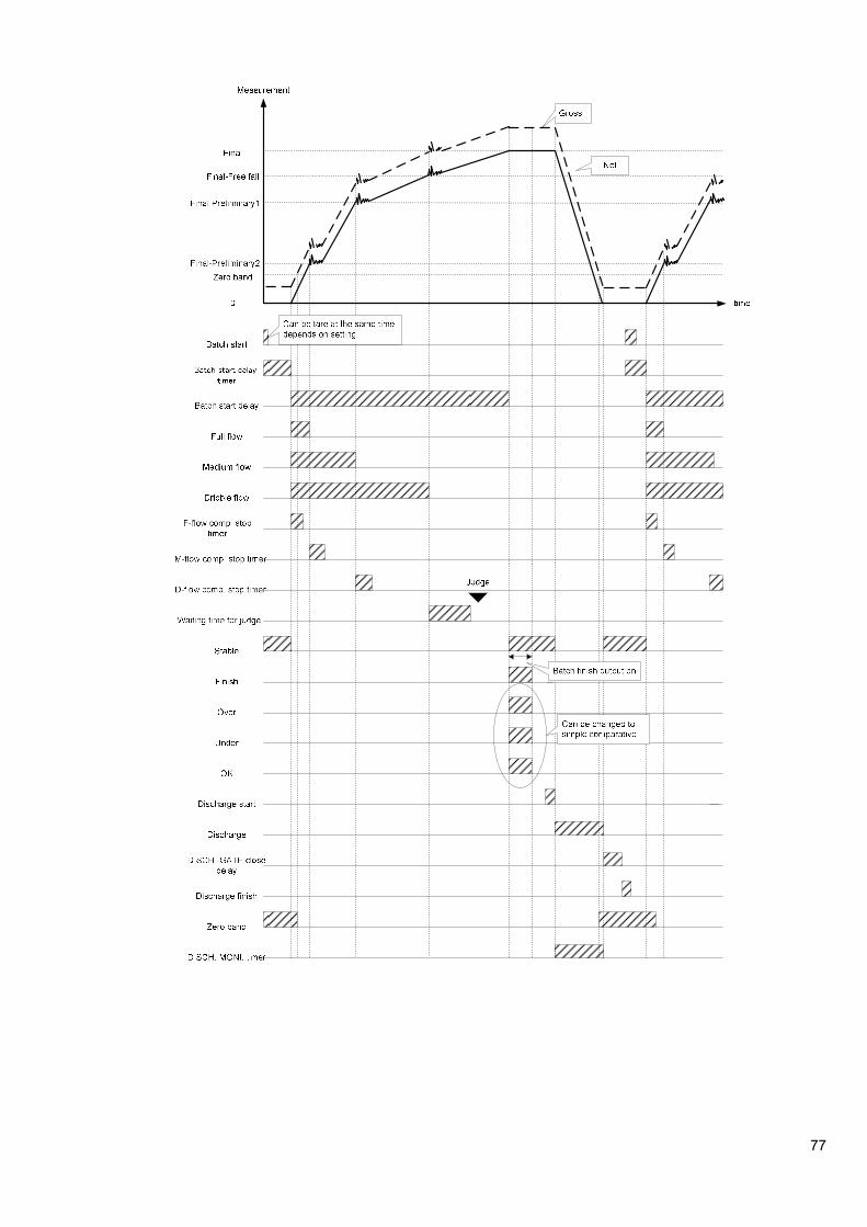
77

78
9-4-2. Sequential batching mode
The sequential batching mode is a mode to control the measurement sequence by the decrease value of measured value when the measuring object is batching out.
Judgment condition
Status display Judgment condition
Z-BAND |Gross weight or (Net weight) |≦ ZERO BAND (SET7).
F. FLOW - Net weight ≧ [Final (SET1) – Prelim 2 (SET4) ]
M. FLOW - Net weight ≧ [Final (SET1) – Prelim 1 (SET3) ]
D. FLOW - Net weight ≧ [Final (SET1) – Free Fall (SET2) ]
UNDER - Net weight < [Final (SET1) – Under (SET6)]
OVER - Net weight > [Final (SET1) + Over (SET5)]
OK [Final (SET1) – Under (SET6) ≦ - Net weight ≦ Final (SET1) + Over (SET5) ]
Operating explanation
1) When the start signal is input, the Full flow, the Medium flow and the Dribble flow turns ON. Moreover, tare weight cancellation is provided with the input of start signal with the setting at the same time.
2) When the net weight is the value of [Final value - Prelim 2], the output of Full flow becomes OFF.
3) When the net weight is the value of [Final value - Prelim 1], the output of Medium flow becomes OFF.
4) When the net weight is the value of [Final – Free Fall], the output of Dribble flow becomes OFF.
● The comparative target of near zero can be selected from Gross weight and Net weight.
● The near zero will become simple comparison operation.
● The Full flow, Medium flow and Dribble flow will never become ON until the next start signal will be input, once it becomes OFF.
● Under, Over and OK can be operated with Net weight. The comparison operation can be changed to simple comparison.
● At the time of setting [Prelim 2=0], the Full flow becomes OFF and at the time of setting [Prelim 1=0], Medium flow becomes OFF.
● When making the automatic tare cancellation at the time of flow start, set to [Effective] for [Automatic tare cancellation at the time of flow start] after referring to [9-9. Function of the SQ function data].
Renewing the output of each condition display is synchronizing with A/D sampling.
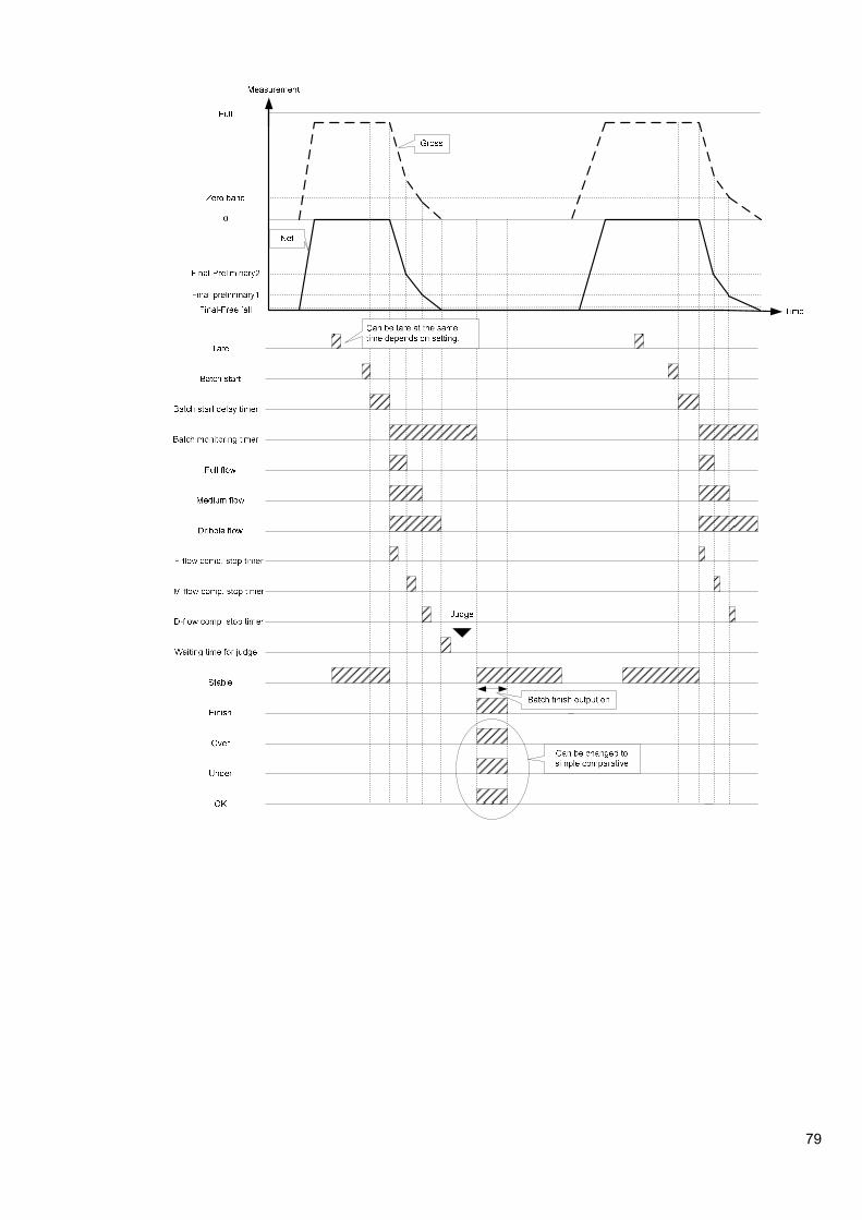
79

80
9-4-3. Supplementary Batch (discharge) mode
Supplementary batch (discharge) is a function to make the Dribble batch ON automatically in fixed time, when the batch (discharge) weight becomes short in the Sequential batch (discharge) mode.
In order to execute supplementary batch (discharge), set the items of [Maximum times of supplementary flow], [Time of supplementary batch] and [Waiting time after supplementary batch] after referring to [9-9. Function of the SQ function data].
Judgment condition
Status display Judgment condition
Z-BAND |Gross weight or (Net weight) |≦ Set value of near zero(SET7).
F. FLOW Net weight ≧ [Final (SET1) – Prelim 2 (SET4) ]
M. FLOW Net weight ≧ [Final (SET1) – Prelim 1 (SET3) ]
D. FLOW Net weight ≧ [Final (SET1) – Free Fall (SET2) ]
UNDER Net weight < [Final (SET1) – Under (SET6)]
OVER Net weight > [Final (SET1) + Over (SET5)]
OK [Final (SET1) – Under (SET6) ≦ Net weight ≦ Final (SET1) + Over (SET5) ]
Operating explanation
1) When the start signal is input, the Full flow, Medium flow and Dribble flow will be ON. Moreover, tare weight cancellation is provided with the input of start signal with the setting at the same time.
2) When the net weight is the value of [Final value – Prelim 2], the output of Full flow becomes OFF.
3) When the net weight is the value of [Final value – Prelim 1], the output of Medium flow becomes OFF.
4) When the net weight is the value of [Final – Free Fall], the output of Dribble flow becomes OFF.
5) After completing the Dribble flow, the supplementary flow starts when the [Under] signal is output in stable time. The time of this supplementary flow will become the set time in SQ function (SQF-35).
6) The supplementary flow can be made with the set times of maximum times of supplementary flow described in the (8-9-2. The item of Sequence control setting). When the Under signal can’t be output at less times than the set value, then the supplementary flow shall be finished at the time.
7) The Under signal is output even if the supplementary flow is applied with the same times of the maximum supplementary flow, it will become the sequence error (SQ ERR2)
● The comparative target of near zero can be selected from Gross weight and Net weight.
● The near zero will become simple comparison operation.
● The Full flow, Medium flow and Dribble flow will never become ON until the next start signal will be input, once it becomes OFF.
● Under, Over and OK can be operated with Net weight. The comparison operation can be changed to simple comparison.
● At the time of setting [Prelim 2=0], the Free flow becomes OFF and at the time of setting [Prelim 1=0], Medium flow becomes OFF.
● When making the automatic tare cancellation at the time of flow start, set to [Effective] for [Automatic tare cancellation at the time of flow start] after referring to [9-9. Function of the SQ function data].
Renewing the output of each condition display is synchronizing with A/D sampling.

81

82
9-4-4. Automatic Free Fall correction
This is a function to guess the next Free Fall from a former actual Free Fall, and to set the value of the Free Fall automatically when the measurement is operated continuously.
Set data of the next Free Fall uses the moving averaged value calculated from 4 times of actual former Free Fall values.
When using the function, set the Automatic Free Fall correction to [VALID] and set the value of [Automatic Free Fall effective width] by referring to the [9-9. Function of the SQ function data].
When the Batch error ( = |measured value - FINAL value|) is exceeded to the Automatic Free Fall effective width set, it is treated as invalid data, and the Automatic Free Fall calculation is not operated.
When the value of automatic Free Fall effective width is 0, an Automatic Free Fall calculation will not be operated.
The Automatic Free Fall correction shall be cleared when the change of set value or at the time of power supply OFF.
Renewing the output of each condition display is synchronizing with A/D sampling.

83
9-5. 4 steps comparator mode 1
In 4 steps comparator mode, maximum four comparison values and measured value can be compared and output the results. Please set SQ function, SQF-01 to [2] to use this mode. The setting value of each brand number of 4-steps comparator mode can be set by switching F-20: Comparator brand setting target. (Targeted function is from F21 to F26.)
Renewing the output of each comparator is synchronizing with A/D sampling.
9-5-1. Operation on comparator S1, S2, S3 and S4
Each operating condition of the comparator mode for S1, S2, S3 and S4 is selectable from [Set value or more] and [Set value or less].
These selections are executed in the Function mode (F-22).
Default of S1, S2, S3 and S4 is all set to [Set value or more].
・ Depending on operational selection for comparator, ON/OFF condition for each output may differ. If
wrong mode is selected, ON/OFF condition for output becomes inadequate and it may cause an unexpected accident due to malfunction on peripheral instruments, so care should be taken fully.
・ The set point of S1, S2, S3, and S4 becomes common with four steps comparator modes 1 and four steps comparator modes 2.
As for sample at S1, the operation at comparison value for every comparative target and also the operation of output will be shown as follows:
Same are the case of S2, S3 and S4.
(1) [Set value or more] is selected.
S1 output turns ON at S1 set value≦Comparison value
(2) [Set value or less] is selected.
S1 output turns ON at S1 set value≧Comparison value
Comparative target (large) comparative target (small)
S1 output ON
S1 output OFF
S1 set value
comparative target (small) S1 set value
comparative target (large)
S1 output ON
S1 output OFF
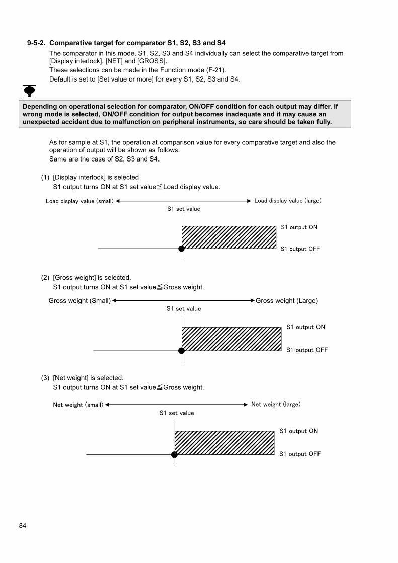
84
9-5-2. Comparative target for comparator S1, S2, S3 and S4
The comparator in this mode, S1, S2, S3 and S4 individually can select the comparative target from [Display interlock], [NET] and [GROSS].
These selections can be made in the Function mode (F-21).
Default is set to [Set value or more] for every S1, S2, S3 and S4.
Depending on operational selection for comparator, ON/OFF condition for each output may differ. If wrong mode is selected, ON/OFF condition for output becomes inadequate and it may cause an unexpected accident due to malfunction on peripheral instruments, so care should be taken fully.
As for sample at S1, the operation at comparison value for every comparative target and also the operation of output will be shown as follows:
Same are the case of S2, S3 and S4.
(1) [Display interlock] is selected
S1 output turns ON at S1 set value≦Load display value.
(2) [Gross weight] is selected.
S1 output turns ON at S1 set value≦Gross weight.
(3) [Net weight] is selected.
S1 output turns ON at S1 set value≦Gross weight.
Load display value (large) Load display value (small)
S1 output ON
S1 output OFF
S1 set value
Net weight (large) Net weight (small)
S1 output ON
S1 output OFF
S1 set value
Net weight (large) Net weight (small)
S1 output ON
S1 output OFF
S1 set value Gross weight (Large) Gross weight (Small)
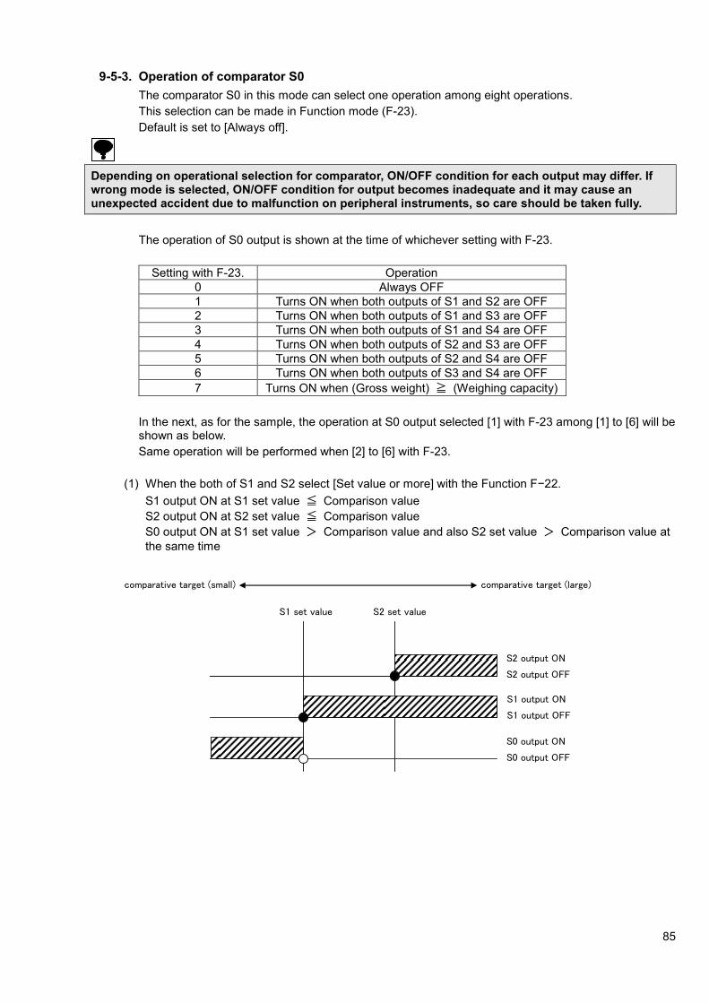
85
9-5-3. Operation of comparator S0
The comparator S0 in this mode can select one operation among eight operations.
This selection can be made in Function mode (F-23).
Default is set to [Always off].
Depending on operational selection for comparator, ON/OFF condition for each output may differ. If wrong mode is selected, ON/OFF condition for output becomes inadequate and it may cause an unexpected accident due to malfunction on peripheral instruments, so care should be taken fully.
The operation of S0 output is shown at the time of whichever setting with F-23.
Setting with F-23. Operation
0 Always OFF
1 Turns ON when both outputs of S1 and S2 are OFF
2 Turns ON when both outputs of S1 and S3 are OFF
3 Turns ON when both outputs of S1 and S4 are OFF
4 Turns ON when both outputs of S2 and S3 are OFF
5 Turns ON when both outputs of S2 and S4 are OFF
6 Turns ON when both outputs of S3 and S4 are OFF
7 Turns ON when (Gross weight) ≧ (Weighing capacity)
In the next, as for the sample, the operation at S0 output selected [1] with F-23 among [1] to [6] will be shown as below.
Same operation will be performed when [2] to [6] with F-23.
(1) When the both of S1 and S2 select [Set value or more] with the Function F−22.
S1 output ON at S1 set value ≦ Comparison value
S2 output ON at S2 set value ≦ Comparison value
S0 output ON at S1 set value > Comparison value and also S2 set value > Comparison value at
the same time
S1 set value S2 set value
comparative target (small) comparative target (large)
S1 output ON
S1 output OFF
S2 output ON
S2 output OFF
S0 output ON
S0 output OFF
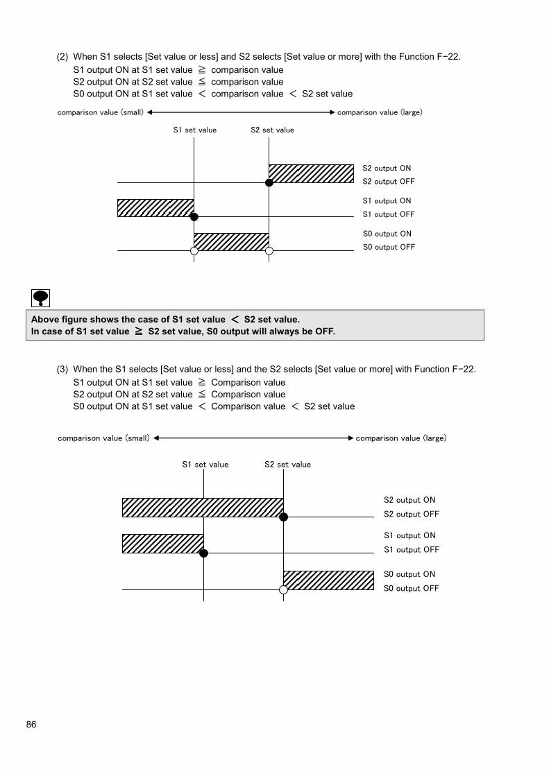
86
(2) When S1 selects [Set value or less] and S2 selects [Set value or more] with the Function F−22.
S1 output ON at S1 set value ≧ comparison value
S2 output ON at S2 set value ≦ comparison value
S0 output ON at S1 set value < comparison value < S2 set value
Above figure shows the case of S1 set value <<<< S2 set value.
In case of S1 set value ≧≧≧≧ S2 set value, S0 output will always be OFF.
(3) When the S1 selects [Set value or less] and the S2 selects [Set value or more] with Function F−22.
S1 output ON at S1 set value ≧ Comparison value
S2 output ON at S2 set value ≦ Comparison value
S0 output ON at S1 set value < Comparison value < S2 set value
comparison value (small) comparison value (large)
S1 set value S2 set value
S2 output ON
S2 output OFF
S1 output ON
S1 output OFF
S0 output ON
S0 output OFF
comparison value (small) comparison value (large)
S1 set value S2 set value
S2 output ON
S2 output OFF
S1 output ON
S1 output OFF
S0 output ON
S0 output OFF

87
9-5-4. Hysteresis on comparator
The comparator S1, S2, S3 and S4 in the instrument can set hysteresis for prevention from chattering at output relay.
Hysteresis can be used by the combined of data width and time width. Moreover, effective direction for hysteresis can be selected from either [OFF delay] or [ON delay].
These selections can be made in Function mode. (Related are F-24, F-25 and F-26). Default is set to hysteresis [OFF].
Depending on the setting of comparator hysteresis, ON/OFF condition for each output way differ. It wrong mode is selected, ON/OFF condition for each output become inadequate and it may cause an unexpected accident due to malfunction on peripheral instruments, so care should be taken fully.
As for the example of S1, the operation of judgment display section when the hysteresis on
comparator is set, will be shown as follows:
The same operation will be obtained in the case of [Normal mode] at S2, S3, S4 and S0.
(1) When the operation of [Set value or more] is selected at S1 and also effective direction for hysteresis is set as [On delay].
(2) When operation of [Set value or more] is selected and [OFF delay] is selected for hysteresis effective width with S1.
Dis
play
Time→
S1 output ON
S1 output OFF
Hysteresis time width
Hysteresis data width
S1 setting value
Dis
play
Time→
S1 output ON
S1 output OFF
Hysteresis data eidth
Hysteresisi time width
S1 set value
Hysterisis time width

88
(3) When operation of [Set value or more] is selected [ON delay] is selected for hysteresis direction, with S1.
(4) When operation of [Set value or less] is selected and [OFF delay] is selected for hysteresis direction with S1.
Dis
play
Time→
S1 output ON
S1 output OFF
Hysteresis time witdh
Hysteresis data width
S1 setting value
Dis
play
Time→
S1 output ON
S1 output OFF
Hysteresis time width
Hysteresis data width
S1 setting value

89
9-6. 4 steps comparator mode 2
In the measurement of the 4 steps comparator node, the comparison results from S0 to S4 is output when the measuring value is in the range of 2 set value after comparing the measuring value with from comparison values or less.
Please set SQ function, SQF-01 to [3] to use this mode.
The setting value of each brand number of 4-steps comparator mode can be set by switching F-20: Comparator brand setting target. (Targeted function is from F21 to F26.)
・ Depending on operational selection for comparator, ON/OFF condition for each output may differ. If
wrong mode is selected, ON/OFF condition for output becomes inadequate and it may cause an unexpected accident due to malfunction on peripheral instruments, so care should be taken fully.
・ The set point of S1, S2, S3, and S4 becomes common with four steps comparator modes 1 and four steps comparator modes 2.
・ Renewing the output of each comparator is synchronizing with A/D sampling.
9-6-1. Comparative target for comparator S1, S2, S3 and S4
The comparator in the instrument, S1, S2, S3 and S4 individually can select the comparative target from [Display interlock], [Net weight] and [Gross weight]; these selections can be made in Function mode. (Function F-21)
Default is set to [Display interlock] is selected for every S1, S2, S3 and S4.
9-6-2. Operation on comparator S1, S2, S3 and S4
In this mode, each operation of comparator S0, S1, S2, S3, and S4 is shown at the follows:
S1 output is ON in the condition that the comparison object value is smaller than S1 set value.
S2 output is ON in the condition of the S1 set point ≦ Comparison object value < S2 set point.
S0 output is ON in the condition of the S2 set point ≦ Comparison object value < S3 set point.
S3 output is ON in the condition of the S3 set point ≦ Comparison object value < S4 set point.
S4 output is ON in the condition of the S4 set point ≦ Comparison object value.
S3 output ON
S3 outputOFF
comparison value (small) comparison value (large)
S1 set value S2 set value S3 set value S4 set value
S4 output ON
S4 output OFF
S0 output ON
S0 output OFF
S2 output ON
S2 output OFF
S1 output ON
S1 output OFF

90
9-6-3. Hysteresis on comparator
The comparator S1, S2, S3 and S4 in the instrument can set hysteresis for prevention from chattering at output relay.
Hysteresis can be used by the combined of data width and time width. Moreover, effective direction for hysteresis can be selected from either [OFF delay] or [ON delay].
These selections can be made in Function mode. (Related are F-24, F-25 and F-26). Default is set to hysteresis [OFF].
Depending on the setting of comparator hysteresis, ON/OFF condition for each output way differ. It wrong mode is selected, ON/OFF condition for each output become inadequate and it may cause an unexpected accident due to malfunction on peripheral instruments, so care should be taken fully.
As for the example of S1, the operation of judgment display section when the hysteresis on
comparator is set, will be shown as follows:
(1) When the operation of effective direction for hysteresis is set as [On delay]
S1 output ON
S1 output OFF
Hysteresis data width
S2 setting value
Hysteresis time width
S2 output ON
S2 output OFF
S0 output ON
S0 output OFF
Dis
pla
y→
Time→
S1 setting value
Hysteresis data width

91
(2) When the operation of effective direction for hysteresis is set as [Off delay]
Hysteresis time width
S2 setting value
Hysteresis data width
Hysteresis data width
S1 setting value
Dis
pla
y→
Time→ S0 output ON
S0 output OFF
S2 output ON
S2 output OFF
S1 output ON
S1 output OFF

92
9-7. SQ function mode
The setting of SQ function data makes various functions related to the sequence operation effective.
9-8. Setting method of the SQ function mode
Change from the standard measurement mode to the
display by the key.
Pressing the key, it displays and enters the mode of SQ function.
By pressing the key, is displayed. Please select SQ function number which you want to change
: The value of changed digit is changed.
: Changed digit is selected.
: The displayed value is changed to [0].
: Display returns to .
: The display value is memorized, and it proceeds to the next step.
: The SQ function mode is finished without changing all setting.
Please press the key, and set the setting value of the selected unction number.
Please press the key. The setting content is registered, and the display panel displays the following registered SQ function number. Please continue and select the selected SQ function number when you change setting of other SQ function numbers.
If the key is pressed after registration is completed, it becomes
display. Please set to the measurement mode by
pressing the key.
Please do not change in the set value under the measurement because the A/D sampling rate decreases temporarily while rewriting the set value.
Measurement mode
Completing registration.
Measurement mode

93
9-9. Function of SQ function data Item Function No. Setting value Contents
Weighing mode SQF-01 0 Simple comparison mode
●1 Sequential mode
2 4 steps comparator mode 1
3 4 steps comparator mode 2
Control mode SQF-02 ●0 Batch mode
1 Discharge mode
2 External input changeover
Comparison signal operation
SQF-05 0 Anytime
1 In stable condition
●2 Synchronizing with batch finish
3 HOLD at synchronizing with batch finish
Near zero comparison operation
SQF-06 ●0 Gross
1 Net
2 OFF
3 |Gross|
4 |Net|
Full comparative operation SQF-07 ●0 Gross
1 Net
2 OFF
3 |Gross|
4 |Net|
Batch Monitoring Timer SQF-10 0000 ~ 9999
●0000
Unit:1s
0000:Batch Monitoring Timer OFF
Start above near zero at the time of batch start
SQF-15 ●0 Invalid
1 Effective
Automatic tare at the time of batch start
SQF-16 ●0 Invalid
1 Effective
Batch start delay timer SQF-17 0000 ~ 9999
●0000
Unit:1s
0000:Batch start delay timer OFF
Automatic tare after batch start delay timer
SQF-18 ●0 Invalid
1 Effective
F-flow compare stop timer SQF-20 0000 ~ 9999
●0000
Unit:0.01s
0000:F-flow compare stop timer OFF
M-flow compare stop timer SQF-21 0000 ~ 9999
●0000
Unit:0.01s
0000:M-flow compare stop timer OFF
D-flow compare stop timer SQF-22 0000 ~ 9999
●0000
Unit:0.01s
0000:D-flow compare stop timer OFF
Flow/Discharge brand setting target
SQF-24 ●0 Brand No. 0
1 Brand No. 1
2 Brand No. 2
3 Brand No. 3
4 Brand No. 4
5 Brand No. 5
6 Brand No. 6
7 Brand No. 7
Automatic free fall compensation
SQF-25 ●0 Invalid
1 Effective
Width for the automatic free fall compensation
SQF-26 00000 ~ 99999
●00000
Unit:1D
00000:Automatic free fall compensation
OFF
Save of automatic free fall value
SQF-27 ●0 Invalid
1 Effective
●Has been set as default

94
Item Function No. Setting value Contents
Judge condition SQF-30 ●0 Timer is up
1 Stable and timer is up
2 Stable or timer is up
Waiting time for judge SQF-31 0000 ~ 9999
●0000
Unit:0.01s
0000:Waiting time for judge OFF
Maximum time of compensation flow
SQF-35 000to255
●000
Unit:1time
000:compensation flow OFF
Judge condition after compensation flow
SQF-36 ●0 Timer is up
1 Stable and timer is up
2 Stable or timer is up
Compensation flow time SQF-37 0000 ~ 9999
●0000
Unit:0.01s
0000:Compensation flow OFF
Waiting time for judge after compensation flow
SQF-38 0000 ~ 9999
●0000
Unit:0.01s
0000: Waiting time for judge after
compensation flow OFF
Output time for the Batch finish signal
SQF-40 0000 ~ 9999
●0000
Unit:0.01s
0000: Output time for the Batch finish
signal OFF
Batch finish output OFF SQF-41 ●0 No condition
1 OL or unstable
2 Near zero
Discharge start at the time batch finish
SQF-45 ●0 Invalid
1 Effective
Discharge monitor timer SQF-46 0000 ~ 9999
●0000
Unit:1s
0000:Discharge monitor OFF
Discharge gate close delay time
SQF-47 0000 ~ 9999
●0000
Unit:0.01s
0000: Discharge gate close delay time
OFF
Discharge finish output time
SQF-48 0000 ~ 9999
●0000
Unit:0.01s
0000:Discharge finish output OFF
Tare cancellation at the time of discharge finish
SQF-49 ●0 Invalid
1 Effective
All brand accumulation clear
SQF-98 Clear accumulation times and accumulation value for all brands
Memory clear SQF-99 Set the SQ function content is returned to setting default
●Has been set as default

95
10. Various functions by SQ function data 10-1. Weighing mode
The measurement mode can be selected by the setting of SQ function SQF-01.
The measurement mode can be selected from the [Simple comparison mode], [Sequential mode], [4-steps comparator mode 1] or [4-steps comparator mode 2].
Default is set to [Sequential mode].
10-2. Control mode
The control mode can be selected by the setting of SQ function SQF-02.
The control mode can be selected from the [Batch mode], [Discharge mode] or [External input changeover].
When the [External control changeover] is selected, [Batch mode] is selected when the [BATCH/DISCHARGE changeover] signal of setting method of the external control input is ON, and [Discharge mode] is selected when the [BATCH/DISCHARGE changeover] signal of setting method of the external control input is OFF.
Default is set to [Batch mode]
10-3. Comparison signal operation
The operation condition of the comparison signal can be selected by SQ function SQF-05.
The operation condition of the comparison signal can be selected from [Anytime], [In stable condition], [Synchronizing with batch finish] or [HOLD at synchronizing with batch finish].
Default is set to [Synchronizing with batch finish].
10-4. Near zero (ZERO BAND) comparison operation
The operation condition of near zero signal can be selected by SQ function SQF-06.
The operation condition of near zero signals can be selected from [GROSS], [NET], [Comparison signal OFF] or [| GROSS | and | NET |].
Default is set to [GROSS].
10-5. Full comparative operation
The operation condition of [FULL] signal can be selected by SQ function SQF-07.
The operation condition of [FULL] signal can be selected from [GROSS], [NET], [Comparison signal OFF] or [| GROSS | and | NET |].
Default is set to [GROSS].
10-6. Batch Monitoring Timer
Set the timer that monitors the time from the input of Start signal to the output of Finish signal by
SQ function SQF-10
When the measuring time is longer than the set value, the error is output.
The contents of error are as follows: When the [CONTROL MODE] is selecting [BATCH MODE], [SQERR 4] can be seen and the [EXTERNAL] is selected, [SQERR 5] can be seen.
Setting range: 0000-9999, Unit: 1s, 0000: OFF
Default is set to [0000]

96
10-7. Setting for operation at the time batch start
10-7-1. Start above near zero at the time of batch start
The operation when input batch start signal with measurement value is exceeded [ZERO BAND] is selected by SQ function SQF-15.
When the [Start above near zero at the time of batch start] is set as [Invalid], measurement value is exceeded [Near zero], batching will not be made due to the occurrence of error with the input of batch.
Default is set to [Invalid].
10-7-2. Automatic tare at the time of batch start
The operation of Automatic tare at the time of batch start is selected by SQ function SQF-16.
Default is set to [Invalid].
10-7-3. Batch start delay timer
Set the waiting time from the input of Batch start signal to the start of Batch at SQ function SQF-17
Setting range: 0000-9999, Unit: 1s, 0000: OFF
Default is set to [0000]
10-7-4. Automatic tare after batch start delay timer
The operation of Automatic tare after batch start delay timer is selected by SQ function SQF-18.
Default is set to [Invalid].
10-8. F-flow compare stop timer
Set the inhibiting time to compare the set value of F-FLOW and measured value at the time of start of Batching.
Setting range: 0000-9999, Unit: 0.01s, 0000: OFF
Default is set to [0000].
10-9. M-flow compare stop timer
Set the inhibiting time to compare the set value of M-FLOW and measured value at the time of finishing the F-FLOW.
Setting range: 0000-9999, Unit: 0.01s, 0000: OFF
Default is set to [0000].
10-10. D-flow compare stop timer
Set the inhibiting time to compare the set value of D-FLOW and measured value at the time of finishing the M-FLOW.
Setting range: 0000-9999, Unit: 0.01s, 0000: OFF
Default is set to [0000].

97
10-11. Flow/Discharge brand setting target
The flow/discharge brand setting target is set by SQ function SQF-24.
SQF-26: Width for the automatic free fall compensation, SQF-37: Compensation flow time, and SQF-38: Waiting time for judge after compensation flow can be set for each brand number selected as the flow/discharge brand setting target.
SQF-24: Flow/Discharge brand setting target setting is not stored in EEPROM. Returns to default when the power is turned off and back on again.
Setting range: 0 to 7
Default is set to [0].
10-12. Automatic free fall compensation
This is a function to guess the next Free Fall from a former actual Free Fall, and to set the value of the Free Fall automatically when the measurement is operated continuously.
Set data of the next Free Fall uses the moving averaged value calculated from 4 times of actual former Free Fall values.
10-12-1. Setting of automatic free fall compensation
The operation of Automatic free fall compensation is selected by SQ function SQF-25.
Default is set to [Invalid].
10-12-2. Width for the automatic free fall compensation
The width for the automatic free fall compensation is set by SQ function SQF-26.
The width for the automatic free fall compensation can be set for each brand number by setting SQF-24: Flow/Discharge brand setting target.
Setting range: 00000 to 99999, Unit: 1D, 00000: OFF
Default is set to [00000].
10-12-3. Save of automatic free fall value
The operation of save of automatic free fall value is selected by SQ function SQF-27.
When save of automatic free fall value is set as [VALID], the value compensated by automatic free fall compensation is saved setting value of free fall (SET2).
Default is set to [Invalid].
10-13. Judge condition
Judge condition at the time of finishing measuring is selected by SQ function SQF-30.
Judge condition at the time of finishing measuring is selected from [Timer is up], [Stable and timer is up] or [Stable or timer is up].
Default is set to [Timer is up].
10-14. Waiting time for judge
Set the waiting time until executing judgment after D-FLOW is finished by SQ function SQF-31
Setting range: 0000-9999, Unit: 0.01s, 0000: OFF
Default is set to [0000].

98
10-15. Setting for the operation of compensation flow
Set for the operation of compensation flow.
10-15-1. Maximum time of compensation flow
Set the maximum time of compensation flow by SQ function SQF-35.
Setting range: 000-255, Unit: 1time, 000:OFF
Default is set to [000].
10-15-2. Judge condition after compensation flow
Judge condition after compensation flow can be selected by SQ function SQF-36.
Judge condition after compensation flow can be selected from [Timer is up], [Stable and timer is up] or [Stable or timer is up].
Default is set to [Timer is up].
10-15-3. Compensation flow time
The compensation flow time is set by SQ function SQF-37.
The compensation flow time can be set for each brand number by setting SQF-24: Flow/Discharge brand setting target.
Setting range: 0000 to 9999, Unit: 0.01s, 0000: Compensation flow OFF
Default is set to [0000].
10-15-4. Waiting time for judge after compensation flow
The waiting time for judge after compensation flow is set by SQ function SQF-38.
The waiting time for judge after compensation flow can be set for each brand number by setting SQF-24: Flow/Discharge brand setting target.
Setting range: 0000 to 9999, Unit: 0.01s, 0000: Compensation flow OFF
Default is set to [0000].
10-16. Setting for the operation of measuring finish output
Set for the operation of measuring finish output
10-16-1. Output time for the Batch finish signal
Set the output time for the Batch finish signal by SQ function SQF-40.
Setting range: 0000-9999, Unit: 0.01s, 0000: OFF
Default is set to [0000].

99
10-16-2. Batch finish output OFF
The condition to make OFF the output of completion of batch can be selected by SQ function SQF-41.
The condition to make OFF the output of completion of batch can be selected from [No condition], [OL or unstable] and [Near zero].
When the [No condition] is selected, the FINISH signal will be OFF whether the set time with the [BATCH FINISH OUTPUT IN] has passed, or next start signal is inputted.
When the [OL or unstable] is selected, the FINISH signal will be OFF whether the display becomes OL or – OL, or output of Stable signal will become OFF.
When the [Near zero] is selected, the FINISH signal will be OFF at the time of Near zero signals is outputted.
Default is set to [NO CONDITION].
10-17. Setting for discharge operation after measuring finish
Set for discharge operation after measuring finish.
10-17-1. Discharge start at the time of measuring finish
Set the operation of discharge start at the time of measuring finish by SQ function SQF-45.
Default is set to [Invalid].
10-17-2. Discharge monitor timer
Set the timer that monitors the time from the Discharge start to Discharge finish by SQ function SQF-46.
Setting range: 0000-9999, Unit: 1s, 0000: OFF
Default is set to [0000].
10-17-3. Discharge gate close delay time
When measurement value fills near zero condition during discharge is executing then set the time
up to gate closing by SQ function SQF-47.
Set the timer that monitors the time from the Discharge start to Discharge finish by SQ function SQF-46.
Setting range: 0000-9999, Unit: 0.01s, 0000: OFF
Default is set to [0000].
10-17-4. Discharge finish output time
Set the output time for the discharge finish signal by SQ function SQF-48.
Setting range: 0000-9999, Unit: 0.01s, 0000: OFF
Default is set to [0000].
10-17-5. Tare cancellation at the time of discharge finish
Set the operation of tare cancellation at the time of discharge finish by SQ function SQF-49.
Default is set to [Invalid].
100
10-18. Accumulation clear
Accumulation clear is executed by SQ function SQF-98.
Clear the accumulation times and the accumulation value.
If the key is pressed when displays, becomes blinking.
At this time, please press the key to discontinue a clear memory.
It becomes a stand-by mode, and a clear memory is not executed.
When is a blinking display, the display section is turned off by pressing the key,
and it becomes display, the operation of memory clear is completed.
10-19. SQ function clear
SQ function clear is executed by SQ function F-99.
The setting content of the SQ function is returned to the default setting.
When the key is pressed with displayed, becomes a blinking display.
At this time, please press the key to discontinue a clear memory.
It becomes a stand-by mode, and a clear memory is not executed.
When is a blinking display, the display section is turned off by pressing the key,
and it becomes display, the operation of memory clear is completed.
Please do not clear the SQ function under the measurement to cause an unexpected malfunction.

101
11. Stored place of setting data In this unit, each data is recorded in RAM and EEPROM as follows:
The data in EEPROM can be stored almost permanent due to nonvolatile.
Moreover, RAM is backed up with the battery. (The backup time is about ten years in the room temperature.)
11-1. Data recorded in RAM
● Tare weight cancellation data ● Preset tare weight cancellation data
● Zero tracking data ● Accumulated value, Accumulated count data
● Zero set data
11-2. Data recorded in EEPROM
● Calibration data ● SQ function data
● Function data ● Digital linearize data
● C function data
11-3. Data can be changed saving location
The saving location of follow data’s, is selected by C function CF-17
The saving location is selected from [RAM] or [EEPROM].
The item to which the saving location can be changed is as follows.
[RAM] is set as a default.
● Measurement comparison value 1 setting data
● Measurement comparison value 2 setting data
・ Please set the stored place to the internal RAM when the set value is continuously changed, and the
rewritable time of EEPROM might exceed about one million times.
・ Please do not change in the set value under the measurement because the A/D sampling rate decreases temporarily while rewriting the set value. Please set the storing place to the internal ROM when you change the set value during the measurement.

102
12. Check mode In the check mode, the following confirmations can be made.
● EzCTS mode ● ROM version ● Confirmation of options
● External control input operation ● External control output operation
● Output voltage of the load cell ● BCD output operation (Option)
● Analog output (Option)

103
12-1. Setting method of Check mode
By pressing the key from the normal measurement mode, it enters into the stand-by condition.
When the key is pressed with pressing the key,
is displayed.
When the key is pressed after pressing the key.
The display becomes , and enters into the check mode. In the check mode, if it is either of display section as the following, the confirmation item can be switched by the
operation of the key or the key.
: Changeover of the check mode item
: Quit from the check mode
Measurement mode
+
12-3. Confirmation of ROM version
12-6. Confirmation of external control output
12-7. Confirmation of load cell output voltage
12-8. Confirmation of BCD output
(When BCD output is applied.)
12-9. Confirmation of analog output
(When the analog output is applied.)
12-4. Confirmation of options
12-5. Confirmation of external control input
12-2. Confirmation of EzCTS mode
Check mode

104
12-2. EzCTS mode
When the key is pressed from display,
display changes into the blinking display.
And it becomes possible to use EzCTS while the display is blinking.
EzCTS in communication with the personal computer it can precede reading-out and writing the function data.
At this time, the RS-485 interface equipped as a standard becomes effective.
Process reading-out and writing the set data by PC in which the optional software of EzCTS is installed in this mode.
・ In EzCTS mode, do not connect with other than EzCTS to standard RS-485 line.
・ In EzCTS mode, the command not used by EzCTS is not returned from CSD-903.
・ In EzCTS mode, except of EzCTS communication does not operate.
12-3. Confirmation of ROM version
When the key is pressed from display, ROM version is blinking displayed.
Move to the Confirmation of options
Move to the Confirmation of
ROM version
EzCTS is the application for personal computer.
It can precede reading-out and writing the function data of CSD-903 easily.
It is useful for maintenance and the backup of data.

105
12-4. Confirmation of options
When the key is pressed from display, equipped option is blinking displayed.
display Combination of optional products
P-- Not output
P07 Current output
P25 Voltage output
P15 BCD output
P73 CC-LINK interface
P74 RS-232C interface
P76 RS-422/485 interface
12-5. Confirmation of external control input
When the key is pressed from display,
display becomes blinking. At this time, the status of ON/OFF of the external control input signal can be confirmed by the status display section. The status display lights when each input of the external control input connector is turned on.
Pin No. Condition
INPUT1 STABLE
INPUT2 PRESET TARE
INPUT3 TARE
INPUT4 GROSS
INPUT5 NET
INPUT6 ZERO
INPUT7 HOLD
INPUT8 ERROR
INPUT9 Z-BAND
Move to the Confirmation of external control input
Confirms by external input ON/OFF.
move to the confirmation of contact output.

106
12-6. Confirmation of external control output
By pressing key with display, OUTPUT1 of
external control output is output after display blinks and [Stable mark] lights.
The position when the lighting [▼] mark is displayed moves when
the key and key is operated at this moment, and the external control output that respond to the position of the mark is turned on.
: Changeover the each contact output
: Quit from the check mode
Condition Pin No.
STABLE OUTPUT1
PRESET TARE OUTPUT2
TARE OUTPUT3
GROSS OUTPUT4
NET OUTPUT5
ZERO OUTPUT6
HOLD OUTPUT7
ERROR OUTPUT8
Z-BAND OUTPUT9
F.FLOW/S1 OUTPUT10
M.FLOW/S2 OUTPUT11
D.FLOW/S3 OUTPUT12
OVER/S4 OUTPUT13
Move to the Confirmation of load cell output voltage
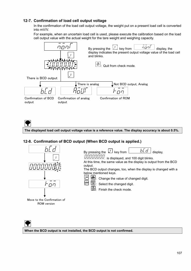
107
12-7. Confirmation of load cell output voltage
In the confirmation of the load cell output voltage, the weight put on a present load cell is converted into mV/V.
For example, when an uncertain load cell is used, please execute the calibration based on the load cell output value with the actual weight for the tare weight and weighing capacity.
By pressing the key from display, the display indicates the present output voltage value of the load cell and blinks.
: Quit from check mode.
The displayed load cell output voltage value is a reference value. The display accuracy is about 0.5%.
12-8. Confirmation of BCD output (When BCD output is applied.)
By pressing the key from display,
is displayed, and 100 digit blinks. At this time, the same value as the display is output from the BCD output. The BCD output changes, too, when the display is changed with a below mentioned keys.
: Change the value of changed digit.
: Select the changed digit.
: Finish the check mode.
When the BCD output is not installed, the BCD output is not confirmed.
There is BCD output
Move to the Confirmation of ROM version
Confirmation of BCD output
Confirmation of analog output
There is analog output
Confirmation of ROM version
Not BCD output, Analog output なし

108
12-9. Confirmation of analog output (When the analog output is applied.)
By pressing the key from
display, is displayed, and the analog output of DC4 mA(DC0 V) is made. At this time, when the under mentioned key is operated, the analog output of DC 12 mA (DC5 V) is output in
display, and the analog output of DC
DC20 mA (DC10 V) is output in display.
: Changeover each analog output.
: Finish the check mode.
When the analog output is not installed, the confirmation of analog output is not executed.

109
13. 2 wire serial interface(S-I/F) 13-1. Interface specification
Specifications Contents
Baud rate 600 bps
Data length 8 bit
Parity bit ODD
Stop bit 1 bit
Start bit 1 bit
Sending date Binary code, BCD
13-2. Data format
(1) INTERVAL Space for 15 bit(25 ms) or more (MARK SIGNAL)
(2) F1~F3 0FFH code
(3) LEN 11H code (4) FUN1 Printing status (5) FUN2 00H code (6) ST1 Condition (7) ST2 Condition (8) OVR 00H code (9) ERR Condition
(10) G1~G3 GROSS data
(11) N1~N3 NET data
(12) T1~T3 TARE data
(13) BCC Block Checking Character from LEN to T3
(1) FUN1
7 6 5 4 3 2 1 0
(2) ST1
7 6 5 4 3 2 1 0
(3) ST2
7 6 5 4 3 2 1 0
(4) GROSS data/NET data/TARE data
G1/ N1/ T1 G2/ N2/ T2 G3/ N3 /T3
DP 104 103 102 101 100
76 Decimal point
00 Nothing
01 101
10 102
11 103
1 2 3 4 5 6 7 8 9 10 11 12 13 14 15 16 17 18 19 20
INTERVAL F1 F2 F3 LEN FUN1 FUN2 ST1 ST2 OVR ERR G1 G2 G3 N1 N2 N3 T1 T2 T3 BCC
Printing status
On [1] means NET display
On [1] means GROSS display
On [1] means preset tare is valid
Load data・BCD data・TARE data
7 6 4 5
On [1] means minus
sign Decimal point

110
・ Only during the measurement mode, the output of serial data is done.
・ The output of the data of S-I/F stops when the maximum display is set to six digits. Set the maximum display within five digits when you use S-I/F.
・ The output of the data of S-I/F stops when decimal point is from digits. Set the decimal point less than three digits when you use S-I/F
・ Make connection by referring to the 2-4.
13-3. Format data explanation
(1) Automatic print bit (FUN1: bit 0)
This bit can be used as a trigger at the instrument of serial interface receiving side.
(2) Display bit (ST1:bit 7、bit 6)
Bit 7: When the display of the instrument is gross weight, set as [1].
Bit 6: When the display of the instrument is net weight, set as [1].
13-4. Explanation of output type
(1) Stream mode
Keep outputting the data of gross weight and the net weight in constant intervals.
(2) Print signal operation
Print signal operation is selected by function F-37 and can be selected from [OFF], [Synchronizing with print signal], [Synchronizing with accumulation signal], and [Synchronizing with finish signal].
When [Synchronizing with print signal] is selected, send with [1] set to the automatic print bit on the
FUN1 of output format synchronized with the key, the external control input, or automatic printing.
When [Synchronizing with accumulation signal] is selected, send with [1] set to the automatic print bit on the FUN1 of output format when [Accumulation command] is input by the function F-50 setting,
key, or external control input.
When [Synchronizing with finish signal] is selected, send with [1] set to the automatic print bit on the
FUN1 of output format when [Forced batch finish] is input by the key or external control input or synchronized with the batch finish signal.
Default is set to [OFF].
The automatic print bit is usually 0.

111
14. Standard RS-485 Communication 14-1. Specifications for standard RS-485 communication
Specification Content
Transmission method Half duplex
Synchro system Start-stop synchronization
Baud rate Select from 1 200 bps, 2 400 bps, 4 800 bps, 9 600 bps, 19 200 bps and 38 400 bps.
Data bit length Select from 7 bit and 8 bit.
Parity bit Select from No parity, even parity or odd parity.
Stop bit Select from 1 bit or 2 bit.
Terminator Select from CR+LF or CR
Transmission data ASCII code
Length of cable About 1 km
Address One is selected among 0 to 31.
The number of connection 32 at maximum.
The standard RS-485 communication and Modbus communication, and optional RS-232C communication, and RS-422 communication, and RS-485 communications are not interlocked each other.
14-2. Data format
As for the data format, refer to [6-3-12. Command mode data format].
14-3. Item of standard RS-485 communication setting
14-3-1. Operation mode
The operation mode for standard RS-485 communication is selected by setting function F-47. The operation mode can be selected from [Command mode], [Stream mode], [Synchronizing with finish], [Synchronizing with accumulation signal], [Synchronizing with print signal], and [Modbus].
Default is set to [Command mode]. See "15. Modbus communication" for details of Modbus communication.
(1) Command mode
Data is sent back from CSD-903 to the host side according to the command/data sent to CSD-903 and provided by the host (personal computer or sequencer, etc.).
(2) Stream mode
When RS-485 is used, it keeps outputting the latest data of the output target selected by function F-47.
Note that the output frequency changes depending on the baud rate setting.
(3) Synchronizing with print signal
Data is output synchronized with the print signal (F key, external control input, or automatic print).
(4) Synchronizing with accumulation signal
Data is output when [Accumulation command] is input by the function F-50 setting, key, or external control input.

112
(5) Synchronizing with finish signal
Data is output when [Forced batch finish] is input by F key or external control input or synchronized with the batch finish signal.
RS-485 interface keeps outputting data at the fixed space when the stream mode is selected. Moreover, the control becomes impossible for the host.
14-3-2. Specifications of communication by RS-485
The specification of the communication by RS-485 is selected by function F-42.
Function No. Set value Contents
F-42 00000
~13121 0 0 0 0 0
Data bit length 0:7 bit or 1:8 bit
Parity bit 0:No parity
1:Even parity
2:Odd parity
Stop bit 0:1 bit or 1:2 bit
Baud rate 0 : 1 200 bps, 1 : 2 400 bps
2 : 4 800 bps, 3 : 9 600 bps 4 : 19 200 bps, 5 : 38 400 bps
Terminator 0 : CR or 1 : CR+LF
Default is set to [13020].
14-3-3. Address setting of RS-485
The address setting of RS-422/485 is set by the setting of function F-43.
Setting range: 00 ~ 31
Default is set to [00].
14-3-4. Delay time of RS-485 return data
When the transmitting terminal on the host side enters the state of low impedance after the host side transmission ends, the return data of the CSD-903 side can be delayed.
The delay time of RS-485 return data is set by the function F-45.
Setting range: 00 ~ 99, Unit: 10 ms
Default is set to [01].
14-3-5. Transmission data decimal point existence of RS-485
The transmission data decimal point existence of RS-485 is selected by function F-46.
Default is set to [No decimal point].
14-3-6. Output target at the stream mode in RS-485 interface
Output target is selected by the setting of function F-48.
Output target is selectable from [Display interlock], [Gross value], [Net value] or [Conditional load display data].
Default is set to [Display interlock].
Function F-48 becomes effective when function F-47 is set to [2].

113
14-4. Connecting method
14-4-1. One to one
RS-485+
RS-485-
S.G.
A
B address 00
S.G.
RS-485 host CSD-903
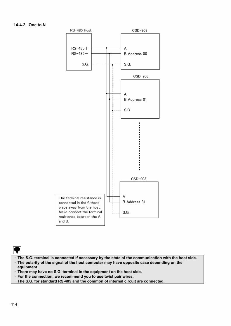
114
14-4-2. One to N
・ The S.G. terminal is connected if necessary by the state of the communication with the host side.
・ The polarity of the signal of the host computer may have opposite case depending on the equipment.
・ There may have no S.G. terminal in the equipment on the host side.
・ For the connection, we recommend you to use twist pair wires.
・ The S.G. for standard RS-485 and the common of internal circuit are connected.
The terminal resistance is connected in the futhest place away from the host. Make connect the terminal resistance between the A and B.
A
B Address 31
S.G.
A
B Address 01
S.G.
CSD-903
CSD-903
RS-485+
RS-485-
S.G.
A
B Address 00
S.G.
RS-485 Host CSD-903

115
15. Modbus communication The Modbus communication is a serial interface used for standard RS-485 communication.
The communication with the instrument supported with the Modbus communication can be done without program.
- Modbus is a registered trademark of the Modicon Inc.
The data communication with CSD-903 does not have to make the program of the communication protocol because it can be operated with the mapped memory operation in the table below.
When using the Modbus communication, set as shown in [14-3.Item of RS-485 communication setting] as below.
Standard RS-485 should be used as hardware of communication.
Moreover, as for decimal point addition, the terminator, and communication delay time, the setting will become in VALID since they have no relation with the Modbus operation.
Item Set value
Operation mode Modbus
Baud rate Make selection from 1 200 bps,2 400 bps,4 800 bps, 9 600 bps, 19 200 bps and 38 400 bps.
Data bit length 8 bit
Parity bit Selection from no parity, even parity, and odd parity
Stop bit Select from 1 bit and 2 bit.
Address Select one from 0 to 31. However, 0 is the broadcast address
・ The standard RS-485 interface and Modbus communication cannot be used when the optional
communication either of RS-232C, RS-422, RS-485 or CC-Link is equipped with Communication and Modbus communication, and optional RS-232C communication, and RS-422 communication, and RS-485 communication, and CC-Link communications are not interlocked each other.
・ Function F-45 shall be applied with more than the value of [01].
・ Please set the delay time of 5 ms or more to host side.
・ To use the brand number in Modbus communication holding register [53249], set function F-51 to [2]. To use the F-52 brand selection settings [57447 to 57448], set function F-51 to [0].
Output coil (Bit, Reading out/Writing, Reference 0)
Address Data name Address Data name 1 ZERO 13 UNUSED 2 ZERO CLEAR 14 EMERGENCY STOP 3 TARE 15 UNUSED 4 TARE CLEAR 16 FORCED BATCH FINISH 5 FLOW START 17 UNUSED 6 UNUSED 18 FORCED DISCHARGE FINISH 7 DISCHARGE START 19 ERROR RESET 8 UNUSED 20 CHANGE OF HOLD/HOLD RELEASE 9 MANUAL FREE FALL COMPENSATION 21 PRINT COMMAND
10 ACCUMULATION COMMAND 22 GROSS/NET CHANGEOVER 11 CLEAR THE LAST ACCUMULATED DATA 23 ALL BRAND ACCUMULATION CLEAR 12 UNUSED 24 UNUSED

116
Input status (bit reading out reference 1) Address Data name Address Data name
17 STABLE 43 DURING TARE 18 NEAR ZERO 44 PRESET TARE 19 FULL 45 CENTER OF ZERO 20 FULL FLOW/S1 46 GROSS DISPLAY 21 MEDIUM FLOW/S2 47 NET DISPLAY 22 DRIBBLE FLOW/S3 48 HOLD 23 OVER/S4 49 BRAND NO. 0 ACCUMULATION ERROR 24 OK/S0 50~304 UNUSED 25 UNDER 305 BRAND NO. 1 ACCUMULATION ERROR
26~28 UNUSED 306~560 UNUSED 29 DISCHARGE 561 BRAND NO. 2 ACCUMULATION ERROR 30 BATCH FINISH 562~816 UNUSED 31 UNUSED 817 BRAND NO. 3 ACCUMULATION ERROR 32 DISCHARGE FINISH 818~1072 UNUSED
33~35 UNUSED 1073 BRAND NO. 4 ACCUMULATION ERROR 36 DURING WEIGHING SEQUENCE 1074~1328 UNUSED 37 UNUSED 1329 BRAND NO. 5 ACCUMULATION ERROR 38 WEIGHING SEQUENCE ERROR 1330~1584 UNUSED 39 ABNORMAL WEIGHT 1585 BRAND NO. 6 ACCUMULATION ERROR 40 ZERO ERROR 1586~1840 UNUSED 41 ERROR 1841 BRAND NO. 7 ACCUMULATION ERROR 42 UNUSED
Input registers (word reading out/writing reference 3)
Address Data name Address Data name 1 DECIMAL POINT 64 STATUS ERROR CODE 2 UNIT 65~98 UNUSED
3~4 TARE WEIGHT 99 SOFTWARE VERSION 5~6 GROSS WEIGHT 100~288 UNUSED 7~8 NET WEIGHT 289 BRAND NO. 1 ACCUMULATION TIMES 9~11 UNUSED 291~294 BRAND NO. 1 ACCUMULATION VALUE
(10 digits) 12 SEQUENCE ERROR NUMBER 295~544 UNUSED 13 ABNORMAL WEIGHT 545~546 BRAND NO. 2 ACCUMULATION TIMES 14
ZERO ERROR 547~550 BRAND NO. 2 ACCUMULATION VALUE
(10 digits) 15 ERROR 551~800 UNUSED 16 UNUSED 801~802 BRAND NO. 3 ACCUMULATION TIMES
33~34 BRAND NO. 0 ACCUMULATION VALUE (8 digits)
803~806 BRAND NO. 3 ACCUMULATION VALUE
(10 digits) 35~36 BRAND NO. 0 ACCUMULATION TIMES 807~1056 UNUSED 37~40 BRAND NO. 0 ACCUMULATION VALUE
(10 digits) 1057~1058
BRAND NO. 4 ACCUMULATION TIMES
41~50 UNUSED 1059~1062
BRAND NO. 4 ACCUMULATION VALUE (10 digits)
51 STATUS 1063~1312 UNUSED 52 STATUS ERROR CODE 1313~1314 BRAND NO. 5 ACCUMULATION TIMES
53~54 TARE WEIGHT 1315~1318
BRAND NO. 5 ACCUMULATION VALUE (10 digits)
55 STATUS 1319~1568 UNUSED 56 STATUS ERROR CODE 1569~1570 BRAND NO. 6 ACCUMULATION TIMES
57~58 GROSS WEIGHT 1571~1574
BRAND NO. 6 ACCUMULATION VALUE (10 digits)
59 STATUS 1575~1824 UNUSED 60 STATUS ERROR CODE 1825~1826 BRAND NO. 7 ACCUMULATION TIMES
61~62 NET WEIGHT 1827~1830
BRAND NO. 7 ACCUMULATION VALUE (10 digits)
63 STATUS

117
(1) Sequence error number
A number is written to input register address 12 when a sequence error occurs.
Number Details Action
1 If forcibly stopped by inputting an emergency stop during weighing
Check the cause of the emergency stop, reset the error, and restart.
3 If insufficient even after compensation flow
Alter the compensation flow time and maximum number of compensation flow times, and restart.
4 If there is a contradiction in the comparison values
Check the settings to eliminate the cause of the contradiction.
5 If the flow time exceeds the time limit Check for flow gate blockage.
6 If the discharge time exceeds the time limit
Check for discharge gate blockage.
7 If the gross value is smaller than the final value in discharge control
Check for flow gate blockage.
8 If the net value is greater than or equal to
the (final value – free fall) at the start
Remove the contents in the container.
10 If measurement begins while START is [Effective] other than for NEAR ZERO, and no container is placed on the measuring section
Check that a container is in place.
(2) Status
Status is written as the bits to input register addresses 51, 55, 59, and 63.
Bit Details
Bit15 STABLE
Bit14 TARE WEIGHT CANCELLATION SETTING
Bit13 TARE WEIGHT CANCELLATION
Bit12 GROSS WEIGHT
Bit11 NET WEIGHT
Bit10 CENTER OF ZERO
Bit9 HOLD
Bit8 ERROR
Bit7 NEAR ZERO
Bit6 FULL FLOW/S1
Bit5 MEDIUM FLOW/S2
Bit4 DRIBBLE FLOW/S3
Bit3 OVER/S4
Bit2 OK/S0
Bit1 UNDER
Bit0 FULL

118
(3) Status error codes
Status error codes are written as numbers to input register addresses 52, 56, 60, and 64.
Number Details
1 If zero setting was performed outside the valid zero setting range
2 If a number not on the list was selected for C function or function setting
4 A/D conversion error
8 If tare weight cancellation was performed outside the tare weight cancellation operation range
10 Lights when the load display exceeds [(-weighing value) - 9D], exceeds [-110% of weighing value], or exceeds [-20D]. (Depending on C function CF-03 setting)
11 Lights when the load display exceeds [(+weighing capacity) + 9D] or exceeds [+110% of weighing capacity]. (Depending on C function CF-03 setting)
12 A/D converter input minus over
13 A/D converter input plus over
20 If the load cell output and numerical input is equal to or under -2.5 mV/V and exceeds the zero adjustment range on the negative side during calibration
21 If the load cell output and numerical input is equal to or over 2.5 mV/V and exceeds the zero adjustment range on the positive side during calibration
22 If the load cell output and numerical input is under 0 mV/V and does not reach the span adjustment range during calibration
23 If the load cell output and numerical input is over 3.1 mV/V and exceeds the span adjustment range during calibration
31 EEPROM writing error
Holding registers (word reading out/writing reference number 4)
Address Data name 1~9 UNUSED
11~12 FINAL/S1 13~14 FREE FALL/S4 15~16 PRIOR TO FIXED VALUE 1/S3 17~18 PRIOR TO FIXED VALUE 2/S2 19~20 OVER 21~22 UNDER 23~24 NEAR ZERO 25~26 FULL 27~28 PRESET TARE WIGHT 29~30 COMPENSATION FLOW TIME 31~32 WAITING TIME FOR JUDGE AFTER COMPENSATION FLOW 33~34 BRAND NO. 1 AUTOMATIC FREE FALL COMPENSATION
35~265 UNUSED 267~268 BRAND NO. 1 FINAL/S1 269~270 BRAND NO. 1 FREE FALL/S4 271~272 BRAND NO. 1 PRIOR TO FIXED VALUE 1/S3 273~274 BRAND NO. 1 PRIOR TO FIXED VALUE 2/S2 275~276 BRAND NO. 1 OVER 277~278 BRAND NO. 1 UNDER 279~280 BRAND NO. 1 NEAR ZERO 281~282 BRAND NO. 1 FULL 283~284 UNUSED 285~286 BRAND NO. 1 COMPENSATION FLOW TIME 287~288 BRAND NO. 1 WAITING TIME FOR JUDGE AFTER COMPENSATION FLOW 289~290 BRAND NO. 1 AUTOMATIC FREE FALL COMPENSATION 291~522 UNUSED 523~524 BRAND NO. 2 FINAL/S1 525~526 BRAND NO. 2 FREE FALL/S4 527~528 BRAND NO. 2 PRIOR TO FIXED VALUE 1/S3 529~530 BRAND NO. 2 PRIOR TO FIXED VALUE 2/S2 531~532 BRAND NO. 2 OVER 533~534 BRAND NO. 2 UNDER 535~536 BRAND NO. 2 NEAR ZERO 537~538 BRAND NO. 2 FULL 539~540 UNUSED 541~542 BRAND NO. 2 COMPENSATION FLOW TIME
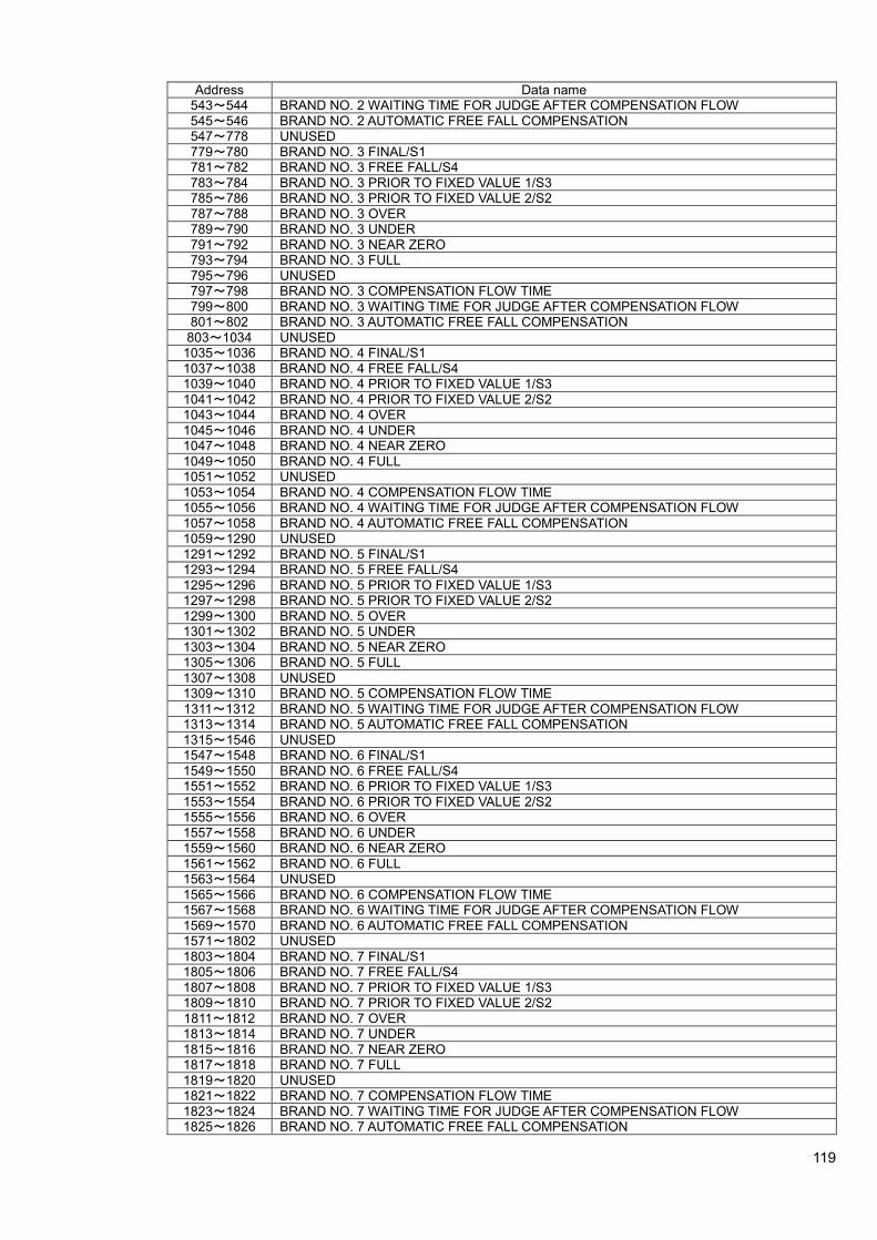
119
Address Data name 543~544 BRAND NO. 2 WAITING TIME FOR JUDGE AFTER COMPENSATION FLOW 545~546 BRAND NO. 2 AUTOMATIC FREE FALL COMPENSATION 547~778 UNUSED 779~780 BRAND NO. 3 FINAL/S1 781~782 BRAND NO. 3 FREE FALL/S4 783~784 BRAND NO. 3 PRIOR TO FIXED VALUE 1/S3 785~786 BRAND NO. 3 PRIOR TO FIXED VALUE 2/S2 787~788 BRAND NO. 3 OVER 789~790 BRAND NO. 3 UNDER 791~792 BRAND NO. 3 NEAR ZERO 793~794 BRAND NO. 3 FULL 795~796 UNUSED 797~798 BRAND NO. 3 COMPENSATION FLOW TIME 799~800 BRAND NO. 3 WAITING TIME FOR JUDGE AFTER COMPENSATION FLOW 801~802 BRAND NO. 3 AUTOMATIC FREE FALL COMPENSATION
803~1034 UNUSED 1035~1036 BRAND NO. 4 FINAL/S1 1037~1038 BRAND NO. 4 FREE FALL/S4 1039~1040 BRAND NO. 4 PRIOR TO FIXED VALUE 1/S3 1041~1042 BRAND NO. 4 PRIOR TO FIXED VALUE 2/S2 1043~1044 BRAND NO. 4 OVER 1045~1046 BRAND NO. 4 UNDER 1047~1048 BRAND NO. 4 NEAR ZERO 1049~1050 BRAND NO. 4 FULL 1051~1052 UNUSED 1053~1054 BRAND NO. 4 COMPENSATION FLOW TIME 1055~1056 BRAND NO. 4 WAITING TIME FOR JUDGE AFTER COMPENSATION FLOW 1057~1058 BRAND NO. 4 AUTOMATIC FREE FALL COMPENSATION 1059~1290 UNUSED 1291~1292 BRAND NO. 5 FINAL/S1 1293~1294 BRAND NO. 5 FREE FALL/S4 1295~1296 BRAND NO. 5 PRIOR TO FIXED VALUE 1/S3 1297~1298 BRAND NO. 5 PRIOR TO FIXED VALUE 2/S2 1299~1300 BRAND NO. 5 OVER 1301~1302 BRAND NO. 5 UNDER 1303~1304 BRAND NO. 5 NEAR ZERO 1305~1306 BRAND NO. 5 FULL 1307~1308 UNUSED 1309~1310 BRAND NO. 5 COMPENSATION FLOW TIME 1311~1312 BRAND NO. 5 WAITING TIME FOR JUDGE AFTER COMPENSATION FLOW 1313~1314 BRAND NO. 5 AUTOMATIC FREE FALL COMPENSATION 1315~1546 UNUSED 1547~1548 BRAND NO. 6 FINAL/S1 1549~1550 BRAND NO. 6 FREE FALL/S4 1551~1552 BRAND NO. 6 PRIOR TO FIXED VALUE 1/S3 1553~1554 BRAND NO. 6 PRIOR TO FIXED VALUE 2/S2 1555~1556 BRAND NO. 6 OVER 1557~1558 BRAND NO. 6 UNDER 1559~1560 BRAND NO. 6 NEAR ZERO 1561~1562 BRAND NO. 6 FULL 1563~1564 UNUSED 1565~1566 BRAND NO. 6 COMPENSATION FLOW TIME 1567~1568 BRAND NO. 6 WAITING TIME FOR JUDGE AFTER COMPENSATION FLOW 1569~1570 BRAND NO. 6 AUTOMATIC FREE FALL COMPENSATION 1571~1802 UNUSED 1803~1804 BRAND NO. 7 FINAL/S1 1805~1806 BRAND NO. 7 FREE FALL/S4 1807~1808 BRAND NO. 7 PRIOR TO FIXED VALUE 1/S3 1809~1810 BRAND NO. 7 PRIOR TO FIXED VALUE 2/S2 1811~1812 BRAND NO. 7 OVER 1813~1814 BRAND NO. 7 UNDER 1815~1816 BRAND NO. 7 NEAR ZERO 1817~1818 BRAND NO. 7 FULL 1819~1820 UNUSED 1821~1822 BRAND NO. 7 COMPENSATION FLOW TIME 1823~1824 BRAND NO. 7 WAITING TIME FOR JUDGE AFTER COMPENSATION FLOW 1825~1826 BRAND NO. 7 AUTOMATIC FREE FALL COMPENSATION

120
Address Data name 1827~53248 UNUSED
53249 BRAND NUMBER 53250~56832 UNUSED
56833 OPERATION MODE 56834 UNUSED
56835~56836 SCALE INTERVAL SETTING 56837~56838 WEIGHING CAPACITY SETTING 56839~56840 WEIGHT MASS SETTING 56841~56842 REGISTER ZERO POINT LOAD CELL OUTPUT VALUE 56843~56844 REGISTER SPAN POINT LOAD CELL OUTPUT VALUE
56845 ACTUAL WEIGHT CALIBRATION STABILITY CONFIRMATION 56846 ACTUAL WEIGHT CALIBRATION REGISTER ZERO POINT 56847 ACTUAL WEIGHT CALIBRATION REGISTER SPAN POINT 56848 CALIBRATION FINISH 56849 ZERO POINT FINE ADJUSTMENT 56850 SPAN POINT FINE ADJUSTMENT
56851~56852 POINT 1 WEIGHT 56853~56854 POINT 2 WEIGHT 56855~56856 POINT 3 WEIGHT 56857~56858 FINE ADJUSTMENT MODE, LOAD DISPLAY 56859~57344 UNUSED 57345~57346 F-01 DIGITAL FILTER SETTING 57347~57348 F-02 ANALOG FILTER SETTING
57349~573450
UNUSED
57351~57352 F-04 DISPLAY TIMES 57353~57354 F-05 STABILIZING FILTER SETTING 57355~57356 F-06 STABILIZING FILTER DATA WIDTH 57357~57358 F-07 STABILIZING FILTER TIME WIDTH 57359~57360 F-08 KEY LOCK 1 57361~57362 F-09 KEY LOCK 2 57363~57364 F-10 STABILITY DETECTION DATA WIDTH 57365~57366 F-11 STABILITY DETECTION TIME WIDTH 57367~57372 UNUSED 57373~57374 F-15 OPERATING CONDITION OF PRESET TARE WEIGHT CANCELLATION 57375~57376 F-16 PRINT OPERATION 57377~57378 F-17 HOLD OPERATION 57379~57380 F-18 HOLD TARGET 57381~57382 F-19 SELECTION OF SUB DISPLAY SECTION 57383~57384 F-20 4-STEP COMPARATOR BRAND SETTING TARGET 57385~57386 F-21 4-STEP COMPARATOR OPERATION TARGET 57387~57388 F-22 4-STEP COMPARATOR OPERATION CONDITIONS 57389~57390 F-23 4-STEP COMPARATOR S0 OPERATION 57391~57392 F-24 COMPARATOR HYSTERESIS OPERATING CONDITIONS 57393~57394 F-25 COMPARATOR HYSTERESIS DATA WIDTH 57395~57396 F-26 COMPARATOR HYSTERESIS TIME WIDTH 57397~57402 UNUSED 57403~57404 F-30 BCD OUTPUT OPERATION MODE 57405~57406 F-31 BCD OUTPUT TARGET 57407~57408 F-32 BCD OUTPUT LOGIC 57409~57410 F-33 BCD PC WIDTH 57411~57412 F-34 BCD OUTPUT TIMES 57413~57416 UNUSED 57417~57418 F-37 SI/F PRINT OPERATION 57419~57422 UNUSED 57423~57424 F-40 RS232C OPERATION MODE (Reference use) 57425~57426 F-41 RS-232C/422/485 OUTPUT TARGET (Valid if F-40 = 1 to 4 for RS-232C, F-49 for
RS-422/485) (Reference use) 57427~57428 F-42 RS-232C/422/485 COMMUNICATION SPECIFICATION (Reference use) 57429~57430 F-43 RS-422/485 ADDRESS SETTING (Reference use) 57431~57432 F-44 RS-422/485 CHANGEOVER (Reference use) 57433~57434 F-45 RS-485 REPLY DATA DELAY TIME (Reference use) 57435~57436 F-46 RS-232C/422/485 TRANSMISSION DATA DECIMAL (Reference use) 57437~57438 F-47 STANDARD RS-485 OPERATION (Reference use) 57439~57440 F-48 STANDARD RS-485 OUTPUT TARGET (Reference use) 57441~57442 F-49 RS-422/485 OPERATION MODE (Reference use) 57443~57444 F-50 ACCUMULATION FUNCTION OPERATING CONDITIONS 57445~57446 F-51 TARGET OF BRAND CHANGEOVER

121
Address Data name 57447~57448 F-52 BRAND SELECTION SETTING 57449~57452 UNUSED 57453~57454 F-55 F KEY OPERATION SETTING 57455~57462 UNUSED 57463~57464 F-60 EXTERNAL CONTROL INPUT INPUT 1 OPERATION SETTING 57465~57466 F-61 EXTERNAL CONTROL INPUT INPUT 2 OPERATION SETTING 57467~57468 F-62 EXTERNAL CONTROL INPUT INPUT 3 OPERATION SETTING 57469~57470 F-63 EXTERNAL CONTROL INPUT INPUT 4 OPERATION SETTING 57471~57472 F-64 EXTERNAL CONTROL INPUT INPUT 5 OPERATION SETTING 57473~57474 F-65 EXTERNAL CONTROL INPUT INPUT 6 OPERATION SETTING 57475~57476 F-66 EXTERNAL CONTROL INPUT INPUT 7 OPERATION SETTING 57477~57478 F-67 EXTERNAL CONTROL INPUT INPUT 8 OPERATION SETTING 57479~57480 F-68 EXTERNAL CONTROL INPUT INPUT 9 OPERATION SETTING 57481~57482 UNUSED 57483~57484 F-70 EXTERNAL CONTROL OUTPUT OUTPUT 1 OPERATION SETTING 57485~57486 F-71 EXTERNAL CONTROL OUTPUT OUTPUT 2 OPERATION SETTING 57487~57488 F-72 EXTERNAL CONTROL OUTPUT OUTPUT 3 OPERATION SETTING 57489~57490 F-73 EXTERNAL CONTROL OUTPUT OUTPUT 4 OPERATION SETTING 57491~57492 F-74 EXTERNAL CONTROL OUTPUT OUTPUT 5 OPERATION SETTING 57493~57494 F-75 EXTERNAL CONTROL OUTPUT OUTPUT 6 OPERATION SETTING 57495~57496 F-76 EXTERNAL CONTROL OUTPUT OUTPUT 7 OPERATION SETTING 57497~57498 F-77 EXTERNAL CONTROL OUTPUT OUTPUT 8 OPERATION SETTING 57499~57500 F-78 EXTERNAL CONTROL OUTPUT OUTPUT 9 OPERATION SETTING 57501~57502 F-79 EXTERNAL CONTROL OUTPUT OUTPUT 10 OPERATION SETTING 57503~57504 F-80 EXTERNAL CONTROL OUTPUT OUTPUT 11 OPERATION SETTING 57505~57506 F-81 EXTERNAL CONTROL OUTPUT OUTPUT 12 OPERATION SETTING 57507~57508 F-82 EXTERNAL CONTROL OUTPUT OUTPUT 13 OPERATION SETTING 57509~57510 UNUSED 57511~57712 F-84 CC-LINK OCCUPIED STATIONS 57513~57514 F-85 CC-LINK STATION NUMBER SETTING 57515~57516 F-86 CC-LINK BAUD RATE SETTING 57517~57518 F-87 CC-LINK 32-BIT DATA FORMAT 57519~57522 UNUSED 57523~57524 F-90 MAINTENANCE DATE 57525~57526 F-91 MAINTENANCE NUMBER 57527~57856 UNUSED 57857~57858 CF-01 DECIMAL DISPLAY POSITION 57859~57860 CF-02 AD SAMPLING 57861~57862 CF-03 OVER DISPLAY CONDITIONS 57863~57864 UNUSED 57865~57866 CF-05 UNIT 57867~57870 UNUSED 57871~57872 CF-08 NET WEIGHT SIGN INVERSION 57873~57874 UNUSED 57875~67876 CF-10 ZERO SETTING OPERATING CONDITIONS 57877~57878 CF-11 ZERO SETTING VALIDITY RANGE 57879~57880 CF-12 ZERO TRACKING TARGET 57881~57882 CF-13 ZERO TRACKING DATA WIDTH 57883~57884 CF-14 ZERO TRACKING TIME WIDTH 57885~57886 CF-15 POWER ON ZERO OPERATION 57887~57888 C-16 TARE WEIGHT CANCELLATION OPERATING CONDITIONS 57889~57890 CF-17 DATA SAVE DESTINATION CHANGEOVER 57891~57892 CF-18 POWER ON CLEAR 57893~57894 UNUSED 57895~57896 CF-20 SETTING MODE 2, STABILITY DETECTION DURING PRESET TARE WEIGHT
CANCELLATION SETTING 57897~57898 CF-21 SETTING MODE 2, SUB DISPLAY SECTION UNIT DISPLAY DURING PRESET TARE
WEIGHT CANCELLATION SETTING 57899~57904 UNUSED 57905~57906 CF-25 GRAVITATIONAL ACCELERATION COMPENSATION VALUE SETTING METHOD 57907~57908 CF-26 AREA CODE OF USAGE LOCATION 57909~57910 CF-27 AREA CODE OF CALIBRATION LOCATION 57911~57912 CF-28 GRAVITATIONAL ACCELERATION VALUE SETTING FOR USAGE LOCATION 57913~57914 CF-29 GRAVITATIONAL ACCELERATION VALUE SETTING FOR CALIBRATION LOCATION 57915~57934 UNUSED 57935~57936 CF-40 RANGE CHANGEOVER OPERATION 57937~57398 CF-41 SECOND RANGE SCALE INTERVAL SETTING 57939~57940 CF-42 SECOND RANGE BOUNDARY SETTING

122
Address Data name 57941~57492 CF-43 THIRD RANGE SCALE INTERVAL SETTING 57943~57944 CF-44 THIRD RANGE BOUNDARY SETTING 57945~57992 UNUSED 57995~57996 CF-70 ANALOG OUTPUT TARGET 57997~57998 CF-71 DISPLAY VALUE FOR ANALOG OUTPUT OF 4 mA DC (0 V DC) 57999~58000 CF-72 DISPLAY VALUE FOR ANALOG OUTPUT OF 20 mA DC (10 V DC) 58001~58034 UNUSED 58035~58036 CF-90 CALIBRATION DATA SCALE INTERVAL (Reference use) 58037~58038 CF-91 CALIBRATION DATA WEIGHING CAPACITY (Reference use) 58039~58040 CF-92 CALIBRATION DATA WEIGHT (Reference use) 58041~58042 CF-93 CALIBRATION ZERO mV/V VALUE (Reference use) 58043~58044 CF-94 CALIBRATION SPAN mV/V VALUE (Reference use) 58045~58048 UNUSED 58049~58050 CF-97 STABILITY DETECTION TIME WIDTH DURING CALIBRATION 58051~58368 UNUSED 58369~58370 SQF-01 MEASUREMENT MODE 58371~58372 SQF-02 CONTROL MODE 58373~58376 UNUSED 58377~58378 SQF-05 COMPARISON SIGNAL OPERATION 58379~58380 SQF-06 NEAR ZERO COMPARISON OPERATION 58381~58382 SQF-07 FULL COMPARISON OPERATION 58383~58386 UNUSED 58387~58388 SQF-10 MEASUREMENT TIME MONITORING TIMER 58389~58396 UNUSED 58397~58398 SQF-15 EFFECTIVE OVER NEAR ZERO AT FLOW START 58399~58400 SQF-16 AUTOMATIC TARE AT FLOW START 58401~58402 SQF-17 WAITING TIME FOR FLOW START 58403~58404 SQF-18 AUTOMATIC TARE AFTER WAITING FLOW START 58405~58406 UNUSED 58407~58408 SQF-20 FULL FLOW COMPARISON PROHIBITED TIME 58409~58410 SQF-21 MEDIUM FLOW COMPARISON PROHIBITED TIME 58411~58412 SQF-22 DRIBBLE FLOW COMPARISON PROHIBITED TIME 58413~58414 UNUSED 58415~58416 SQF-24 FLOW/DISCHARGE BRAND SETTING TARGET 58417~58418 SQF-25 AUTOMATIC FREE FALL COMPENSATION OPERATION 58419~58420 SQF-26 AUTOMATIC FREE FALL COMPENSATION VALIDITY WIDTH 58421~58422 SQF-27 AUTOMATIC FREE FALL SAVE 58423~58426 UNUSED 58427~58428 SQF-23 JUDGE CONDITION 58429~58430 SQF-31 WAITING TIME FOR JUDGE 58431~58436 UNUSED 58437~58438 SQF-35 MAXIMUM NUMBER OF COMPENSATION FLOW TIMES 58439~58440 SQF-36 JUDGE CONDITION AFTER COMPENSATION FLOW 58441~58442 SQF-37 COMPENSATION FLOW TIME 58443~58444 SQF-38 WAITING TIME FOR JUDGE AFTER COMPENSATION FLOW 58445~58446 UNUSED 58447~58448 SQF-40 BATCH FINISH OUTPUT TIME 58449~58450 SQF-41 BATCH FINISH OUTPUT OFF CONDITION 58451~58456 UNUSED 58457~58458 SQF-45 DISCHARGE START ON BATCH FINISH 58459~58460 SQF-46 DISCHARGE TIME MONITORING TIMER 58461~58462 SQF-47 WAITING TIME FOR DISCHARGE GATE CLOSE 58463~58464 SQF-48 DISCHARGE FINISH OUTPUT TIME 58465~58466 SQF-49 TARE CLEAR ON DISCHARGE FINISH

123
15-1. Calibration by transmission through Modbus interface
Please proceed the setting according to the following flow chart in this calibration.
15-1-1. Calibration mode
Each item of the flow chart corresponds to each procedure of [4-3. Calibration procedure details].
Please refer to [4-3. Calibration procedure details] for the details.
・ While executing the calibration by transmission, (–RS–) is displayed.
・ When the calibration is compulsorily finished, all the data returns to the condition before the calibration without executing the registration.
・ Please register the data for the calibration with the weight after confirming the stable condition without fail.
(1) Change to Calibration mode by communication
(2) Setting of Scale interval
(3) Setting of Weighing capacity value
(4) Setting of mass of weight
(7) ZERO calibration by numeric input
(10) SPAN calibration by numeric input
(5) Confirmation of stable at ZERO
(6) ZERO calibration by measuring value
(8) Confirmation of stable of SPAN
(9) SPAN calibration by weight
(11) Calibration is finished
In the calibration by numeric input
(Electrical calibration)
In the calibration by actual weight
(Calibration by actual weight)
124
(1) Change to calibration mode by communication
Shift to the calibration mode by writing [9] at the holding register address 56833.
(2) Setting of scale interval
The scale interval is written in holding register address 56835 to 56836.
Scale interval : Selectable from 1, 2, 5, 10, 20 and 50.
Error outside the setting range
When the data outside the setting range is written, the following code is set.
Condition Error code Contents
illegal data 0x03 When the data outside the setting range is written
(3) Set of weighing capacity
The weighing capacity is written in holding register address 56837 to 56838.
Setting range : 1 to 99999
Error outside the setting range
When the data outside the setting range is written, the following code is set.
Condition Error code Contents
illegal data 0x03 When the data outside the setting range is written
(4) Set of mass of weight
Mass of weight is written in holding register address 56839 to 56840.
Setting range : 1 to 99999
However, the data is below the weighing capacity.
Error outside the setting range
When the data outside the setting range is written, the following code is set.
Condition Error code Contents
illegal data 0x03 When the data outside the setting range is written
(5) Confirm the stability of zero (Actual weight)
Stable/Unstable is read out from holding register address 56845.
0 : Unstable 1 : Stable

125
(6) Calibration at zero by measurement value
The load cell output value is registered in holding register address 56846 as the zero point.
[1] is written in holding register address 56846.
[1] is automatically rewritten as [0] after writing is normally completed.
Setting range : 1
TE-L error
[20] (TE-L) is written in input register address 52 when the read load cell output value is less than -2.5 mV/V which exceeds the range of zero adjustment on a minus side.
Condition Error code Contents
TE-L 0x03 (Zero point) < (-2.5 mV/V)
TE-H error
[21] (TE-H) is written in input register address 52 when the read load cell output value is more than 2.5 mV/V which exceeds the range of zero adjustment on a plus side.
Condition Error code Contents
TE-H 0x03 (2.5 mV/V) < (Zero point)
Error outside the setting range
When the data outside the setting range is written, the following code is set.
Condition Error code Contents
illegal data 0x03 When data outside [1] is written.
(7) Zero calibration by numeric input
Zero is registered by setting the amount of unit mV/V in holding register address 56841 to 56842.
Setting range : -250000 to 250000 (-2.5 mV/V ~ 2.5 mV/V).
TE-L error
[20] (TE-L) is written in input register address 52 when the read load cell output value is less than -2.5 mV/V which exceeds the range of zero adjustment on a minus side.
Condition Error code Contents
TE-L - Zero point mV/V value < -250000
TE-H error
[21] (TE-H) is written in input register address 52 when the read load cell output value is more than 2.5 mV/V which exceeds the range of zero adjustment on a plus side.
Condition Error code Contents
TE-H - 250000 < Zero point mV/V value
Error outside the setting range
When the data outside the setting range is written, the following code is set.
Condition Error code Contents
illegal data 0x03 When the value outside -250000 to 250000 is written.
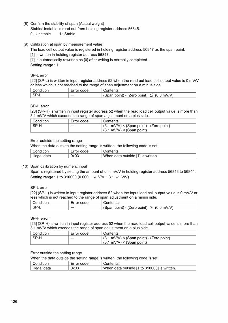
126
(8) Confirm the stability of span (Actual weight)
Stable/Unstable is read out from holding register address 56845.
0 : Unstable 1 : Stable
(9) Calibration at span by measurement value
The load cell output value is registered in holding register address 56847 as the span point.
[1] is written in holding register address 56847.
[1] is automatically rewritten as [0] after writing is normally completed.
Setting range : 1
SP-L error
[22] (SP-L) is written in input register address 52 when the read out load cell output value is 0 mV/V or less which is not reached to the range of span adjustment on a minus side.
Condition Error code Contents
SP-L - (Span point) - (Zero point) ≦ (0.0 mV/V)
SP-H error
[23] (SP-H) is written in input register address 52 when the read load cell output value is more than 3.1 mV/V which exceeds the range of span adjustment on a plus side.
Condition Error code Contents
SP-H - (3.1 mV/V) < (Span point) - (Zero point) (3.1 mV/V) < (Span point)
Error outside the setting range
When the data outside the setting range is written, the following code is set.
Condition Error code Contents
illegal data 0x03 When data outside [1] is written.
(10) Span calibration by numeric input
Span is registered by setting the amount of unit mV/V in holding register address 56843 to 56844.
Setting range : 1 to 310000 (0.0001 m V/V ~ 3.1 m V/V)
SP-L error
[22] (SP-L) is written in input register address 52 when the input load cell output value is 0 mV/V or less which is not reached to the range of span adjustment on a minus side.
Condition Error code Contents
SP-L - (Span point) - (Zero point) ≦ (0.0 mV/V)
SP-H error
[23] (SP-H) is written in input register address 52 when the read load cell output value is more than 3.1 mV/V which exceeds the range of span adjustment on a plus side.
Condition Error code Contents
SP-H - (3.1 mV/V) < (Span point) - (Zero point) (3.1 mV/V) < (Span point)
Error outside the setting range
When the data outside the setting range is written, the following code is set.
Condition Error code Contents
illegal data 0x03 When data outside [1 to 310000] is written.

127
(11) Finish calibration
The calibration data such as zero point and the span point that is registered temporary are stored in holding register address 56848 and returned to the measurement mode.
[1] is written in holding register address 56848.
[1] is automatically rewritten as [0] after writing is normally completed.
Error outside the setting range
When the data outside the setting range is written, the following code is set.
Condition Error code Contents
illegal data 0x03 When data outside [1] is written.
(12) Calibration forced finish.
When [0] is written in holding register address 56833 during the calibration procedure, the calibration is discontinued without storing the calibration data that is registered temporary, and you can return to the measurement mode.
15-1-2. Fine adjustment mode for Zero and Span
Each item of the flow chart corresponds to each procedure of [4-4. Details of procedure for
fine adjustment of Zero point and Span point].
Please refer [4-4. Details of procedure for fi ne adjustment of Zero point and Span point] for
the details.
・ While executing the calibration by transmission, (–RS–) is displayed.
・ When the calibration is compulsorily finished, all the data returns to the condition before the calibration without executing the registration.
・ Please register the data for the calibration with the weight after confirming the stable condition without fail.
(1) Change to the fi ne adjustment mode for Zero point and Span point
(2) Zero stability check
(3) Fine adjustment of zero point.
(4) Span stability check
(5) Fine adjustment of span point
(6) Finish of fine adjustment of zero point and span point

128
(1) Change to the fine adjustment mode for Zero point and Span point
Shift to fine adjustment mode of zero point and span point by writing [10] in holding register address 56833.
(2) Zero stability check
The weighing values are read out from holding register addresses 56857 to 56858.
Stable/Unstable is read out from holding register address 56845 with no load on the measuring section.
0 : Unstable 1 : Stable
(3) Fine adjustment of zero point
Zero the load values from holding register addresses 56857 to 56858.
Execute the fine adjustment after writing the data showing in below table in holding register address 56849.
Writing holding register address 56849
Fine adjustment at plus side 1
Corse adjustment at plus side 10
Fine adjustment at minus side -1
Corse adjustment at minus side -10
TE-L error
[20] (TE-L) is written in input register address 52 when the read load cell output value is less than -2.5 mV/V which exceeds the range of zero adjustment on a minus side.
Condition Error code Contents
TE-L 0x03 (Zero point) < (-2.5 mV/V)
TE-H error
[21] (TE-H) is written in input register address 52 when the read load cell output value is more than 2.5 mV/V which exceeds the range of zero adjustment on a plus side.
Condition Error code Contents
TE-H 0x03 (2.5 mV/V) < (Zero point) (3.1 mV/V) < (Span point)
Error outside the setting range
When the data outside the setting range is written, the following code is set.
Condition Error code Contents
illegal data 0x03 When data outside [1], [10], [-1] or [-10] is written.
(4) Span stability check
The load values are read out from holding register addresses 56857 to 56858.
Weights that can be loaded on the weighing section, not exceeding the weighing capacity, are placed and Stable/Unstable is read out from holding register address 56845.
0 : Unstable 1 : Stable

129
(5) Fine adjustment for Span
Adjust the display to match the weights loaded on the weighing section.
Execute the fine adjustment after writing the data showing in below table in holding register address 56850.
Writing holding register address 56850
Fine adjustment at plus side 1
Corse adjustment at plus side 10
Fine adjustment at minus side -1
Corse adjustment at minus side -10
SP-L error
[22] (SP-L) is written in input register address 52 when the input load cell output value is 0 mV/V or less which is not reached to the range of span adjustment on a minus side.
Condition Error code Contents
SP-L 0x03 (Span point) - (Zero point) ≦ (0.0 mV/V)
SP-H error
[23] (SP-H) is written in input register address 52 when the read load cell output value is more than 3.1 mV/V which exceeds the range of span adjustment on a plus side.
Condition Error code Contents
SP-H 0x03 (3.1 mV/V) < (Span point) - (Zero point) (3.1 mV/V) < (Span point)
Error outside the setting range
When the data outside the setting range is written, the following code is set.
Condition Error code Contents
illegal data 0x03 When data outside [1], [10], [-1] or [-10] is written.
(6) Finish of fi ne adjustment for Zero point and Span point
The adjusted data for zero point and the span point that is registered temporary are stored in holding register address 56848 and returned to the measurement mode.
[1] is written in holding register address 56848.
[1] is automatically rewritten as [0] after writing is normally completed.
Error outside the setting range
When the data outside the setting range is written, the following code is set.
Condition Error code Contents
illegal data 0x03 When data outside [1] is written.
(7) Calibration forced finish.
When [0] is written in holding register address 56833 during the calibration procedure, the calibration is discontinued without storing the calibration data that is registered temporary, and you can return to the measurement mode.

130
15-1-3. Calibration mode of digital linearization
Each item of the flow chart corresponds to each procedure of [4-5. Details of procedure for fine adjustment of Zero point and Span point].
Please refer [4-5. Details of procedure for fi ne adjustment of Zero point and Span point] for the details.
・ While executing the calibration by transmission, (–RS–) is displayed.
・ When the calibration is compulsorily finished, all the data returns to the condition before the calibration without executing the registration.
・ Please register the data for the calibration with the weight after confirming the stable condition without fail.
(1) Change to digital linearization mode
Shift to digital linearization mode by writing [11] in holding register address 56833.
(2) Stability check at point No. 1
Weights are placed for the point to be calibrated on the weighing section and Stable/Unstable is read out from holding register address 56845.
0 : Unstable 1 : Stable
(1) Change to digital linearization mode
(2) Stability check at point No.1
(3) Compensation at point No.1
(4) Stability check at point No.2
(5) Compensation at point No.2
(6) Stability check at point No.3
(7) Compensation at point No.3
(8) Finish the digital linearization mode

131
(3) Compensation by 1 point
The weight amount at point No.1 is set and registered in holding register address 56851 to 56852.
Setting range : 1 to Maximum display value
LN-L error
[24] (LN-L) is written in input register address 52 when input load value is lower than zero point.
Condition Error code Contents
LN-L - (Value at Point No.1) < (Zero point)
LN-H error
[25] (LN-H) is written in input register address 52 when input load value is higher than weighing capacity.
Condition Error code Contents
LN-H - (Span point) < (Value at Point No.1)
Error outside the setting range
When the data outside the setting range is written, the following code is set.
Condition Error code Contents
illegal data 0x03 When data outside [1] to [Maximum display value] is written.
(4) Stability check at point No. 2
Weights are placed for the point to be calibrated on the weighing section and Stable/Unstable is read out from holding register address 56845.
0 : Unstable 1 : Stable
(5) Compensation by 2 points
After putting the weight of the point which should be compensated on the measuring part, the weight amount at point No.2 is set and registered in holding register address 56853 to 56854.
Setting range : 1 to Maximum display value
LN-L error
[24] (LN-L) is written in input register address 52 when input load value is lower than zero point.
Condition Error code Contents
LN-L - (Value at Point No.2) < (Value at Point No.1)
LN-H error
[25] (LN-H) is written in input register address 52 when input load value is higher than weighing capacity.
Condition Error code Contents
LN-H - (Span point) < (Value at Point No.2)
Error outside the setting range
When the data outside the setting range is written, the following code is set.
Condition Error code Contents
illegal data 0x03 When data outside [1] to [Maximum display value] is written.

132
(6) Stability check at point No. 3
Weights are placed for the point to be calibrated on the weighing section and Stable/Unstable is read out from holding register address 56845.
0 : Unstable 1 : Stable
(7) Compensation by 3 points
After putting the weight of the point which should be compensated on the measuring part, the
weight amount at point No.3 is set and registered in holding register address 56855 to 56856.
Setting range : 1 to Maximum display value
LN-L error
[24] (LN-L) is written in input register address 52 when input load value is lower than zero point.
Condition Error code Contents
LN-L - (Value at Point No.3) < (Value at Point No.2)
LN-H error
[25] (LN-H) is written in input register address 52 when input load value is higher than weighing capacity.
Condition Error code Contents
LN-H - (Span point) < (Value at Point No.3)
Error outside the setting range
When the data outside the setting range is written, the following code is set.
Condition Error code Contents
illegal data 0x03 When data outside [1] to [Maximum display value] is written.
(8) Finish the digital linearization mode
The adjusted data for compensation value of digital linearization that is registered temporary are stored in holding register address 56848 and returned to the measurement mode.
[1] is written in holding register address 56848.
[1] is automatically rewritten as [0] after writing is normally completed.
Error outside the setting range
When the data outside the setting range is written, the following code is set.
Condition Error code Contents
illegal data 0x03 When data outside [1] is written.
(9) Calibration forced finish.
When [0] is written in holding register address 56833 during the calibration procedure, the calibration is discontinued without storing the calibration data that is registered temporary, and you can return to the measurement mode.
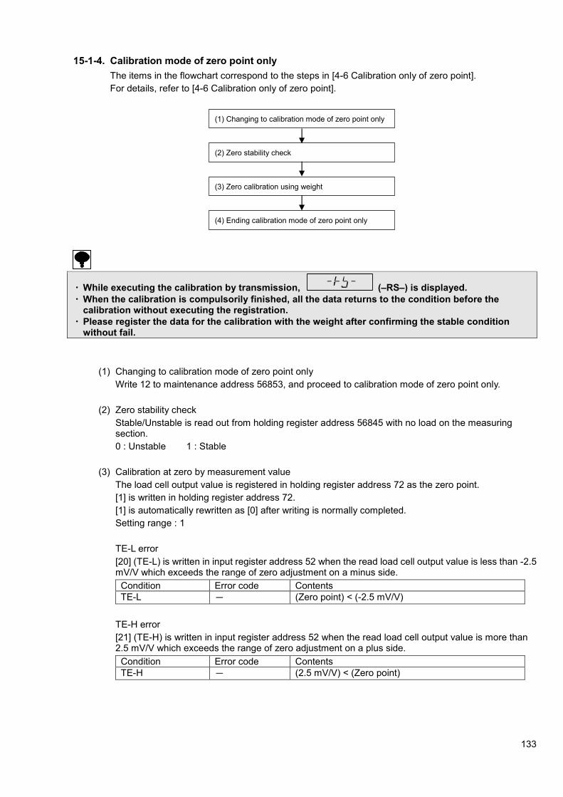
133
15-1-4. Calibration mode of zero point only
The items in the flowchart correspond to the steps in [4-6 Calibration only of zero point].
For details, refer to [4-6 Calibration only of zero point].
・ While executing the calibration by transmission, (–RS–) is displayed.
・ When the calibration is compulsorily finished, all the data returns to the condition before the calibration without executing the registration.
・ Please register the data for the calibration with the weight after confirming the stable condition without fail.
(1) Changing to calibration mode of zero point only
Write 12 to maintenance address 56853, and proceed to calibration mode of zero point only.
(2) Zero stability check
Stable/Unstable is read out from holding register address 56845 with no load on the measuring section.
0 : Unstable 1 : Stable
(3) Calibration at zero by measurement value
The load cell output value is registered in holding register address 72 as the zero point.
[1] is written in holding register address 72.
[1] is automatically rewritten as [0] after writing is normally completed.
Setting range : 1
TE-L error
[20] (TE-L) is written in input register address 52 when the read load cell output value is less than -2.5 mV/V which exceeds the range of zero adjustment on a minus side.
Condition Error code Contents
TE-L - (Zero point) < (-2.5 mV/V)
TE-H error
[21] (TE-H) is written in input register address 52 when the read load cell output value is more than 2.5 mV/V which exceeds the range of zero adjustment on a plus side.
Condition Error code Contents
TE-H - (2.5 mV/V) < (Zero point)
(1) Changing to calibration mode of zero point only
(2) Zero stability check
(3) Zero calibration using weight
(4) Ending calibration mode of zero point only
134
Error outside the setting range
When the data outside the setting range is written, the following code is set.
Condition Error code Contents
illegal data 0x03 When data outside [1] is written.
(4) Changing to calibration mode at zero point only
The calibration data such as zero point and the span point that is registered temporary are stored in holding register address 56848 and returned to the measurement mode.
[1] is written in holding register address 56848.
[1] is automatically rewritten as [0] after writing is normally completed.
Error outside the setting range
When the data outside the setting range is written, the following code is set.
Condition Error code Contents
illegal data 0x03 When data outside [1] is written.
(5) Calibration forced finish.
When [0] is written in holding register address 51 during the calibration procedure, the calibration is discontinued without storing the calibration data that is registered temporary, and you can return to the measurement mode.

135
16. Options 16-1. Analog output
16-1-1. Current output specifications (model: CSD903-P07)
Specifications Content
Output DC4 mA ~ 20 mA
Load characteristic 510 ohm or less
Non linearity 0.02 %F.S.
Resolution Approx. 1/12000 or more
Over range Approx. DC2.4 mA, [-OL] displayed. Approx. DC21.6 mA, [OL] displayed.
Output rate 4 times/s, 20 times/s
16-1-2. Voltage output specifications (model: CSD903-P25)
Specifications Content
Output DC0 V ~ 10 V
Load characteristic 5 k-ohm or more
Non linearity 0.02 %F.S.
Resolution Approx. 1/12000 or more
Over range Approx. DC-1 V, [-OL] displayed. Approx. DC11, [OL] displayed.
Output rate 4 times/s, 20 times/s
・ The analog output of this unit executes rewriting the output synchronizing with the display.
・ The internal circuit and photo-coupler is insulated.
・ After turning on the power supply, the analog output has the output change element. Please turn on the power supply for about one hour before to use it in stable condition.
16-1-3. Connection of analog output
(1) Current output
A
Shield
- +
Load resistance 510 ohm or less

136
(2) Voltage output
・ For the connection with the analog output, be sure to apply the shielded cable and shield should be
connected with F.G terminal.
・ To comply the instrument with the CE conformity or applied JIS standard, please use shielded cable and connect the shield with the F.G. terminal.
16-1-4. Analog output target
The analog output target is selected by C function CF-70.
The analog output target can be selected from [Display interlock], [Gross value] and [Net value].
Default is set to [Display interlock].
V
Shield
- +
Load resistance 5 k-ohm or more

137
16-1-5. Scaling of analog output
The analog output is set as the minimum value ~ the maximum value by 0 to 10 000.
This can be made any value by changing CF-71 and CF-72.
CF-71 set the display when the minimum value is output.
CF-72 set the display when the maximum value is output.
・ The setting of CF-72 must not exceed the weighing capacity set in clause 4.
・ Please set the smaller value in CF-71 than the value set in CF-72.
最大表示表示
最大表示の+ 110 %
アナログ出力
約21.6 mA約11 V
最大値 20 mA10 V
最小値 4 mA0 V 0表示
約2.4 mA約-1 V
ー1表示
Analog output
Display The maximum display
+9D of the maximum display
Display
Approx.2.4 mA
Approx. –1 V
-20D display
the maximum display
The minimum display
Approx.21.6 mA
Approx.11 V

138
Scaling of analog output when set value of CF-03 is set to 0 or 1.
CF-71 set the display when the minimum value is output.
CF-72 set the display when the maximum value is output.
Ex) CF-71: set as 1 000
CF-72: set as 5 000
When the display is 5 000, the maximum value is output.
When the display is 1 000, the minimum value is output.
・ The setting of CF-72 must not exceed the weighing capacity set in clause 4.
・ Please set the smaller value in CF-71 than the value set in CF-72.
最大表示表示
最大表示の+110 %
アナログ出力
約21.6 mA約11 V
最大値 20 mA10 V
最小値 4 mA0 V 0表示
約2.4 mA約-1 V
最大表示の-10 %
Display
+110 % of the maximum displayThe maximum display
+110 % of the maximum display
Display
Approx.2.4 mA Approx. –1 V
-10 % of the maximum display
the maximum display
Approx.21.6 mA Approx. 11 V
The minimum display
Analog output
5 000表示
5 500
アナログ出力
約21.6 mA約11 V
最大値 20 mA10 V
最小値 4 mA0 V 1 000
約2.4 mA約-1 V
最大表示の-10 %
Analog output
Approx.21.6 mA Approx. 11 V
the maximum display
-10 % of the maximum display
The minimum display
Approx.2.4 mA Approx. –1 V
Display

139
16-1-6. Fine adjustment of analog output
After the analog output scaling is executed by setting C function CF-71 and CF-72, the fine adjustment is executed by the trimmer ZERO and the trimmer SPAN.
The range of the fine adjustment is approx.±10 % against the full scale.
ZERO trimmer SPAN trimmer
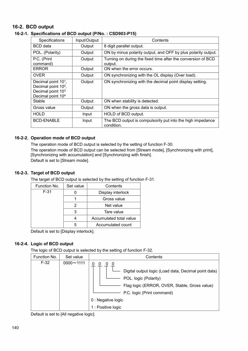
140
16-2. BCD output
16-2-1. Specifications of BCD output (P/No. : CSD903-P15)
Specifications Input/Output Contents
BCD data Output 8 digit parallel output.
POL. (Polarity) Output ON by minus polarity output, and OFF by plus polarity output.
P.C. (Print command)
Output Turning on during the fixed time after the conversion of BCD output.
ERROR Output ON when the error occurs.
OVER Output ON synchronizing with the OL display (Over load).
Decimal point 101, Decimal point 102, Decimal point 103 Decimal point 104
Output ON synchronizing with the decimal point display setting.
Stable Output ON when stability is detected.
Gross value Output ON when the gross data is output.
HOLD Input HOLD of BCD output.
BCD-ENABLE Input The BCD output is compulsorily put into the high impedance condition.
16-2-2. Operation mode of BCD output
The operation mode of BCD output is selected by the setting of function F-30.
The operation mode of BCD output can be selected from [Stream mode], [Synchronizing with print], [Synchronizing with accumulation] and [Synchronizing with finish].
Default is set to [Stream mode].
16-2-3. Target of BCD output
The target of BCD output is selected by the setting of function F-31.
Function No. Set value Contents
F-31 0 Display interlock
1 Gross value
2 Net value
3 Tare value
4 Accumulated total value
5 Accumulated count
Default is set to [Display interlock].
16-2-4. Logic of BCD output
The logic of BCD output is selected by the setting of function F-32.
Function No. Set value Contents
F-32 0000~1111 0 0 0 0
Digital output logic (Load data, Decimal point data)
POL. logic (Polarity)
Flag logic (ERROR, OVER, Stable, Gross value)
P.C. logic (Print command)
0 : Negative logic
1 : Positive logic
Default is set to [All negative logic].

141
16-2-5. Width of P.C. (Print command)
The width of print command is selected by the setting of function F-33.
The width of print command is selected from [125 ms], [25 ms] and [5 ms].
Default is set to [25 ms].
The print command becomes unstable in the starting period because of converting the BCD data. Please read correct BCD data according to the timing of the falling down of the print command.
16-2-6. BCD output times
The times of the BCD output is selected by the setting of function F-34.
The time of the BCD output is selected from [100 times/s], [20 times/s] and [4 times/s].
Default is set to [4 times/s].
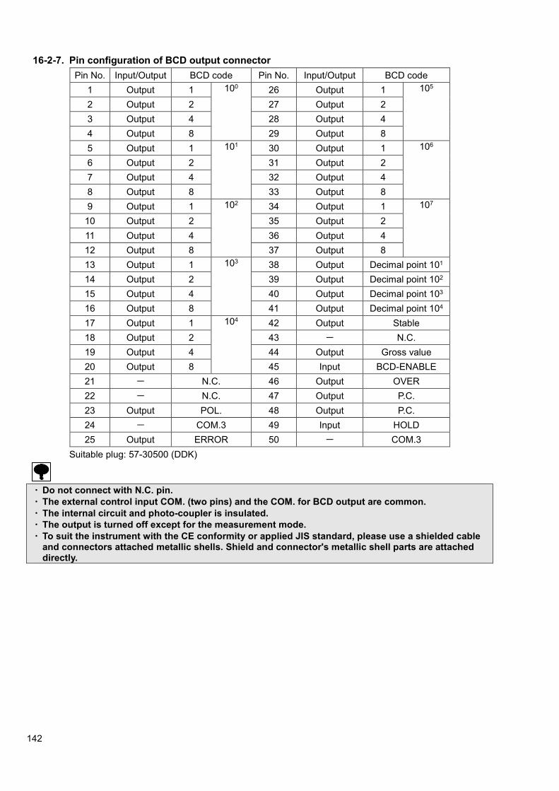
142
16-2-7. Pin configuration of BCD output connector
Pin No. Input/Output BCD code Pin No. Input/Output BCD code
1 Output 1 100 26 Output 1 105
2 Output 2 27 Output 2
3 Output 4 28 Output 4
4 Output 8 29 Output 8
5 Output 1 101 30 Output 1 106
6 Output 2 31 Output 2
7 Output 4 32 Output 4
8 Output 8 33 Output 8
9 Output 1 102 34 Output 1 107
10 Output 2 35 Output 2
11 Output 4 36 Output 4
12 Output 8 37 Output 8
13 Output 1 103 38 Output Decimal point 101
14 Output 2 39 Output Decimal point 102
15 Output 4 40 Output Decimal point 103
16 Output 8 41 Output Decimal point 104
17 Output 1 104 42 Output Stable
18 Output 2 43 - N.C.
19 Output 4 44 Output Gross value
20 Output 8 45 Input BCD-ENABLE
21 - N.C. 46 Output OVER
22 - N.C. 47 Output P.C.
23 Output POL. 48 Output P.C.
24 - COM.3 49 Input HOLD
25 Output ERROR 50 - COM.3
Suitable plug: 57-30500 (DDK)
・ Do not connect with N.C. pin.
・ The external control input COM. (two pins) and the COM. for BCD output are common.
・ The internal circuit and photo-coupler is insulated.
・ The output is turned off except for the measurement mode.
・ To suit the instrument with the CE conformity or applied JIS standard, please use a shielded cable and connectors attached metallic shells. Shield and connector's metallic shell parts are attached directly.

143
16-2-8. Equivalent circuit of input/output
16-2-9. Timing chart
(1) Normal
At the time of data output of each P.C., DATA and POL., output transistor will become ON (Negative logic electrically).
(2) When the data is over
At the time of OVR output, output transistor will at the OVER signal will become ON (Negative logic electrically). Moreover, for all of the DATA, output transistor will become OFF (Positive logic electrically) at the time of OVER output. (However, for the POL., normal OFF at the [OL], and normal ON
at the [----OL]).
DATA
POL.
P.C.
OVER
ON
ON
ON ON ON ON ON
Input section Output section
VCE=DC30 V IC=DC20 mA MAX
3 3
DATA
POL.
P.C.
ON ON
ON ON ON ON
ON ON
4 Times/s:Approx. 125 ms/ Approx. 25 ms/ Approx. 5 ms changeable 20 Times/s:Approx. 25 ms/ Approx. 5ms changeable 100 Times/s:Approx. 5 ms
4 Times/s:Approx. 250 ms 20 Times/s:Approx. 50 ms 100 Times/s:Approx. 10 ms
4 times/s : Approx. 250 ms 20 times/s : Approx. 50 ms 100 times/s : Approx. 10 ms
4 times/s : Approx. 125 ms / Approx. 25 ms / Approx. 5 ms changeable. 20 times/s : Approx. 25 ms / Approx. 5 ms changeable. 100 times/s : Approx. 5 ms

144
(3) When error is occurred
At the time of ERROR output, output transistor at ERROR signal will become ON (Negative logic electrically). Moreover, for each DATA, POL., all of the output transistor will become OFF at the time of ERROR output (Positive logic electrically).
(4) When the hold signal is input
・ The input operation of HOLD signal is executed after the short circuit for approx. 100 ms or more.
・ At the time of HOLD signal input, the output transistor of P.C. will be OFF condition (Positive logic electrically). However, as for P.C., OFF condition will be made after one (1) shot of operation.
16-2-10. Output condition
Setting output logic Output data Condition of
transistor
Pin-COM level at
the time of voltage
supply externally.
Negative logic Yes ON L
No OFF H
Positive logic Yes OFF H
No ON L
DATA
POL.
P.C.
ERROR
ON ON ON
ON
ON ON
ON ON ON ON ON
ON
HOLD
P.C.
POL.
DATA

145
16-3. RS-232C and RS-422/485 interface
16-3-1. Specifications for RS-232C interface (P/N: CSD903-P74)
Specification Contents
Communication method Half duplex
Synchronous method Start-stop synchronous method
Baud rate Selectable from 1 200, 2 400, 4 800, 9 600, 19 200 and 38 400 bps
Data bit length Selectable from 7 bit and 8 bit
Parity bit Selectable from No-parity,Even parity and Odd parity.
Stop bit Selectable from 1 bit and 2 bit
Terminator Selectable from CR+LF and CR
Transmission data ASCII code
Cable length Within 15 m.
Input/Output monitor With LED (TXD and RXD)
16-3-2. RS-422/485 interface specifications (P/N: CSD903-P76)
Specification Contents
Communication method Half duplex
Synchronous method Start-stop synchronous method
Baud rate Selectable from 1 200, 2 400, 4 800, 9 600, 19 200 and 38 400 bps
Data bit length Selectable from 7 bit and 8 bit
Parity bit Selectable from none, Even parity and Odd parity.
Stop bit Selectable from 1 bit and 2 bit
Terminator Selectable from CR+LF and CR
Transmission data ASCII code
Cable length Approx. 1 km
Address Select one from 0 to 31
No. of connectable unit 32 units at maximum (RS-422 : 10 units)
Termination resistance Built-in (Yes/No is selectable by the connection of terminal boards.)
Input / Output monitor With LED (TXD and RXD)
16-3-3. Operating mode of RS-232C and RS-422/485
The operation mode of RS-232C is selected by the setting of function F-40.
The operation mode of RS-232C is selectable from [Command mode], [Stream mode] and [Synchronized with print]. Default is selected as [Command mode].
The operation mode of RS-422/485 is selected by the setting of the function F-49.
The operation mode of RS-422/485 is selectable from [Command mode], and [Stream mode].
Default is selected as [Command mode].
When you select the stream mode, the data keeps being output at constant intervals. Also, control from the host becomes impossible.

146
(1) Command mode
Data is sent back from CSD-903 to the host side according to the command/data by sending the command/data to CSD-903 provided by the host (personal computer or sequencer, etc.). Please communicate according to the following procedure.
(2) Stream mode
When RS-232C, RS-422/485 is used, it keeps outputting the latest data of the output target selected by function F-41. However, the output frequency changes by setting the baud rate.
(3) Synchronizing with print
When RS-232C is used, the data of the output target selected by function F-41 is output synchronizing with the print signal (F key, external control input, and automatic print).
・ The communicating operation is executed only in the measurement mode. The error code is
transmitted in the other mode.
・ It does not respond in the stand-by condition.
・ The flow control is not executed in the CSD-903.
・ The CTS/RTS signal isn't applied.
・ The X flow control isn't performed.
・ The communication operation is an interactive mode.
16-3-4. Output target at synchronizing with RS-232C print in stream mode RS-232C and
RS-422/485
The output target of RS-232C and RS-422/485 is selected by the setting of function F-41.
The output target of RS-232C and RS-422/485 is selectable from [Display interlock], [Gross value], [Net value], or [Conditional load display data].
Default is set as [Display interlock].
・ When RS-232C interface is equipped with, the setting of function F-41 becomes valid under the
setting of function F-40 being [1~4].
・ When RS422/485 interface is equipped with, this becomes valid under the setting of function F-49 being [1].
Start
Command/Data
Data
Host→CSD-903
CSD-903→Host

147
16-3-5. Specifications of communication by RS-232C and RS-422/485
The specification of the communication by RS-232C or RS-422/485 is selected by function F-42.
Function No. Set value Contents
F-42 00000 ~ 15121
0 0 0 0 0
Data bit length 0: 7 bit or 1: 8 bit
Parity bit 0: No parity
1: Even parity 2: Odd parity
Stop bit 0: 1 bit or 1: 2 bit
Baud rate 0: 1 200 bps, 1: 2 400 bps 2: 4 800 bps, 3: 9 600 bps 4: 19 200 bps, 5: 38 400 bps
Terminator 0: CR or 1: CR+LF
Default is set to [13020].
16-3-6. Address setting of RS-422/485
The address setting of RS-422/485 is set by the setting of function F-43.
Setting range: 00 ~ 31
Default is set to [00].
16-3-7. Changeover of RS-422/485
The changeover of RS-422 and RS-485 is executed by the setting of function F-44.
Default is set to [RS-422].
16-3-8. Delay time of RS-485 return data
When the transmitting terminal on the host side enters the state of low impedance after the host side transmission ends, the return data of the CSD-904 side can be delayed.
The delay time of RS-485 return data is set by the function F-45.
Setting range : 0~9, Unit : 0.1 s
Default is set to [1].
16-3-9. Transmission data decimal point existence of RS-232C and RS-422/485
The transmission data decimal point existence of RS-232C is selected by function F-46.
Default is set to [No decimal point].

148
16-3-10. Pin configuration of RS-232C connector
Pin No. Signal Name
1 CD
2 TXD
3 RXD
4 N.C.
5 S.G.
6 N.C.
7 RTS
8 CTS
9 N.C.
Suitable plug: DE-9S-NR by JAE or equivalent. ※Not attached.
・ The screws for the fixing base of plug at the connector of RS-232C interface is inch type thread.
・ Do not connect with N.C. pin.
・ The internal circuit and photo-coupler is insulated.
・ The external control in put COM. (two pins) and S.G. for RS-232C are common.
・ The internal circuit and photo-coupler is insulated.
・ To suit the instrument with the CE conformity or applied JIS standard, please use a shielded cable and connectors attached metallic shells. Shield and connector's metallic shell parts are attached directly.
(1) Wiring of RS-232C No.1
CSD-903 Host (25pins)
1 CD 1 F.G.
2 TXD 2 TXD
3 RXD 3 RXD
4 N.C. 4 RTS
5 S.G. 5 CTS
6 N.C. 6 DSR
7 RTS 7 S.G.
8 CTS 8 DCD
9 N.C. 9
~
19
20 DTR
21
~
25
(2) Wiring of RS-232C No.2
CSD-903 Host (9pins)
1 CD 1 DCD
2 TXD 2 RXD
3 RXD 3 TXD
4 N.C. 4 DTR
5 S.G. 5 S.G.
6 N.C. 6 DSR
7 RTS 7 RTS
8 CTS 8 CTS
9 N.C. 9 RI

149
16-3-11. Pin configuration of RS-422/485 terminals
SDA Difference output (+)
SDB Difference output (-)
RDA Difference input(+)
RDB Difference input(-)
TRM Cable end resistance
S.G. Signal ground
・ Please connect the internal terminating resistance by shortening between the TRM terminal and
RDB terminal which is the furthest from the host. (personal computer, sequencer, etc).
・ For the connection, we recommend to apply twisted pair wires.
・ The external control input COM. (two pins) and the S.G. for RS-422/485 are common.
・ Internal circuit and photo-coupler is insulated.
・ To suit the instrument with the CE conformity or applied JIS standard, please use a shielded cable and connect the shield to the serial interface output terminal board.
(1) Wiring of 1 to 1
RDA
RDB
SDA
SDB
S.G.
SDA
SDB
RDA
RDB Address 00
TRM.
S.G.
SDA
SDB
RDA
RDB Address 00
TRM.
S.G.
RDA
RDB
SDA
SDB
S.G.
RS-422 Host
RS-485 Host
CSD-903
CSD-903

150
(2) Wiring of 1 to n
・ There may have no S.G depends on the equipment on the host side.
・ The polarity of the signal of the host computer may have an opposite case depending on the instrument.
・ Depending on the instrument at the side of host, there may have the case of no SG terminal.
・ For the connection, we recommend you to use twist pair wires.
RDA
RDB
SDA
SDB
S.G.
0
Conect the cable end resistance at the remote place from the host.
SDA
SDB
RDA
RDB Address 01
TRM.
S.G.
SDA
SDB
RDA
RDB Address 09
TRM.
S.G.
SDA
SDB
RDA
RDB Address 00
TRM.
S.G.
RS-422 Host CSD-903
CSD-903
CSD-903
RDA
RDB
SDA
SDB
S.G.
Conect the cable end resistance at the remote place from the host.
SDA
SDB
RDA
RDBAddress 31
TMR
S.G.
SDA
SDB
RDA
RDB Address 01
TRM.
S.G.
SDA
SDB
RDA
RDB Address 00
TRM.
S.G.
RS-485 Host CSD-903
CSD-903
CSD-903
Connect the terminal resistance at the furthest from the host
Connect the terminal resistance at the furthest from the host

151
16-3-12. Data format of command mode
・ The address becomes [00] fixation for the RS-232C interface.
・ The load data enters from the right.
・ The sign of [-] for minus and [+] for plus is entered.
・ The load data performs zero suppress.
・ The decimal point adheres to a specified position when the decimal point is set with F-46 and when decimal point is specified with CF-01.
・ The decimal point adheres to a specified position when the decimal point is set with F-46 and when decimal point is specified with CF-01.
・ The empty sections are all spaces.
・ The display range of command number 24 accumulation value readout (8 digits) is from –19 999 999 to 99 999 999. The display range of command number 27 accumulation value readout (10 digits) is from –9 999 999 999 to 9 999 999 999.
(1) Reading out the load data (Host → CSD-903)
When command number is from 20 to 25
2 4 6
@ 0 0 2 2 Terminator
Return (CSD-903 → Host)
2 4 6 8 10 12 14
@ 0 0 2 2 - 1 2 3 Terminator
2 4 6 8 10 12 14
@ 0 0 2 2 + 0 . 1 2 3 Terminator
2 4 6 8 10 12 14
@ 0 0 2 2 + O L Terminator
2 4 6 8 10 12 14
@ 0 0 2 2 Terminator
Address
00 to 31
Address
00 to 31
Address
00 to 31
Address
00 to 31 Command No.
Command No.
24
25
26
Operation
Reading out accumulation value (8 digits)
Reading out accumulation times
Reading out conditional load display data
20
23
Reading out load data
Reading out gross value
Reading out net value
Reading out tare value
21
22
27 Reading out accumulation value (10 digits)
Address
00 to 31 Load data
Command No.
Sign of load data

152
2 4 6 8 10 12 14
@ 0 0 2 2 - O L Terminator
When command number is 26
2 4 6
@ 0 0 2 6 Terminator
Return (CSD-903 → Host)
2 4 6 8 10 12 14 16 18 20 22
@ 0 0 2 6 C1 C2 , C3 C4 , C5 C6 C7 C8 C9 C10
C11
C12
C13
C14
C15
Terminator
Header 1 Header 2 Sign Load data 8 digit Unit
C1 C2 Contents C3 C4 Contents C5 Contents C6 C7 C8 C9 C10 C11 C12 C13 C14 C15 Contents
O L Over load N T Net value + Plus 1 2 3 g gram
S T Stable G S Gross value - Minus 0 . 1 2 3 k g Kilo-gram
U S Unstable O L t ton
l b pound
N Newton
k N Kilo-Newton
When command number is 27
2 4 6
@ 0 0 2 6 Terminator
Return (CSD-903 → Host)
2 4 6 8 10 12 14 16
@ 0 0 2 7
Terminator
Address
00 to 31
Address
00 to 31 Command No.
Header 1 Header 2 Sign Load data 8 digit Unit
Address
00 to 31 Command No.
Address
00 to 31
Command No.
Sign Setting value

153
(2) Reading out the measurement setting data (Host → CSD-903)
2 4 6
@ 0 0 3 0 Terminator
Return (CSD-903 → Host)
2 4 6 8 10 12 14
@ 0 0 3 0 Terminator
(3) Reading out the comparison data (Host → CSD-903)
2 4 6
@ 0 0 3 0 Terminator
Return (CSD-903 → Host)
2 4 6 8 10 12 14
@ 0 0 3 0 Terminator
Address
00 to 31
Command No.
Sign Setting value
Address
00 to 31 Command No.
Address
00 to 31
Command No.
Sign Setting value
Address
00 to 31 Command No.
Command No.
30
36
31
32
33
Operation
Reading out S1 setting
Reading out S4 setting
Reading out S3 setting
Reading out S2 setting
Reading out Full
38
37 Reading out near zero
Reading out tare
39 Reading out effective brand number
3A Reading out setting brand number
Operation
Reading out fixed value (SET1)
Reading out preset tare weight value
Command No.
30
38
Reading out free fall (SET2)
Reading out prior to fixed value 1 (SET3)
Reading out prior to fixed value 2 (SET4)
Reading out over (SET5)
Reading out under (SET6)
Reading out full (SET8)
Reading out near zero (SET7)
36
31
32
33
34
35
37
Reading out effective brand number 39
Reading out setting brand number 3A
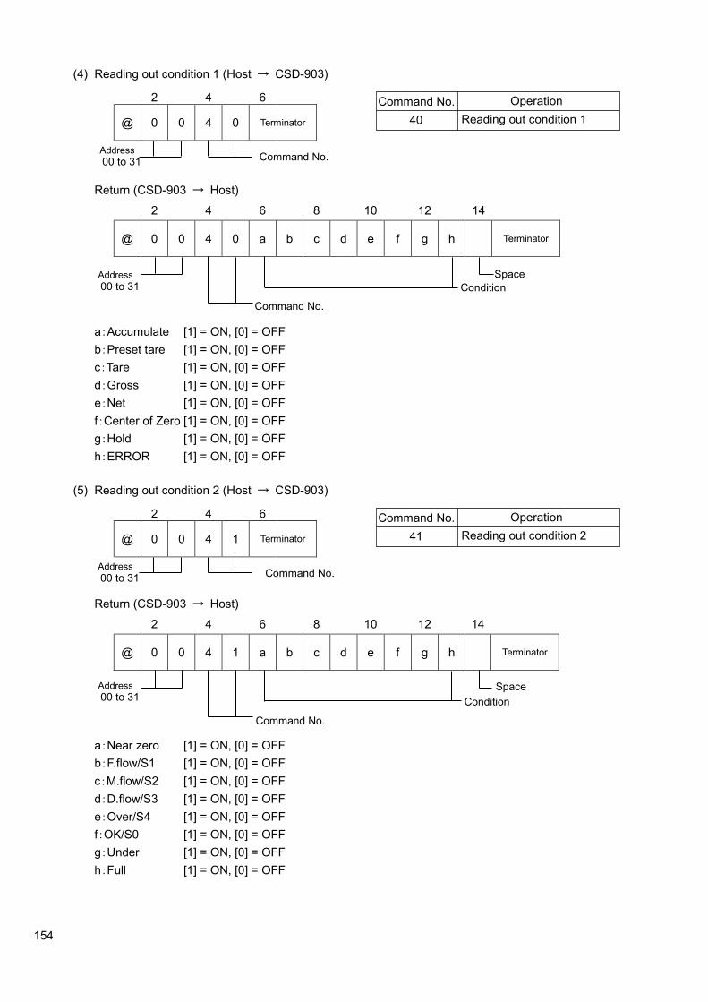
154
(4) Reading out condition 1 (Host → CSD-903)
2 4 6
@ 0 0 4 0 Terminator
Return (CSD-903 → Host)
2 4 6 8 10 12 14
@ 0 0 4 0 a b c d e f g h Terminator
a:Accumulate [1] = ON, [0] = OFF
b:Preset tare [1] = ON, [0] = OFF
c:Tare [1] = ON, [0] = OFF
d:Gross [1] = ON, [0] = OFF
e:Net [1] = ON, [0] = OFF
f:Center of Zero [1] = ON, [0] = OFF
g:Hold [1] = ON, [0] = OFF
h:ERROR [1] = ON, [0] = OFF
(5) Reading out condition 2 (Host → CSD-903)
2 4 6
@ 0 0 4 1 Terminator
Return (CSD-903 → Host)
2 4 6 8 10 12 14
@ 0 0 4 1 a b c d e f g h Terminator
a:Near zero [1] = ON, [0] = OFF
b:F.flow/S1 [1] = ON, [0] = OFF
c:M.flow/S2 [1] = ON, [0] = OFF
d:D.flow/S3 [1] = ON, [0] = OFF
e:Over/S4 [1] = ON, [0] = OFF
f:OK/S0 [1] = ON, [0] = OFF
g:Under [1] = ON, [0] = OFF
h:Full [1] = ON, [0] = OFF
Address
00 to 31 Command No.
Command No.
40
Operation
Reading out condition 1
Address
00 to 31
Command No.
Condition
Space
Address
00 to 31 Command No.
Command No.
41
Operation
Reading out condition 2
Address
00 to 31
Command No.
Condition
Space

155
(6) Reading out condition 3 (Host → CSD-903)
2 4 6
@ 0 0 4 2 Terminator
Return (CSD-903 → host)
2 4 6 8 10 12 14
@ 0 0 4 2 a b c d e f g h i Terminator
a:N.C.
b:DISCHARGE (GATE OPEN) [1] = ON, [0] = OFF
c:BATCH FINISH [1] = ON, [0] = OFF
d:N.C.
e:DISCHARGE FINISH [1] = ON, [0] = OFF
f:N.C.
g:N.C.
h:During measuring [1] = ON, [0] = OFF
i:Sequence ERROR [0] = No ERROR, [1 ~ a] = Sequence ERROR No.
Refer to [20.Sequence error].
(7) Reading out ROM version (Host → CSD-903)
2 4 6
@ 0 0 4 5 Terminator
At normal operation
Return (CSD-903 → host)
2 4 6 8 10 12 14
@ 0 0 4 5 V Terminator
At abnormal operation
Return (CSD-903 → host)
2 4 6 8
@ 0 0 E R 0 2 Terminator
Address
00 to 31 Command No.
Command No.
42
Operation
Reading out condition 3
Address
00 to 31
Command No.
Condition
Address
00 to 31 Command No.
Command No.
45
Operation
Reading out ROM version
Address
00 to 31
Command No.
ROM version
Address
00 to 31

156
(8) Change of condition (Host → CSD-903)
2 4 6
@ 0 0 5 0 Terminator
At normal operation
Return (CSD-903 → Host)
2 4 6
@ 0 0 5 0 Terminator
At abnormal operation
Return (CSD-903 → Host)
2 4 6 8
@ 0 0 E R 0 2 Terminator
The error is transmitted under the following condition:
・ When you cannot execute the zero set outside the effective range when zero set by command NO.52 is executed.
・ When you cannot execute the tare weight cancellation due to the [±±±±OL] display when tare weight
cancellation by [Command NO.54] is executed.
・ When you cannot execute the accumulation because the accumulating value overflowed, when the accumulation by command NO.5C is executed.
Address
00 to 31 Command No.
Address
00 to 31 Command No.
Address
00 to 31
Command No.
56
52
53
54
55
Operation
ZERO
Zero clear
Tare
Tare clear
Batch start
Clear the last accumulated data
Accumulation clear
Error cancellation
Emergency stop
5D
5E
5I
5J
Discharge start
Accumulation command
58
5C
50
51
GROSS DISPLAY
NET DISPLAY
5F Accumulation clear for all brands

157
(9) Writing the measurement setting data (Host → CSD-903)
2 4 6 8 10 12 14
@ 0 0 6 0 Terminator
At normal operation
Return (CSD-903 → host)
2 4 6 8 10 12 14
@ 0 0 6 0 Terminator
At abnormal operation
Return (CSD-903 → host)
2 4 6 8
@ 0 0 E R 1 3 Terminator
・ Please enter the set value by right justify.
・ Please do not put the decimal point.
・ Please set the stored place to the internal RAM when the set value is continuously changed, and the rewriting time of EEPROM might exceed about one million times.
・ Please do not change in the set value under the measurement because the A/D sampling rate decreases temporarily while rewriting the set value. Please set the storing place to the internal ROM when you change the set value during the measurement.
・ To write the effective brand number for [Command No. 69], set function F-51 to [2].
・ Measurement setting data writing allows the setting to be changed for the brand number selected by the setting brand number in [Command No. 6A].
Address
00 to 31
Command No.
Sign Setting value
Address
00 to 31
Command No.
Sign
Setting value
Address
00 to 31
Command No.
60
66
61
62
63
64
65
Operation
Writing fixed value (SET1)
Writing free fall (SET2)
Writing prior to fixed value 1 (SET3)
Writing prior to fixed value 2 (SET4)
Writing over (SET5)
Writing under (SET6)
Writing full (SET8)
68
67 Writing near zero (SET7)
Writing tare
69 Writing effective brand number
6A Writing setting brand number
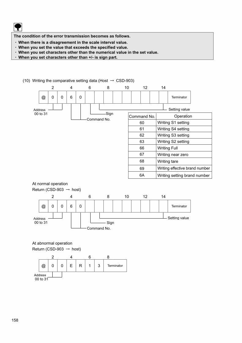
158
The condition of the error transmission becomes as follows.
・ When there is a disagreement in the scale interval value.
・ When you set the value that exceeds the specified value.
・ When you set characters other than the numerical value in the set value.
・ When you set characters other than +/- is sign part.
(10) Writing the comparative setting data (Host → CSD-903)
2 4 6 8 10 12 14
@ 0 0 6 0 Terminator
At normal operation
Return (CSD-903 → host)
2 4 6 8 10 12 14
@ 0 0 6 0 Terminator
At abnormal operation
Return (CSD-903 → host)
2 4 6 8
@ 0 0 E R 1 3 Terminator
Address
00 to 31
Command No.
Sign Setting value
Address
00 to 31
Command No.
Sign
Setting value
Address
00 to 31
Command No.
60
66
61
62
63
Operation
Writing S1 setting
Writing S4 setting
Writing S3 setting
Writing S2 setting
Writing Full
68
67 Writing near zero
Writing tare
69 Writing effective brand number
6A Writing setting brand number

159
・ Please enter the set value by right justify.
・ Please do not put the decimal point.
・ Please set the stored place to the internal RAM when the set value is continuously changed, and the rewriting time of EEPROM might exceed about one million times.
・ Please do not change in the set value under the measurement because the A/D sampling rate decreases temporarily while rewriting the set value. Please set the storing place to the internal ROM when you change the set value during the measurement.
・ To write the effective brand number for [Command No. 69], set function F-51 to [2].
・ Comparison value setting data writing allows the setting to be changed for the brand number selected by the setting brand number in [Command No. 6A].
The condition of the error transmission becomes as follows.
・ When there is a disagreement in the scale interval value.
・ When you set the value that exceeds the specified value.
・ When you set characters other than the numerical value in the set value.
・ When you set characters other than +/- in sign part.
(11) Reading out set values (host →CSD-903)
2 4 6 8 10 12 14 16
@ 0 0 7 0 0 1 Terminator
At normal operation
Return (CSD-903 → host)
2 4 6 8 10 12 14 16
@ 0 0 7 0 0 1 Terminator
Command No.
Address
00 to 31 No.
Space
Address
00 to 31
Command No.
No.
Setting value
Sign

160
At abnormal operation
Return (CSD-903 → host)
2 4 6 8
@ 0 0 E R 0 2 Terminator
(12) Writing set values (host →CSD-903)
2 4 6 8 10 12 14 16
@ 0 0 8 0 0 1 Terminator
At normal operation
Return (CSD-903 → host)
2 4 6 8 10 12 14 16
@ 0 0 8 0 0 1 Terminator
At abnormal operation
Return (CSD-903 → host)
2 4 6 8
@ 0 0 E R 1 3 Terminator
・ Please enter the set value by right justify.
・ Please do not put the decimal point.
・ Please do not change in the set value under the measurement because the A/D sampling rate decreases temporarily while rewriting the set value.
Address
00 to 31
Address
00 to 31
Command No.
No. Space
Address
00 to 31
Command No.
No.
Setting value
Sign
Address
00 to 31

161
A list of Reading out commands
Item Function No. Number Set value of Return command Setting the digital filter 70 01 1 ~ 256 (Unit : Moving average time 1 times)
Setting the analog filter 70 02 0 : 2 Hz, 1 : 4 Hz, 2 : 6 Hz, 3 : 8 Hz, 4 : 10 Hz
Display time 70 04 0 : 4 times/s, 1 : 20times/s
Setting of stabilization filter 70 05 1 ~ 256 (Unit : Moving average time 1 times)
Data width of stabilization filter 70 06 0 ~ 999 (Unit : 0.1D)
Time width of stabilization filter 70 07 00 ~ 99 (Unit : 0.1 s)
Lock the key 1 70 08 0000 ~ 1111 (0 : Invalid, 1 : Valid) 100 digit : key for ON/OFF 101 digit : key for setting 102 digit : key for accumulation 103 digit : key for the set of tare weight
Lock the key 2 70 09 0000 ~ 1111 (0 : Invalid, 1 : Valid) 100 digit : key for tare weight cancellation 101 digit : key for net or gross weight 102 digit : key for zero set 103 digit : key for F
Stability detection data width 70 10 000 ~ 999 (Unit : 0.1D)
Stability detection time 70 11 00 ~ 99 (Unit : 0.1 s)
Operating condition of preset tare weight cancellation
70 15 0 : Effective, 1 : Invalid
Automatic print operation 70 16 00 ~ 11 100 digit : manual print operation effective only in the stable. 0 : effective only in the stable 1 : always effective 101 digit : Automatic print operation. 0 : turn off the automatic printing 1 : automatic printing in the stable
Hold operation 70 17 0 : Synchronizing with Hold 1 : Synchronizing with Batch Finish
Holding target 70 18 0000 ~ 1111(0 : Invalid, 1: Valid) 100 digit : Display 101 digit : Comparison result 102 digit : CC-Link interface 103 digit : Serial interface
Please change [7*] of above mentioned command to [8*] about the command at the time of writing.

162
Item Function No. Number Set value of Return command Sub display section 70 19 0: OFF
1: A Brand (1 digit) / Accumulation times (6 digits) / Accumulation value (8 digits) 2: B Brand (1 digit) / Accumulation times (6 digits) / Last accumulated data (6 digits) 3: C Brand (1 digit) / Last accumulated data (6 digits) / Accumulation value (8 digits) 4: D Brand (1 digit) / Last accumulated data (6 digits) / OK (6 digits) 5: E Brand (1 digit) / Accumulation times (6 digits) / OK (6 digits) 6: F Brand (1 digit) / OK (6 digits) / Accumulation value (8 digits) 7: G Brand (1 digit) / Near zero (6 digits) / Full (6 digits) 8: OK (6 digits) / Over (5 digits) / Under (5 digits) 9: I Brand (1 digit) / OK (6 digits) / Free fall (6 digits) 10: J Brand (1 digit) / S1 (6 digits) / S2 (6 digits) 11: K Brand (1 digit) / S1 (6 digits) / S3 (6 digits) 12: L Brand (1 digit) / S1 (6 digits) / S4 (6 digits) 13: M Brand (1 digit) / S2 (6 digits) / S3 (6 digits) 14: N Brand (1 digit) / S2 (6 digits) / S4 (6 digits) 15: O Brand (1 digit) / S3 (6 digits) / S4 (6 digits) 16: P Brand (1 digit) / OK (6 digits) 17: Q Brand (1 digit) / Over (5 digits) / Under (5 digits) 18: R Brand (1 digit) / Accumulation times (6 digits) 19: S Brand (1 digit) / Accumulation value (10 digits) 20: T Brand (1 digit) / Last accumulated data (6 digits)
Brand setting target on comparator
70 20 0 ~ 7
Operation target on 4 steps comparator
70 21 0000 ~ 1111 (0 : Display interlock, 1 : Gross, 2 : Net) 100 digit : Operation target of comparator S1 101 digit : Operation target of comparator S2 103 digit : Operation target of comparator S3 104 digit : Operation target of comparator S4
Operation condition on 4-steps comparator
70 22 0000 ~ 1111 (0 :OFF, 1 : More than, 2 : Less than) 100 digit : Operation condition of comparator S1 101 digit : Operation condition of comparator S2 103 digit : Operation condition of comparator S3 104 digit : Operation condition of comparator S4
Operation condition on 4- steps comparator S0
70 23 0 : Always OFF 1 : On when both of S1 and S2 output are OFF 2 : On when both of S1 and S3 output are OFF 3 : On when both of S1 and S4 output are OFF 4 : On when both of S2 and S3 output are OFF 5 : On when both of S2 and S4 output are OFF 6 : On when both of S3 and S4 output are OFF
7 : On when (Gross weight) ≧ (Weighing capacity)
Comparator hysteresis operating conditions
70 24 0 : On delay, 1 : Off delay
Width of comparator hysteresis data
70 25 00 ~ 99 (Unit : 1D)
Width of comparator hysteresis time
70 26 00 ~ 99 (Unit : 0.1 s)
Please change [7*] of above mentioned command to [8*] about the command at the time of writing.

163
Item Function No. Number Contents
BCD output operation mode 70 30 0 : Stream 1 : SYNC. WITH PRINT 2 : SYNC. WITH ACCUM
3 : SYNC. WITH FINISH BCD output target 70 31 0 : Display interlock, 1 : Gross value, 2 : Net value,
3 : Tare weight value,4 : Accumulation total amount 5 : Accumulation frequency
BCD output logic 70 32 0000 ~ 1111 (0 : Negative logic, 1 : Positive logic) 100 digit : Data output logic (Weighing data and Decimal point) 101 digit : Porality logic 102 digit : Flag logic (ERROR, OVR, STABLE, GROSS) 103 digit : P.C. logic,
BCD P.C. (Print command) 70 33 0 : 125 ms, 1 : 25 ms, 2 : 5 ms
BCD output time 70 34 0 : 4 Times/s, 1 : 20 Times/s, 0 : 4 Times/s, 1 : 20 Times/s
S-I/F automatic print operation
70 37 0 : OFF, 1 : SYNC. WITH PRINT, 2 : SYNC. WITH ACCUM, 3 : SYNC. WITH FINISH
RS-232C operating mode 70 40 0 : Command mode, 1 : Stream 2 : SYNC. WITH PRINT, 3 : SYNC. WITH ACCUM 4 : SYNC. WITH FINISH
RS-232C output target 70 41 0 : Display interlock, 1 : Gross value, 2 : Net value 3 : Load display data with condition
RS-2332C/422/485 specification for communication
70 42 00000 ~ 15121 100 digit : Data bit length 0 : 7bit, 1 : 8bit 101 digit : Parity 0 : No parity, 1 : Even parity, 2 : Odd parity 102 digit : Stop bit 0 : 1bit, 1 : 2 bit 103 digit : Baud rate 0 : 1 200 bps, 1 : 2 400 bps, 2 : 4 800 bps, 3 : 9 600 bps, 4 : 19 200 bps, 5 : 38 400bps 104 digit : Terminator 0 : CR, 1 : CR+LF
RS-422/485 Address setting 70 43 00 ~ 31
Changeover of RS-422/485 70 44 0 : RS-422, 1 : RS-485
RS-485 reply data delay time 70 45 00 ~ 99 (Unit : 10 ms)
RS-232C/422/485 transmission data decimal point existence
70 46 0 : Nothing, 1 : Existing
Standard RS-485 operation 70 47 0: Command mode, 1: Modbus mode, 2: Stream mode, 3: Synchronizing with finish signal 4: Synchronizing with accumulation signal 5: Synchronizing with print signal
Output target of standard RS-485
70 48 0 : Display interlock, 1 : Gross, 2 : Net, 3 : Data of conditional displayed data,
Operation mode of RS-422/RS-485
70 49 0 : Command mode, 1 : Stream mode
Operation condition for accumulation function
70 50 000 ~ 121 100 digit : Accumulation command operation. 0 : only in stale, 1 : Always 101 digit : Automatic accumulating operation 0 : OFF, 1 : Synchronizing with finish, 2 : Automatic accumulation at stable 102 digit : Automatic accumulating condition 0 : Only in OK mode, 1: NO condition
・ Please change [7*] of above mentioned command to [8*] about the command at the time of
writing.
・ The items from [40] to [47] are only reading out because of the relative items.

164
Item Function No. Number Contents Target of brand changeover 70 51 0: Changeover by function
1: Changeover by external control input 2: Changeover by communication
Brand number 70 52 0 ~ 7
Setting F key operation 70 55 0 : OFF, 1 : Print Input, 2: Hold Input, 3 : Batch start, 4 : Emergency stop, 5 : Zero clear, 6 : Tare clear, 7 : Accumulation clear, 8 : Measurement comparison, 9 : Forced batch finish
External control input INPUT1 operation setting
70 60 0: OFF
1: key operation
2: key operation
3: key operation
4: key operation
5: key operation
6: key operation
7: key operation
8: key operation 9: Zero clear 10: Tare clear 11: Flow start 12: Discharge start 13: Flow/Discharge changeover ON: Discharge, OFF: Flow 14: Clear the last accumulated data 15: Accumulation clear 16: Error cancellation 17: Print command 18: Hold 19: Emergency stop 20: Manual free fall compensation 21: Net display 22: Forced batch finish 23: Forced discharge finish 24: Accumulation clear for all brands 25: Brand No. 1 26: Brand No. 2 27: Brand No. 4
External control input INPUT2 operation setting
70 61 It is optional as well as F-60
External control input INPUT3 operation setting
70 62 It is optional as well as F-60
External control input INPUT4 operation setting
70 63 It is optional as well as F-60
External control input INPUT5 operation setting
70 64 It is optional as well as F-60
External control input INPUT6 operation setting
70 65 It is optional as well as F-60
Please change [7*] of above mentioned command to [8*] about the command at the time of writing.

165
Item Function No. Number Contents External control input INPUT7 operation setting
70 66 It is optional as well as F-60
External control input INPUT8 operation setting
70 67 It is optional as well as F-60.
External control input INPUT9 operation setting
70 68 It is optional as well as F-60.
External control output OUTPUT1 operation setting
70 70 00 : OFF, 01 : Stable, 02 : During canceling the Tare weight 03 : Display of Gross, 04 : Display of Net 05 : Center zero, 06 : During the hold, 07 : Error, 08 : Abnormal weight, 09 : Measuring sequence error, 10 : Z-Band, 11 : OK (S0), 12 : Full flow (S1) 13 : Medium flow (S2), 14 : Dribble flow (S3) 15 : Over (S4), 16 : Under, 17 : Full, 18 : During weighing, 19 : Finish weighing 20 : Discharge (between the discharge gate) 21 : Finish Discharge(between the discharge gate) 22 : RUN
Eternal control output OUTPUT2 operation setting
70 71 It is optional as well as F-70
Eternal control output OUTPUT3 operation setting
70 72 It is optional as well as F-70
Eternal control output OUTPUT4 operation setting
70 73 It is optional as well as F-70
Eternal control output OUTPUT5 operation setting
70 74 It is optional as well as F-70
Eternal control output OUTPUT6 operation setting
70 75 It is optional as well as F-70
Eternal control output OUTPUT7 operation setting
70 76 It is optional as well as F-70
Eternal control output OUTPUT8 operation setting
70 77 It is optional as well as F-70
Eternal control output OUTPUT9 operation setting
70 78 It is optional as well as F-70
Eternal control output OUTPUT10 operation setting
70 79 It is optional as well as F-70
Eternal control output OUTPUT11 operation setting
70 80 It is optional as well as F-70
Eternal control output OUTPUT12 operation setting
70 81 It is optional as well as F-70
Eternal control output OUTPUT13 operation setting
70 82 It is optional as well as F-70
CC-Link Occupied stations 70 84 0 : 1 station occupied, 1 : 2 station occupied, 2 : 4 station occupied
CC-Link Setting the station number
70 85 When F-84=0, 01 ~ 64 When F-84=1, 01 ~ 63 When F-84=2, 01 ~ 61
CC-Link Setting baud rate 70 86 0 : 156 kbps, 1 : 625 kbps, 2 : 2.5 Mbps, 3 : 5 Mbps, 4 : 10 Mbps
CC-Link 32 bits date format 70 87 0 : Standard binary format 1 : At minus, The most significant digit is fixed to [8].
Montanans days 70 90 Do not use here
Montanans No. 70 91 Do not use here
Please change [7*] of above mentioned command to [8*] about the command at the time of writing.

166
Item Function No. Number Contents Display position of decimal point.
71 01 0 : No decimal point, 1 : 1234.5, 2 : 123.45, 3 : 12.345, 4 : 1.2345
A/D sampling rate 71 02 0 : 20 times/s, 1 : 200 times/s
Condition of over display 71 03 0 : Bigger than |Weighing capacity +9D|
1 : Exceeding to weighing capacity ±110%
2 : Smaller than -20D and larger than weighing
capacity +9D
unit 71 05 0 : No unit, 1 : g, 2 : kg, 3 : t, 4 : lb, 5 : N, 6 : kN
Bridge power supply 71 07 0 : DC 10V, 1 : DC 5V, 2 : DC 2.5V
Operating condition of zero set
71 10 0 : Operation when it is steady 1 : Operation by unconditional
Effective range of zero set 71 11 00 ~ 30 (Unit : ±1 % of weighing capacity)
Target of zero tracking 71 12 0 : Gross value and net value (for load display), 1 : Gross value (only at gross value display)
Date width of zero tracking 71 13 00 ~ 99 (Unit : 0.1 D)
Time width of zero tracking 71 14 00 ~ 99 (Unit : 0.1 s)
Operation of power on zero 71 15 0 : Invalid, 1 : Effective
Operating condition of tare weight cancellation
71 16 0 : Operation when it is steady and 0<GROSS
≦WEIGHING CAPACITY
1 : Operate unconditionally and 0<GROSS
≦WEIGHING CAPACITY
2 : Operation when it is steady and 0<GROSS
≦| WEIGHING CAPACITY |
3 : Operate unconditionally and 0<GROSS
≦| WEIGHING CAPACITY |
Date stored 71 17 0 : RAM, 1 : EEPROM
Power on clear 71 18 000 ~ 111 (0 : Invalid, 1 : Effective) 101 digit : Data of tare weight cancellation 102 digit : Data of preset tare weight cancellation 103 digit : Data of zero set and zero tracking
Method of setting gravity acceleration compensation
71 25 0 : Set the district number 1 : Set the numerical value of gravity acceleration
District number of using place
71 26 01 ~ 16 (Unit : District)
District number of calibration place
71 27 01 ~ 16 (Unit : District)
Gravity acceleration value setting of using place
71 28 9.000 ~ 9.999 (Unit : m/s2)
Gravity acceleration value setting of calibration place
71 29 9.000 ~ 9.999 (Unit : m/s2)
Range switch operation 71 40 0 : Range change OFF, 1 : Changeable two ranges 2 : Changeable three ranges
Setting of scale interval of the second rang
71 41 0 : 1 scale interval, 1 : 2 scale interval, 2 : 5 scale interval, 3 : 10 scale interval, 4 : 20 scale interval, 5 : 50 scale interval
Boundary value setting in the second range
71 42 000000 ~ 999999
Setting of scale interval of the third rang
71 43 0 : 1 scale interval, 1 : 2 scale interval, 2 : 5 scale interval, 3 : 10 scale interval, 4 : 20 scale interval, 5 : 50 scale interval
Boundary value setting in the third range
71 44 000000 ~ 999999
・ The command of writing is changing the upper commands [7*] to [8*].
・ When calibration lock is valid, only reading is possible as for the item of command [71].

167
Item Function No. Number Contents Analog output target 71 70 0 : Display interlock, 1 : Gross value,
2 : Net value
Display value at the analog output of DC4 mA(DC0 V)
71 71 -999999 ~ 999999
Display value at the analog output of DC20 mA(DC10 V)
71 72 -999999 ~ 999999
Calibration data of the scale interval (Reference use)
71 90 0 : 1 scale interval, 1 : 2 scale interval, 2 : 5 scale interval, 3 : 10 scale interval, 4 : 20 scale interval, 5 : 50 scale interval
Calibration data of the weighing capacity (Reference use)
71 91 000000 ~ 999999
Calibration data of the weight (Reference use)
71 92 000000 ~ 999999
Calibration data of zero mV/V (Reference use)
71 93 -3.1000 ~ 3.1000 (Unit : 0.00001mV/V)
Calibration data of span mV/V (Reference use)
71 94 0.00001 ~ 3.1000 (Unit : 0.00001mV/V)
Stability detection time width at calibration
71 97 00 ~ 99 (Unit : 0.1 s)
・ The command of writing is changing the upper commands [7*] to [8*].
・ The data setting value [90] to [97] is reading out only, because they are relatively contents of calibration.
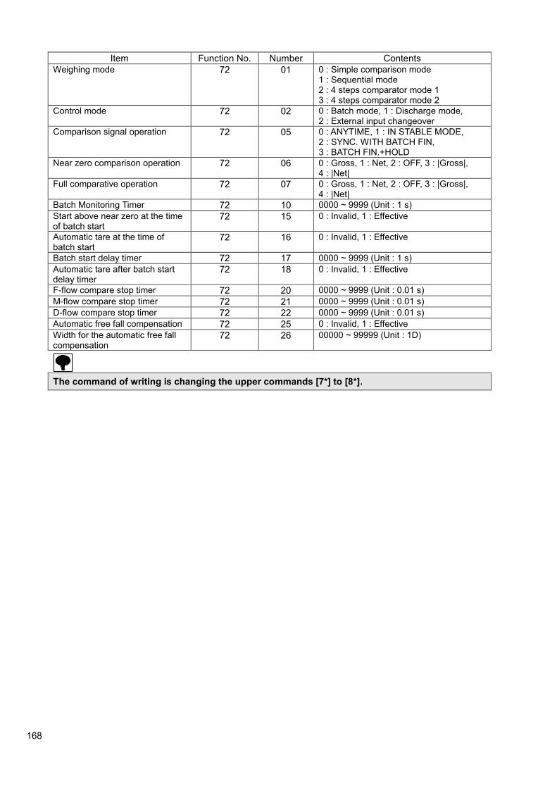
168
Item Function No. Number Contents
Weighing mode 72 01 0 : Simple comparison mode 1 : Sequential mode 2 : 4 steps comparator mode 1 3 : 4 steps comparator mode 2
Control mode 72 02 0 : Batch mode, 1 : Discharge mode, 2 : External input changeover
Comparison signal operation 72 05 0 : ANYTIME, 1 : IN STABLE MODE, 2 : SYNC. WITH BATCH FIN, 3 : BATCH FIN.+HOLD
Near zero comparison operation 72 06 0 : Gross, 1 : Net, 2 : OFF, 3 : |Gross|, 4 : |Net|
Full comparative operation 72 07 0 : Gross, 1 : Net, 2 : OFF, 3 : |Gross|, 4 : |Net|
Batch Monitoring Timer 72 10 0000 ~ 9999 (Unit : 1 s)
Start above near zero at the time of batch start
72 15 0 : Invalid, 1 : Effective
Automatic tare at the time of batch start
72 16 0 : Invalid, 1 : Effective
Batch start delay timer 72 17 0000 ~ 9999 (Unit : 1 s)
Automatic tare after batch start delay timer
72 18 0 : Invalid, 1 : Effective
F-flow compare stop timer 72 20 0000 ~ 9999 (Unit : 0.01 s)
M-flow compare stop timer 72 21 0000 ~ 9999 (Unit : 0.01 s)
D-flow compare stop timer 72 22 0000 ~ 9999 (Unit : 0.01 s)
Automatic free fall compensation 72 25 0 : Invalid, 1 : Effective
Width for the automatic free fall compensation
72 26 00000 ~ 99999 (Unit : 1D)
The command of writing is changing the upper commands [7*] to [8*].

169
Item Function No. Number Contents
Judge condition 72 30 0 : Timer is up 1 : Stable and timer is up 2 : Stable or timer is up
Waiting time for judge 72 31 0000 ~ 9999 (Unit : 0.01 s)
Maximum time of compensation flow
72 35 000 ~ 255 (Unit : 1 time)
Judge condition after compensation flow
72 36 0 : Timer is up 1 : Stable and timer is up 2 : Stable or timer is up
Compensation flow time 72 37 0000 ~ 9999 (Unit : 0.01 s)
Waiting time for judge after compensation flow
72 38 0000 ~ 9999 (Unit : 0.01 s)
Output time for the Batch finish signal
72 40 0000 ~ 9999 (Unit : 0.01 s)
Batch finish output OFF 72 41 0 : No condition 1 : OL or unstable 2 : Near zero
Discharge start at the time batch finish
72 45 0 : Invalid, 1 : Effective
Discharge monitor timer 72 46 0000 ~ 9999 (Unit : 0.01 s)
Discharge gate close delay time 72 47 0000 ~ 9999 (Unit : 0.01 s)
Discharge finish output time 72 48 0000 ~ 9999 (Unit : 0.01 s)
Tare cancellation at the time of discharge finish
72 49 0 : Invalid, 1 : Effective
The command of writing is changing the upper commands [7*] to [8*].

170
(13) Communication error processing
This unit returns the error command to the host side when the communication error or the execution error occurs.
2 4 6 8
@ 0 0 E R 0 1 Terminator
Error command No.
Contents Remarks
01 Non-executable error In the calibration mode, the function mode or the check mode.
02 Other errors by convenience of this unit
When the receiving command cannot be executed.
10 Parity error At the parity detection error.
11 Fleming error At the stop bit detection error.
12 Over run error At the receiving command reading error.
13 Data code and data lengthy error
When neither the received data code nor data length is corresponding.
14 No pertinent command When the receiving command is not corresponding.
20 Error display of the zero calibration
When the load cell output voltage is -2.5 mV/V or less.
21 Error display of the zero calibration
When the load cell output voltage is 2.5 mV/V or more.
22 Error display of the span calibration
When the difference of the load cell output voltage between span point and zero point is 0.0 mV/V or less.
23 Error display of the span calibration
When the load cell output voltage is 3.1 mV/V or more.
・ The error command is not replied when Address and the completion code (terminator) cannot be
detected.
・ Please consider dealing on the host side when the communication error command is returned from this instrument.
Address
00 to 31 Error command No.

171
16-3-13. Data format synchronizing with data format in Stream mode
・ The load data enters from the right.
・ The sign of [----] for minus and [++++] for plus is entered.
・ The load data performs zero suppress.
・ The decimal point adheres to a specified position when the decimal point is set with F-46 and when decimal point is specified with CF-01.
・ [OL] is appeared in the load data section at the over load.
・ The empty sections are all spaces.
(1) When the setting by function F-41 (RS-232C/422/485) or function F-48 (standard RS-485) is set as [Display interlock], [GROSS] and [NET]
Return (CSD-903 → Host)
2 4 6 8 10 12 14
@ 0 0 9 9 Terminator
2 4 6 8 10 12 14
@ 0 0 9 9 ― 1 2 3 Terminator
2 4 6 8 10 12 14
@ 0 0 9 9 + 0 . 1 2 3 Terminator
2 4 6 8 10 12 14
@ 0 0 9 9 + O L Terminator
2 4 6 8 10 12 14
@ 0 0 9 9 ― O L Terminator
(2) When the setting of function F-41 (RS-232C/422/485) or function F-48 (standard RS-485) is set as [Conditional load display data]
2 4 6 8 10 12 14 16
C1 C2 , C3 C4 , C5 C6 C7 C8 C9 C10 C11 C12 C13 C14 C15 Terminator
Header 1 Header 2 Sign Load data 8 digits Unit
C1 C2 Contents C3 C4 Contents C5 Contents C6 C7 C8 C9 C10 C11 C12 C13 C14 C15 Contents
O L Overload N T Net + Plus 1 2 3 g glam
S T Stable G S Gross - Minus 0 . 1 2 3 k g Kilo-gram
U S Unstable O L t ton
l b Pound
N Newton
k N Kilo-Newton
Command No. Sign of Load data
Load data
Header 1 Header 2 Sign Load data 8 digits Unit
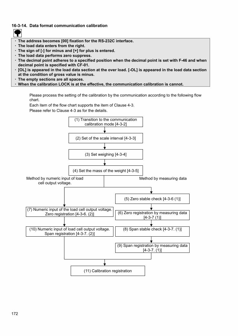
172
16-3-14. Data format communication calibration
・ The address becomes [00] fixation for the RS-232C interface.
・ The load data enters from the right.
・ The sign of [-] for minus and [+] for plus is entered.
・ The load data performs zero suppress.
・ The decimal point adheres to a specified position when the decimal point is set with F-46 and when decimal point is specified with CF-01.
・ [OL] is appeared in the load data section at the over load. [-OL] is appeared in the load data section at the condition of gross value is minus.
・ The empty sections are all spaces.
・ When the calibration LOCK is at the effective, the communication calibration is cannot.
Please process the setting of the calibration by the communication according to the following flow chart.
Each item of the flow chart supports the item of Clause 4-3.
Please refer to Clause 4-3 as for the details.
(1) Transition to the communication calibration mode [4-3-2]
(2) Set of the scale interval [4-3-3]
(3) Set weighing [4-3-4]
(4) Set the mass of the weight [4-3-5]
(5) Zero stable check [4-3-6 (1)]
(6) Zero registration by measuring data [4-3-7 (1)]
(8) Span stable check [4-3-7. (1)]
(9) Span registration by measuring data [4-3-7. (1)]
(7) Numeric input of the load cell output voltage. Zero registration [4-3-6. (2)]
(10) Numeric input of load cell output voltage. Span registration [4-3-7. (2)]
(11) Calibration registration
Method by numeric input of load cell output voltage.
Method by measuring data
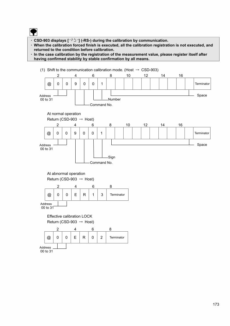
173
・ CSD-903 displays [ ] (-RS-) during the calibration by communication.
・ When the calibration forced finish is executed, all the calibration registration is not executed, and returned to the condition before calibration.
・ In the case calibration by the registration of the measurement value, please register itself after having confirmed stability by stable confirmation by all means.
(1) Shift to the communication calibration mode. (Host → CSD-903)
2 4 6 8 10 12 14 16
@ 0 0 9 0 0 1 Terminator
At normal operation
Return (CSD-903 → Host)
2 4 6 8 10 12 14 16
@ 0 0 9 0 0 1 Terminator
At abnormal operation
Return (CSD-903 → Host)
2 4 6 8
@ 0 0 E R 1 3 Terminator
Effective calibration LOCK
Return (CSD-903 → Host)
2 4 6 8
@ 0 0 E R 0 2 Terminator
Address
00 to 31
Command No.
Number Space
Address
00 to 31
Command No.
Sign
Space
Address
00 to 31
Address
00 to 31

174
(2) Set of the scale interval (Host → CSD-903)
2 4 6 8 10 12 14 16
@ 0 0 9 0 0 2 Terminator
At normal operation
Return (CSD-903 → Host)
2 4 6 8 10 12 14 16
@ 0 0 9 0 0 2 Terminator
At abnormal operation
Return (CSD-903 → Host)
2 4 6 8
@ 0 0 E R 1 3 Terminator
(3) Set weighing capacity (Host → CSD-903)
2 4 6 8 10 12 14 16
@ 0 0 9 0 0 3 Terminator
At normal operation
Return (CSD-903 → Host)
2 4 6 8 10 12 14 16
@ 0 0 9 0 0 3 Terminator
At abnormal operation
Return (CSD-903 → Host)
2 4 6 8
@ 0 0 E R 1 3 Terminator
Address
00 to 31
Address
00 to 31
Command No.
Number Set value
Address
00 to 31
Command No.
Number Set value
Address
00 to 31
Address
00 to 31 Number Set value
Command No.
Address
00 to 31 Number Set value
Command No.

175
(4) Set the mass of the weight. (Host → CSD-903)
2 4 6 8 10 12 14 16
@ 0 0 9 0 0 4 Terminator
At normal operation
Return (CSD-903 → Host)
2 4 6 8 10 12 14 16
@ 0 0 9 0 0 4 Terminator
At abnormal operation
Return (CSD-903 → Host)
2 4 6 8
@ 0 0 E R 1 3 Terminator
(5) Zero point stable check (Host → CSD-903)
2 4 6 8 10 12 14 16
@ 0 0 9 0 0 6 Terminator
Stable
Return (CSD-903 → Host)
2 4 6 8 10 12 14 16
@ 0 0 9 0 0 6 1 Terminator
Unstable
Return (CSD-903 → Host)
2 4 6 8 10 12 14 16
@ 0 0 9 0 0 6 0 Terminator
Address
00 to 31
Command No.
Number Set value
Address
00 to 31
Address
00 to 31
Command No.
Number
Address
00 to 31
Command No.
Number
Address
00 to 31
Command No.
Number
Address
00 to 31
Command No.
Number Set value

176
(6) Zero point registration by the measuring data (Host → CSD-903)
2 4 6 8 10 12 14 16
@ 0 0 9 0 0 7 Terminator
At normal operation
Return (CSD-903 → Host
2 4 6 8 10 12 14 16
@ 0 0 9 0 0 7 Terminator
At abnormal operation
Return (CSD-903 → Host)
2 4 6 8
@ 0 0 E R 2 0 Terminator
2 4 6 8
@ 0 0 E R 2 1 Terminator
Address
00 to 31
Command No.
Number
Address
00 to 31
Command No.
Number
Address
00 to 31
Address
00 to 31

177
(7) Numeric input of the load cell output voltage zero point registration. (Host → CSD-903)
1) Input of setting for the forth decimal point digit.
2 4 6 8 10 12 14 16
@ 0 0 9 0 0 8 Terminator
At normal operation
Return (CSD-903 → Host)
2 4 6 8 10 12 14 16
@ 0 0 9 0 0 8 Terminator
This is the input of the forth decimal point digit.
(ex) Input data=10001 ⇒⇒⇒⇒1.0001mV/V
2) Input of setting for the fifth decimal point digit.
2 4 6 8 10 12 14 16
@ 0 0 9 0 0 9 Terminator
At normal operation
Return (CSD-903 → Host)
2 4 6 8 10 12 14 16
@ 0 0 9 0 0 9 Terminator
This is the input of the fifth decimal point digit.
(ex) Input data = 100001 ⇒⇒⇒⇒1.00001mV/V
Address
00 to 31
Command No.
Number
Set value
Sign
Address
00 to 31
Command No.
Number
Set value
Sign
Address
00 to 31
Command No.
Number
Set value
Sign
Address
00 to 31
Command No.
Number
Set value
Sign

178
At abnormal operation
Return (CSD-903 → Host)
2 4 6 8
@ 0 0 E R 2 0 Terminator
2 4 6 8
@ 0 0 E R 2 1 Terminator
・ The command that registers mV/V of five digits below the decimal point for ZERO (No.09) and SPAN
(No.12) aiming at the performance gain of the calibration is added since ROM Ver. 2.300. When you use the command that newly registers mV/V of ZERO and SPAN, please use the command that registers mV/V of five digits below the decimal point for ZERO (No.9) and SPAN (No.12)
・ When this instrument is built into the system that has already used mV/V of four digits below the decimal point for ZERO (No.08) and SPAN (No.11), you can use the command as it is. Please note the mistake of the set digit number when changing to the command of five digits below the decimal point by registering mV/V of ZERO (No.9) and SPAN (No.12).
(8) Span stable check (Host → CSD-903)
2 4 6 8 10 12 14 16
@ 0 0 9 0 0 6 Terminator
Stable
Return (CSD-903 → Host)
2 4 6 8 10 12 14 16
@ 0 0 9 0 0 6 1 Terminator
Unstable
Return (CSD-903 → Host)
2 4 6 8 10 12 14 16
@ 0 0 9 0 0 6 0 Terminator
Address
00 to 31
Address
00 to 31
Address
00 to 31
Command No.
Number
Address
00 to 31
Command No.
Number
Address
00 to 31
Command No.
Number
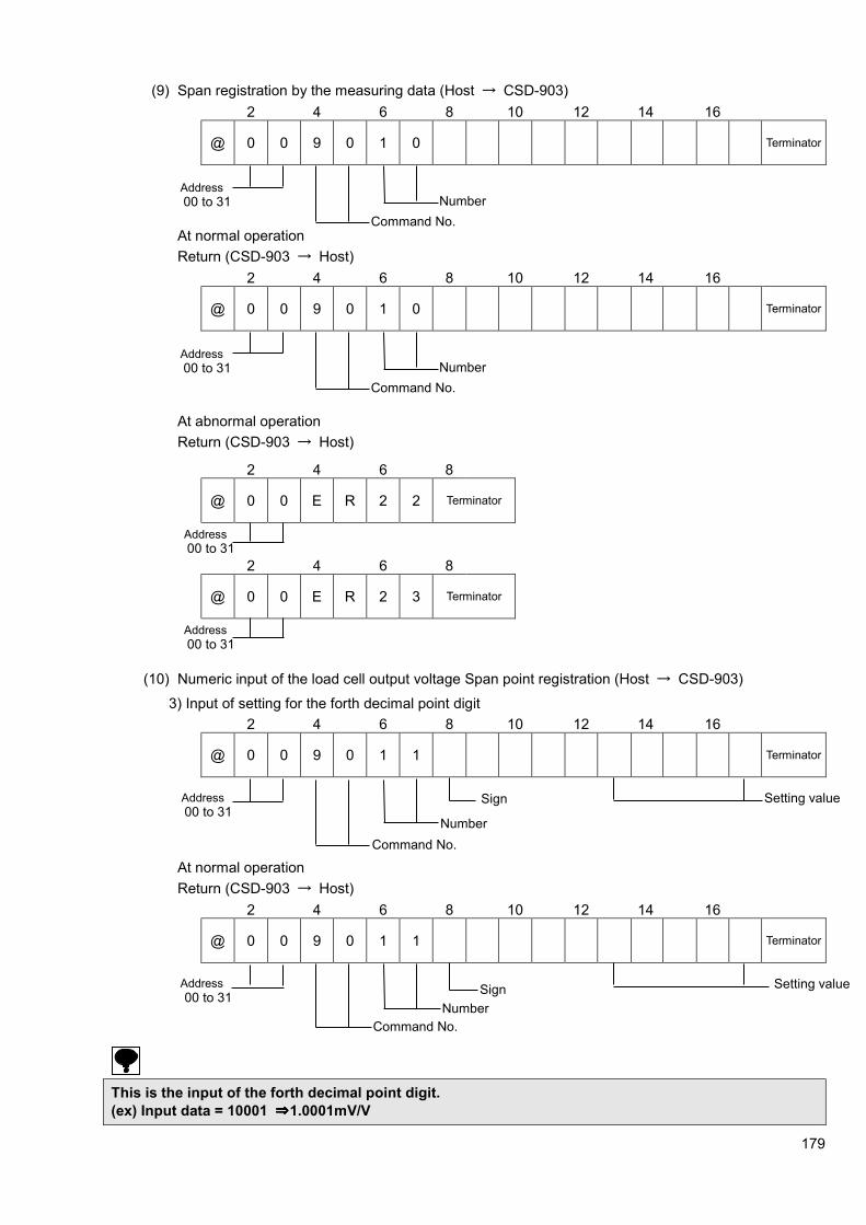
179
(9) Span registration by the measuring data (Host → CSD-903)
2 4 6 8 10 12 14 16
@ 0 0 9 0 1 0 Terminator
At normal operation
Return (CSD-903 → Host)
2 4 6 8 10 12 14 16
@ 0 0 9 0 1 0 Terminator
At abnormal operation
Return (CSD-903 → Host)
2 4 6 8
@ 0 0 E R 2 2 Terminator
2 4 6 8
@ 0 0 E R 2 3 Terminator
(10) Numeric input of the load cell output voltage Span point registration (Host → CSD-903)
3) Input of setting for the forth decimal point digit
2 4 6 8 10 12 14 16
@ 0 0 9 0 1 1 Terminator
At normal operation
Return (CSD-903 → Host)
2 4 6 8 10 12 14 16
@ 0 0 9 0 1 1 Terminator
This is the input of the forth decimal point digit.
(ex) Input data = 10001 ⇒⇒⇒⇒1.0001mV/V
Address
00 to 31
Command No.
Number
Address
00 to 31
Command No.
Number
Address
00 to 31
Address
00 to 31
Setting value Address
00 to 31
Command No.
Number
Sign
Address
00 to 31
Command No.
Number
Setting value Sign

180
4) Input of setting for the fifth decimal point digit
2 4 6 8 10 12 14 16
@ 0 0 9 0 1 2 Terminator
At normal operation
Return (CSD-903 → Host)
2 4 6 8 10 12 14 16
@ 0 0 9 0 1 2 Terminator
This is the input of the fifth decimal point digit.
(ex) Input data = 100001 ⇒⇒⇒⇒1.00001mV/V
At abnormal operation
Return (CSD-903 → Host)
2 4 6 8
@ 0 0 E R 2 2 Terminator
2 4 6 8
@ 0 0 E R 2 3 Terminator
・ The command that registers mV/V of five digits below the decimal point for ZERO (No.09) and SPAN
(No.12) aiming at the performance gain of the calibration is added since ROM Ver. 2.300. When you use the command that newly registers mV/V of ZERO and SPAN, please use the command that registers mV/V of five digits below the decimal point for ZERO (No.9) and SPAN (No.12)
・ When this instrument is built into the system that has already used mV/V of four digits below the decimal point for ZERO (No.08) and SPAN (No.11), you can use the command as it is. Please note the mistake of the set digit number when changing to the command of five digits below the decimal point by registering mV/V of ZERO (No.9) and SPAN (No.12).
Address
00 to 31
Address
00 to 31
Address
00 to 31
Command No.
Number
Setting value Sign
Address
00 to 31
Command No.
Number
Setting value Sign
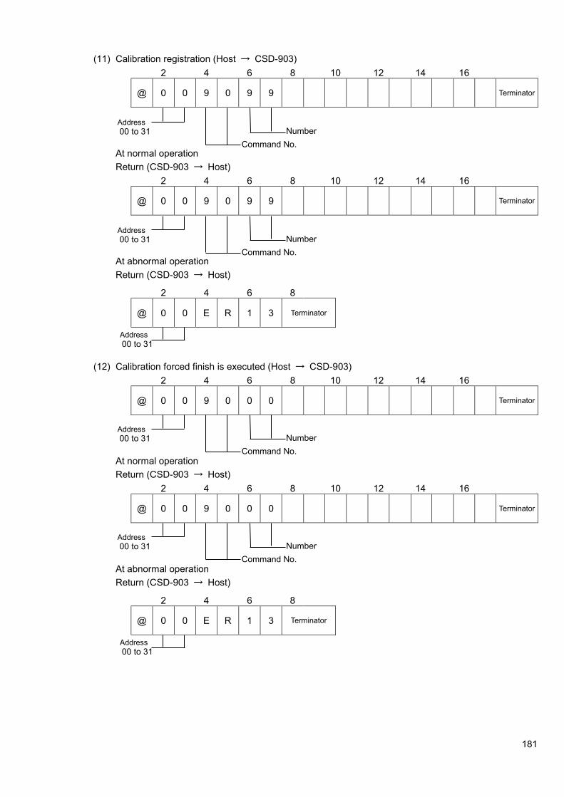
181
(11) Calibration registration (Host → CSD-903)
2 4 6 8 10 12 14 16
@ 0 0 9 0 9 9 Terminator
At normal operation
Return (CSD-903 → Host)
2 4 6 8 10 12 14 16
@ 0 0 9 0 9 9 Terminator
At abnormal operation
Return (CSD-903 → Host)
2 4 6 8
@ 0 0 E R 1 3 Terminator
(12) Calibration forced finish is executed (Host → CSD-903)
2 4 6 8 10 12 14 16
@ 0 0 9 0 0 0 Terminator
At normal operation
Return (CSD-903 → Host)
2 4 6 8 10 12 14 16
@ 0 0 9 0 0 0 Terminator
At abnormal operation
Return (CSD-903 → Host)
2 4 6 8
@ 0 0 E R 1 3 Terminator
Address
00 to 31
Command No.
Number
Address
00 to 31
Command No.
Number
Address
00 to 31
Address
00 to 31
Command No.
Number
Address
00 to 31
Command No.
Number
Address
00 to 31

182
17. Trouble shooting When abnormal point(s) is/are found during the operation of the instrument, check by the following procedures.
However, when you can't find applicable item nor solve the symptom of trouble even after you have taken some measures, contact with our.
17-1. Execute trouble shooting
Inform us about the contents of
failure and situation at site in details

183
Inform us about the contents of
failure and situation at site in details

184
1
(1) Remove the connecting cable for strain gage applied transducer from the terminal board. (2) Measure the voltage between A-C after short-circuiting A-F and C-G of terminal board. * Set the connecting range to DC-V for the measuring instrument such as tester and so on.
The voltage between
A and C is stable in the set value
of excitation voltage.
(1) Connect the connecting cable for strain gage applied transducer to the terminal board again (2) Confirm the output voltage of the load cell according to the paragraph 12-6.
Monitoring display
exceeds the range from -3.1
mV/V to 3.1 mV/V
Re-calibrate according to the procedures in Chapter 4.
Same condition
Start measurement
Contact with us.
No
Shorten between B and D in the connector
Yes
Monitoring display
exceeds the range from -3.1
mV/V to 3.1 mV/V
Yes
Yes Following causes can be considered. (1) The input of strain gage applied transducer exceeds the range from -3.1 mV/V to 3.1 mV/V. (2) The strain gage applied transducer has broken due to overload and so on. (3) The signal wire of the strain gage applied transducer has been cut off.
No
Inform us about the contents of failure and situation at site in details
Yes
No
No

185
2
(1) Remove the connecting cable for strain gage applied transducer from the terminal. (2) Measure the voltage between A-C after short-circuiting A-F and C-G of terminal board. * Set the connecting range to DC-V for the measuring instrument such as tester and so on.
The voltage between
A and C is stable in the set value of
excitation voltage.
(1) Shorten the B, D and C in the connector. (2) Confirm the output voltage of the load cell according to the paragraph 12-6.
The display stabilizes
with the optional value
(1) Please confirm the wiring status according to the contents of paragraph 2. (2) Please confirm whether there may have the influence from the noise
source such as inverters.
Same condition
Start measurement
No
No
No
Inform us about the contents of failure and situation at site in details.
Inform us about the contents of failure and situation at site in details. Yes
Yes
Yes

186
Is set value for each BRAND and RECIPE is
suitable?
Is the intended operation made?
Is the setting of I/O correct?
Set the I/O correct referring to 8-13.
Set the measurement comparison value referring to 9-2.
Measurement operation check
Set the operation of measurement referring to 9-3 from 9-9.
Inform us about the contents of failure and situation in details.
Yes
Yes
Yes
No
No
No

187
Standard communication check
Standard RS-485 and Modbus are wrong.
Inform Minebea about the contents of failure and situation in details at site .
No.
Yes The
communication of serial interface is wrong.
To serial interface communication check
No.
Yes
No. Correct connecting?
Connect surely with the external equipment by referring to the 14-4.
The address No. is correctly set.
Yes
No.
The communication protocol is correctly set.
Yes
Set the flow control to “YES” from “NONE”.
No. Setting of
command/data is correct.
Yes Set the address No. correctly by referring to 14-3-3.
No.
The host specifies the flow control.
Yes
Set it correctly according to the specifications for host.
No.
Yes
Make use of correct command/data by referring to 16-3-12.
Inform Minebea about the contents of failure and situation in details.
Yes
No.
There is a possibility not to be able to respond in case of the host's response is slow. Enlarge the response delay time of the instrument.
No. The interval from the command receipt of host to send should be set as 1ms or more.
The interval from the command receipt of host to
send is 1 ms or more.
Is it appropriate setting for the response delay time
to the response of host?
Yes
Inform us about the contents of failure and situation at site in details
Inform us about the contents of failure and situation at site in details

188
Inform us about the contents of failure
and situation at site in details

189
The external control I/O is set.
External control input is wrong.
Connecting wires are corrected?
Connect surely according to 2-3.
External control I/O check
Yes
No.
No.
Set the external control I/O.
Yes
No.
Set the pulse input value 50ms or more.
Inform Minebea about the contents of failure and situation in details.
Yes
No.
Yes
Yes
Inform Minebea about the contents of failure and situation in details.
Set the pulse input value 50ms or more.
No.
50 ms or more of input signal is set for the
pulse input.
50 ms or more of input signal for the item of
Level input.
Inform us about the contents of failure and situation at site in details
Inform us about the contents of failure and situation at site in details

190
Inform us about the contents of failure and situation at site in details

191
To the
Voltage output load resistance is 5 kΩ or more. Current output load resistance is 510 Ω or less.
Make the load resistance suitable for the specifications.
Analog output check
Correct connecting?
Connect wires surely by referring to the “16-1-3.
Confirm the setting concerning the analog output.
Correctly set.
Set correctly according to the “16-1. Analog output”
No.
No.
No.
Yes
Yes
Yes
Inform Minebea about the contents of failure and situation in details.
Inform us about the contents of failure and situation at site in details

192
BCD output check
Correct connecting? No.
Yes
No.
Yes
No.
Yes
No.
Yes The BCD
output does not change.
The intended value is not outputted.
Except for the BCD are outputted.
Connect wires surely with an external equipment according to the 16-2-7.
Make the HOLD input opened.
Select the target of BCD output by referring to the “16-2-3.
Match the setting concerning the BCD output to the specification of an external connected equipment according to 16-2-4.
Inform Minebea about the contents of failure and situation in details.
Inform us about the contents of failure and situation at site in details
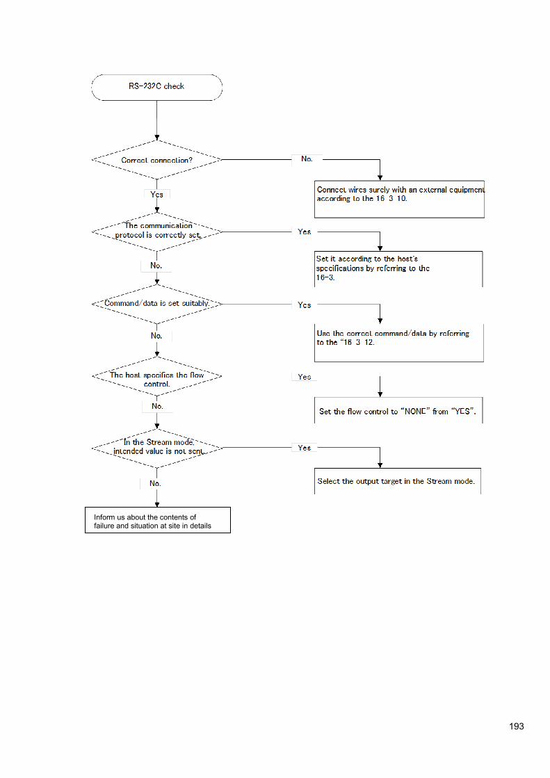
193
Inform us about the contents of failure and situation at site in details

194
RS-422 check
No. Correct connecting?
Yes
Connect wires surely with an external equipment according to the 16-3-11.
No.
The address number is correctly set.
Yes
Make the change of RS-422/485 correctly.
No.
The communication protocol is correctly set.
Yes
Set the flow control to “NONE” from “YES”.
No. Command/data is correctly set.
Yes Set the address number correctly according to the 16-3-6.
No.
The host specifies the flow control.
Yes
Please match the setting of function correctly to the specification of the host according.
No.
The change of RS-422/485 is properly set.
Yes
Use the correct command/data by referring to the 16-3-12.
. Inform Minebea about the contents of failure and situation in details.
Inform us about the contents of failure and situation at site in details

195
RS-485 check
No. Correct connecting?
Yes
Connect wires surely with an external equipment according to the 16-3-11.
No.
The address number is correctly set.
Yes
Switch RS-422/485 correctly.
No.
The communication protocol is correctly set.
Yes
Set the flow control to “NONE” from “YES”.
No. Command/data is set properly.
Yes Set the address number correctly according to the 16-3-6.
No.
The host specifies the flow control.
Yes
Set according to the specifications of host.
No.
The change of RS-422/485 is correctly set.
Yes
Use the correct command/data by referring to the 16-3-12.
Inform Minebea about the contents of failure and situation in details.
Yes
No.
There is a possibility not to be able to respond because the host's response is slow. Enlarge the response delay time of the instrument.
No. Set the interval from the command receipt of host to send is 1 ms or more.
The interval from the command receipt of host to
send is 1 ms or more.
Is it appropriate setting for the response delay time to the response of host?
Yes
Inform us about the contents of failure and situation at site in details

196
18. Specifications 18-1. Analog specifications
Bridge power supply DC10 V±0.5 V (5 V, 2.5 V) within 180 mA, with remote sensing
Applicable transducers Up to 6 pieces of strain gage applied transducers (350 ohm) can be connectable.
Input sensitivity 0.2 μ V/d or more (d= minimum scale)
Input range -3.1 mV/V ~ 3.1 mV/V
Zero adjustment range ±2.5 mV/V
Non linearity 0.01 %F.S.
Influence due to temperature change
Zero point ±0.2μ V/℃ (When the calibration is made at 0.2 μ V/d or more of
the input sensitivity.)
Sensitivity ±0.0015 %F.S./℃(Calibrated at 0.2 μ V/d of input sensitivity or
more. )
Input noise ±0.2 μ Vp-p or less. (When the calibration is made at 0.2 μ V/d or
more of the input sensitivity.)
Analog filter Approx. 4 Hz (Approx. 2, 6, 8, and 10 Hz can be changed.)
A/D sampling 200 times/s (Changeable to 20 times/s.)
A/D internal resolution 24 bits
18-2. Specifications for digital Load display
Display range The accumulation value display range is from –9 999 999 9999 to 9 999 999 999, and accumulation times is from 0 to 999 999.
Display increment 1 (Changeable to 2, 5, 10, 20 or 50)
Display unit 7-segment green colored fluorescent display tube with character’s height 11.55 mm, 7 digits
Over display [-OL] display at minus over, [OL] display at plus over
AD value over display [-OVF] display at minus over, [OVF] display at plus over
Sub display
Display range Accumulation total display -19 999 999 ~ 99 999 999, Accumulation times 0 ~ 999 999.
Display unit 7-segment green colored fluorescent display tube with character’s height 5 mm , 18 digits
Display details OFF (Changeable: Brand / Accumulation times / Accumulation value, Brand / Accumulation times / Last accumulated data, brand / Last accumulated data / Accumulation value, Brand / Last accumulated data / OK, Brand / Accumulation times / OK, Brand / OK / Accumulation value, Brand / Near zero / Full, OK / Over / Under, Brand / OK / Free fall, Brand / S1 / S2, brand / S1 / S3, brand / S1 /S4, brand /S2 / S3, Brand / S2 / S4, brand / S3 / S4, brand / OK, brand / Over / Under, Brand / Accumulation times, Brand / Accumulation value or Brand / Last accumulated data)
Condition display STABLE, PRE.TARE, TARE, GROSS, NET, CZ, HOLD, ERROR, Z-BAND OK/S0, F.FLOW/S1, M.FLOW/S2, D.FLOW/S3, OVER/S4, UNDER, FULL
Display rate 4 times/s (Changeable: 20 times/s)
Decimal point display Changeable: No display, 101, 102 , 103 and 104.
Unit display Changeable: No display, g, kg, t , N, kN or lb
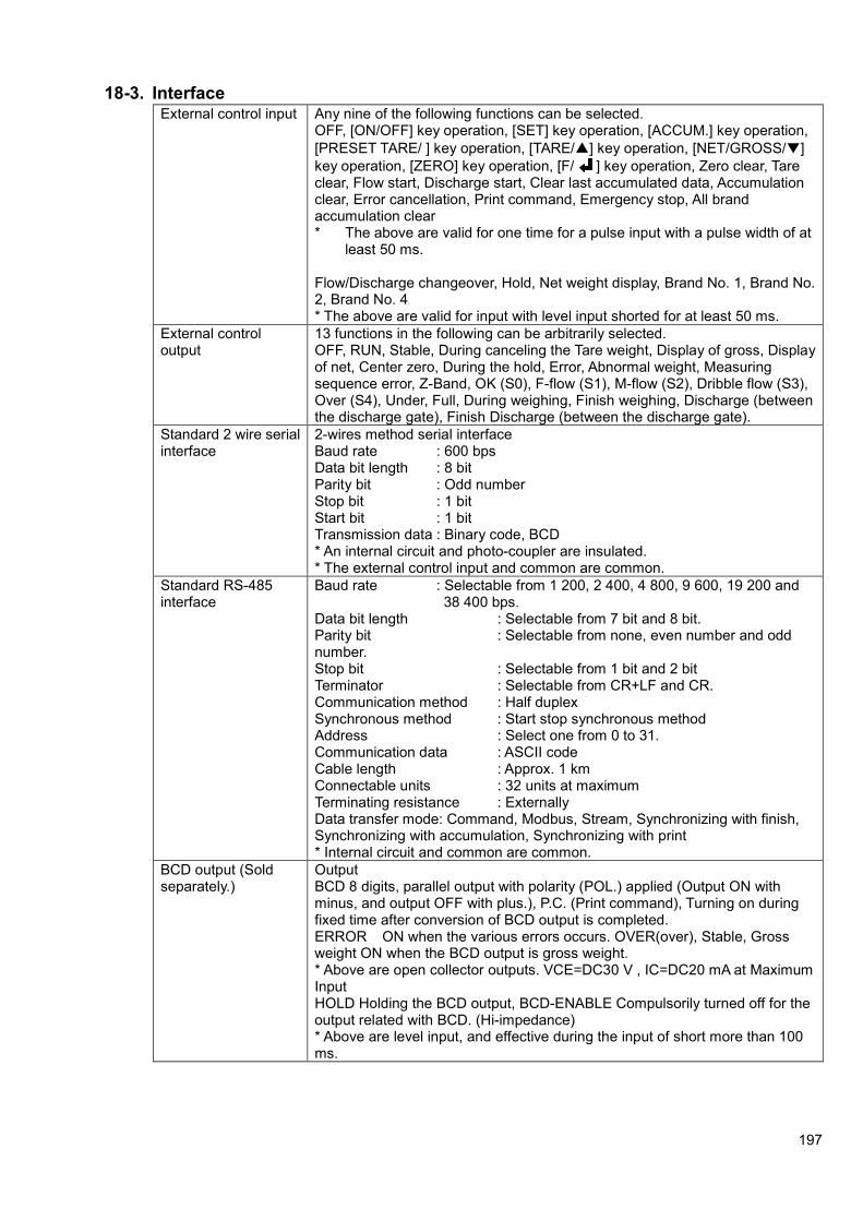
197
18-3. Interface External control input Any nine of the following functions can be selected.
OFF, [ON/OFF] key operation, [SET] key operation, [ACCUM.] key operation,
[PRESET TARE/ ] key operation, [TARE/▲] key operation, [NET/GROSS/▼]
key operation, [ZERO] key operation, [F/ ] key operation, Zero clear, Tare clear, Flow start, Discharge start, Clear last accumulated data, Accumulation clear, Error cancellation, Print command, Emergency stop, All brand accumulation clear * The above are valid for one time for a pulse input with a pulse width of at least 50 ms. Flow/Discharge changeover, Hold, Net weight display, Brand No. 1, Brand No. 2, Brand No. 4 * The above are valid for input with level input shorted for at least 50 ms.
External control output
13 functions in the following can be arbitrarily selected. OFF, RUN, Stable, During canceling the Tare weight, Display of gross, Display of net, Center zero, During the hold, Error, Abnormal weight, Measuring sequence error, Z-Band, OK (S0), F-flow (S1), M-flow (S2), Dribble flow (S3), Over (S4), Under, Full, During weighing, Finish weighing, Discharge (between the discharge gate), Finish Discharge (between the discharge gate).
Standard 2 wire serial interface
2-wires method serial interface Baud rate : 600 bps Data bit length : 8 bit Parity bit : Odd number Stop bit : 1 bit Start bit : 1 bit Transmission data : Binary code, BCD * An internal circuit and photo-coupler are insulated. * The external control input and common are common.
Standard RS-485 interface
Baud rate : Selectable from 1 200, 2 400, 4 800, 9 600, 19 200 and 38 400 bps. Data bit length : Selectable from 7 bit and 8 bit. Parity bit : Selectable from none, even number and odd number. Stop bit : Selectable from 1 bit and 2 bit Terminator : Selectable from CR+LF and CR. Communication method : Half duplex Synchronous method : Start stop synchronous method Address : Select one from 0 to 31. Communication data : ASCII code Cable length : Approx. 1 km Connectable units : 32 units at maximum Terminating resistance : Externally Data transfer mode: Command, Modbus, Stream, Synchronizing with finish, Synchronizing with accumulation, Synchronizing with print * Internal circuit and common are common.
BCD output (Sold separately.)
Output BCD 8 digits, parallel output with polarity (POL.) applied (Output ON with minus, and output OFF with plus.), P.C. (Print command), Turning on during fixed time after conversion of BCD output is completed. ERROR ON when the various errors occurs. OVER(over), Stable, Gross weight ON when the BCD output is gross weight. * Above are open collector outputs. VCE=DC30 V , IC=DC20 mA at Maximum Input HOLD Holding the BCD output, BCD-ENABLE Compulsorily turned off for the output related with BCD. (Hi-impedance) * Above are level input, and effective during the input of short more than 100 ms.

198
RS-232C (Sold separately.)
Baud rate : Selectable from 1 200, 2 400, 4 800, 9 600, 19 200 and 38 400 bps. Data bit length : Selectable from 7 bit and 8 bit Parity bit : Selectable from None, Even and Odd number. Stop bit : Selectable from 1 bit and 2 bit Terminator : Selectable from CR + LF and CR Communication method : Half duplex Synchronous method : Start-stop synchronous method Communication data : ASCII code
RS-422/485 (Sold separately.)
Baud rate : Selectable from 1 200, 2 400, 4 800, 9 600, 19 200 and 38 400 bps. Data bit length : Selectable from 7 bit and 8 bit Parity bit : Selectable from None, Even and Odd number. Stop bit : Selectable from 1 bit and 2 bit
Terminator : Selectable from CR+LF and CR
Communication method : Half duplex Synchronous method : Start-stop synchronous method Address : Selectable one from 0 to 31. Transmission data : ASCII code Cable length : Approx. 1 km
Connectable units : 32 units at the maximum (RS-422:10 units)
Terminal resistance : Internal (Selects the presence by connection of terminal board.) Input/output monitor with LED Changeover the RS-422/485: Set by function.
Current output (Sold separately.)
Output : DC4 mA ~ 20 mA Load resistance : 510 ohm or less Resoulution : Approx.1/12 000 or more Non-linearity : 0.02 %F.S.
Over range : Approx.DC2.4 mA at [-OL] display and
Approx.DC21.6 mA at [OL] display. Output times : 4 times/s, 20 times/s (Synchronous to display times). * An internal circuit and photo-coupler are insulated. Effect due to temperature
Zero point : ±0.005 % F.S./ ℃
Sensitivity : ±0.01 % F.S./ ℃
Voltage output (Sold separately.)
Output : DC0 V ~ 10 V Load resistance : 5 k-ohm or more Resoulution : Approx.1/12 000 or more Non-linearity : 0.02 %F.S.
Over range : Approx.DC -1 V at [-OL display and
Approx.DC11 V at [OL] display Output times : 4 times/s, 20 times/s (Synchronous to display times) * An internal circuit and photo-coupler are insulated. Effect due to temperature
Zero point : ±0.015 % F.S./ ℃
Sensitivity : ±0.015 % F.S./ ℃

199
18-4. General specifications Operating temperature range
Temperature -10 ℃ ~ 50 ℃
※The temperature span of JIS B 7611-2 conformity is -10 ℃ ~
40 ℃
Humidity 85 %RH or less (Non condensing.)
Storage temperature range -20 ℃ ~ 60 ℃
Power supply Power-supply voltage
AC100 V ~ AC240 V (Permissible variable range AC85 V ~ AC264 V)
Power supply frequency
50/60 Hz
Power consumption
Approx. 10 VA (without options, at AC100 V) Approx. 18 VA (with options at AC100 V)
Outline dimensions (W×H×D) 144 mm(W)× 72 mm(H)× (less than)146.7 mm(D) (excludes protruding parts)
Weight Approx.1.0 kg (without options)
18-5. Standard specifications at the time of shipment
Bridge excitation DC10 V
Span adjustment 10 000 displays with the input of 0.3 mV/V.
Scale interval 1
18-6. Accessories
Instruction Manual 1 piece
Time lag Fuse(2.5A) 1 piece
I/O connector for external control
1 piece (connector: FCN-361J024-AU, connector cover: FCN360C024-B)
Connector for standard communication
1 piece (plug :XW4B-06B1-H1)
Short bar, between A-F and C-G
2 pieces
Panel mount gasket 1 piece
Connector for BCD output 1 piece (Attached only when optional BCD output is installed.)
Instruction manual for optional CC-LINK
1 piece (Attached only when optional CC-LINK interface is installed.)
CC-LINK connector 1 piece (Attached only when optional CC-LINK interface is installed.)

200
19. Error display 19-1. Error Load display
Display blinking for about 2 seconds when C function or function is set and no number in the list is selected.
Display blinking for about 2 seconds when the calibration is executed, and [Display of the weighing capacity (DISP)] < [Set of mass weight value (LOAD)] is set.
A/D conversion error. Please contact with us.
EEPROM writing error. Please contact with us
EEPROM reading error. Please contact with us.
Display blinking for about 2 seconds when the calibration is executed and output of the load cell and numeric input is –2.5 mV/V or less and exceeding the zero adjustment range at the minus side.
Display blinking for about 2 seconds when the calibration is executed, and output of the load cell and numeric input is 2.5 mV/V or more and exceeding the zero adjustment range at the plus side.
Display blinking for about 2 seconds when the calibration is executed and output of the load cell and numeric input is less than 0 mV/V and not reaching within the span adjustment range.
Display blinking for about 2 seconds when the calibration is executed and output of the load cell and numeric input is more than 3.1 mV/V and exceeding the span adjustment range.
Display blinking for about 2 seconds when the digital linearization compensation is executed and the load cell output is low.
Display blinking for about 2 seconds when the digital linearization compensation is executed and the load cell output is high.
(When C function CF-15 [Power on zero operation] is effective.) Displayed when the power is turned on or the display is ON with the
condition of the load cell output exceeding ±10 % of the weighing
capacity.
If the key is pressed with [ ] displayed, it compulsorily becomes a load value display.
Light on when the load display is exceeding [(+Weighing capacity) + 9D], or exceeding [+110 % of weighing capacity]. (by the setting of C function CF-03)
Light on when the load display is exceeding [(-Weighing capacity)-9D], or exceeding [-110 % of the weighing capacity], or exceeding [- 20D] (by the setting of C function CF-03)
The input to A/D converter is plus over.
The input to A/D converter is minus over.
All lights Display blinking when the result of accumulated value or the accumulated count is exceeding the display range.
Battery LO error. Please contact us.
Damage on backed up data. Please contact us.

201
19-2. Error sub display Error code Contents Measures
In case of execute ZERO out of range of zero
Check the range of zero is appropriate.
In case of execute TARE out of range of tare.
Execute the TARE within the range of tare.
When the accumulated value and the accumulated count exceeding the display range results.
As the accumulating condition display blinks, please execute to clear the accumulated and count.
Error display at sub display has been blinking, as long as sequence error is not release.
Press the key to release sequence error.
20. Display of sequence error Error code Error
No. Contents Measures
1 Stop compulsorily by inputting the temporary stop while weighing
Execute the restart after checking the source of the temporary stop.
3 When the load value is under even if the supplementary flow is executed.
Execute the restart after changing the supplementary flow time and numbers.
4 When there is contradiction in the amount of the comparison value.
Solve the contradiction of amount after checking the setting value.
5 When the batching time exceeds the limited time.
Check the blocking at the batching gate.
6 When the discharging time exceed the limited time.
Check the blocking at the discharging gate.
7 When the gross value is smaller than the final value in discharge control.
Add the BRAND.
8 When the net value > (final value – free fall) in the start
Remove the contents in the container.
9 When the measurement begins in the condition that START ABOVE Near zero is [VALID], the container is not put on the measuring section.
Check that whether the container is put.
Sequence error display has been blinking at sub display, as long as sequence error is not release.
Press the key to release sequence error.

202
21. Warranty 21-1. Warranty
The instrument is covered by a warranty for a period of one year from the date of delivery.
As for repairs and/or after service is required during the period of warranty, contact with us sales office or sales agent from which you have purchased.
21-2. Repair
Before asking repairs, check once again that the connection, setting and adjustment for the instrument have finished properly.
Especially, check whether the connections of strain gage applied transducers are disconnected or cut off.
As a result of checking, still there may have some defects in the instrument, contact with our sales office or sales agency from which you have purchased.
22. Lifetime of used parts The parts used in the instrument will have lifetime. It may differ depending to application method and environmental conditions, the rough standard of lifetime of each shall be as follows:
Name of Parts Application Rough standard of lifetime
Display module Display Approx. 45000 hours (Environmental temperature : 50℃)
EEPROM Record of set data Write to EEPROM. Approx.1 000 000 times.
Electrolytic capacitor For smoothing
switching power supply
Approx.10 years(Environmental temperature : 20℃)
Battery Back up of RAM Approx.10 years(Environmental temperature : 20℃)
22-1. Display module
When using CSD-903 at the ambient temperature of approx. 50℃, the display will flicker is about
45,000 hours, and the phenomenon of the luminance’s decreasing.
22-2. EEPROM
When writing is made to EEPROM more than the time of lifetime, you can’t write to the data any more, so exchange shall be required.
22-3. Electrolytic capacitor
It may be influenced largely by some applied conditions such as environmental temperature and so on.
22-4. Battery
It may be influenced largely by some applied condition such as environmental temperature and so
on, but the lifetime shall be for approx. 10 years in room temperature at 20 ℃.

203
23. Exchange of fuses 23-1. Exchange procedure of fuse
Warning
When installation method for the fuse is wrong and/or capacity of installed fuse is inadequate, it causes an unexpected faulty of the instrument.
(13) Set OFF the power supply for the instrument.
(14) Remove the 6 pieces of screws on the rear panel.
(15) Draw out the contents of the instrument by holding the rear panel to the case direction slowly
(16) Replace the fuse installed on the P.C. board.
(17) After replacing the fuse, insert the rear panel into the case.
(18) Remove the 6 pieces of screws on the rear panel. Check that the rear panel and the case are attached closely.
Warning
If a rear panel has not stuck to the case, there is a possibility that the display does not light, or the key cannot be operated.
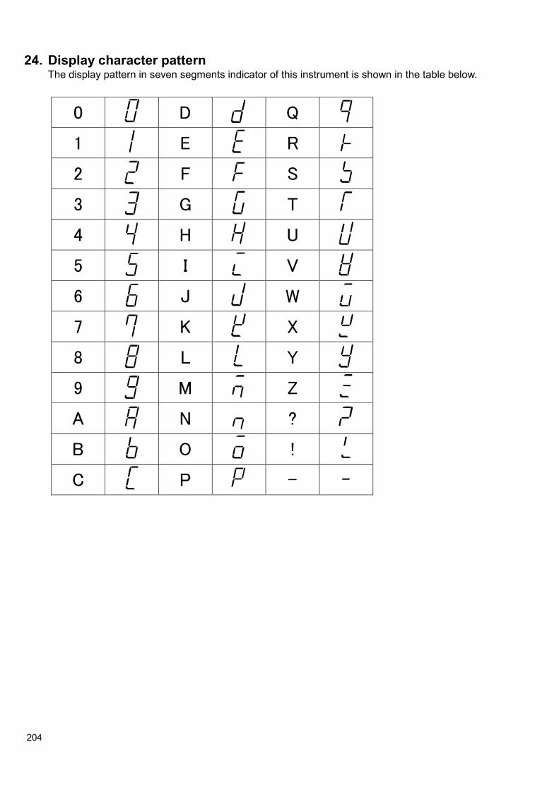
204
24. Display character pattern The display pattern in seven segments indicator of this instrument is shown in the table below.
0 D Q
1 E R
2 F S
3 G T
4 H U
5 I V
6 J W
7 K X
8 L Y
9 M Z
A N ?
B O !
C P -

205
25. Setting table for functions Make use of them in case that the customer has changed setting for the function.
Setting table for C function
Function No. Initial value Customer’s setting Function No. Initial value Customer’s setting
CF-01 0 CF-27 10
CF-02 1 CF-28 9.797
CF-03 2 CF-29 9.797
CF-05 0 CF-40 0
CF-07 0 CF-41 2
CF-08 0 CF-42 003000
CF-10 1 CF-43 3
CF-11 02 CF-44 006000
CF-12 1 CF-70 0
CF-13 00 CF-71 000000
CF-14 00 CF-72 010000
CF-15 0 CF-90 1
CF-16 0 CF-91 10000
CF-17 0 CF-92 10000
CF-18 000 CF-93 00000
CF-20 0 CF-94 03000
CF-21 0 CF-97 05
CF-25 0 CF-98 -
CF-26 10 CF-99 -
Setting table for SQ function
Function No. Initial value Customer’s setting Function No. Initial value Customer’s setting
SQF-01 1 SQF-27 0
SQF-02 0 SQF-30 0
SQF-05 2 SQF-31 0000
SQF-06 0 SQF-35 000
SQF-07 0 SQF-36 0
SQF-10 0000 SQF-37 0000
SQF-15 0 SQF-38 0000
SQF-16 0 SQF-40 0000
SQF-17 0000 SQF-41 0
SQF-18 0 SQF-45 0
SQF-20 0000 SQF-46 0000
SQF-21 0000 SQF-47 0000
SQF-22 0000 SQF-48 0000
SQF-24 0 SQF-49 0
SQF-25 0 SQF-98 -
SQF-26 00000 SQF-99 -
MEMO

206
Setting table for function
Function No. Initial value Customer’s setting Function No. Initial value Customer’s setting
F-01 16 F-48 0
F-02 1 F-49 0
F-04 0 F-50 000
F-05 092 F-51 0
F-06 020 F-52 0
F-07 05 F-55 0
F-08 0000 F-60 00
F-09 0000 F-61 00
F-10 020 F-62 00
F-11 01 F-63 00
F-15 1 F-64 00
F-16 00 F-65 00
F-17 0 F-66 00
F-18 0001 F-67 00
F-19 0 F-68 00
F-20 0000 F-70 00
F-21 0000 F-71 00
F-22 0000 F-72 00
F-23 0 F-73 00
F-24 0 F-74 00
F-25 00 F-75 00
F-26 00 F-76 00
F-30 0 F-77 00
F-31 0 F-78 00
F-32 0000 F-79 00
F-33 1 F-80 00
F-34 0 F-81 00
F-37 0 F-82 00
F-40 0 F-84 2
F-41 0 F-85 01
F-42 13020 F-86 0
F-43 00 F-87 0
F-44 0 F-90 -
F-45 01 F-91 -
F-46 0 F-99 -
F-47 0

207
Setting table of Sub-display panel (F-19)
Set value Contents Set value Contents
0 OFF 11 K Brand (1 digit) / S1 (6 digits) / S3 (6 digits)
1 A Brand (1 digit) / Accumulation times (6 digits) / Accumulation value (8 digits)
12 L Brand (1 digit) / S1 (6 digits) / S4 (6 digits)
2 B Brand (1 digit) / Accumulation times (6 digits) / Last accumulated data (6 digits)
13 M Brand (1 digit) / S2 (6 digits) / S3 (6 digits)
3 C Brand (1 digit) / Last accumulated data (6 digits) / Accumulation value (8 digits)
14 N Brand (1 digit) / S2 (6 digits) / S4 (6 digits)
4 D Brand (1 digit) / Last accumulated data (6 digits) / OK (6 digits)
15 O Brand (1 digit) / S3 (6 digits) / S4 (6 digits)
5 E Brand (1 digit) / Accumulation times (6 digits) / OK (6 digits)
16 P Brand (1 digit) / OK (6 digits)
6 F Brand (1 digit) / OK (6 digits) / Accumulation value (8 digits)
17 Q Brand (1 digit) / Over (5 digits) / Under (5 digits)
7 G Brand (1 digit) / Near zero (6 digits) / Full (6 digits)
18 R Brand (1 digit) / Accumulation times (6 digits)
8 OK (6 digits) / Over (5 digits) / Under (5 digits)
19 S Brand (1 digit) / Accumulation value (10 digits)
9 I Brand (1 digit) / OK (6 digits) / Free fall (6 digits)
20 T Brand (1 digit) / Last accumulated data (6 digits)
10 J Brand (1 digit) / S1 (6 digits) / S2 (6 digits)


●The contents of this manual may subject to change without notice.
HEAD QUARTER: MinebeaMitsumi Inc.
4106-73 Miyota, Miyota-machi, Kitasaku gun, Nagano-ken 389-0293 Japan Tel: +81-267-32-2200 Fax: +81-267-31-1350
Sensing Device Product Sales Management: 1-1-1, Katase, Fujisawa-shi, Kanagawa-ken, 251-8531 Japan Tel: +81-466-23-2681 Fax: +81-466-22-7191
Sensing Device Business Unit FUJISAWA PLANT 1-1-1, Katase, Fujisawa-shi, Kanagawa-ken, 251-8531 Japan Tel: +81-466-22-7151 Fax: +81-466-22-1701
KARUIZAWA PLANT 4106-73 Miyota, Miyota-machi, Kitasaku gun, Nagano-ken 389-0293 Japan Tel: +81-267-31-1309 Fax: +81-267-31-1353
HOMEPAGE ADDRESS http://www.minebea-mcd.com

![í ñ Z / v v ] } v o t ^ } v ( v ] P ] o Z À } o µ ] } v U ... · ks zs/ t k& y d z kekdz (frqrplf,qglfdwru $yhudjh *urvv'rphvwlf3urgxfw lq eloolrq86 *'3shu fdslwd wkrxvdqg86](https://img.pdfslide.us/doc/110x75/601c2000566cc46646789f86/-z-v-v-v-o-t-v-v-p-o-z-o-v-u-ks-zs-t-k.jpg)


![DQG QGLFDWRU 5 HSRUW Hospital Risk Management...W ] u Ç ( ( > E EKZ dKZ t Z t Z } µ v h v l v } Á v ì ì ì ì ì í í ] } v l l Z l Z u } u õ í ó í ò í ò í í î í õ](https://img.pdfslide.us/doc/110x75/5f0269aa7e708231d40426c9/dqg-qglfdwru-5-hsruw-hospital-risk-management-w-u-e-ekz-dkz-t-z.jpg)


![INSTRUCTION MANUAL - Hobbicomanuals.hobbico.com/fut/18sz-manual.pdf · 4 <introduction> 7kdqn \rx iru sxufkdvlqj d )xwded )$667hvw *+] 7 6= vhulhv gljlwdo sursruwlrqdo 5 & v\vwhp](https://img.pdfslide.us/doc/110x75/5a78d7ab7f8b9a70238d3e7e/instruction-manual-introduction-7kdqn-rx-iru-sxufkdvlqj-d-xwded-667hvw.jpg)