Embed Size (px)
Citation preview
KRB-5333
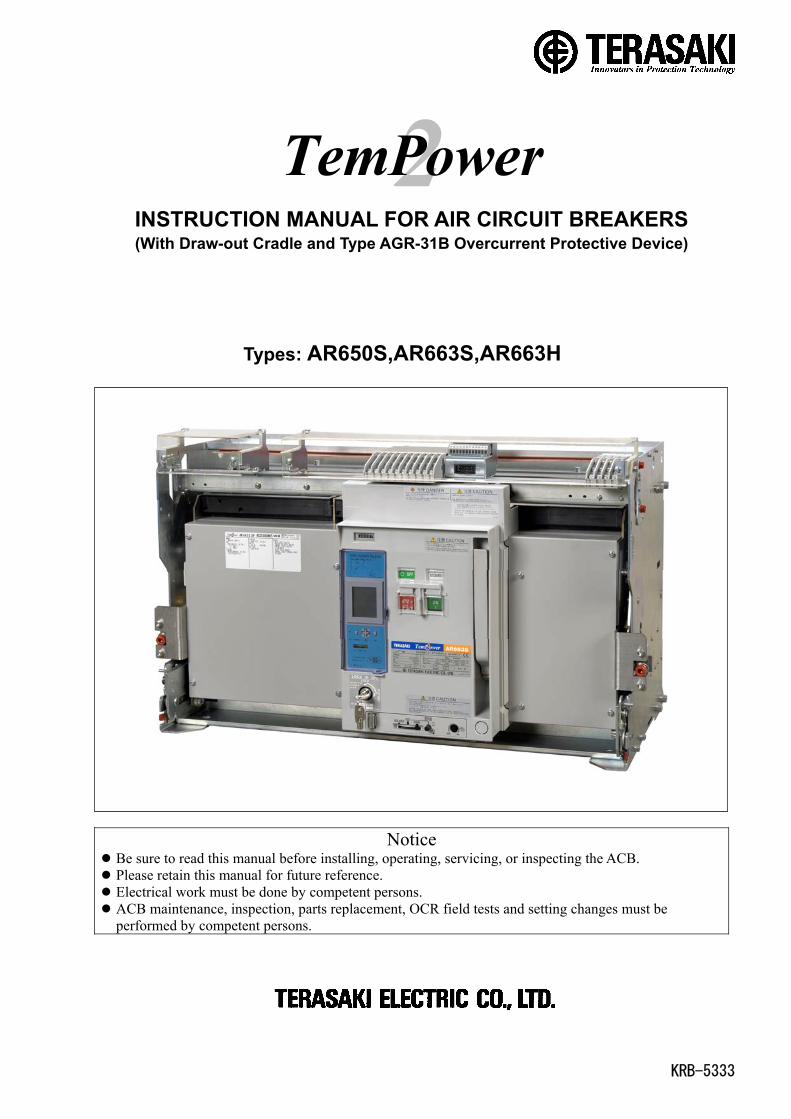
INSTRUCTION MANUAL FOR AIR CIRCUIT BREAKERS(With Draw-out Cradle and Type AGR-31B Overcurrent Protective Device)
Types: AR650S,AR663S,AR663H
Notice Be sure to read this manual before installing, operating, servicing, or inspecting the ACB. Please retain this manual for future reference. Electrical work must be done by competent persons. ACB maintenance, inspection, parts replacement, OCR field tests and setting changes must beperformed by competent persons.

KRB-5333
1. SAFETY NOTICES 5
2. RECEIVING AND HANDLING 7
2-1. Transportation Precautions 7
2-1-1. Transporting the ACB 7
2-1-2. Transporting the breaker body 8
2-1-3. Transporting the draw-out cradle 9
2-2. Storage Precautions 10
2-3. Installation Precautions 10
3. GENERAL 14
3-1. Types and Descriptions 14
3-2. Parts and Functions 17
3-3. Circuits and Ratings 21
4. OPERATION 26
4-1. Charging and Opening operation 26
4-1-1. Charging operation 26
4-1-2. Closing operation 27
4-1-3. Opening operation 27
4-1-4. Motion of trip indication and spring charge
indication switches 27
4-1-5. Motion of operation mechanisms 28
4-2. Draw-out and Insertion Operation 30
4-2-1. General 30
4-2-2. Draw-out operation 31
4-2-3. Putting the breaker body back into the draw-out
cradle 32
4-2-4. Contact status of auxiliary and position switches 34
4-3. ON-OFF Button Cover Locking Procedure 34
4-4. Lock in OFF Procedure 35
4-5. Position Lock Lever Locking Procedure 35
4-6. Breaker Fixing Bolt Securing Procedure 36
4-7. OCR Cover Locking Procedure 36
5. OVERCURRENT RELEASE (OCR) 37
5-1. Specifications 37
5-2. Characteristics 38
5-2-1. L characteristic for general feeder 38
5-2-2. R characteristic for general feeder 40
5-2-3. S characteristic for generator protection 44
5-3. How to Display Measurements and Make Settings 46
5-3-1. General 46
5-3-2. Available screens 47
5-3-3. Monitor 1 screen 48
5-3-4. Monitor 2 screen 49
5-3-5. Setup screen 51
5-3-6. Reset screen 54
5-3-7. Setting 1 screen 55
5-3-8. Setting 2 screen 57
5-3-9. Maintenance screen 60
5-4. OCR Function Check 61
5-5. Operation Indication and Indication Resetting
Procedure 63
6. MAINTENANCE, INSPECTION AND PARTS
REPLACEMENT 65
6-1. Inspection Procedures 66
6-2. Parts Replacement Procedure 69
6-2-1. Preparation 69
6-2-2. Arc chambers 72
6-2-3. Stationary arc contact and moving arc contact 73
6-2-5 Latch release coil (LRC) 75
6-2-6. Shunt trip device (SHT) 76
6-2-7. Control relay 77
6-2-8. Magnet hold trigger (MHT) 80
6-2-9. Auxiliary switches 81
7. TROUBLESHOOTING FLOWCHARTS 83
TABLE OF CONTENTS

KRB-53335
1. SAFETY NOTICESThank you for purchasing the TERASAKI AR-series Air Circuit Breaker (TemPower2).
This chapter contains important safety information.7
Be sure to carefully read these safety notices, instruction in this manual, and other documents accompanying the Air Circuit Breaker
(hereinafter referred to as the ACB) to familiarize yourself with safe and correct procedures or practices before installing, operating,
or servicing the ACB.
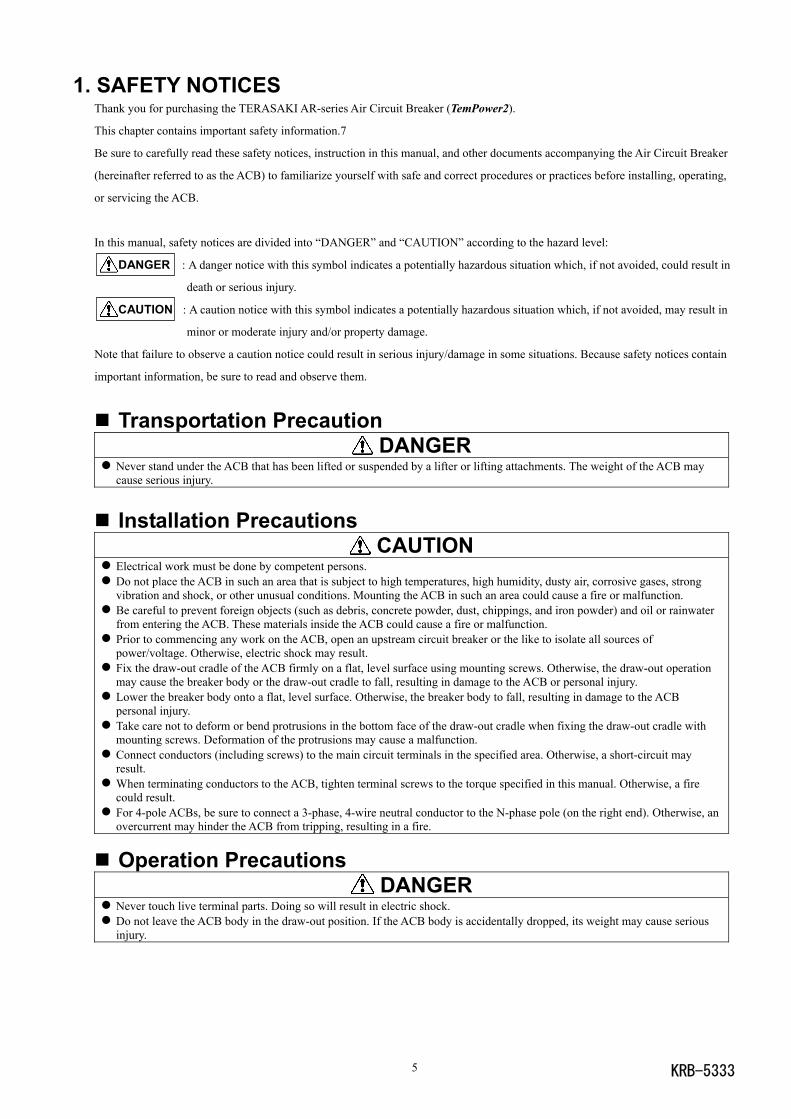
In this manual, safety notices are divided into “DANGER” and “CAUTION” according to the hazard level:
DANGER : A danger notice with this symbol indicates a potentially hazardous situation which, if not avoided, could result in
death or serious injury.
CAUTION : A caution notice with this symbol indicates a potentially hazardous situation which, if not avoided, may result in
minor or moderate injury and/or property damage.
Note that failure to observe a caution notice could result in serious injury/damage in some situations. Because safety notices contain
important information, be sure to read and observe them.
Transportation Precaution DANGER
Never stand under the ACB that has been lifted or suspended by a lifter or lifting attachments. The weight of the ACB maycause serious injury.
Installation Precautions CAUTION
Electrical work must be done by competent persons. Do not place the ACB in such an area that is subject to high temperatures, high humidity, dusty air, corrosive gases, strongvibration and shock, or other unusual conditions. Mounting the ACB in such an area could cause a fire or malfunction.
Be careful to prevent foreign objects (such as debris, concrete powder, dust, chippings, and iron powder) and oil or rainwaterfrom entering the ACB. These materials inside the ACB could cause a fire or malfunction.
Prior to commencing any work on the ACB, open an upstream circuit breaker or the like to isolate all sources ofpower/voltage. Otherwise, electric shock may result.
Fix the draw-out cradle of the ACB firmly on a flat, level surface using mounting screws. Otherwise, the draw-out operationmay cause the breaker body or the draw-out cradle to fall, resulting in damage to the ACB or personal injury.
Lower the breaker body onto a flat, level surface. Otherwise, the breaker body to fall, resulting in damage to the ACBpersonal injury.
Take care not to deform or bend protrusions in the bottom face of the draw-out cradle when fixing the draw-out cradle withmounting screws. Deformation of the protrusions may cause a malfunction.
Connect conductors (including screws) to the main circuit terminals in the specified area. Otherwise, a short-circuit mayresult.
When terminating conductors to the ACB, tighten terminal screws to the torque specified in this manual. Otherwise, a firecould result.
For 4-pole ACBs, be sure to connect a 3-phase, 4-wire neutral conductor to the N-phase pole (on the right end). Otherwise, anovercurrent may hinder the ACB from tripping, resulting in a fire.
Operation Precautions DANGER
Never touch live terminal parts. Doing so will result in electric shock. Do not leave the ACB body in the draw-out position. If the ACB body is accidentally dropped, its weight may cause seriousinjury.
KRB-5333 6
Operation Precautions (continued) CAUTION
Repeated open/close operation by the motor charging mechanism without pause should not exceed 15 times. If repeatedcontinuous open/close operation is inevitable, a pause of at least 20 minutes should be provided after the repetitions of 15times. Otherwise, a spring charging motor may be burnt out.
Do not bring your hand or face close to arc gas vent of the arc chamber while the ACB is closed. Otherwise, a burn may resultfrom high-temperature arc gas blowing out of the arc gas vent when the ACB trips open.
If the ACB trips open automatically, remove the cause of tripping operation before re-closing the ACB. Otherwise, a firecould result.
If the ACB has the breaker fixing bolts, be sure to loose the fixing bolts before draw-out operation. Otherwise, damage to theACB may result.
Make sure the draw-out cradle is secured with mounting screws before inserting or drawing out the breaker body. Otherwise,the insertion or draw-out operation may cause the breaker body or the draw-out cradle to fall, resulting in damage to the ACBor personal injury.
When retracting the draw-out rail into the draw-out cradle, be sure to push the rail end. Do not hold the hook pin, bodystopper, or body stopper shaft. Doing so may cause your fingers to be pinched, resulting in injury.
Do not forcedly turn the draw-out handle clockwise when the breaker body is in the “CONN.” position. Doing so may cause amalfunction.
If the ACB has the breaker fixing bolts, make sure the bolts on both sides are securely tightened before using the ACB.Loosened fixing bolts may cause a malfunction of the ACB, in particular when it is installed in such an area that is subject tostrong vibrations.
OCR (Overcurrent Release) Handling Precautions CAUTION
OCR field tests and setting changes must be performed by competent persons. After setting changes are made, the settings be checked with e.g., a type ANU-1 OCR checker (optional). After completion of OCR tests, be sure to return the settings to the original values. Failure to do so may cause a fire orburnout.
Before changing OCR settings, open the ACB and then lock the OFF button to prevent the ACB from being closedinadvertently.
Do not push the SET button diagonally. Doing so may cause a poor in return and malfunction.
Maintenance and Inspection Precautions CAUTION
ACB maintenance, inspection and parts replacement must be performed by competent persons. Do not touch ACB current carrying parts and ACB structural parts close to a current carrying part immediately after the ACBtrips open. Remaining heat may cause a burn.
Prior to commencing any work on the ACB, open an upstream circuit breaker or the like to isolate all sources ofpower/voltage from the main and control circuits. Otherwise, electric shock may result.
Take care to avoid adhesion of dust to main and control circuit contacts. Dust on the contacts may result in a fire. Prior to commencing maintenance, inspection, or parts replacement, make sure that the closing springs are released and theACB is open. Otherwise, unintentional open/close operation may lead to fingers or tools to be pinched by the open/closemechanism, resulting in injury.
Retighten the terminal screws periodically to the specified torque. Otherwise, a fire could result. When grinding a contact tip, be careful to prevent grinding dust from entering the breaker operating mechanism. Wipe the tipclean after grinding. Otherwise, a malfunction or fire could result.
Do not perform dielectric withstand tests under other conditions than specified. Doing so may cause a malfunction. Be sure to reinstall the arc chamber if removed. Failure to do so or incorrect installation of the arc chamber may result in a fireor burn.
When charging the closing springs or performing open/close operation of the ACB with the arc chamber, front cover and/orside covers removed during maintenance or inspection work, do not touch parts other than those required for the aboveoperation (charging handle, ON/OFF buttons, moving core and the like). Doing so may cause fingers or tools to be pinched,resulting in injury.
When replacing an auxiliary, do not damage the control wire for the auxiliary or pinch the wire between the auxiliary and thebreaker body. Doing so may cause a malfunction.
KRB-53337
Breaker body
Breaker fixing bolt
Control circuit terminalsAuxiliary switches
Control terminalblock cover
Lifting hole (ø20mm)
Arc gas barrier
Draw-out arm
*When lifting the ACB, the length of
the rope do not be beyond the range
of the angle to show in figure.
ACB Lifting attachment
Rope
2. RECEIVING AND HANDLINGUpon receipt of your ACB, check the following. If you have any question or problem, contact us at the indicated on the back cover of
this manual. Check that the ACB received is as ordered and that the accessories are as specified. Check that the ACB is not damaged during shipment.
2-1. Transportation Precautions DANGER
Never stand under the ACB that has been lifted or suspended by a lifter or lifting attachments. If the ACB body is accidentallydropped, its weight may cause serious injury.
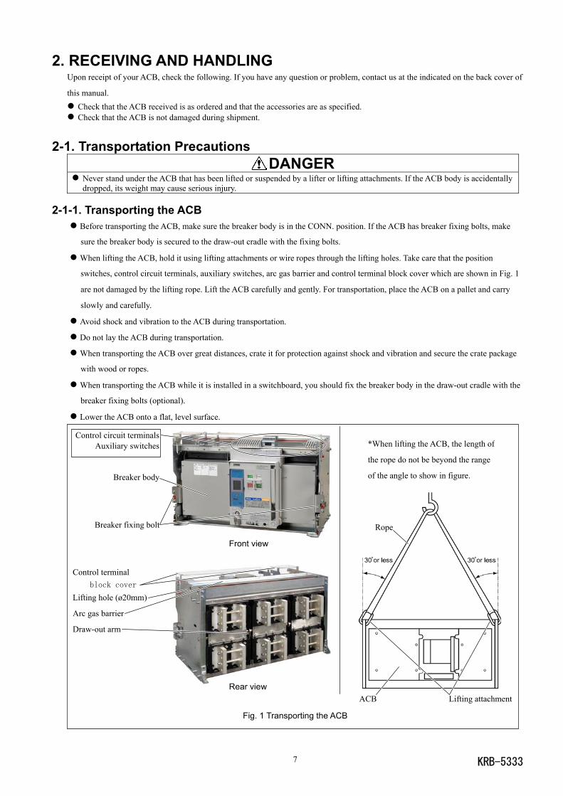
2-1-1. Transporting the ACB Before transporting the ACB, make sure the breaker body is in the CONN. position. If the ACB has breaker fixing bolts, make
sure the breaker body is secured to the draw-out cradle with the fixing bolts.
When lifting the ACB, hold it using lifting attachments or wire ropes through the lifting holes. Take care that the position
switches, control circuit terminals, auxiliary switches, arc gas barrier and control terminal block cover which are shown in Fig. 1
are not damaged by the lifting rope. Lift the ACB carefully and gently. For transportation, place the ACB on a pallet and carry
slowly and carefully.
Avoid shock and vibration to the ACB during transportation.
Do not lay the ACB during transportation.
When transporting the ACB over great distances, crate it for protection against shock and vibration and secure the crate package
with wood or ropes.
When transporting the ACB while it is installed in a switchboard, you should fix the breaker body in the draw-out cradle with the
breaker fixing bolts (optional).
Lower the ACB onto a flat, level surface.
Front view
Rear view
Fig. 1 Transporting the ACB
KRB-5333 8
Front cover
Control circuit contact
Lifting plate
*When lifting the breaker body, the length of the rope do
not be beyond the range of the angle to show in figure.
Breaker body Lifting attachment
Lifting plate
Rope
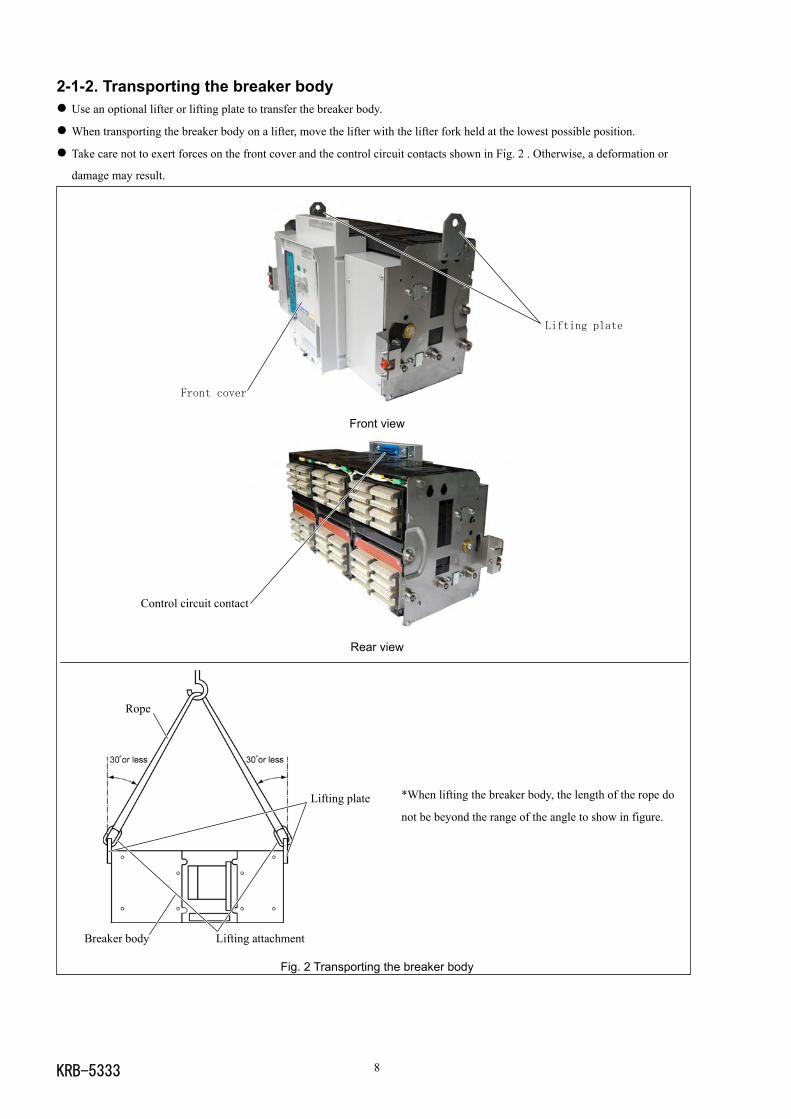
2-1-2. Transporting the breaker body Use an optional lifter or lifting plate to transfer the breaker body.
When transporting the breaker body on a lifter, move the lifter with the lifter fork held at the lowest possible position.
Take care not to exert forces on the front cover and the control circuit contacts shown in Fig. 2 . Otherwise, a deformation or
damage may result.
Front view
Rear view
Fig. 2 Transporting the breaker body
KRB-53339
Control circuit terminalsAuxiliary switches
Control circuit contacts
Control terminal block cover
Arc gas barrier
Lifting hole (ø20mm)
Draw-out arm
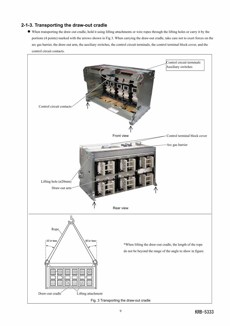
2-1-3. Transporting the draw-out cradle When transporting the draw-out cradle, hold it using lifting attachments or wire ropes through the lifting holes or carry it by the
portions (4 points) marked with the arrows shown in Fig 3. When carrying the draw-out cradle, take care not to exert forces on the
arc gas barrier, the draw-out arm, the auxiliary switches, the control circuit terminals, the control terminal block cover, and the
control circuit contacts.
Front view
Rear view
Fig. 3 Transporting the draw-out cradle
*When lifting the draw-out cradle, the length of the rope
do not be beyond the range of the angle to show in figure.
Draw-out cradle Lifting attachment
Rope
KRB-5333 10
2-2. Storage PrecautionsIt is recommended that the ACB be used as soon as you have received it. If it is necessary to store the ACB, note the following:
Store the ACB in a dry indoor location to prevent condensation due to sudden changes in ambient temperature. Condensation has
a harmful effect on the ACB insulation.
Store the ACB in a clean place free of corrosive gases and dust. In particular, exposure to a mixture of moisture and cement dust
may cause corrosion damage to metal parts of the ACB.
Place the ACB on a flat, level surface in its normal position (Do not lay the ACB).
Do not place the ACB directly on the floor. Do not stack the ACBs during storage.
2-3. Installation Precautions CAUTION
Electrical work must be done by competent persons. Do not place the ACB in such an area that is subject to high temperatures, high humidity, dusty air, corrosive gases, strongvibration and shock, or other unusual conditions. Mounting the ACB in such an area could cause a fire or malfunction.
Be careful to prevent foreign objects (such as debris, concrete powder, dust, chippings, and iron powder) and oil or rainwaterfrom entering the ACB. These materials inside the ACB could cause a fire or malfunction.
Prior to commencing any work on the ACB, open an upstream circuit breaker or the like to isolate all sources ofpower/voltage. Otherwise, electric shock may result.
Fix the draw-out cradle of the ACB firmly on a flat, level surface using mounting screws. Otherwise, the draw-out operationmay cause the breaker body or the draw-out cradle to fall, resulting in damage to the ACB or personal injury.
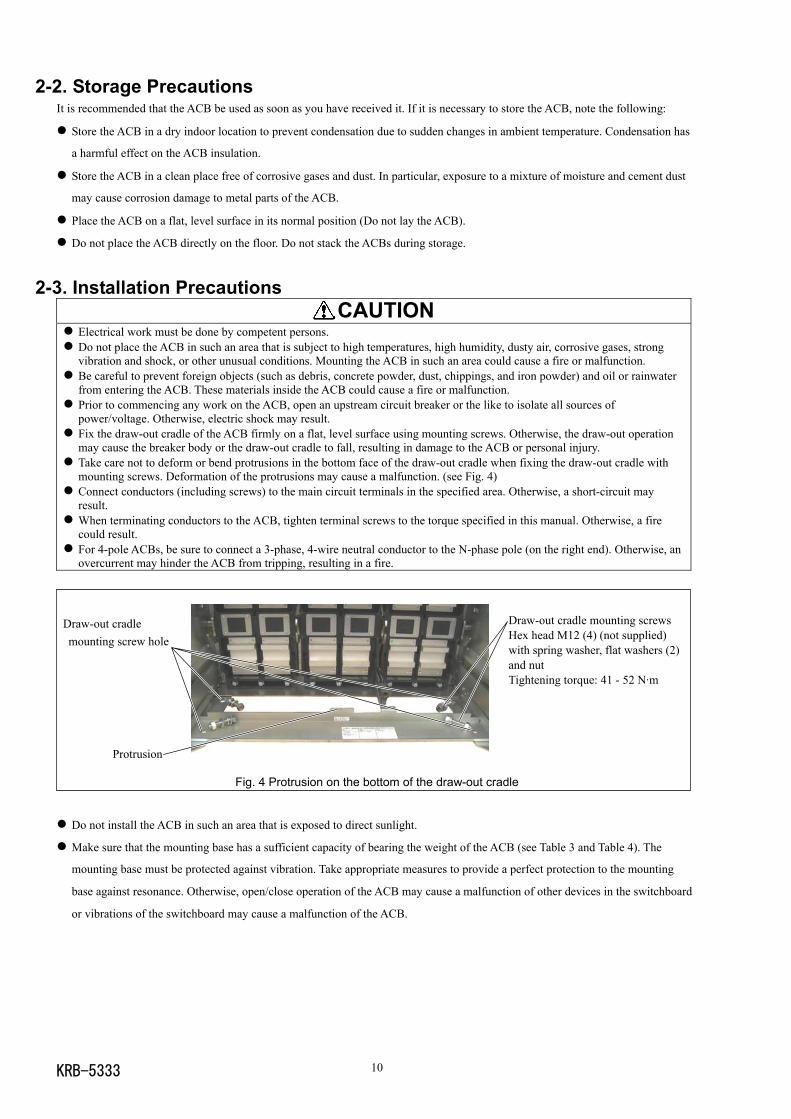
Take care not to deform or bend protrusions in the bottom face of the draw-out cradle when fixing the draw-out cradle withmounting screws. Deformation of the protrusions may cause a malfunction. (see Fig. 4)
Connect conductors (including screws) to the main circuit terminals in the specified area. Otherwise, a short-circuit mayresult.
When terminating conductors to the ACB, tighten terminal screws to the torque specified in this manual. Otherwise, a firecould result.
For 4-pole ACBs, be sure to connect a 3-phase, 4-wire neutral conductor to the N-phase pole (on the right end). Otherwise, anovercurrent may hinder the ACB from tripping, resulting in a fire.
Fig. 4 Protrusion on the bottom of the draw-out cradle
Do not install the ACB in such an area that is exposed to direct sunlight.
Make sure that the mounting base has a sufficient capacity of bearing the weight of the ACB (see Table 3 and Table 4). The
mounting base must be protected against vibration. Take appropriate measures to provide a perfect protection to the mounting
base against resonance. Otherwise, open/close operation of the ACB may cause a malfunction of other devices in the switchboard
or vibrations of the switchboard may cause a malfunction of the ACB.
Draw-out cradle mounting screwsHex head M12 (4) (not supplied)with spring washer, flat washers (2)and nutTightening torque: 41 - 52 N·m
Draw-out cradlemounting screw hole
Protrusion
KRB-533311
Use the following screws with appropriate length for the main circuit terminals.
Main circuit terminal screws: Hex head M10, with flat washers (2), spring washer (1) and nut (1) per screw
Tightening torque: 22.5 - 37.2 N·m
Table 1 Number of main circuit terminal screws requiredACB type AR650S, AR663S, AR663H
Vertical terminals 48/64Number of main circuitterminal screws(3/4-pole) Horizontal terminals* 36/48
Use the following screw for the ground terminal. The screw must have a length that allows it to be inserted 4 - 9 mm into the
ground terminal M8 tapped hole.
Ground terminal screw: M8 (1) with spring washer and flat washer
Tightening torque: 11.8 - 14.7 N·m
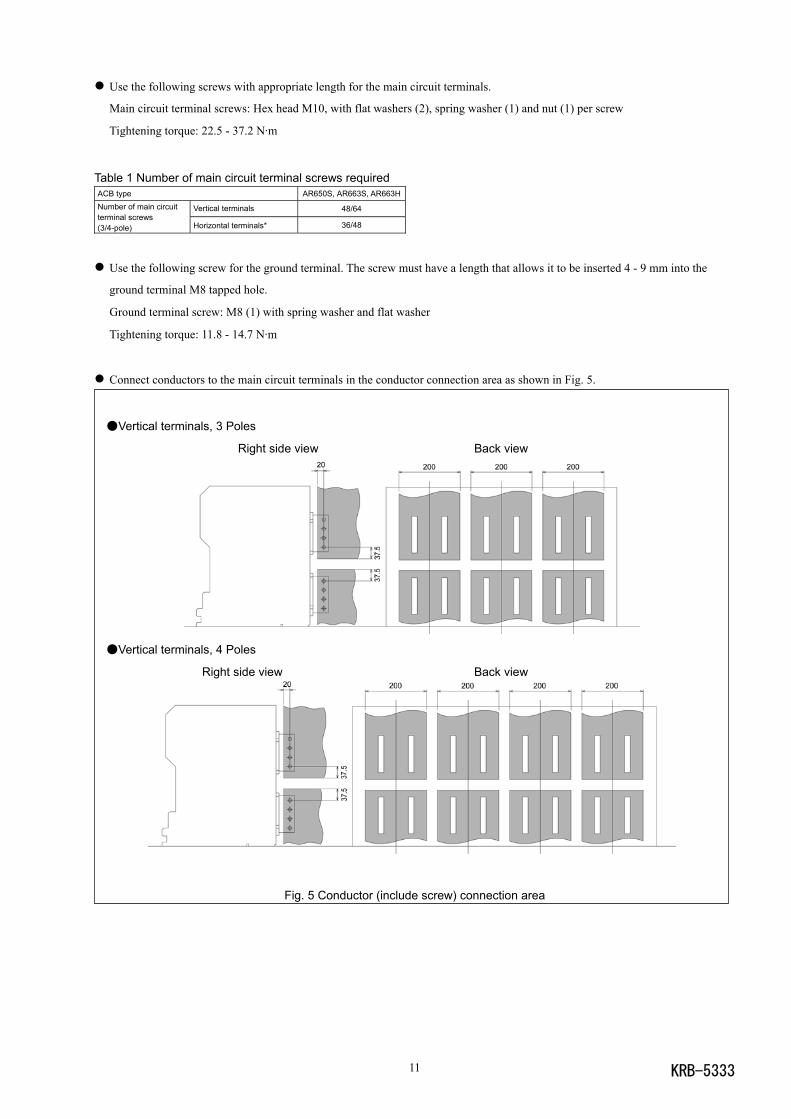
Connect conductors to the main circuit terminals in the conductor connection area as shown in Fig. 5.
Vertical terminals, 3 Poles
Right side view Back view
Vertical terminals, 4 Poles
Right side view Back view
Fig. 5 Conductor (include screw) connection area
KRB-5333 12
ACB Support
Conductor
ACB
Support
Conductor
Use a support to hold conductors securely at distance L as shown in Fig. 6 and Table 2. Such a support will help preventing the
conductors and main circuit terminals from being deformed or damaged due to a large electromagnetic force caused by any fault
current. Use a high-quality insulating material for a support and secure enough insulation distance.
Table 2 Distance LShort-circuit current (kA) 30 50 65 80 100 120 135
DistanceL (mm) Type AR650S,663S,663H 350 300 250 150 150 150 150
Fig. 6 Support mounting
The following procedure makes it easy to make connections with screw terminals of position switches, control circuit terminals,
and auxiliary switches.
(1) Draw out the breaker body to the removed position, and remove it using an optional lifter or lifting plate. Refer to sections 4-2-2
and 2-1-2.
(2) If the ACB is equipped with the control terminal block cover, loosen both the cover fixing screws and remove the cover.
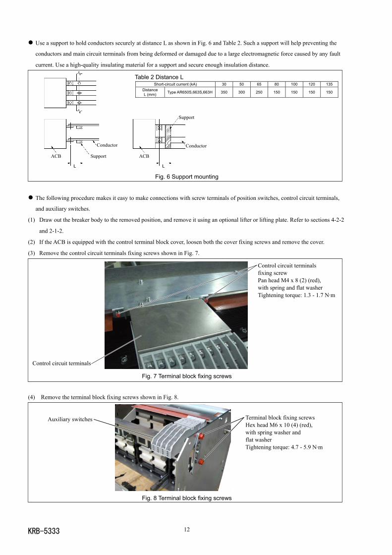
(3) Remove the control circuit terminals fixing screws shown in Fig. 7.
Fig. 7 Terminal block fixing screws
(4) Remove the terminal block fixing screws shown in Fig. 8.
Fig. 8 Terminal block fixing screws
Terminal block fixing screwsHex head M6 x 10 (4) (red),with spring washer andflat washerTightening torque: 4.7 - 5.9 N·m
Auxiliary switches
Control circuit terminals
Control circuit terminalsfixing screwPan head M4 x 8 (2) (red),with spring and flat washerTightening torque: 1.3 - 1.7 N·m
KRB-533313
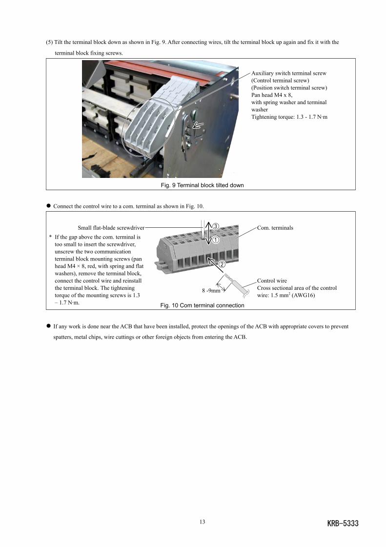
(5) Tilt the terminal block down as shown in Fig. 9. After connecting wires, tilt the terminal block up again and fix it with the
terminal block fixing screws.
Fig. 9 Terminal block tilted down
Connect the control wire to a com. terminal as shown in Fig. 10.
Fig. 10 Com terminal connection
If any work is done near the ACB that have been installed, protect the openings of the ACB with appropriate covers to prevent
spatters, metal chips, wire cuttings or other foreign objects from entering the ACB.
Com. terminals
Control wireCross sectional area of the controlwire: 1.5 mm2 (AWG16)
Small flat-blade screwdriver* If the gap above the com. terminal is
too small to insert the screwdriver,unscrew the two communicationterminal block mounting screws (panhead M4 × 8, red, with spring and flatwashers), remove the terminal block,connect the control wire and reinstallthe terminal block. The tighteningtorque of the mounting screws is 1.3– 1.7 N·m.
8 -9mm
Auxiliary switch terminal screw(Control terminal screw)(Position switch terminal screw)Pan head M4 x 8,with spring washer and terminalwasherTightening torque: 1.3 - 1.7 N·m
KRB-5333 14
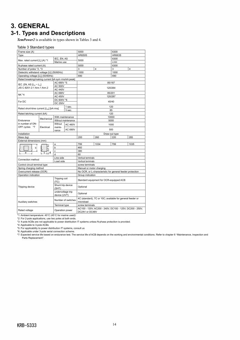
3. GENERAL3-1. Types and Descriptions
TemPower2 is available in types shown in Tables 3 and 4.
Table 3 Standard typesFrame size (A) 5000 6300Type AR650S AR663S
IEC, EN, AS 6300Max. rated current [In] (A) *1
Marine use5000
6300N-phase rated current (A) 5000 6300Number of poles *2, *3 3 4 3 4Dielectric withstand voltage [Ui] (50/60Hz) 1000 1000Operating voltage [Ue] (50/60Hz) 690 690Rated breaking/making current [kA sym rms/kA peak]
AC 690V *5 85/187AC 500V
IEC ,EN, AS [ICS = ICU]JIS C 8201-2-1 Ann.1 Ann.2
AC 440V120/264
AC 690V 85/201NK *4
AC 450V 120/287DC 600V *6
For DCDC 250V
40/40
1 sec. 120Rated short-time current [ICW] [kA rms]
3 sec. 85Rated latching current (kA) 120
With maintenance 10000Mechanical
Without maintenance 5000
AC 460V 1000
Endurancein number of ON-OFF cycles *7 Electrical
Withoutmainte-nance AC 690V 500
Installation Draw-out typeMass (kg) 200 260 220 285External dimensions (mm)
a 799 1034 799 1035b 460c 380d 60Line side Vertical terminals
Connection methodLoad side Vertical terminals
Control circuit terminal type screw terminalsSpring charging method Manual or motor chargingOvercurrent release (OCR) No OCR, or L-characteristic for general feeder protectionOperation indication Group indication
Tripping coil(TC)
Standard equipment for OCR-equipped ACB
Shunt trip device(SHT)
OptionalTripping device
undervoltage tripdevice (UVT)
Optional
Number of switches4C (standard), 7C or 10C; available for general feeder ormicroloadAuxiliary switches
Terminal type screw terminals
Rated voltage Operation powerAC100 - 120V, AC200 - 240V, DC100 - 125V, DC200 - 250V,DC24V or DC48V
*1: Ambient temperature: 40°C (45°C for marine used))*2: For 2-pole applications, use two poles at both ends.*3: 4-pole ACBs are not applicable to power distribution IT systems unless N-phase protection is provided.*4: Applicable to 3-pole ACBs*5: For applicability to power distribution IT systems, consult us*6: Applicable under 3-pole serial connection scheme.*7: Expected service life based on endurance test. The service life of ACB depends on the working and environmental conditions. Refer to chapter 6 “Maintenance, Inspection and
Parts Replacement”.
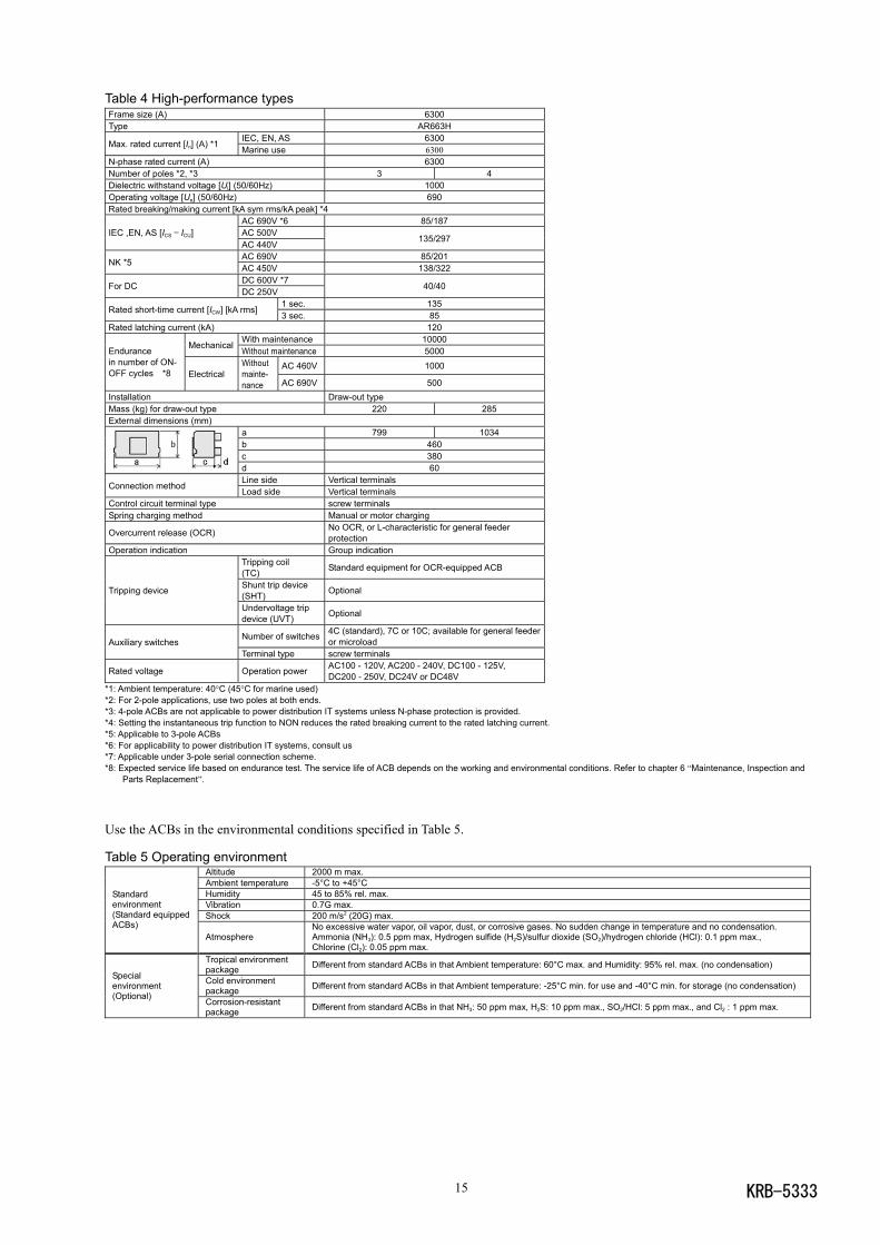
KRB-533315
Table 4 High-performance typesFrame size (A) 6300Type AR663H
IEC, EN, AS 6300Max. rated current [In] (A) *1 Marine use 6300N-phase rated current (A) 6300Number of poles *2, *3 3 4Dielectric withstand voltage [Ui] (50/60Hz) 1000Operating voltage [Ue] (50/60Hz) 690Rated breaking/making current [kA sym rms/kA peak] *4
AC 690V *6 85/187AC 500VIEC ,EN, AS [ICS = ICU]AC 440V
135/297
AC 690V 85/201NK *5 AC 450V 138/322
DC 600V *7For DC DC 250V 40/40
1 sec. 135Rated short-time current [ICW] [kA rms]
3 sec. 85Rated latching current (kA) 120
With maintenance 10000Mechanical
Without maintenance 5000AC 460V 1000
Endurancein number of ON-OFF cycles *8 Electrical
Withoutmainte-nance AC 690V 500
Installation Draw-out typeMass (kg) for draw-out type 220 285External dimensions (mm)
a 799 1034b 460c 380d 60Line side Vertical terminals
Connection method Load side Vertical terminalsControl circuit terminal type screw terminalsSpring charging method Manual or motor charging
Overcurrent release (OCR) No OCR, or L-characteristic for general feederprotection
Operation indication Group indicationTripping coil(TC) Standard equipment for OCR-equipped ACB
Shunt trip device(SHT) OptionalTripping device
Undervoltage tripdevice (UVT) Optional
Number of switches 4C (standard), 7C or 10C; available for general feederor microloadAuxiliary switches
Terminal type screw terminals
Rated voltage Operation power AC100 - 120V, AC200 - 240V, DC100 - 125V,DC200 - 250V, DC24V or DC48V
*1: Ambient temperature: 40°C (45°C for marine used)*2: For 2-pole applications, use two poles at both ends.*3: 4-pole ACBs are not applicable to power distribution IT systems unless N-phase protection is provided.*4: Setting the instantaneous trip function to NON reduces the rated breaking current to the rated latching current.*5: Applicable to 3-pole ACBs*6: For applicability to power distribution IT systems, consult us*7: Applicable under 3-pole serial connection scheme.*8: Expected service life based on endurance test. The service life of ACB depends on the working and environmental conditions. Refer to chapter 6 “Maintenance, Inspection and
Parts Replacement”.
Use the ACBs in the environmental conditions specified in Table 5.
Table 5 Operating environmentAltitude 2000 m max.Ambient temperature -5°C to +45°CHumidity 45 to 85% rel. max.Vibration 0.7G max.Shock 200 m/s2 (20G) max.
Standardenvironment(Standard equippedACBs)
AtmosphereNo excessive water vapor, oil vapor, dust, or corrosive gases. No sudden change in temperature and no condensation.Ammonia (NH3): 0.5 ppm max, Hydrogen sulfide (H2S)/sulfur dioxide (SO2)/hydrogen chloride (HCl): 0.1 ppm max.,Chlorine (Cl2): 0.05 ppm max.
Tropical environmentpackage Different from standard ACBs in that Ambient temperature: 60°C max. and Humidity: 95% rel. max. (no condensation)
Cold environmentpackage Different from standard ACBs in that Ambient temperature: -25°C min. for use and -40°C min. for storage (no condensation)
Specialenvironment(Optional) Corrosion-resistant
package Different from standard ACBs in that NH3: 50 ppm max, H2S: 10 ppm max., SO2/HCl: 5 ppm max., and Cl2 : 1 ppm max.
KRB-5333 16
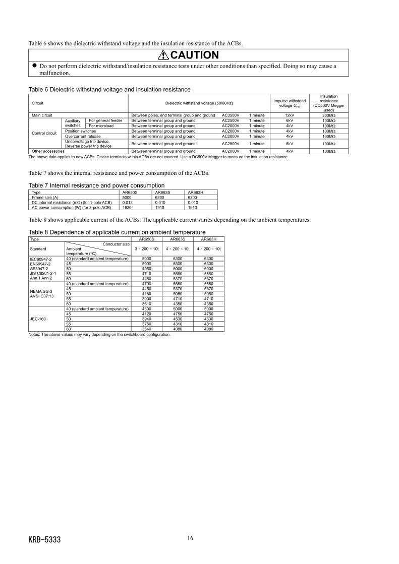
Table 6 shows the dielectric withstand voltage and the insulation resistance of the ACBs.
CAUTION Do not perform dielectric withstand/insulation resistance tests under other conditions than specified. Doing so may cause amalfunction.
Table 6 Dielectric withstand voltage and insulation resistance
Circuit Dielectric withstand voltage (50/60Hz) Impulse withstandvoltage Uimp
Insulationresistance
(DC500V Meggerused)
Main circuit Between poles, and terminal group and ground AC3500V 1 minute 12kV 300MΩFor general feeder Between terminal group and ground AC2500V 1 minute 6kV 100MΩAuxiliary
switches For microload Between terminal group and ground AC2000V 1 minute 4kV 100MΩPosition switches Between terminal group and ground AC2000V 1 minute 4kV 100MΩOvercurrent release Between terminal group and ground AC2000V 1 minute 4kV 100MΩ
Control circuit
Undervoltage trip device,Reverse power trip device Between terminal group and ground AC2500V 1 minute 6kV 100MΩ
Other accessories Between terminal group and ground AC2000V 1 minute 4kV 100MΩThe above data applies to new ACBs. Device terminals within ACBs are not covered. Use a DC500V Megger to measure the insulation resistance.
Table 7 shows the internal resistance and power consumption of the ACBs.
Table 7 Internal resistance and power consumptionType AR650S AR663S AR663HFrame size (A) 5000 6300 6300DC internal resistance (mΩ) (for 1-pole ACB) 0.012 0.010 0.010AC power consumption (W) (for 3-pole ACB) 1620 1910 1910
Table 8 shows applicable current of the ACBs. The applicable current varies depending on the ambient temperatures.
Table 8 Dependence of applicable current on ambient temperatureType AR650S AR663S AR663H
StandardConductor size
Ambienttemperature (°C)
3 × 200 × 10t 4 × 200 × 10t 4 × 200 × 10t
40 (standard ambient temperature) 5000 6300 630045 5000 6300 630050 4950 6000 600055 4710 5680 5680
IEC60947-2EN60947-2AS3947-2JIS C8201-2-1Ann.1 Ann.2 60 4450 5370 5370
40 (standard ambient temperature) 4700 5680 568045 4450 5370 537050 4180 5050 505055 3900 4710 4710
NEMA,SG-3ANSI C37.13
60 3610 4350 435040 (standard ambient temperature) 4300 5000 500045 4120 4750 475050 3940 4530 453055 3750 4310 4310
JEC-160
60 3540 4080 4080Notes: The above values may vary depending on the switchboard configuration.
KRB-533317
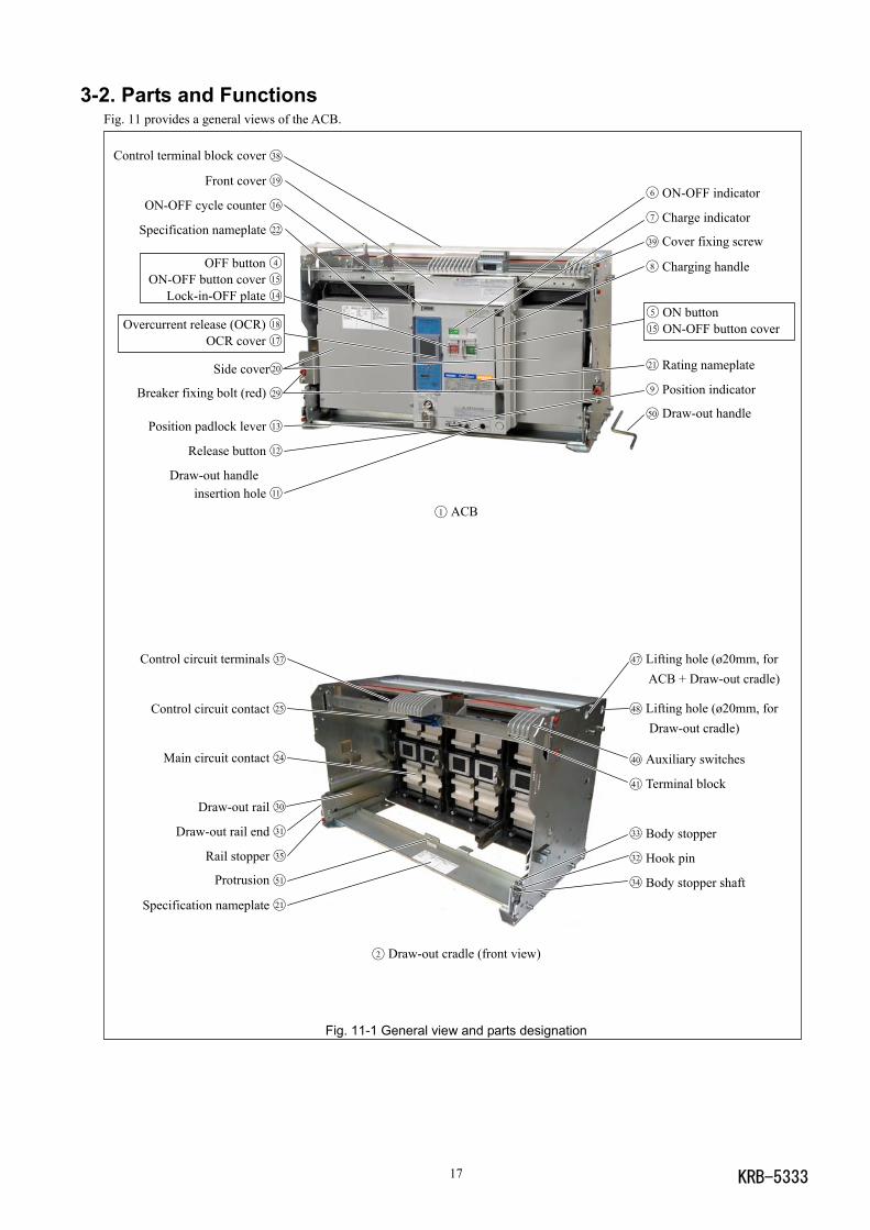
OFF button 4
ON-OFF button cover 15
Lock-in-OFF plate 14
5 ON button15 ON-OFF button cover
6 ON-OFF indicator
7 Charge indicator
39 Cover fixing screw
8 Charging handle
Overcurrent release (OCR) 18
OCR cover 17
Control terminal block cover 38
Front cover 19
ON-OFF cycle counter 16
Specification nameplate 22
21 Rating nameplate
9 Position indicator
50 Draw-out handlePosition padlock lever 13
Release button 12
Draw-out handleinsertion hole 11
Side cover20
Breaker fixing bolt (red) 29
Control circuit terminals 37
Control circuit contact 25
Main circuit contact 24
Draw-out rail 30
Draw-out rail end 31
Rail stopper 35
Protrusion 51
Specification nameplate 21
47 Lifting hole (ø20mm, for ACB + Draw-out cradle)
48 Lifting hole (ø20mm, for Draw-out cradle)
40 Auxiliary switches
41 Terminal block
33 Body stopper
32 Hook pin
34 Body stopper shaft
3-2. Parts and FunctionsFig. 11 provides a general views of the ACB.
1 ACB
2 Draw-out cradle (front view)
Fig. 11-1 General view and parts designation
KRB-5333 18
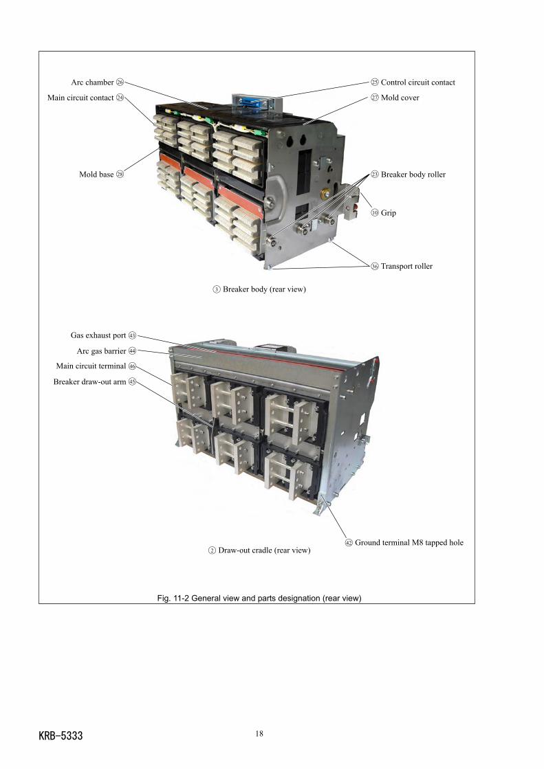
3 Breaker body (rear view)
2 Draw-out cradle (rear view)
Fig. 11-2 General view and parts designation (rear view)
Gas exhaust port 43
Arc gas barrier 44
Main circuit terminal 46
Breaker draw-out arm 45
Arc chamber 26
Main circuit contact 24
Mold base 28
25 Control circuit contact
27 Mold cover
23 Breaker body roller
42 Ground terminal M8 tapped hole
36 Transport roller
10 Grip
KRB-533319
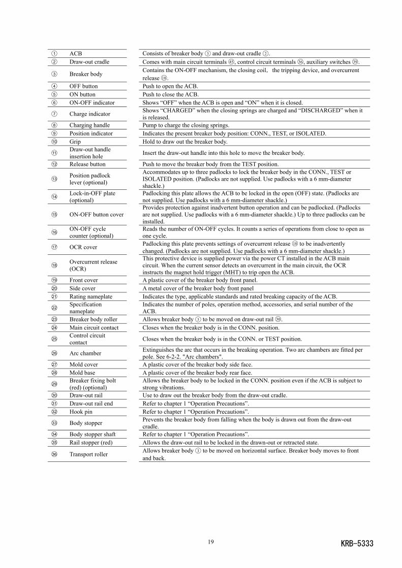
1 ACB Consists of breaker body 3 and draw-out cradle 2 .2 Draw-out cradle Comes with main circuit terminals 45 , control circuit terminals 36 , auxiliary switches 39 .
3 Breaker body Contains the ON-OFF mechanism, the closing coil,the tripping device, and overcurrentrelease 18 .
4 OFF button Push to open the ACB.5 ON button Push to close the ACB.6 ON-OFF indicator Shows “OFF” when the ACB is open and “ON” when it is closed.
7 Charge indicator Shows “CHARGED” when the closing springs are charged and “DISCHARGED” when itis released.
8 Charging handle Pump to charge the closing springs.9 Position indicator Indicates the present breaker body position: CONN., TEST, or ISOLATED.10 Grip Hold to draw out the breaker body.
11Draw-out handleinsertion hole Insert the draw-out handle into this hole to move the breaker body.
12 Release button Push to move the breaker body from the TEST position.
13Position padlocklever (optional)
Accommodates up to three padlocks to lock the breaker body in the CONN., TEST orISOLATED position. (Padlocks are not supplied. Use padlocks with a 6 mm-diametershackle.)
14Lock-in-OFF plate(optional)
Padlocking this plate allows the ACB to be locked in the open (OFF) state. (Padlocks arenot supplied. Use padlocks with a 6 mm-diameter shackle.)
15 ON-OFF button coverProvides protection against inadvertent button operation and can be padlocked. (Padlocksare not supplied. Use padlocks with a 6 mm-diameter shackle.) Up to three padlocks can beinstalled.
16ON-OFF cyclecounter (optional)
Reads the number of ON-OFF cycles. It counts a series of operations from close to open asone cycle.
17 OCR cover Padlocking this plate prevents settings of overcurrent release 18 to be inadvertentlychanged. (Padlocks are not supplied. Use padlocks with a 6 mm-diameter shackle.)
18Overcurrent release(OCR)
This protective device is supplied power via the power CT installed in the ACB maincircuit. When the current sensor detects an overcurrent in the main circuit, the OCRinstructs the magnet hold trigger (MHT) to trip open the ACB.
19 Front cover A plastic cover of the breaker body front panel.20 Side cover A metal cover of the breaker body front panel21 Rating nameplate Indicates the type, applicable standards and rated breaking capacity of the ACB.
22Specificationnameplate
Indicates the number of poles, operation method, accessories, and serial number of theACB.
23 Breaker body roller Allows breaker body 3 to be moved on draw-out rail 30 .24 Main circuit contact Closes when the breaker body is in the CONN. position.
25Control circuitcontact Closes when the breaker body is in the CONN. or TEST position.
26 Arc chamber Extinguishes the arc that occurs in the breaking operation. Two arc chambers are fitted perpole. See 6-2-2. "Arc chambers".
27 Mold cover A plastic cover of the breaker body side face.28 Mold base A plastic cover of the breaker body rear face.
29Breaker fixing bolt(red) (optional)
Allows the breaker body to be locked in the CONN. position even if the ACB is subject tostrong vibrations.
30 Draw-out rail Use to draw out the breaker body from the draw-out cradle.31 Draw-out rail end Refer to chapter 1 “Operation Precautions”.32 Hook pin Refer to chapter 1 “Operation Precautions”.
33 Body stopper Prevents the breaker body from falling when the body is drawn out from the draw-outcradle.
34 Body stopper shaft Refer to chapter 1 “Operation Precautions”.35 Rail stopper (red) Allows the draw-out rail to be locked in the drawn-out or retracted state.
36 Transport roller Allows breaker body 3 to be moved on horizontal surface. Breaker body moves to frontand back.
KRB-5333 20
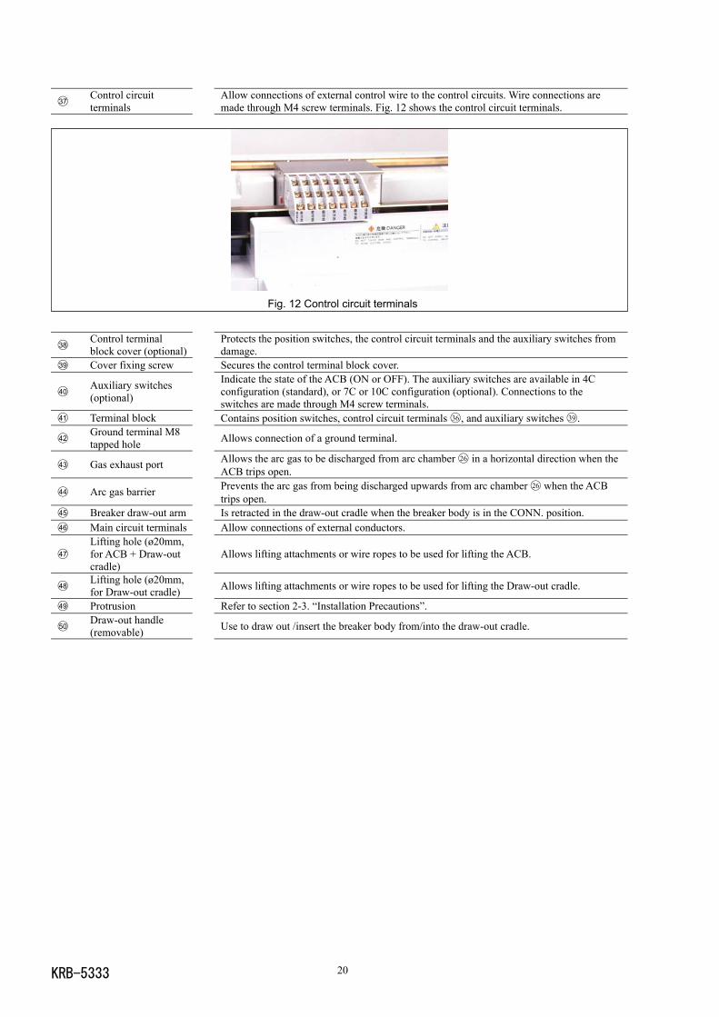
37Control circuitterminals
Allow connections of external control wire to the control circuits. Wire connections aremade through M4 screw terminals. Fig. 12 shows the control circuit terminals.
Fig. 12 Control circuit terminals
38Control terminalblock cover (optional)
Protects the position switches, the control circuit terminals and the auxiliary switches fromdamage.
39 Cover fixing screw Secures the control terminal block cover.
40Auxiliary switches(optional)
Indicate the state of the ACB (ON or OFF). The auxiliary switches are available in 4Cconfiguration (standard), or 7C or 10C configuration (optional). Connections to theswitches are made through M4 screw terminals.
41 Terminal block Contains position switches, control circuit terminals 36 , and auxiliary switches 39 .
42Ground terminal M8tapped hole Allows connection of a ground terminal.
43 Gas exhaust port Allows the arc gas to be discharged from arc chamber 26 in a horizontal direction when theACB trips open.
44 Arc gas barrier Prevents the arc gas from being discharged upwards from arc chamber 26 when the ACBtrips open.
45 Breaker draw-out arm Is retracted in the draw-out cradle when the breaker body is in the CONN. position.46 Main circuit terminals Allow connections of external conductors.
47Lifting hole (ø20mm,for ACB + Draw-outcradle)
Allows lifting attachments or wire ropes to be used for lifting the ACB.
48Lifting hole (ø20mm,for Draw-out cradle) Allows lifting attachments or wire ropes to be used for lifting the Draw-out cradle.
49 Protrusion Refer to section 2-3. “Installation Precautions”.
50Draw-out handle(removable) Use to draw out /insert the breaker body from/into the draw-out cradle.
KRB-533321
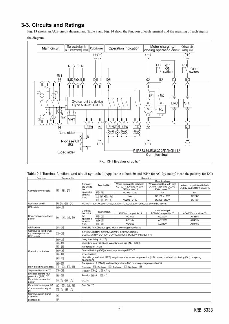
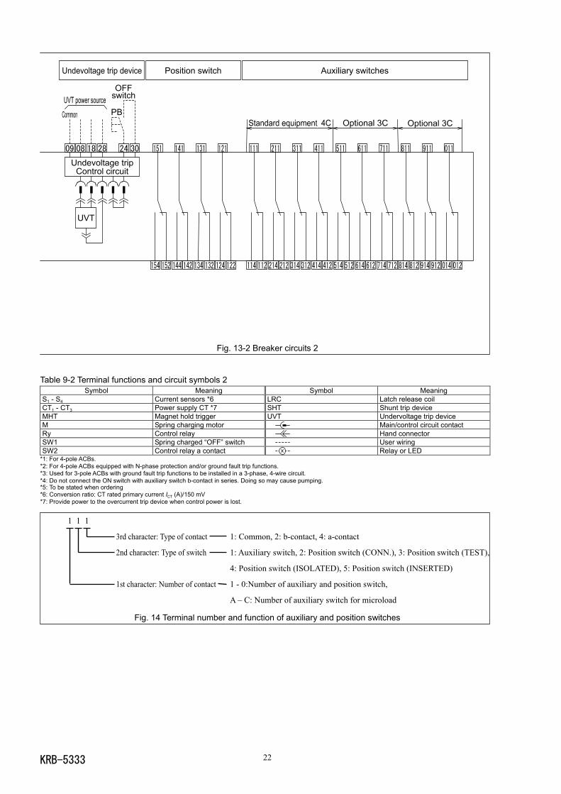
3-3. Circuits and RatingsFig. 13 shows an ACB circuit diagram and Table 9 and Fig. 14 show the function of each terminal and the meaning of each sign in
the diagram.
Fig. 13-1 Breaker circuits 1
Table 9-1 Terminal functions and circuit symbols 1 (Applicable to both 50 and 60Hz for AC. and mean the polarity for DC)Function Terminal No. Remarks
Circuit voltage
Terminal No. When compatible with bothAC100 - 120V and AC200 -
240V power *5
When compatible with bothDC100 -125V and DC200 -
250V power *5
When compatible with bothDC24V and DC48V power *5
01 -11 AC100 - 120V NA NA
11 -21 NA DC100 - 125V DC24V
Control power supply 01 , 11 , 21
Connectthe unit totheapplicableterminalNos.
01 -21 AC200 - 240V DC200 - 250V DC48VOperation power 02 -22 AC100-120V, AC200-240V, DC100-125V, DC200-250V, DC24V or DC48V *5ON switch 03 -12
Circuit voltageTerminal No. AC100V compatible *5 AC200V compatible *5 AC400V compatible *508 -09 AC100V AC200V AC380V
09 -18 AC110V AC220V AC415V
Undervoltage trip devicepower 08 , 09 , 18 , 28
Connectthe unit totheapplicableterminalNos. 09 -28 AC120V AC240V AC440V
OFF switch 24 -30 Available for ACBs equipped with undervoltage trip deviceContinuous-rated shunttrip device power andOFF switch
10 -20 AC100V, AC110V, AC120V, AC200V, AC220V, AC240V,DC24V, DC48V, DC100V, DC110V, DC125V, DC200V or DC220V *5
05 -15 Long time delay trip (LT)
05 -25 Short time delay (ST) and instantaneous trip (INST/MCR)
05 -06 Pretrip alarm (PTA)
05 -16 Ground fault trip (GF) or reverse power trip (RPT) *5
05 -26 System alarm
05 -17 Line side ground fault (REF), negative-phase sequence protection (NS), contact overheat monitoring (OH) or trippingoperation *5
Operation indication
05 -27 Pretrip alarm 2 (PTA2), undervoltage alarm (UV) or spring charge operation *5Main circuit input voltage 13 , 23 , 04 , 14 R-phase -13 , S-phase -23 , T-phase -04 , N-phase -14Separate N-phase CT 19 -29 Polarity: 19 - , 29 - *3Line side ground faultprotection (REF) CT 35 -36 Polarity: 35 - ,36 -Zone interlock controlpower 33 -34 DC24V
Zone interlock signal I/O 37 , 38 , 39 , 40 See Fig. 17.Communication signalI/O 42 -41
Communication signalCommon 32
(Reserved) 07 -
KRB-5333 22
Fig. 13-2 Breaker circuits 2
Table 9-2 Terminal functions and circuit symbols 2Symbol Meaning Symbol Meaning
S1 - S4 Current sensors *6 LRC Latch release coilCT1 - CT3 Power supply CT *7 SHT Shunt trip deviceMHT Magnet hold trigger UVT Undervoltage trip deviceM Spring charging motor Main/control circuit contactRy Control relay Hand connectorSW1 Spring charged “OFF” switch User wiringSW2 Control relay a contact Relay or LED
*1: For 4-pole ACBs.*2: For 4-pole ACBs equipped with N-phase protection and/or ground fault trip functions.*3: Used for 3-pole ACBs with ground fault trip functions to be installed in a 3-phase, 4-wire circuit.*4: Do not connect the ON switch with auxiliary switch b-contact in series. Doing so may cause pumping.*5: To be stated when ordering*6: Conversion ratio: CT rated primary current ICT (A)/150 mV*7: Provide power to the overcurrent trip device when control power is lost.
1 1 1
3rd character: Type of contact 1: Common, 2: b-contact, 4: a-contact
2nd character: Type of switch 1: Auxiliary switch, 2: Position switch (CONN.), 3: Position switch (TEST),
4: Position switch (ISOLATED), 5: Position switch (INSERTED)
1st character: Number of contact 1 - 0:Number of auxiliary and position switch,
A – C: Number of auxiliary switch for microload
Fig. 14 Terminal number and function of auxiliary and position switches
KRB-533323
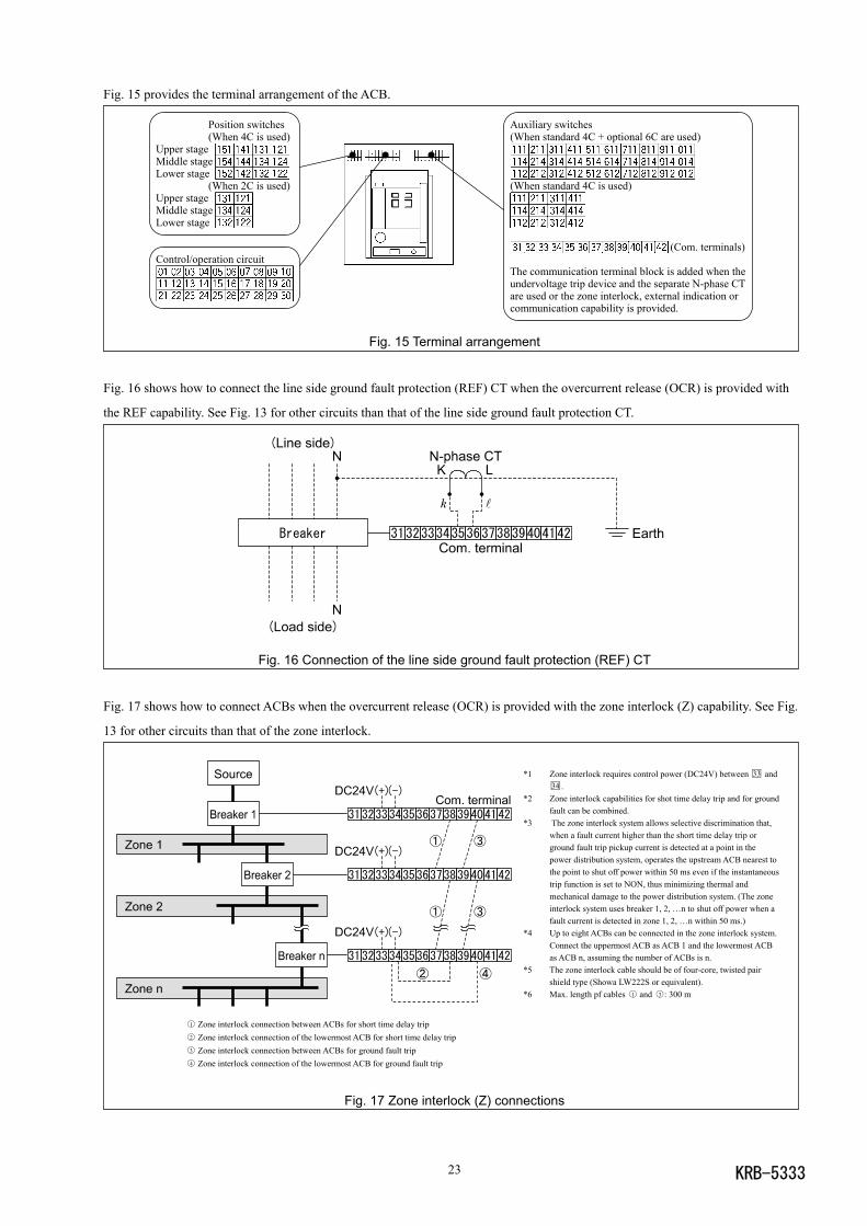
Fig. 15 provides the terminal arrangement of the ACB.
Position switches Auxiliary switches(When 4C is used) (When standard 4C + optional 6C are used)
Upper stageMiddle stageLower stage
(When 2C is used) (When standard 4C is used)Upper stageMiddle stageLower stage
(Com. terminals)Control/operation circuit
The communication terminal block is added when theundervoltage trip device and the separate N-phase CTare used or the zone interlock, external indication orcommunication capability is provided.
Fig. 15 Terminal arrangement
Fig. 16 shows how to connect the line side ground fault protection (REF) CT when the overcurrent release (OCR) is provided with
the REF capability. See Fig. 13 for other circuits than that of the line side ground fault protection CT.
Fig. 16 Connection of the line side ground fault protection (REF) CT
Fig. 17 shows how to connect ACBs when the overcurrent release (OCR) is provided with the zone interlock (Z) capability. See Fig.
13 for other circuits than that of the zone interlock.
*1 Zone interlock requires control power (DC24V) between 33 and34 .
*2 Zone interlock capabilities for shot time delay trip and for groundfault can be combined.
*3 The zone interlock system allows selective discrimination that,when a fault current higher than the short time delay trip orground fault trip pickup current is detected at a point in thepower distribution system, operates the upstream ACB nearest tothe point to shut off power within 50 ms even if the instantaneoustrip function is set to NON, thus minimizing thermal andmechanical damage to the power distribution system. (The zoneinterlock system uses breaker 1, 2, …n to shut off power when afault current is detected in zone 1, 2, …n within 50 ms.)
*4 Up to eight ACBs can be connected in the zone interlock system.Connect the uppermost ACB as ACB 1 and the lowermost ACBas ACB n, assuming the number of ACBs is n.
*5 The zone interlock cable should be of four-core, twisted pairshield type (Showa LW222S or equivalent).
*6 Max. length pf cables 1 and 3 : 300 m
Fig. 17 Zone interlock (Z) connections
1 Zone interlock connection between ACBs for short time delay trip2 Zone interlock connection of the lowermost ACB for short time delay trip3 Zone interlock connection between ACBs for ground fault trip4 Zone interlock connection of the lowermost ACB for ground fault trip
KRB-5333 24
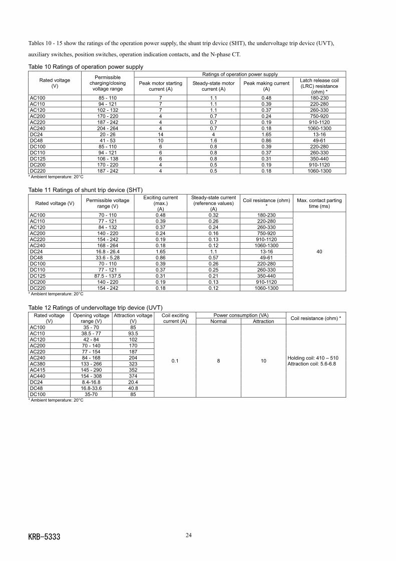
Tables 10 - 15 show the ratings of the operation power supply, the shunt trip device (SHT), the undervoltage trip device (UVT),
auxiliary switches, position switches, operation indication contacts, and the N-phase CT.
Table 10 Ratings of operation power supplyRatings of operation power supply
Rated voltage(V)
Permissiblecharging/closing
voltage rangePeak motor starting
current (A)Steady-state motor
current (A)Peak making current
(A)
Latch release coil(LRC) resistance
(ohm) *AC100 85 - 110 7 1.1 0.48 180-230AC110 94 - 121 7 1.1 0.39 220-280AC120 102 - 132 7 1.1 0.37 260-330AC200 170 - 220 4 0.7 0.24 750-920AC220 187 - 242 4 0.7 0.19 910-1120AC240 204 - 264 4 0.7 0.18 1060-1300DC24 20 - 26 14 4 1.65 13-16DC48 41 - 53 10 1.6 0.86 49-61DC100 85 - 110 6 0.8 0.39 220-280DC110 94 - 121 6 0.8 0.37 260-330DC125 106 - 138 6 0.8 0.31 350-440DC200 170 - 220 4 0.5 0.19 910-1120DC220 187 - 242 4 0.5 0.18 1060-1300
* Ambient temperature: 20°C
Table 11 Ratings of shunt trip device (SHT)
Rated voltage (V) Permissible voltagerange (V)
Exciting current(max.)
(A)
Steady-state current(reference values)
(A)
Coil resistance (ohm)*
Max. contact partingtime (ms)
AC100 70 - 110 0.48 0.32 180-230AC110 77 - 121 0.39 0.26 220-280AC120 84 - 132 0.37 0.24 260-330AC200 140 - 220 0.24 0.16 750-920AC220 154 - 242 0.19 0.13 910-1120AC240 168 - 264 0.18 0.12 1060-1300DC24 16.8 - 26.4 1.65 1.1 13-16DC48 33.6 - 5.28 0.86 0.57 49-61DC100 70 - 110 0.39 0.26 220-280DC110 77 - 121 0.37 0.25 260-330DC125 87.5 - 137.5 0.31 0.21 350-440DC200 140 - 220 0.19 0.13 910-1120DC220 154 - 242 0.18 0.12 1060-1300
40
* Ambient temperature: 20°C
Table 12 Ratings of undervoltage trip device (UVT)Power consumption (VA)Rated voltage
(V)Opening voltage
range (V)Attraction voltage
(V)Coil excitingcurrent (A) Normal Attraction Coil resistance (ohm) *
AC100 35 - 70 85AC110 38.5 - 77 93.5AC120 42 - 84 102AC200 70 - 140 170AC220 77 - 154 187AC240 84 - 168 204AC380 133 - 266 323AC415 145 - 290 352AC440 154 - 308 374DC24 8.4-16.8 20.4DC48 16.8-33.6 40.8DC100 35-70 85
0.1 8 10 Holding coil: 410 – 510Attraction coil: 5.6-6.8
* Ambient temperature: 20°C
KRB-533325
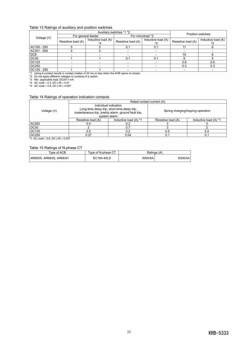
Table 13 Ratings of auxiliary and position switchesAuxiliary switches *1 *2
For general feeder For microload *3 Position switchesVoltage (V)
Resistive load (A) Inductive load (A)*4 Resistive load (A) Inductive load (A)
*5 Resistive load (A) Inductive load (A)*5
AC100 - 250 5 5 0.1 0.1 11 6AC251 - 500 5 5 - - - -DC8 - - - - 10 6DC30 1 1 0.1 0.1 6 5DC125 - - - - 0.6 0.6DC250 - - - - 0.3 0.3DC125 - 250 1 1 - - - -
*1: Using b-contact results in contact chatter of 20 ms or less when the ACB opens or closes.*2: Do not apply different voltages to contacts of a switch.*3: Min. applicable load: DC5V/1 mA*4: AC cosθ ≥ 0.3, DC L/R ≤ 0.01*5: AC cosθ ≥ 0.6, DC L/R ≤ 0.007
Table 14 Ratings of operation indication contactsRated contact current (A)
Individual indicationLong-time delay trip, short-time delay trip,
instantaneous trip, pretrip alarm, ground fault trip,system alarm
Spring charging/tripping operationVoltage (V)
Resistive load (A) Inductive load (A) *1 Resistive load (A) Inductive load (A) *1AC250 0.5 0.2 3 3DC30 2 0.7 3 2DC125 0.5 0.2 0.5 0.5DC250 0.27 0.04 0.1 0.1
*1: AC cosθ ≥ 0.6, DC L/R ≤ 0.007
Table 15 Ratings of N-phase CTType of ACB Type of N-phase CT Ratings (A)
AR650S, AR663S, AR663H EC160-40LS 5000/5A 6300/5A
KRB-5333 26
4. OPERATION4-1. Charging and Opening operation
DANGER Never touch live terminal parts. Otherwise, electric shock may result.
CAUTION Do not force down the charging handle after completion of manual charging operation. Doing so may cause a malfunction. The permissible operating voltage of the spring charging motor is 85 to 110% of the rated ac voltage or 75 to 110% of therated dc voltage. Be sure to supply a voltage within the above ranges to the motor. Otherwise, burnout may result.
Repeated open/close operation by the motor charging mechanism without pause should not exceed 15 times. If repeatedcontinuous open/close operation is inevitable, a pause of at least 20 minutes should be provided after the repetitions of 15times. Otherwise, a spring charging motor may be burnt out.
Do not bring your hand or face close to arc gas vent of the arc chamber while the ACB is energized. Otherwise, a burn mayresult from high-temperature arc gas blowing out of the arc gas vent when the ACB trips open.
If the ACB trips open automatically, remove the cause of tripping operation before re-closing the ACB. Otherwise, a firecould result.
If the ACB has the breaker fixing bolts, make sure the bolts on both sides are securely tightened before using the ACB.Loosened fixing bolts may cause a malfunction of the ACB, in particular when it is installed in such an area that is subject tostrong vibrations.
The ACBs are available in two types in terms of the closing spring charging method and the remote operation capability: a manual
charging type and a motor charging type. The manual charging type requires the charging and ON-OFF (close/open) operation to be
done manually while the motor charging type allows the operation to be done either manually or by using a motor.
4-1-1. Charging operationThe ACB can be closed only when the closing springs have been charged. Be sure to charge the closing springs before closing the
ACB. The charging operation is permitted, regardless of whether the ACB is ON (closed) or OFF (open). The procedure for charging
the closing springs is as follows:
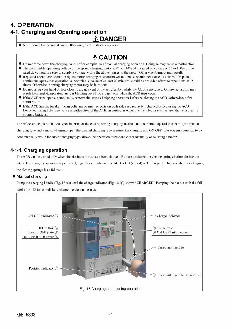
Manual chargingPump the charging handle (Fig. 18 2 ) until the charge indicator (Fig. 18 1 ) shows “CHARGED” Pumping the handle with the full
stroke 10 - 13 times will fully charge the closing springs.
Fig. 18 Charging and opening operation
1 Charge indicator
2 Charging handle
5 Draw-out handle insertion
Position indicator 3
9 ON button
8 ON-OFF button cover
ON-OFF indicator 10
OFF button 6
Lock-in-OFF plate 7ON-OFF button cover 8
KRB-533327
Motor chargingWhen the charge indicator (Fig. 18 1 ) changes to “DISCHARGED” while the specified operation voltage is applied to the control
circuit terminals 02 and 22 , the charging motor is activated to start charging the closing springs. Upon completion of the charging
operation, the charge indicator shows “CHARGED” and the charging motor is automatically deactivated. The time required for the
motor charging operation depends on the operation voltage or the ACB types, but does not exceed 10 seconds.
4-1-2. Closing operationThe ACB closing operation is not permitted unless all of the following conditions are met.
1) The charge indicator (Fig. 18 1 ) shows "CHARGED".
2) The position indicator (Fig. 18 3 ) shows "CONN.", "TEST" or "ISOLATED" (a halfway position not permitted).
3) The draw-out handle is not inserted in the draw-out handle insertion hole(Fig. 18 5 ) .
4) The OFF button (Fig. 18 6 ) is not locked with the lock-in-OFF plate (Fig. 18 7 ).
5) The specified voltage is supplied to the undervoltage trip device .
The control power of the overcurrent release (OCR) must be supplied before closing operation in order that the internal program can
be started. If the OCR trips open directly after the control power is supplied to the OCR, operation indication may be incorrect.
Manual closingOpen the ON-OFF button cover (Fig. 18 8 ) and press the ON button (Fig. 18 9 ). The ACB will be closed with a sound. The ON-
OFF indicator (Fig. 18 10 ) shows "ON" and the charge indicator (Fig. 18 1 ) shows "DISCHARGED".
Electrical closingPress the ON switch shown in Fig. 13. The latch release coil (LRC) (Fig. 13) will be excited and the ACB is closed with a sound. The
ON-OFF indicator (Fig. 18 10 ) shows "ON", the charge indicator (Fig. 18 1 ) shows "DISCHARGED", and the charging motor starts
charging the closing springs.
4-1-3. Opening operation Manual openingOpen the ON-OFF button cover (Fig. 18 8 ) and press the OFF button (Fig. 18 6 ). The ACB will trip open with a sound. The ON-
OFF indicator (Fig. 18 10 ) shows "OFF".
Electrical openingPress the OFF switch shown in Fig. 13. The shunt trip device (SHT) or the fixed type undervoltage trip device (Fig. 13) will be
excited so that the ACB trips open with a sound. The ON-OFF indicator (Fig. 18 10 ) shows "OFF".
4-1-4. Motion of trip indication and spring charge indication switchesThe trip indication and spring charge indication switches provide the breaker status as shown in Table 16.
Table 16 Motion of trip indication and spring charge indication switchesContact output
State
Closing spring ACB openType of OCR Operation Terminal No.
See Fig. 13Charged Discharged
ACB closedNot ready to close * Ready to close *
Trip 05 , 17 No change No change OFF ON OFFAll
Spring charge 05 , 27 ON OFF No change No change No change
* “Ready to close” means that all of the following conditions are met:1. The closing springs are charged.2. Opening operation is complete (At least 40 ms has elapsed after trip signal was produced).3. The OFF button is released.4. The specified voltage is applied to the undervoltage trip device (if equipped).
KRB-5333 28
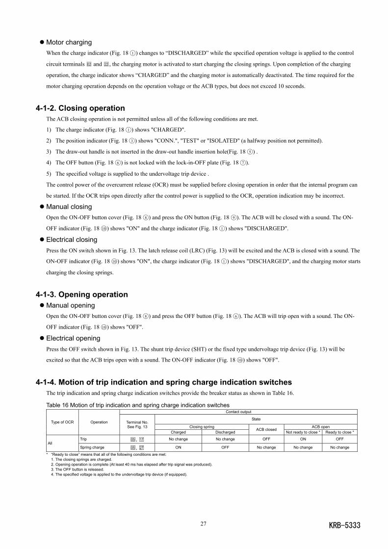
4-1-5. Motion of operation mechanismsFigs. 19 - 22 illustrate the motion of the charging and ON-OFF mechanisms.
For manual closing operation, ON button 1 rotatescounterclockwise. For electrical closing operation, pushrod 1 ' protrudes downward from the latch release coil(LRC) and charge latch trigger 2 rotates clockwise.This rotates closing trigger shaft 3 clockwise andclosing release lever 4 disengages from a semicircularpawl and rotates clockwise. And charging cam 5
rotates counterclockwise, so that charging lever 7disengages from closing spring 6 and rotatescounterclockwise. Closing cam 8 is pushed up bycharging lever 7 and rotates clockwise. At this time,each component is positioned as shown in Fig. 21.Continued to Fig. 20.
Fig. 19 Closing motion 1 (discharge motion)
Closing cam 8 rotating clockwise causes closing linkand top link 9 to be pushed straight. This rotatesclosing toggle cam 10 connected with closing link 9
counterclockwise, so that crossbar 11 rotates clockwiseand thus moving contact 12 comes in contact withstationary contact 13 . At this time, each component ispositioned as shown in Fig. 22.
Fig. 20 Closing motion 2
KRB-533329
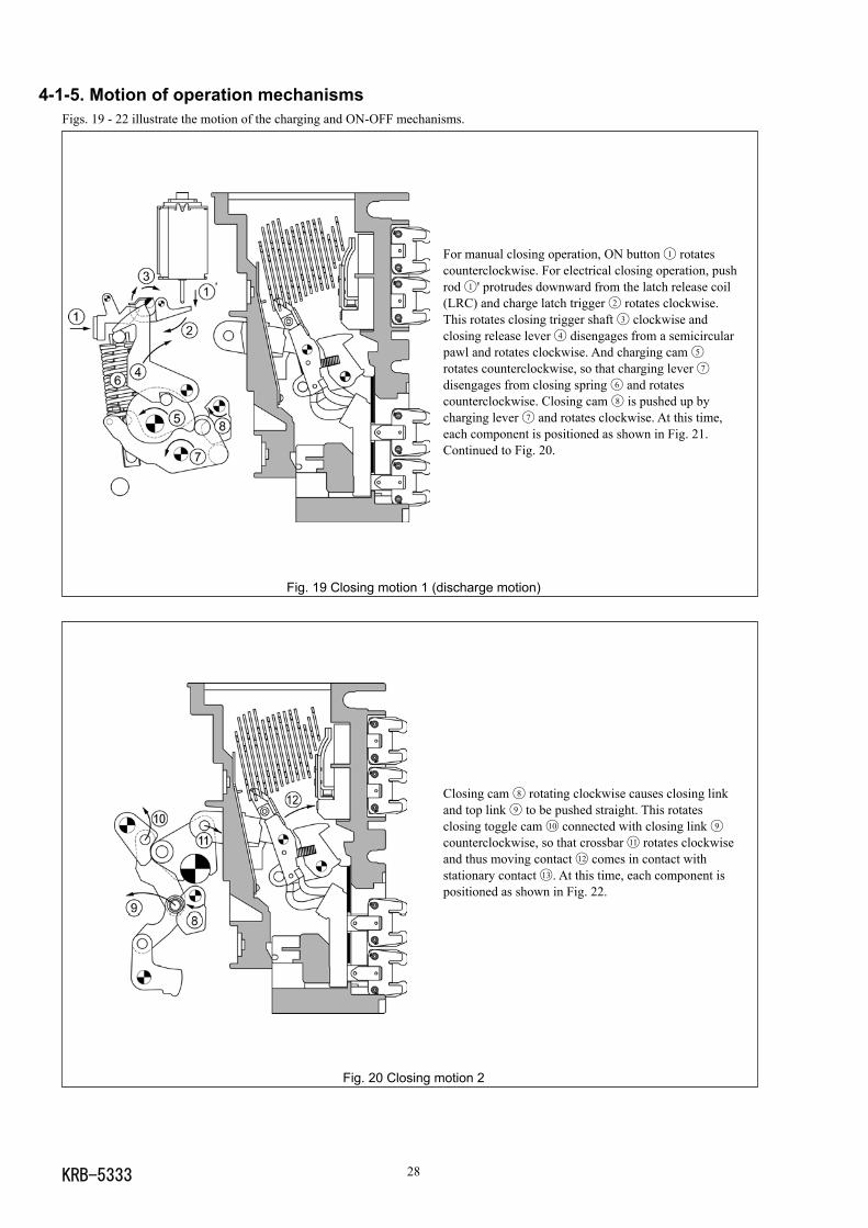
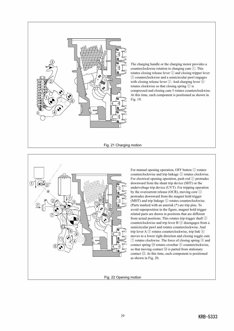
The charging handle or the charging motor provides acounterclockwise rotation to charging cam 1 . Thisrotates closing release lever 2 and closing tripper lever3 counterclockwise and a semicircular pawl engageswith closing release lever 2 . And charging lever 4rotates clockwise so that closing spring 5 iscompressed and closing cam 5 rotates counterclockwise.At this time, each component is positioned as shown inFig. 19.
Fig. 21 Charging motion
For manual opening operation, OFF button 1 rotatescounterclockwise and trip linkage 2 rotates clockwise.For electrical opening operation, push rod 1 protrudesdownward from the shunt trip device (SHT) or theundervoltage trip device (UVT). For tripping operationby the overcurrent release (OCR), moving core 1protrudes downward from the magnet hold trigger(MHT) and trip linkage 2 rotates counterclockwise.(Parts marked with an asterisk (*) are trip pins. Toavoid superposition in the figure, magnet hold triggerrelated parts are drawn in positions that are differentfrom actual positions. This rotates trip trigger shaft 3counterclockwise and trip lever B 4 disengages from asemicircular pawl and rotates counterclockwise. Andtrip lever A 5 rotates counterclockwise, trip link 6
moves to a lower right direction and closing toggle cam7 rotates clockwise. The force of closing spring 9 andcontact spring 10 rotates crossbar 8 counterclockwise,so that moving contact 10 is parted from stationarycontact 12 . At this time, each component is positionedas shown in Fig. 20.
Fig. 22 Opening motion
KRB-5333 30
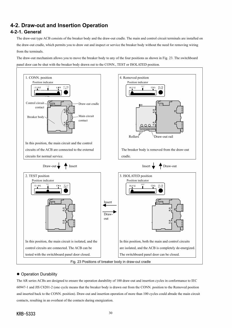
4-2. Draw-out and Insertion Operation4-2-1. General
The draw-out type ACB consists of the breaker body and the draw-out cradle. The main and control circuit terminals are installed on
the draw-out cradle, which permits you to draw out and inspect or service the breaker body without the need for removing wiring
from the terminals.
The draw-out mechanism allows you to move the breaker body to any of the four positions as shown in Fig. 23. The switchboard
panel door can be shut with the breaker body drawn out to the CONN., TEST or ISOLATED position.
1. CONN. position 4. Removed position
In this position, the main circuit and the control
circuits of the ACB are connected to the external The breaker body is removed from the draw-out
circuits for normal service. cradle.
Draw-out Insert Insert Draw-out
2. TEST position 3. ISOLATED position
Insert
Draw- out
In this position, the main circuit is isolated, and the In this position, both the main and control circuits
control circuits are connected. The ACB can be are isolated, and the ACB is completely de-energized.
tested with the switchboard panel door closed. The switchboard panel door can be closed.
Fig. 23 Positions of breaker body in draw-out cradle
Operation DurabilityThe AR series ACBs are designed to ensure the operation durability of 100 draw-out and insertion cycles in conformance to IEC
60947-1 and JIS C8201-2 (one cycle means that the breaker body is drawn out from the CONN. position to the Removed position
and inserted back to the CONN. position). Draw-out and insertion operation of more than 100 cycles could abrade the main circuit
contacts, resulting in an overheat of the contacts during energization.
Rollers Draw-out rail
Position indicator
Draw-out cradle
Main circuitcontact
Control circuitcontact
Breaker body
Position indicator
Position indicator
Position indicator
KRB-533331
7 Draw-out cradle
3 Breaker body
10 Grip
2 Breaker fixing bolt
1 Draw-out handle
Hook pin
9 Draw-out rail
8 Rail stopper
Hand connector14
ON-OFF indicator 12
Draw-out handle insertion hole4
Position lock lever 13
Position indicator 5
Release button 6
Body stopper
Body stopper shaft
Draw-out rail end 11
Draw-out direction
4-2-2. Draw-out operation DANGER
Never touch live terminal parts. Otherwise, electric shock may result. Do not leave the ACB body in the removed position. The weight of the ACB may cause serious injury.
CAUTION If the ACB has the breaker fixing bolts, be sure to loosen the bolts on both sides before draw-out operation. Otherwise,damage to the ACB may result.
Make sure the draw-out cradle is secured with mounting screws before drawing out the breaker body. Otherwise, the draw-outoperation may cause the breaker body or the draw-out cradle to fall, resulting in damage to the ACB or personal injury.
When retracting the draw-out rail into the draw-out cradle, be sure to push the rail end. Do not hold the hook pin, bodystopper, or body stopper shaft. Doing so may cause your fingers to be pinched, resulting in injury.
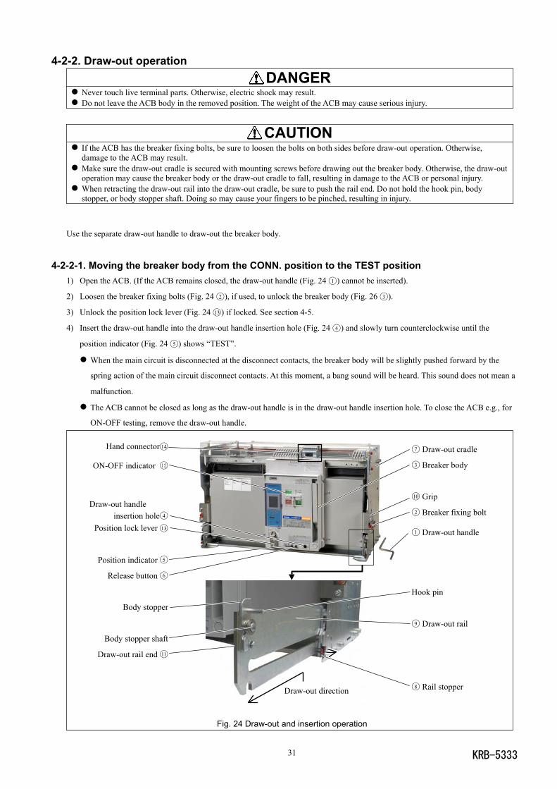
Use the separate draw-out handle to draw-out the breaker body.
4-2-2-1. Moving the breaker body from the CONN. position to the TEST position1) Open the ACB. (If the ACB remains closed, the draw-out handle (Fig. 24 1 ) cannot be inserted).
2) Loosen the breaker fixing bolts (Fig. 24 2 ), if used, to unlock the breaker body (Fig. 26 3 ).
3) Unlock the position lock lever (Fig. 24 13 ) if locked. See section 4-5.
4) Insert the draw-out handle into the draw-out handle insertion hole (Fig. 24 4 ) and slowly turn counterclockwise until the
position indicator (Fig. 24 5 ) shows “TEST”.
When the main circuit is disconnected at the disconnect contacts, the breaker body will be slightly pushed forward by the
spring action of the main circuit disconnect contacts. At this moment, a bang sound will be heard. This sound does not mean a
malfunction.
The ACB cannot be closed as long as the draw-out handle is in the draw-out handle insertion hole. To close the ACB e.g., for
ON-OFF testing, remove the draw-out handle.
Fig. 24 Draw-out and insertion operation
KRB-5333 32
4-2-2-2. Moving the breaker body from the TEST position to the ISOLATED position1) Open the ACB. (If the ACB remains closed, the draw-out handle (Fig. 24 1 ) cannot be inserted).
2) Press the release button (Fig. 24 6 ). The release button will be locked depressed.
3) Unlock the position lock lever (Fig. 24 13 ) if locked. See section 4-5.
4) Insert the draw-out handle into the draw-out handle insertion hole (Fig. 24 4 ) and slowly turn counterclockwise until the
position indicator (Fig. 24 5 ) shows “ISOLATED” and a freewheeling sound is heard. Turning the draw-out handle will unlock
the release button.
5) Remove the draw-out handle.
4-2-2-3. Moving the breaker body from the ISOLATED position to the removed position1) Make sure the draw-out cradle (Fig. 24 7 ) is secured with mounting screws.
2) Unlock the position lock lever (Fig. 24 13 ) if locked. See section 4-5.
3) Push the rail stoppers (Fig. 24 8 ) outward on both sides of the draw-out cradle to unlock the draw-out rail (Fig. 24 9 ), and then
uphold and pull out the rail until it stops. The draw-out rail will be locked again by the stoppers. (The breaker body cannot be
drawn out unless the rail is locked).
4) Holding both the grips (Fig. 24 10 ), draw out the breaker body until it stops.
If the ACB is equipped with the communication terminal block, pull out the hand connector (Fig. 24 14 ) from the
communication terminal block while drawing out the breaker body. Make sure the hand connector and control wire of the
ACB are not snagged when drawing out the breaker body again.
If the ACB is equipped with an optional auto-discharging device, the closing springs of the ACB will be automatically
discharged with a mechanical sound. This sound does not mean a malfunction.
Do not leave the ACB body on the draw-out rail pulled out.
5) Use an optional lifter or lifting plate to transfer the breaker body (Fig. 24 3 ) to a safe place. Refer to section 2-1-2.
4-2-3. Putting the breaker body back into the draw-out cradle DANGER
Never touch live terminal parts. Otherwise, electric shock may result. Do not leave the ACB body in the removed position. The weight of the ACB may cause serious injury.
CAUTION Make sure the draw-out cradle is secured with mounting screws before inserting the breaker body into the draw-out cradle.Otherwise, the insertion operation may cause the breaker body or the draw-out cradle to fall, resulting in damage to the ACBor personal injury.
When retracting the draw-out rail into the draw-out cradle, be sure to push the rail end. Do not hold the hook pin, bodystopper, or body stopper shaft. Doing so may cause your fingers to be pinched, resulting in injury.
Do not forcedly turn the draw-out handle clockwise when the breaker body is in the CONN. Position. Doing so may cause amalfunction.
If the ACB has the breaker fixing bolts, make sure the bolts on both sides are securely tightened before using the ACB.Loosened fixing bolts may cause a malfunction of the ACB, in particular when it is installed in such an area that is subject tostrong vibrations.
Use the separate draw-out handle to insert the breaker body.
4-2-3-1. Putting the breaker body back to the ISOLATED position1) Make sure the draw-out cradle (Fig. 24 7 ) is secured with mounting screws.
2) Push the rail stoppers (Fig. 24 8 ) outward on both sides of the draw-out cradle to unlock the draw-out rail (Fig. 24 9 ), and then
uphold and pull out the rail until it stops. The draw-out rail will be locked again by the stoppers. (The breaker body (Fig. 24 3 )
KRB-533333
cannot be inserted unless the rail is locked).
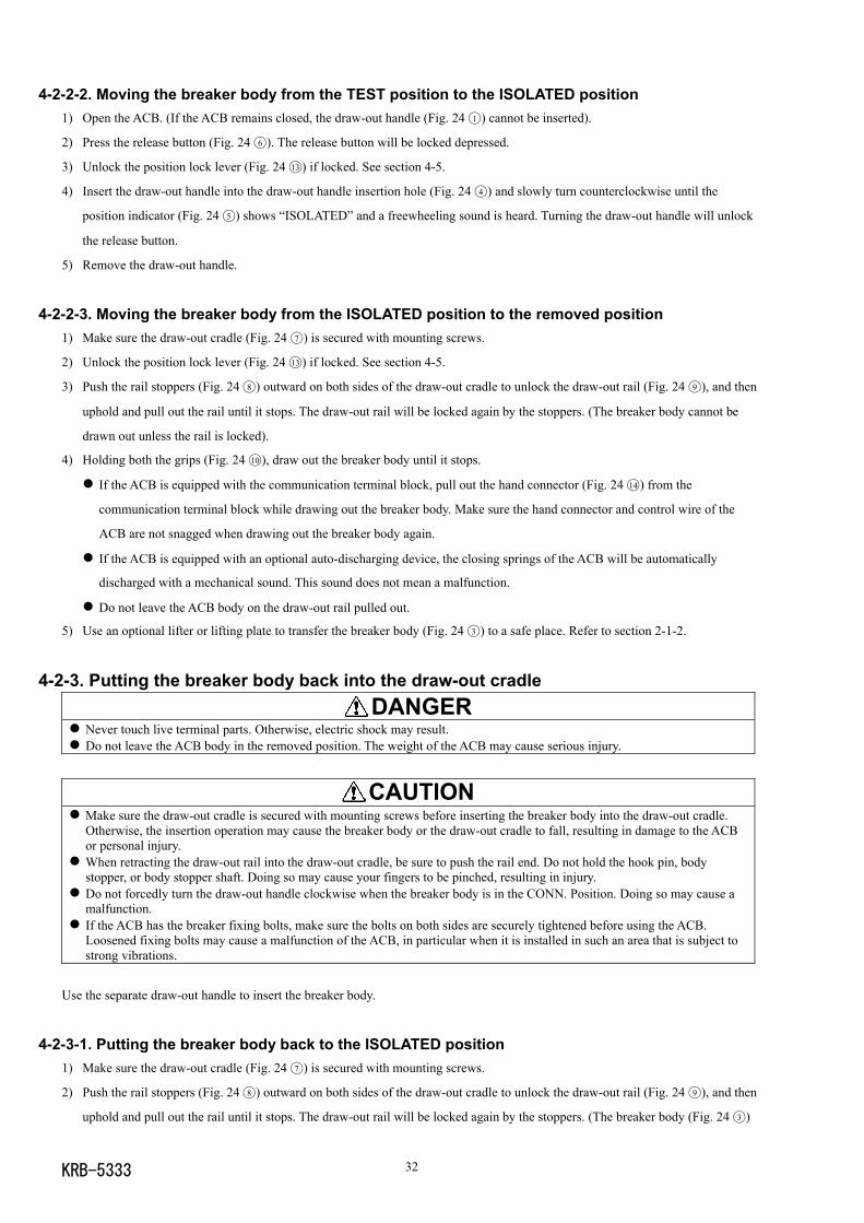
3) Use an optional lifter or lifting plate to place the breaker body rollers (Fig. 25) on the draw-out rail (Fig. 25).
Do not leave the ACB body on the draw-out rail pulled out.
4) Make sure the breaker fixing bolts (Fig. 24 2 ), if fitted, are loosened and not arrest the breaker body.
5) Make sure the hand connector (Fig. 24 14 ) of the communication terminal block, if fitted, is so positioned that it does not get
caught between the breaker body and the draw-out cradle.
6) If the ACB has the breaker fixing bolts (Fig. 24 2 ), make sure the bolts are loosened and, holding both the grips (Fig. 24 10 ),
firmly push the breaker body into the draw-out cradle.
If the ACB is equipped with the communication terminal block, plug the hand connector (Fig. 24 14 ) into the communication
terminal block while pushing the breaker body. Into the draw-out cradle. Make sure the hand connector and control wire of the
ACB are not snagged when pushing the breaker body into the draw-out cradle.
7) Push the rail stoppers (Fig. 24 8 ) outward on both sides of the draw-out cradle (Fig. 24 7 ) to unlock the draw-out rail, and then
push the rail ends to insert the rail until it stops. The draw-out rail will be locked again by the stoppers.
Fig. 25 Placing the breaker body on the draw-out rail
4-2-3-2. Moving the breaker body from the ISOLATED position to the TEST position1) Make sure the ON-OFF indicator (Fig. 24 12 ) shows “OFF”. (If the ACB remains closed, the draw-out handle (Fig. 24 1 ) cannot
be inserted).
2) Unlock the position lock lever (Fig. 24 13 ) if locked. See section 4-5.
3) Insert the draw-out handle into the draw-out handle insertion hole (Fig. 24 4 ) and slowly turn clockwise until the position
indicator (Fig. 24 5 ) shows “TEST”.
The ACB cannot be closed as long as the draw-out handle is in the draw-out handle insertion hole. To close the ACB e.g., for
ON-OFF testing, remove the draw-out handle.
4-2-3-3. Moving the breaker body from the TEST position to the CONN. position1) Open the ACB. (If the ACB remains closed, the draw-out handle (Fig. 24 1 ) cannot be inserted).
2) Unlock the position lock lever (Fig. 24 13 ) if locked. See section 4-5.
3) Press the release button (Fig. 24 6 ). The release button will be locked depressed.
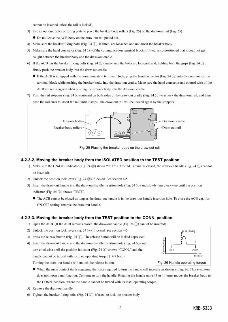
4) Insert the draw-out handle into the draw-out handle insertion hole (Fig. 24 4 ) and
turn clockwise until the position indicator (Fig. 24 5 ) shows “CONN.” and the
handle cannot be turned with its max. operating torque (14.7 N-m).
Turning the draw-out handle will unlock the release button. Fig. 26 Handle operating torque
When the main contact starts engaging, the force required to turn the handle will increase as shown in Fig. 26. This symptom
does not mean a malfunction. Continue to turn the handle. Rotating the handle more 13 or 14 turns moves the breaker body to
the CONN. position, where the handle cannot be turned with its max. operating torque.
5) Remove the draw-out handle.
6) Tighten the breaker fixing bolts (Fig. 24 2 ), if used, to lock the breaker body.
Breaker body
Breaker body rollers
Draw-out cradle
Draw-out rail
13 or 14 turns
TEST CONN.
Ope
ratin
g to
rque
Position
KRB-5333 34
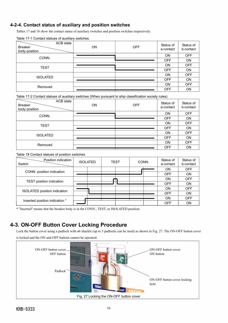
4-2-4. Contact status of auxiliary and position switchesTables 17 and 18 show the contact status of auxiliary switches and position switches respectively.
Table 17-1 Contact statues of auxiliary switchesACB state
Breakerbody position
ON OFF Status ofa-contact
Status ofb-contact
ON OFFCONN.
OFF ONON OFF
TESTOFF ONON OFF
ISOLATEDOFF ONON OFF
RemovedOFF ON
Table 17-2 Contact statues of auxiliary switches (When pursuant to ship classification society rules)ACB state
Breakerbody position
ON OFF Status ofa-contact
Status ofb-contact
ON OFFCONN.
OFF ONON OFF
TESTOFF ONON OFF
ISOLATEDOFF ONON OFF
RemovedOFF ON
Table 18 Contact statues of position switchesPosition indication
Switch ISOLATED TEST CONN. Status ofa-contact
Status ofb-contact
ON OFFCONN. position indication
OFF ONON OFF
TEST position indicationOFF ONON OFF
ISOLATED position indicationOFF ONON OFF
Inserted position indication *OFF ON
* "Inserted" means that the breaker body is in the CONN., TEST, or ISOLATED position.
4-3. ON-OFF Button Cover Locking ProcedureLock the button cover using a padlock with ø6 shackle (up to 3 padlocks can be used) as shown in Fig. 27. The ON-OFF button cover
is locked and the ON and OFF buttons cannot be operated.
Fig. 27 Locking the ON-OFF button cover
ON-OFF button coverOFF button
Padlock
ON-OFF button coverON button
ON-OFF button cover lockinghole
KRB-533335
OFF button
OFF-lock tab
Button cover lockinghole
OFF button cover
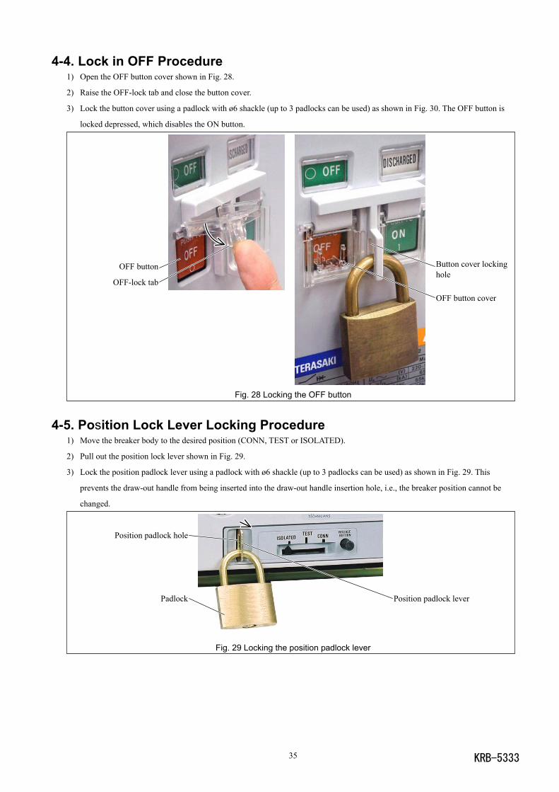
4-4. Lock in OFF Procedure1) Open the OFF button cover shown in Fig. 28.
2) Raise the OFF-lock tab and close the button cover.
3) Lock the button cover using a padlock with ø6 shackle (up to 3 padlocks can be used) as shown in Fig. 30. The OFF button is
locked depressed, which disables the ON button.
Fig. 28 Locking the OFF button
4-5. Position Lock Lever Locking Procedure1) Move the breaker body to the desired position (CONN, TEST or ISOLATED).
2) Pull out the position lock lever shown in Fig. 29.
3) Lock the position padlock lever using a padlock with ø6 shackle (up to 3 padlocks can be used) as shown in Fig. 29. This
prevents the draw-out handle from being inserted into the draw-out handle insertion hole, i.e., the breaker position cannot be
changed.
Fig. 29 Locking the position padlock lever
Position padlock lever
Position padlock hole
Padlock
KRB-5333 36
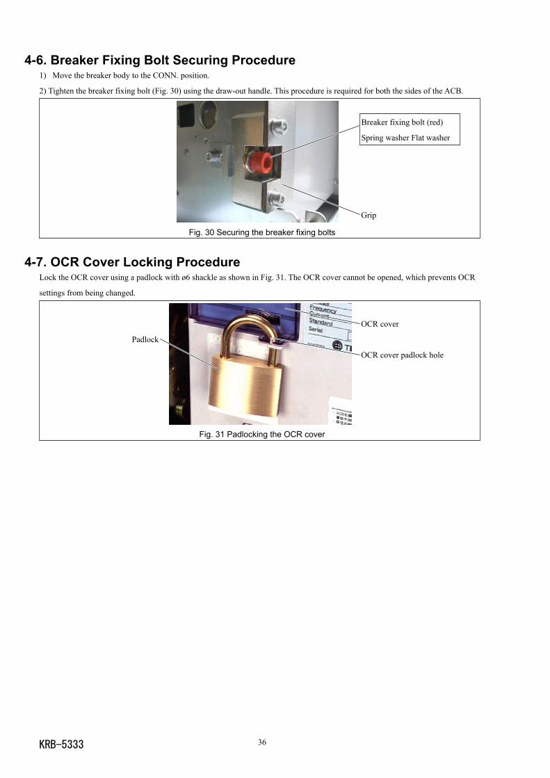
4-6. Breaker Fixing Bolt Securing Procedure1) Move the breaker body to the CONN. position.
2) Tighten the breaker fixing bolt (Fig. 30) using the draw-out handle. This procedure is required for both the sides of the ACB.
Fig. 30 Securing the breaker fixing bolts
4-7. OCR Cover Locking ProcedureLock the OCR cover using a padlock with ø6 shackle as shown in Fig. 31. The OCR cover cannot be opened, which prevents OCR
settings from being changed.
Fig. 31 Padlocking the OCR cover
OCR cover
OCR cover padlock hole
Padlock
Grip
Breaker fixing bolt (red)
Spring washer Flat washer
KRB-533337
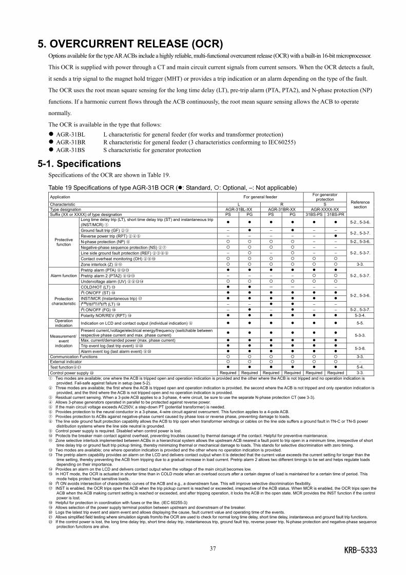
5. OVERCURRENT RELEASE (OCR)Options available for the type AR ACBs include a highly reliable, multi-functional overcurrent release (OCR) with a built-in 16-bit microprocessor.
This OCR is supplied with power through a CT and main circuit current signals from current sensors. When the OCR detects a fault,
it sends a trip signal to the magnet hold trigger (MHT) or provides a trip indication or an alarm depending on the type of the fault.
The OCR uses the root mean square sensing for the long time delay (LT), pre-trip alarm (PTA, PTA2), and N-phase protection (NP)
functions. If a harmonic current flows through the ACB continuously, the root mean square sensing allows the ACB to operate
normally.
The OCR is available in the type that follows: AGR-31BL L characteristic for general feeder (for works and transformer protection) AGR-31BR R characteristic for general feeder (3 characteristics conforming to IEC60255) AGR-31BS S characteristic for generator protection
5-1. SpecificationsSpecifications of the OCR are shown in Table 19.
Table 19 Specifications of type AGR-31B OCR ( : Standard, : Optional, –: Not applicable)Application For general feeder For generator
protectionCharacteristic L R SType designation AGR-31BL-XX AGR-31BR-XX AGR-XXXX-XXSuffix (XX or XXXX) of type designation PS PG PS PG 31BS-PS 31BS-PR
Referencesection
Long time delay trip (LT), short time delay trip (ST) and instantaneous trip(INST/MCR) 1 5-2., 5-3-6.
Ground fault trip (GF) 2 3 – – – –Reverse power trip (RPT) 2 4 5 – – – – –
5-2., 5-3-7.
N-phase protection (NP) 6 – – 5-2., 5-3-6.Negative-phase sequence protection (NS) 2 7 – –Line side ground fault protection (REF) 2 3 8 9 – – – –Contact overheat monitoring (OH) 2 9 10
5-2., 5-3-7.
Protectivefunction
Zone interlock (Z) 9 11 3-3.Pretrip alarm (PTA) 9 1213
Pretrip alarm 2 (PTA2) 9 1213 – – – –Alarm functionUndervoltage alarm (UV) 5 9 1214
5-2., 5-3-7.
COLD/HOT (LT) 15 - - – –I2t ON/OFF (ST) 16
INST/MCR (Instantaneous trip) 17
I0.02t/It/I2T/I3t/I4t (LT) 18 – – – –
5-2., 5-3-6.
I2t ON/OFF (FG) 16 – – – – 5-2., 5-3-7.
Protectioncharacteristic
Polarity NOR/REV (RPT) 19 5-3-4.Operationindication Indication on LCD and contact output (individual indication) 9 5-5.
Present current,/voltage/electrical energy/frequency (switchable betweenrespective phase current and max. phase current)Max. current/demanded power (max. phase current)
5-3-3.
Trip event log (last trip event) 9 20
Measurement/event
indicationAlarm event log (last alarm event) 9 20
5-3-8.
Communication Functions 3-3.External indicator –Test function9 21 5-4.Control power supply 22 Required Required Required Required Required Required 3-3.1 Two modes are available; one where the ACB is tripped open and operation indication is provided and the other where the ACB is not tripped and no operation indication is
provided. Fail-safe against failure in setup (see 5-2).2 Three modes are available; the first where the ACB is tripped open and operation indication is provided, the second where the ACB is not tripped and only operation indication is
provided, and the third where the ACB is not tripped open and no operation indication is provided.3 Residual current sensing. When a 3-pole ACB applies to a 3-phase, 4-wire circuit, be sure to use the separate N-phase protection CT (see 3-3).4 Allows 3-phase generators operated in parallel to be protected against reverse power.5 If the main circuit voltage exceeds AC250V, a step-down PT (potential transformer) is needed.6 Provides protection to the neural conductor in a 3-phase, 4-wire circuit against overcurrent. This function applies to a 4-pole ACB.7 Provides protection to ACBs against negative-phase current caused by phase loss or reverse phase, preventing damage to loads.8 The line side ground fault protection capability allows the ACB to trip open when transformer windings or cables on the line side suffers a ground fault in TN-C or TN-S power
distribution systems where the line side neutral is grounded.9 Control power supply is required. Disabled when control power is lost.10 Protects the breaker main contact against overheat, preventing troubles caused by thermal damage of the contact. Helpful for preventive maintenance.11 Zone selective interlock implemented between ACBs in a hierarchical system allows the upstream ACB nearest a fault point to trip open in a minimum time, irrespective of short
time delay trip or ground fault trip pickup timing, thereby minimizing thermal or mechanical damage to loads. This stands for selective discrimination with zero timing.12 Two modes are available; one where operation indication is provided and the other where no operation indication is provided.13 The pretrip alarm capability provides an alarm on the LCD and delivers contact output when it is detected that the current value exceeds the current setting for longer than the
time setting, thereby preventing the ACB from tripping due to a gradual increase in load current. Pretrip alarm 2 allows two different timings to be set and helps regulate loadsdepending on their importance.
14 Provides an alarm on the LCD and delivers contact output when the voltage of the main circuit becomes low.15 In HOT mode, the OCR is actuated in shorter time than in COLD mode when an overload occurs after a certain degree of load is maintained for a certain time of period. This
mode helps protect heat sensitive loads.16 I2t ON avoids intersection of characteristic curves of the ACB and e.g., a downstream fuse. This will improve selective discrimination flexibility.17 INST is enabled, the OCR trips open the ACB when the trip pickup current is reached or exceeded, irrespective of the ACB status. When MCR is enabled, the OCR trips open the
ACB when the ACB making current setting is reached or exceeded, and after tripping operation, it locks the ACB in the open state. MCR provides the INST function if the controlpower is lost.
18 Helpful for protection in coordination with fuses or the like. (IEC 60255-3)19 Allows selection of the power supply terminal position between upstream and downstream of the breaker.20 Logs the latest trip event and alarm event and allows displaying the cause, fault current value and operating time of the events.21 Allows simplified field testing where simulation signals from/to the OCR are used to check for normal long time delay, short time delay, instantaneous and ground fault trip functions.22 If the control power is lost, the long time delay trip, short time delay trip, instantaneous trip, ground fault trip, reverse power trip, N-phase protection and negative-phase sequence
protection functions are alive.
KRB-5333 38
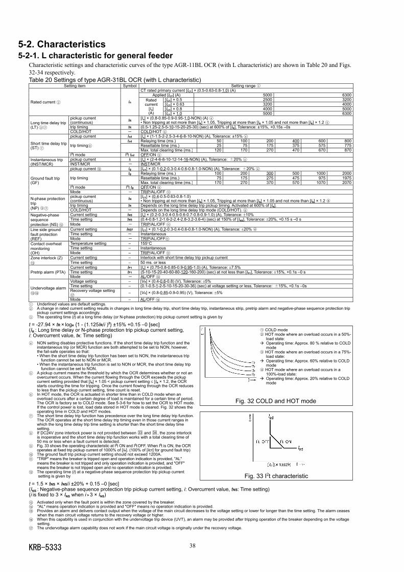
5-2. Characteristics5-2-1. L characteristic for general feeder
Characteristic settings and characteristic curves of the type AGR-11BL OCR (with L characteristic) are shown in Table 20 and Figs.32-34 respectively.Table 20 Settings of type AGR-31BL OCR (with L characteristic)
Setting item Symbol Setting range 1CT rated primary current [ICT] × (0.5-0.63-0.8-1.0) (A)
Applied [ICT] (A) 5000 6300[ICT] × 0.5 2500 3200[ICT] × 0.63 3200 4000[ICT] × 0.8 4000 5000
Rated current 2 In Ratedcurrent
[In](A) [ICT] × 1.0 5000 6300
pickup current(continuous) IR [In] × (0.8-0.85-0.9-0.95-1.0-NON) (A) 4
• Non tripping at not more than [IR] × 1.05, Tripping at more than [IR × 1.05 and not more than [IR] × 1.2 5trip timing tR (0.5-1.25-2.5-5-10-15-20-25-30) (sec) at 600% of [IR], Tolerance: ±15%, +0.15s –0s
Long time delay trip(LT) 3 7
COLD/HOT - COLD/HOT 6pickup current Isd [In] × (1-1.5-2-2.5-3-4-6-8-10-NON) (A), Tolerance: ±15% 4
tsd Relaying time (ms.) 50 100 200 400 600 800Resettable time (ms.) 25 75 175 375 575 775trip timing8Max. total clearing time (ms.) 120 170 270 470 670 870
Short time delay trip(ST) 7
I2t mode I2t tsd OFF/ON 9pickup current Ii [In] × (2-4-6-8-10-12-14-16-NON) (A), Tolerance: ±20% 4Instantaneous trip
(INST/MCR) INST/MCR - INST/MCRpickup current 10 Ig [ICT] × (0.1-0.2-0.3-0.4-0.6-0.8-1.0-NON) (A), Tolerance: ±20% 4
tg Relaying time (ms.) 100 200 300 500 1000 2000Resettable time (ms.) 75 175 275 475 975 1975trip timingMax. total clearing time (ms.) 170 270 370 570 1070 2070
I2t mode I2t tg OFF/ON 9
Ground fault trip(GF)
Mode - TRIP/AL/OFF 11pickup current(continuous) IN [ICT] × (0.4-0.5-0.63-0.8-1.0)
• Non tripping at not more than [IN] × 1.05, Tripping at more than [IN] × 1.05 and not more than [IN] × 1.2 5trip timing tR Depends on the long time delay trip pickup timing. Activated at 600% of [IN].
N-phase protectiontrip(NP) 3 7 COLD/HOT - Depends on the long time delay trip mode (COLD/HOT). 6
Current setting INS [In] × (0.2-0.3-0.4-0.5-0.6-0.7-0.8-0.9-1.0) (A), Tolerance: ±10%Time setting tNS (0.4-0.8-1.2-1.6-2-2.4-2.8-3.2-3.6-4) (sec) at 150% of [INS], Tolerance: ±20%, +0.15 s –0 s
Negative-phasesequenceprotection (NS) 12 Mode - TRIP/AL/OFF 11
Current setting IREF [ICT] × (0.1-0.2-0.3-0.4-0.6-0.8-1.0-NON) (A), Tolerance: ±20% 4Time setting - Instantaneous
Line side groundfault protection(REF) Mode - TRIP/AL/OFF11
Temperature setting – 155°CTime setting – Instantaneous
Contact overheatmonitoring(OH) Mode – TRIP/AL/OFF 11
Current setting – Interlock with short time delay trip pickup currentZone interlock (Z)13 Time setting – 50 ms. or less
Current setting IP1 [In] × (0.75-0.8-0.85-0.9-0.95-1.0) (A), Tolerance: ±7.5%Time setting tP1 (5-10-15-20-40-60-80-120-160-200) (sec) at not less than [IP1], Tolerance: ±15%, +0.1s –0 sPretrip alarm (PTA)Mode - AL/OFF 14Voltage setting – [Vn] × (0.4-0.6-0.8) (V), Tolerance: ±5%Time setting – (0.1-0.5-1-2-5-10-15-20-30-36) (sec) at voltage setting or less, Tolerance: ±15%, +0.1s –0sRecovery voltage setting17
– [Vn] × (0.8-0.85-0.9-0.95) (V), Tolerance: ±5%Undervoltage alarm15 16
Mode – AL/OFF 14
1 Underlined values are default settings.2 A change in rated current setting results in changes in long time delay trip, short time delay trip, instantaneous strip, pretrip alarm and negative-phase sequence protection trip
pickup current settings accordingly.3 The operating time (t) at a long time delay (or N-phase protection) trip pickup current setting is given by
t = -27.94 × tR × loge 1 - (1.125IR/i )2 ±15% +0.15 –0 [sec](IR : Long time delay or N-phase protection trip pickup current setting,i: Overcurrent value, tR: Time setting)4 NON setting disables protective functions. If the short time delay trip function and the
instantaneous trip (or MCR) function are both attempted to be set to NON, however,the fail-safe operates so that:• When the short time delay trip function has been set to NON, the instantaneous trip
function cannot be set to NON or MCR.• When the instantaneous trip function is set to NON or MCR, the short time delay trip
function cannot be set to NON.5 A pickup current means the threshold by which the OCR determines whether or not an
overcurrent occurs. When the current flowing through the OCR exceeds the pickupcurrent setting provided that [IR] × 1.05 < pickup current setting ≤ [IR × 1.2, the OCRstarts counting the time for tripping. Once the current flowing through the OCR reducesto less than the pickup current setting, time count is reset.
6 In HOT mode, the OCR is actuated in shorter time than in COLD mode when anoverload occurs after a certain degree of load is maintained for a certain time of period.The OCR is factory se to COLD mode. See 5-3-6 for how to set the OCR to HOT mode.If the control power is lost, load data stored in HOT mode is cleared. Fig. 32 shows theoperating time in COLD and HOT modes.
7 The short time delay trip function has precedence over the long time delay trip function.The OCR operates at the short time delay trip timing even in those current ranges inwhich the long time delay trip time setting is shorter than the short time delay timesetting.
8 If DC24V zone interlock power is not provided between 33 and 34 , the zone interlockis inoperative and the short time delay trip function works with a total clearing time of50 ms or less when a fault current is detected.
9 Fig. 33 shows the operating characteristic at I2t ON and I2t OFF. When I2t is ON, the OCRoperates at fixed trip pickup current of 1000% of [In]. (100% of [ICT] for ground fault trip)
10 The ground fault trip pickup current setting should not exceed 1200A.11 "TRIP" means the breaker is tripped open and operation indication is provided, "AL"
means the breaker is not tripped and only operation indication is provided, and "OFF"means the breaker is not tripped open and no operation indication is provided.
12 The operating time (t) at a negative-phase sequence protection trip pickup currentsetting is given by
t = 1.5 × tNS × INS/i ±20% + 0.15 –0 [sec](INS : Negative-phase sequence protection trip pickup current setting, i: Overcurrent value, tNS: Time setting)(i is fixed to 3 × INS when i > 3 × INS)13 Activated only when the fault point is within the zone covered by the breaker.14 "AL" means operation indication is provided and "OFF" means no operation indication is provided.15 Provides an alarm and delivers contact output when the voltage of the main circuit decreases to the voltage setting or lower for longer than the time setting. The alarm ceases
when the main circuit voltage returns to the recovery voltage or higher.16 When this capability is used in conjunction with the undervoltage trip device (UVT), an alarm may be provided after tripping operation of the breaker depending on the voltage
setting.17 The undervoltage alarm capability does not work if the main circuit voltage is originally under the recovery voltage.
Fig. 33 I2t characteristic
1 COLD mode2 HOT mode where an overload occurs in a 50%-
load state:Operating time: Approx. 80 % relative to COLDmode
3 HOT mode where an overload occurs in a 75%-load state:
Operating time: Approx. 60% relative to COLDmode
4 HOT mode where an overload occurs in a100%-load state:
Operating time: Approx. 20% relative to COLDmode
Fig. 32 COLD and HOT mode
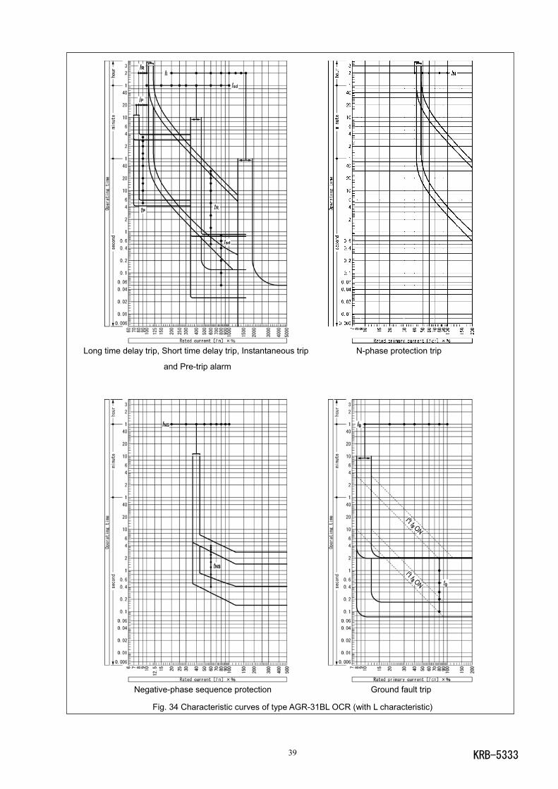
KRB-533339
Long time delay trip, Short time delay trip, Instantaneous trip N-phase protection trip
and Pre-trip alarm
Negative-phase sequence protection Ground fault trip
Fig. 34 Characteristic curves of type AGR-31BL OCR (with L characteristic)
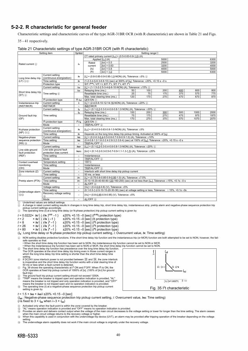
KRB-5333 40
5-2-2. R characteristic for general feederCharacteristic settings and characteristic curves of the type AGR-31BR OCR (with R characteristic) are shown in Table 21 and Figs.
35 - 41 respectively.
Table 21 Characteristic settings of type AGR-31BR OCR (with R characteristic)Setting item Symbol Setting range1
CT rated primary current [ICT] × (0.5-0.63-0.8-1.0) (A)Applied [ICT] (A) 5000 6300
[ICT] × 0.5 2500 3200[ICT] × 0.63 3200 4000[ICT] × 0.8 4000 5000
Rated current 2 In Ratedcurrent
[In](A) [ICT] × 1.0 5000 6300
Current setting(continuous energization) IR [In] × (0.8-0.85-0.9-0.95-1.0-NON) (A), Tolerance: ±5% 4
Time setting tR (1-2-3-4-5-6.3-6.8-10) (sec) at 300% of [IR], Tolerance: ±20%, +0.15 s –0 sLong time delay trip(LT) 3 5
Protection type – SIT: I0.02 t, VIT: I t, EIT: I2 t, 3IT: I3 t, 4IT: I4 tCurrent setting Isd [In] × (1-1.5-2-2.5-3-4-6-8-10-NON) (A), Tolerance: ±15% 4
tsd Relaying time (ms.) 50 100 200 400 600 800Resettable time (ms.) 25 75 175 375 575 775Time setting 6
Max. total clearing time (ms.) 120 170 270 470 670 870
Short time delay trip(ST) 5
I2t protection type I2t tsd OFF/ON 7
Current setting Ii [In] × (2-4-6-8-10-12-14-16-NON) (A), Tolerance: ±20% 4Instantaneous trip(INST/MCR) INST/MCR – INST/MCR
Current setting 8 Ig [ICT] × (0.1-0.2-0.3-0.4-0.6-0.8-1.0-NON) (A), Tolerance: ±20% 4
tg Relaying time (ms.) 100 200 300 500 1000 2000Resettable time (ms.) 75 175 275 475 975 1975Time settingMax. total clearing time (ms.) 170 270 370 570 1070 2070
I2t protection type I2t tg OFF/ON 7
Ground fault trip(GF)
Mode – TRIP/AL/OFF 9
Current setting(continuous energization) IN [ICT] × (0.4-0.5-0.63-0.8-1.0-NON) (A), Tolerance: ±5%N-phase protection
(NP) 3 5 Time setting tR Depends on the long time delay trip pickup timing. Activated at 300% of [IN].Current setting INS [In] × (0.2-0.3-0.4-0.5-0.6-0.7-0.8-0.9-1.0) (A), Tolerance: ±10%Time setting tNS (0.4-0.8-1.2-1.6-2-2.4-2.8-3.2-3.6-4) (sec) at 150% of [INS], Tolerance: ±20%, +0.15 s –0 s
Negative-phasesequence protection(NS) 10 Mode – TRIP/AL/OFF 9
Current setting IREF [ICT] × (0.1-0.2-0.3-0.4-0.6-0.8-1.0-NON) (A), Tolerance: ±20% 4
Line side ground faultprotection bias current IREF2 [ICT] × (0.1-0.2-0.3-0.5-0.7-0.9-1.1-1.3-1.5) (A), Tolerance: ±20%
Time setting – Instantaneous
Line side groundfault protection(REF)
Mode – TRIP/AL/OFF 9
Temperature setting – 155°CTime setting – Instantaneous
Contact overheatmonitoring(OH) Mode – TRIP/AL/OFF 9
Current setting – Interlock with short time delay trip pickup currentZone interlock (Z)11 Time setting – 50 ms. or less
Current setting IP1 [In] × (0.75-0.8-0.85-0.9-0.95-1.0) (A), Tolerance: ±7.5%Time setting tP1 (5-10-15-20-40-60-80-120-160-200) (sec) at not less than [IP1], Tolerance: ±15%, +0.1s –0 sPretrip alarm (PTA)Mode – AL/OFF 12
Voltage setting – [Vn] × (0.4-0.6-0.8) (V), Tolerance: ±5%Time setting – (0.1-0.5-1-2-5-10-15-20-30-36) (sec) at voltage setting or less, Tolerance: ±15%, +0.1s –0sRecovery voltage setting15
– [Vn] × (0.8-0.85-0.9-0.95) (V), Tolerance: ±5%Undervoltage alarm13 14
Mode – AL/OFF 12
1 Underlined values are default settings.2 A change in rated current setting results in changes in long time delay trip, short time delay trip, instantaneous strip, pretrip alarm and negative-phase sequence protection trip
pickup current settings accordingly.3 The operating time (t) at a long time delay (or N-phase protection) trip pickup current setting is given by
t = 0.0222× tR/ ( i/IR )0.02 –1 ±20% +0.15 –0 [sec] (I0.02t protection type)t = 2 × tR/ ( i/IR ) –1 ±20% +0.15 –0 [sec] (It protection type)t = 8 × tR/ ( i/IR )2 –1 ±20% +0.15 –0 [sec] (I2t protection type)t = 26 × tR/ ( i/IR )3 –1 ±20% +0.15 –0 [sec] (I3t protection type)t = 80 × tR/ ( i/IR )4 –1 ±20% +0.15 –0 [sec] (I4t protection type)(IR : Long time delay or N-phase protection trip pickup current setting, i: Overcurrent value, tR: Time setting)4 NON setting disables protective functions. If the short time delay trip function and the instantaneous trip (or MCR) function are both attempted to be set to NON, however, the fail-
safe operates so that:• When the short time delay trip function has been set to NON, the instantaneous trip function cannot be set to NON or MCR.• When the instantaneous trip function has been set to NON or MCR, the short time delay trip function cannot be set to NON.
5 The short time delay trip function has precedence over the long time delay trip function.The OCR operates at the short time delay trip timing even in those current ranges inwhich the long time delay trip time setting is shorter than the short time delay timesetting.
6 If DC24V zone interlock power is not provided between 33 and 34 , the zone interlockis inoperative and the short time delay trip function works with a total clearing time of50 ms or less when a fault current is detected.
7 Fig. 39 shows the operating characteristic at I2 ON and I2 OFF. When I2t is ON, theOCR operates at fixed trip pickup current of 1000% of [In]. (100% of [ICT] for groundfault trip)
8 The ground fault trip pickup current setting should not exceed 1200A.9 "TRIP" means the breaker is tripped open and operation indication is provided, "AL"
means the breaker is not tripped and only operation indication is provided, and "OFF"means the breaker is not tripped open and no operation indication is provided.
10 The operating time (t) at a negative-phase sequence protection trip pickup currentsetting is given by
t = 1.5 × tNS × INS/i ±20% +0.15 –0 [sec](INS : Negative-phase sequence protection trip pickup current setting, i: Overcurrent value, tNS: Time setting)(i is fixed to 3 × INS when i > 3 × INS)11 Activated only when the fault point is within the zone covered by the breaker.12 "AL" means operation indication is provided and "OFF" means no operation indication is provided.13 Provides an alarm and delivers contact output when the voltage of the main circuit decreases to the voltage setting or lower for longer than the time setting. The alarm ceases
when the main circuit voltage returns to the recovery voltage or higher.14 When this capability is used in conjunction with the undervoltage trip device (UVT), an alarm may be provided after tripping operation of the breaker depending on the voltage
setting.15 The undervoltage alarm capability does not work if the main circuit voltage is originally under the recovery voltage.
Fig. 35 I2t characteristic
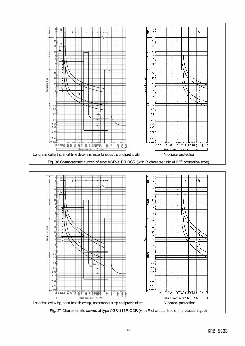
KRB-533341
Long time delay trip, short time delay trip, instantaneous trip and pretrip alarm N-phase protection
Fig. 36 Characteristic curves of type AGR-31BR OCR (with R characteristic of I0.02t protection type)
Long time delay trip, short time delay trip, instantaneous trip and pretrip alarm N-phase protection
Fig. 37 Characteristic curves of type AGR-31BR OCR (with R characteristic of It protection type)
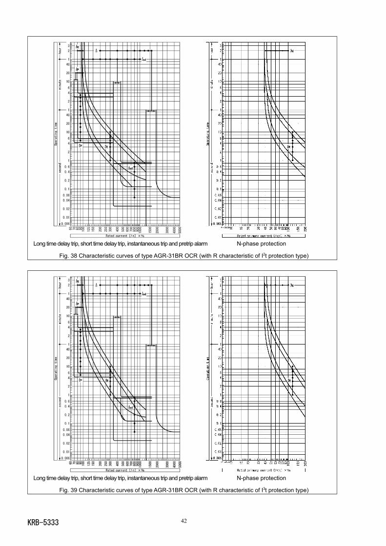
KRB-5333 42
Long time delay trip, short time delay trip, instantaneous trip and pretrip alarm N-phase protection
Fig. 38 Characteristic curves of type AGR-31BR OCR (with R characteristic of I2t protection type)
Long time delay trip, short time delay trip, instantaneous trip and pretrip alarm N-phase protection
Fig. 39 Characteristic curves of type AGR-31BR OCR (with R characteristic of I3t protection type)
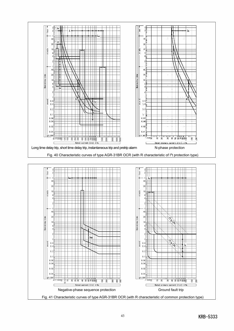
KRB-533343
Long time delay trip, short time delay trip, instantaneous trip and pretrip alarm N-phase protection
Fig. 40 Characteristic curves of type AGR-31BR OCR (with R characteristic of I4t protection type)
Negative-phase sequence protection Ground fault trip
Fig. 41 Characteristic curves of type AGR-31BR OCR (with R characteristic of common protection type)
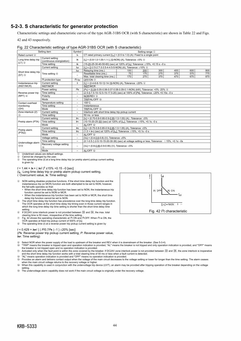
KRB-5333 44
5-2-3. S characteristic for generator protectionCharacteristic settings and characteristic curves of the type AGR-31BS OCR (with S characteristic) are shown in Table 22 and Figs.
42 and 43 respectively.
Fig. 22 Characteristic settings of type AGR-31BS OCR (with S characteristic)Setting item Symbol Setting range 1
Rated current 2 In CT rated primary current [ICT] × (0.5 to 1.0) (A): Fixed to a single pointCurrent setting(continuous energization) IR [In] × (0.8-1.0-1.05-1.1-1.15-NON) (A), Tolerance: ±5% 4Long time delay trip
(LT) 3 Time setting tR (15-20-25-30-40-50-60) (sec) at 120% of [IR], Tolerance: ±15%, +0.15 s –0 sCurrent setting Isd [In] x (2-2.5-2.7-3-3.5-4-4.5-5-NON) (A), Tolerance: ±10% 4
tsd Relaying time (ms.) 100 200 300 400 600 800Resettable time (ms.) 75 175 275 375 575 775Time setting 6 – Max. total clearing time (ms.) 170 270 370 470 670 870
Short time delay trip(ST) 5
I2t protection type I2t tsd OFF/ON 7Current setting Ii [In] × (2-4-6-8-10-12-14-16-NON) (A), Tolerance: ±20% 4Instantaneous trip
(INST/MCR) INST/MCR INST/MCRPower setting PR [Pn] × (0.04-0.05-0.06-0.07-0.08-0.09-0.1-NON) (kW), Tolerance: +0% -20% 4Time setting – (2.5-5-7.5-10-12.5-15-17.5-20) (sec) at 100% of [PR], Tolerance: ±20% +0.15s –0 sPolarity – NOR/REV 9
Reverse power trip(RPT) 8
Mode – TRIP/AL/OFF 10
Temperature setting – 155°CTime setting – Instantaneous
Contact overheatmonitoring(OH) Mode – TRIP/AL/OFF 10
Current setting – Interlock with short time delay trip pickup currentZone interlock (Z)11 Time setting – 50 ms. or less
Current setting IP1 [In] × (0.75-0.8-0.85-0.9-0.95-1.0-1.05) (A) , Tolerance: ±5%Time setting tP1 (10-15-20-25-30) (sec) at 120% of [IP1], Tolerance: ±15%, +0.1s –0 sPretrip alarm (PTA)Mode – AL/OFF 12
Current setting IP2 [In] × (0.75-0.8-0.85-0.9-0.95-1.0-1.05) (A), Tolerance: ±5%Time setting tP2 (1.5 × tP1) (sec) at 120% of [IP2], Tolerance: ±15%, +0.1s –0 sPretrip alarm
(PTA2)Mode – AL/OFF 12
Voltage setting – [Vn] × (0.4-0.6-0.8) (V), Tolerance: ±5%Time setting – (0.1-0.5-1-2-5-10-15-20-30-36) (sec) at voltage setting or less, Tolerance: ±15%, +0.1s –0sRecovery voltage setting15
– [Vn] × (0.8-0.85-0.9-0.95) (V), Tolerance: ±5%Undervoltage alarm1314
Mode – AL/OFF 12
1 Underlined values are default settings.2 Cannot be changed by the user.3 The operating time (t) at a long time delay trip (or pretrip alarm) pickup current setting
is given by
t = 1.44 × tR × ( IR/i )2 ±15% +0.15 –0 [sec](IR : Long time delay trip or pretrip alarm pickup current setting,i: Overcurrent value, tR: Time setting)
4 NON setting disables protective functions. If the short time delay trip function and theinstantaneous trip (or MCR) function are both attempted to be set to NON, however,the fail-safe operates so that:• When the short time delay trip function has been set to NON, the instantaneous trip
function cannot be set to NON or MCR.• When the instantaneous trip function has been set to NON or MCR, the short time
delay trip function cannot be set to NON.5 The short time delay trip function has precedence over the long time delay trip function.
The OCR operates at the short time delay trip timing even in those current ranges inwhich the long time delay trip time setting is shorter than the short time delay timesetting.
6 If DC24V zone interlock power is not provided between 33 and 34 , the max. totalclearing time is 50 msec, irrespective of the time setting.
7 Fig. 42 shows the operating characteristic at I2t ON and I2t OFF. When I2t is ON, theOCR operates at fixed trip pickup current of 500% of [In].
8 The operating time (t) at a reverse power trip pickup current setting is given by
t = 0.429 × tRP/ ( P/0.7PR ) -1 ±20% [sec](PR: Reverse power trip pickup current setting, P: Reverse power value,tRP: Time setting)
9 Select NOR when the power supply of the load is upstream of the breaker and REV when it is downstream of the breaker. (See 5-3-4).10 "TRIP" means the breaker is tripped open and operation indication is provided, "AL" means the breaker is not tripped and only operation indication is provided, and "OFF" means
the breaker is not tripped open and no operation indication is provided.11 Activated only when the fault point is within the zone covered by the breaker. If DC24V zone interlock power is not provided between 33 and 34 , the zone interlock is inoperative
and the short time delay trip function works with a total clearing time of 50 ms or less when a fault current is detected.12 "AL" means operation indication is provided and "OFF" means no operation indication is provided.13 Provides an alarm and delivers contact output when the voltage of the main circuit decreases to the voltage setting or lower for longer than the time setting. The alarm ceases
when the main circuit voltage returns to the recovery voltage or higher.14 When this capability is used in conjunction with the undervoltage trip device (UVT), an alarm may be provided after tripping operation of the breaker depending on the voltage
setting.15 The undervoltage alarm capability does not work if the main circuit voltage is originally under the recovery voltage.
Fig. 42 I2t characteristic
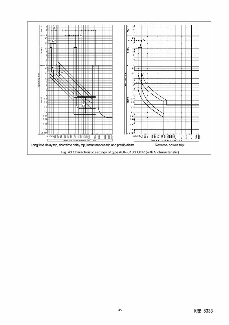
KRB-533345
Long time delay trip, short time delay trip, instantaneous trip and pretrip alarm Reverse power trip
Fig. 43 Characteristic settings of type AGR-31BS OCR (with S characteristic)
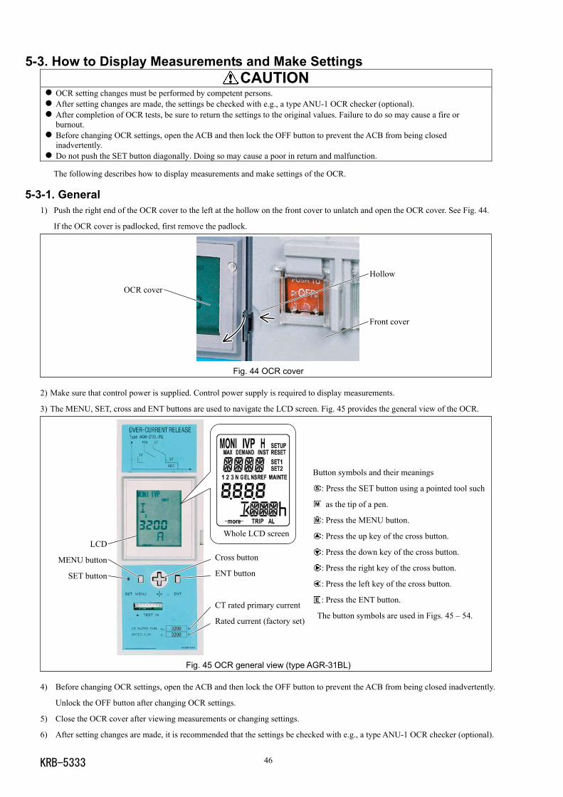
KRB-5333 46
5-3. How to Display Measurements and Make Settings CAUTION
OCR setting changes must be performed by competent persons. After setting changes are made, the settings be checked with e.g., a type ANU-1 OCR checker (optional). After completion of OCR tests, be sure to return the settings to the original values. Failure to do so may cause a fire orburnout.
Before changing OCR settings, open the ACB and then lock the OFF button to prevent the ACB from being closedinadvertently.
Do not push the SET button diagonally. Doing so may cause a poor in return and malfunction.
The following describes how to display measurements and make settings of the OCR.
5-3-1. General1) Push the right end of the OCR cover to the left at the hollow on the front cover to unlatch and open the OCR cover. See Fig. 44.
If the OCR cover is padlocked, first remove the padlock.
Fig. 44 OCR cover
2) Make sure that control power is supplied. Control power supply is required to display measurements.
3) The MENU, SET, cross and ENT buttons are used to navigate the LCD screen. Fig. 45 provides the general view of the OCR.
Button symbols and their meanings
: Press the SET button using a pointed tool such
as the tip of a pen.
: Press the MENU button.
: Press the up key of the cross button.
: Press the down key of the cross button.
: Press the right key of the cross button.
: Press the left key of the cross button.
: Press the ENT button.
The button symbols are used in Figs. 45 – 54.
Fig. 45 OCR general view (type AGR-31BL)
4) Before changing OCR settings, open the ACB and then lock the OFF button to prevent the ACB from being closed inadvertently.
Unlock the OFF button after changing OCR settings.
5) Close the OCR cover after viewing measurements or changing settings.
6) After setting changes are made, it is recommended that the settings be checked with e.g., a type ANU-1 OCR checker (optional).
OCR cover
Hollow
Front cover
液晶画面の表示寿命は,一般的にコントラストが50%以下になる時間で定められ,週温25,湿度55%RHの条件の下で,約5.7年です。液晶画面が見にくくなった場合,OCR全体の交換を要します。OCRの交換については,弊社にお問合わせ下さい。
LCD
MENU button
SET button
Whole LCD screen
Cross button
ENT button
CT rated primary current
Rated current (factory set)

KRB-533347
5-3-2. Available screensThe type AGR-31B OCR has seven screens available as shown in Fig. 46 below. Press the MENU button to go to the next screen.
Monitor 1 screen (MONI): See 5-3-3.
This is the initial screen that appears when control power is turned on. Various current values can be
viewed on this screen.
Monitor 2 screen (MONI IVP): See 5-3-4.
Various current values, line voltage, phase voltage, power, demanded power, electrical energy, power
factor and frequency can be viewed on this screen.
Setup screen (SETUP): See 5-3-5.
This screen allows reviewing the rated voltage, CT rated primary current or other specifications and
changing settings.
Reset screen (RESET): See 5-3-6.
This screen allows clearing the measured max. current and the trip/alarm event log and resetting
trip/alarm operation indication.
Setting 1 screen (SET1): See 5-3-7.
This screen allows viewing settings relating to long time delay, short time delay, instantaneous and
ground fault trip capabilities and changing these settings.
Setting 2 screen (SET2): See 5-3-8.
This screen allows viewing settings relating to other capabilities than described above and changing
these settings.
Maintenance screen (MAINTE): See 5-3-9.
This screen allows viewing the trip/alarm event log.
Test screen (MAINTE): See 5-4.
This screen allows testing the long time delay, short time delay, instantaneous and ground fault trip
functions.
Fig. 46 Available screens
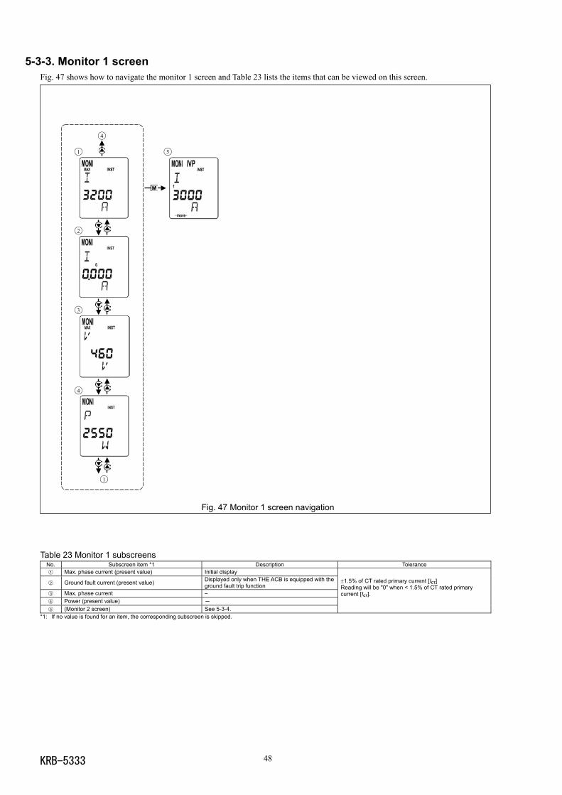
KRB-5333 48
4
1 5
2
3
4
1
5-3-3. Monitor 1 screenFig. 47 shows how to navigate the monitor 1 screen and Table 23 lists the items that can be viewed on this screen.
Fig. 47 Monitor 1 screen navigation
Table 23 Monitor 1 subscreensNo. Subscreen item *1 Description Tolerance1 Max. phase current (present value) Initial display
2 Ground fault current (present value) Displayed only when THE ACB is equipped with theground fault trip function
3 Max. phase current –4 Power (present value) -
5 (Monitor 2 screen) See 5-3-4.
±1.5% of CT rated primary current [ICT]Reading will be "0" when < 1.5% of CT rated primarycurrent [ICT].
*1: If no value is found for an item, the corresponding subscreen is skipped.
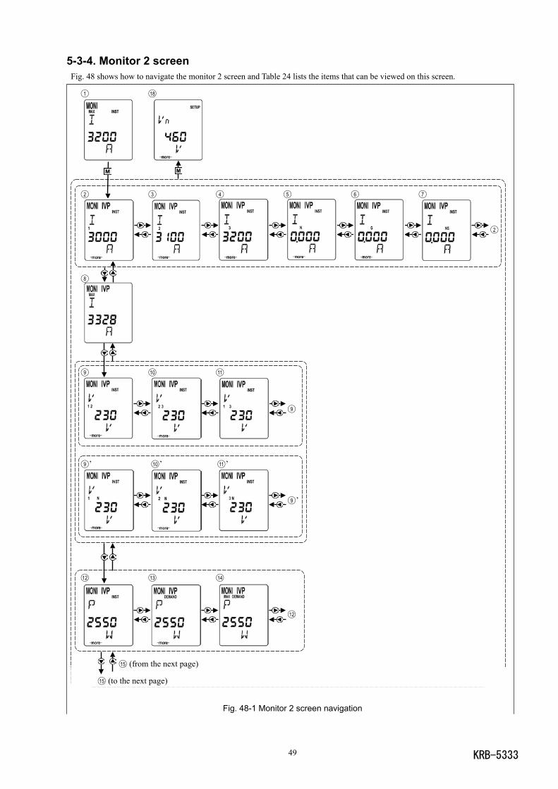
KRB-533349
1 18
2 3 4 5 6 7
2
8
9 10 11
9
9 ’ 10 ’ 11 ’
9 ’
12 13 14
12
15 (from the next page)
15 (to the next page)
5-3-4. Monitor 2 screen Fig. 48 shows how to navigate the monitor 2 screen and Table 24 lists the items that can be viewed on this screen.
Fig. 48-1 Monitor 2 screen navigation
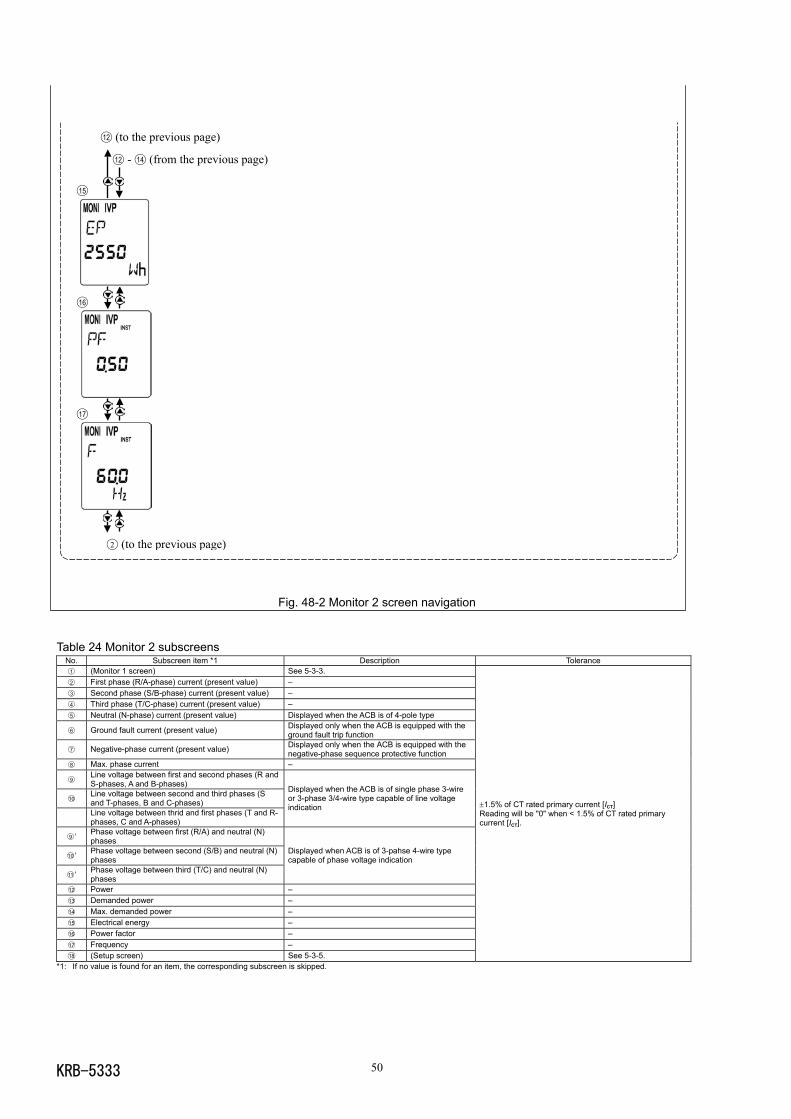
KRB-5333 50
Fig. 48-2 Monitor 2 screen navigation
Table 24 Monitor 2 subscreensNo. Subscreen item *1 Description Tolerance1 (Monitor 1 screen) See 5-3-3.2 First phase (R/A-phase) current (present value) –3 Second phase (S/B-phase) current (present value) –4 Third phase (T/C-phase) current (present value) –5 Neutral (N-phase) current (present value) Displayed when the ACB is of 4-pole type
6 Ground fault current (present value) Displayed only when the ACB is equipped with theground fault trip function
7 Negative-phase current (present value) Displayed only when the ACB is equipped with thenegative-phase sequence protective function
8 Max. phase current –
9Line voltage between first and second phases (R andS-phases, A and B-phases)
10Line voltage between second and third phases (Sand T-phases, B and C-phases)Line voltage between thrid and first phases (T and R-phases, C and A-phases)
Displayed when the ACB is of single phase 3-wireor 3-phase 3/4-wire type capable of line voltageindication
9 ’ Phase voltage between first (R/A) and neutral (N)phases
10 ’ Phase voltage between second (S/B) and neutral (N)phases
11 ’ Phase voltage between third (T/C) and neutral (N)phases
Displayed when ACB is of 3-pahse 4-wire typecapable of phase voltage indication
12 Power –13 Demanded power –14 Max. demanded power –15 Electrical energy –16 Power factor –17 Frequency –18 (Setup screen) See 5-3-5.
±1.5% of CT rated primary current [ICT]Reading will be "0" when < 1.5% of CT rated primarycurrent [ICT].
*1: If no value is found for an item, the corresponding subscreen is skipped.
12 (to the previous page)
12 - 14 (from the previous page)
15
16
17
2 (to the previous page)
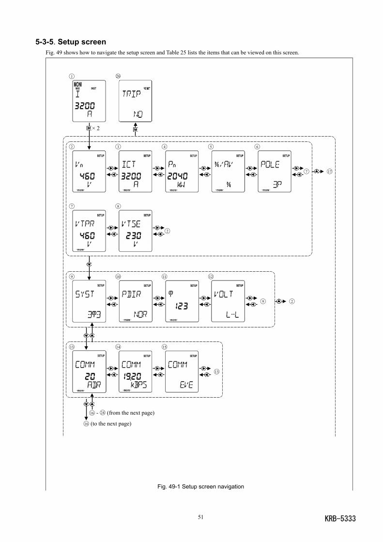
KRB-533351
5-3-5. Setup screenFig. 49 shows how to navigate the setup screen and Table 25 lists the items that can be viewed on this screen.
Fig. 49-1 Setup screen navigation
1 26
× 2
2 3 4 5 6
7 17
7 8
2
9 10 11 12
9 2
13 14 15
13
16 - 24 (from the next page)
16 (to the next page)
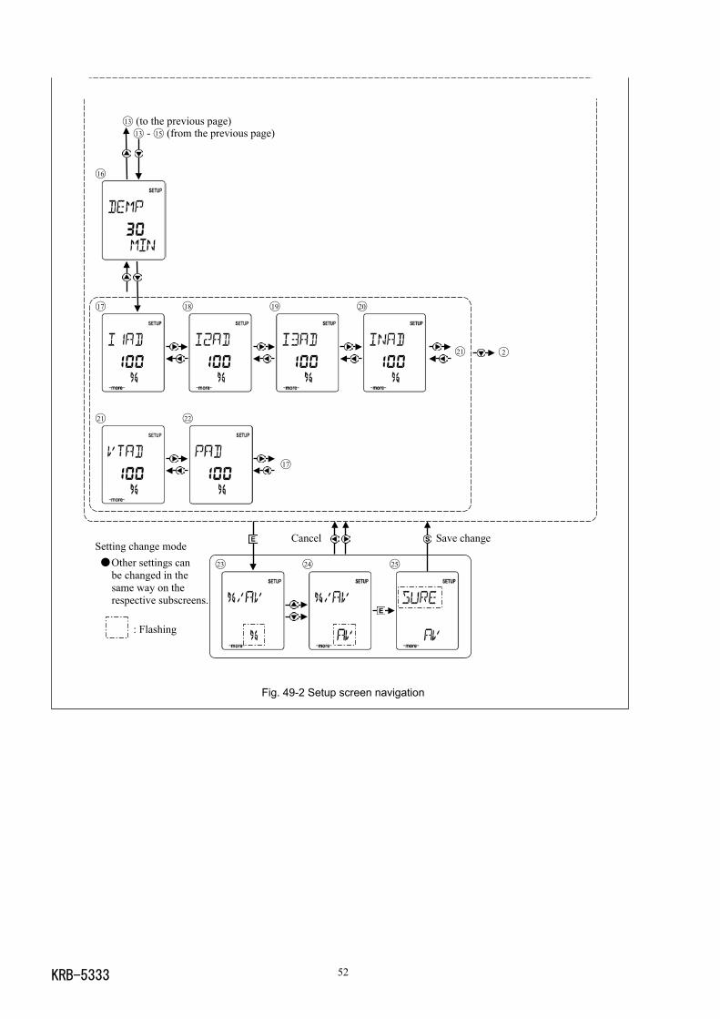
KRB-5333 52
Setting change mode Other settings can
be changed in thesame way on therespective subscreens.
: Flashing
Fig. 49-2 Setup screen navigation
13 (to the previous page)13 - 15 (from the previous page)
16
17 18 19 20
21 2
21 22
17
Cancel Save change
23 24 25
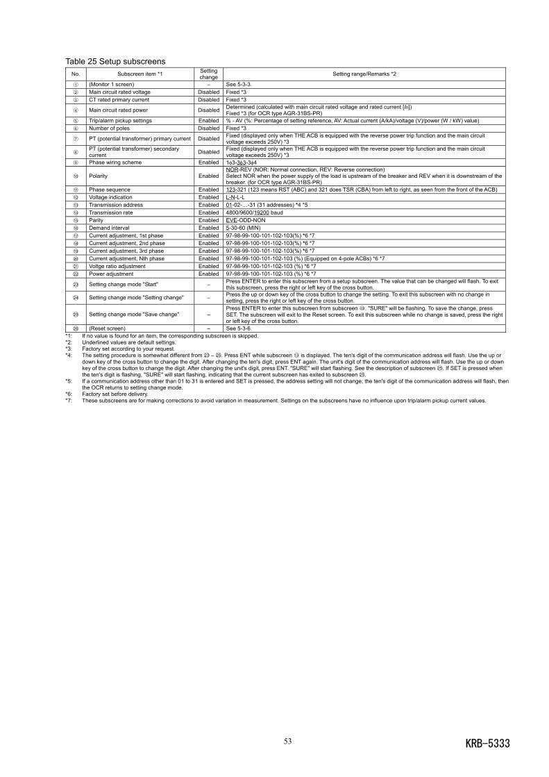
KRB-533353
Table 25 Setup subscreensNo. Subscreen item *1 Setting
change Setting range/Remarks *2
1 (Monitor 1 screen) – See 5-3-3.2 Main circuit rated voltage Disabled Fixed *33 CT rated primary current Disabled Fixed *3
4 Main circuit rated power Disabled Determined (calculated with main circuit rated voltage and rated current [In])Fixed *3 (for OCR type AGR-31BS-PR)
5 Trip/alarm pickup settings Enabled % - AV (%: Percentage of setting reference, AV: Actual current (A/kA)/voltage (V)/power (W / kW) value)6 Number of poles Disabled Fixed *3
7 PT (potential transformer) primary current Disabled Fixed (displayed only when THE ACB is equipped with the reverse power trip function and the main circuitvoltage exceeds 250V) *3
8PT (potential transformer) secondarycurrent Disabled Fixed (displayed only when THE ACB is equipped with the reverse power trip function and the main circuit
voltage exceeds 250V) *39 Phase wiring scheme Enabled 1φ3-3φ3-3φ4
10 Polarity EnabledNOR-REV (NOR: Normal connection, REV: Reverse connection)Select NOR when the power supply of the load is upstream of the breaker and REV when it is downstream of thebreaker. (for OCR type AGR-31BS-PR)
11 Phase sequence Enabled 123-321 (123 means RST (ABC) and 321 does TSR (CBA) from left to right, as seen from the front of the ACB)12 Voltage indication Enabled L-N-L-L13 Transmission address Enabled 01-02-…-31 (31 addresses) *4 *514 Transmission rate Enabled 4800/9600/19200 baud15 Parity Enabled EVE-ODD-NON16 Demand interval Enabled 5-30-60 (MIN)17 Current adjustment, 1st phase Enabled 97-98-99-100-101-102-103(%) *6 *718 Current adjustment, 2nd phase Enabled 97-98-99-100-101-102-103(%) *6 *719 Current adjustment, 3rd phase Enabled 97-98-99-100-101-102-103(%) *6 *720 Current adjustment, Nth phase Enabled 97-98-99-100-101-102-103 (%) (Equipped on 4-pole ACBs) *6 *721 Voltge ratio adjustment Enabled 97-98-99-100-101-102-103 (%) *6 *722 Power adjustment Enabled 97-98-99-100-101-102-103 (%) *6 *7
23 Setting change mode "Start" – Press ENTER to enter this subscreen from a setup subscreen. The value that can be changed will flash. To exitthis subscreen, press the right or left key of the cross button.
24 Setting change mode "Setting change" – Press the up or down key of the cross button to change the setting. To exit this subscreen with no change insetting, press the right or left key of the cross button.
25 Setting change mode "Save change" –Press ENTER to enter this subscreen from subscreen 19 . "SURE" will be flashing. To save the change, pressSET. The subscreen will exit to the Reset screen. To exit this subscreen while no change is saved, press the rightor left key of the cross button.
26 (Reset screen) – See 5-3-6.*1: If no value is found for an item, the corresponding subscreen is skipped.*2: Underlined values are default settings.*3: Factory set according to your request.*4: The setting procedure is somewhat different from 23 – 25. Press ENT while subscreen 13 is displayed. The ten's digit of the communication address will flash. Use the up or
down key of the cross button to change the digit. After changing the ten's digit, press ENT again. The unit's digit of the communication address will flash. Use the up or downkey of the cross button to change the digit. After changing the unit's digit, press ENT. "SURE" will start flashing. See the description of subscreen 25. If SET is pressed whenthe ten's digit is flashing, "SURE" will start flashing, indicating that the current subscreen has exited to subscreen 25.
*5: If a communication address other than 01 to 31 is entered and SET is pressed, the address setting will not change; the ten's digit of the communication address will flash, thenthe OCR returns to setting change mode.
*6: Factory set before delivery.*7: These subscreens are for making corrections to avoid variation in measurement. Settings on the subscreens have no influence upon trip/alarm pickup current values.
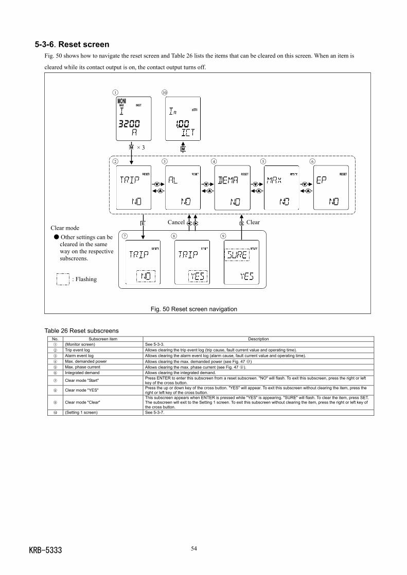
KRB-5333 54
5-3-6. Reset screenFig. 50 shows how to navigate the reset screen and Table 26 lists the items that can be cleared on this screen. When an item is
cleared while its contact output is on, the contact output turns off.
Clear mode Other settings can be
cleared in the sameway on the respectivesubscreens.
: Flashing
Fig. 50 Reset screen navigation
Table 26 Reset subscreensNo. Subscreen item Description1 (Monitor screen) See 5-3-3.2 Trip event log Allows clearing the trip event log (trip cause, fault current value and operating time).3 Alarm event log Allows clearing the alarm event log (alarm cause, fault current value and operating time).4 Max. demanded power Allows clearing the max. demanded power (see Fig. 47 17 )5 Max. phase current Allows clearing the max. phase current (see Fig. 47 9 ).6 Integrated demand Allows clearing the integrated demand.
7 Clear mode "Start" Press ENTER to enter this subscreen from a reset subscreen. "NO" will flash. To exit this subscreen, press the right or leftkey of the cross button.
8 Clear mode "YES" Press the up or down key of the cross button. "YES" will appear. To exit this subscreen without clearing the item, press theright or left key of the cross button.
9 Clear mode "Clear"This subscreen appears when ENTER is pressed while "YES" is appearing. "SURE" will flash. To clear the item, press SET.The subscreen will exit to the Setting 1 screen. To exit this subscreen without clearing the item, press the right or left key ofthe cross button.
10 (Setting 1 screen) See 5-3-7.
1 10
× 3
2 3 4 5 6
Cancel Clear
7 8 9
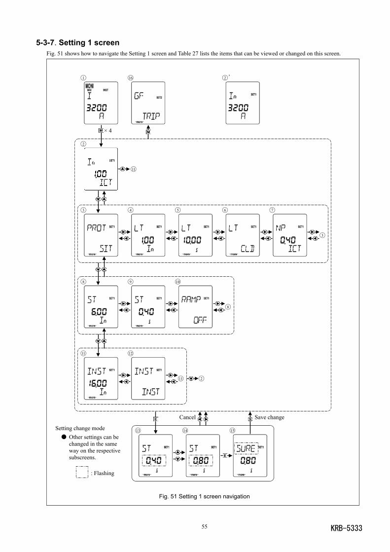
KRB-533355
5-3-7. Setting 1 screenFig. 51 shows how to navigate the Setting 1 screen and Table 27 lists the items that can be viewed or changed on this screen.
Setting change mode Other settings can be
changed in the sameway on the respectivesubscreens.
: Flashing
Fig. 51 Setting 1 screen navigation
1 16 2 ’
× 4
2
11
3 4 5 6 7
3
8 9 10
8
11 12
11 2
Cancel Save change
13 14 15
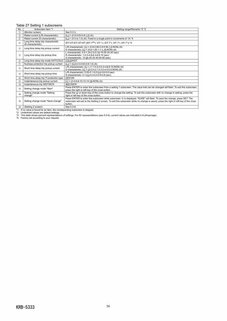
KRB-5333 56
Table 27 Setting 1 subscreensNo. Subscreen item *1 Setting range/Remarks *2 *31 (Monitor screen) See 5-3-3.2 Rated current (L/R characteristic) [ICT] × (0.5-0.63-0.8-1.0) (A)2 ’ Rated current (S characteristic) [ICT] × (0.5 to 1.0) (A): Fixed to a single point in increments of 1A *4
3Long time delay trip characteristic(R characteristic) SIT-VIT-EIT-3IT-4IT (SIT: I0.02 t, VIT: I t, EIT: I2 t, 3IT: I3 t, 4IT: I4 t) *4
4 Long time delay trip pickup current L/R characteristic: [In] × (0.8-0.85-0.9-0.95-1.0-NON) (A)S characteristic: [In] × (0.8-1.05-1.1-1.15-NON) (A)
5 Long time delay trip pickup timeL characteristic: 0.5-1.25-2.5-5-10-15-20-25-30 (sec)R characteristic: 1-2-3-4-5-6.3-6.8-10 (sec)S characteristic: 15-20-25-30-40-50-60 (sec)
6 Long time delay trip mode HOT/COLD COLD/HOT7 N-phase protection trip pickup current [ICT] × (0.4-0.5-0.63-0.8-1.0) (A)
8 Short time delay trip pickup current L/R characteristic: [In] × (1-1.5-2-2.5-3-4-6-8-10-NON) (A)S characteristic: [In] × (2-2.5-2.7-3-3.5-4-4.5-5-NON) (A)
9 Short time delay trip pickup time L/R characteristic: 0.05-0.1-0.2-0.4-0.6-0.8 (sec)S characteristic: 0.1-0.2-0.3-0.4-0.6-0.8 (sec)
10 Short time delay trip I2t protection type OFF/ON11 Instantaneous trip pickup current [In] × (2-4-6-8-10-12-14-16-NON) (A)12 Instantaneous trip INST/MCR INST/MCR
13 Setting change mode "Start" Press ENTER to enter this subscreen from a setting 1 subscreen. The value that can be changed will flash. To exit this subscreen,press the right or left key of the cross button.
14Setting change mode "Settingchange"
Press the up or down key of the cross button to change the setting. To exit this subscreen with no change in setting, press theright or left key of the cross button.
15 Setting change mode "Save change"Press ENTER to enter this subscreen while subscreen 14 is displayed. "SURE" will flash. To save the change, press SET. Thesubscreen will exit to the Setting 2 screen. To exit this subscreen while no change is saved, press the right or left key of the crossbutton.
16 (Setting 2 screen) See 5-3-8.*1: If no value is found for an item, the corresponding subscreen is skipped.*2: Underlined values are default settings.*3: This table shows percent representations of settings. For AV representations (see 5-3-4), current values are indicated in A (Amperage).*4: Factory set according to your request.
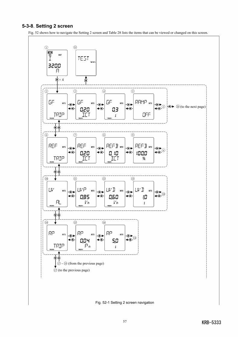
KRB-533357
5-3-8. Setting 2 screenFig. 52 shows how to navigate the Setting 2 screen and Table 28 lists the items that can be viewed or changed on this screen.
Fig. 52-1 Setting 2 screen navigation
1 31
× 4
2 2 4 5
2 26 (to the next page)
6 7 8 9
6
10 11 12 13
10
14 15 16
14
17 - 19 (from the previous page)
17 (to the previous page)
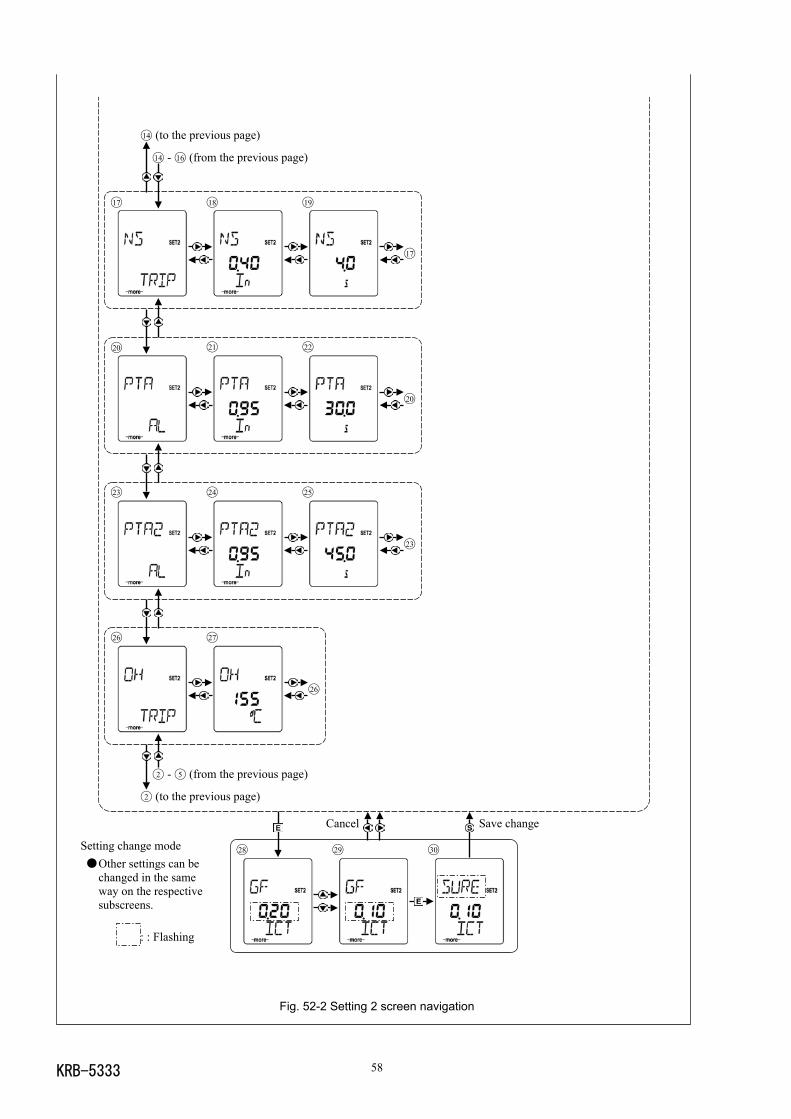
KRB-5333 58
Setting change mode Other settings can be
changed in the sameway on the respectivesubscreens.
: : Flashing
Fig. 52-2 Setting 2 screen navigation
14 (to the previous page)
14 - 16 (from the previous page)
17 18 19
17
20 21 22
20
23 24 25
23
26 27
26
2 - 5 (from the previous page)
2 (to the previous page)
Cancel Save change
28 29 30
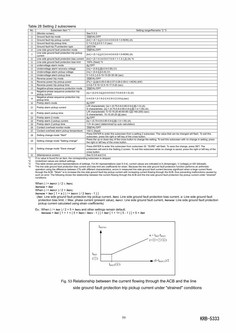
KRB-533359
Table 28 Setting 2 subscreensNo. Subscreen item *1 Setting range/Remarks *2 *31 (Monitor screen) See 5-3-3.2 Ground fault trip mode TRIP/AL/OFF3 Ground fault trip pickup current [ICT] × (0.1-0.2-0.3-0.4-0.6-0.8-1.0-NON) (A)4 Ground fault trip pickup time 0.1-0.2-0.3-0.5-1-2 (sec)5 Ground fault trip I2t protection type OFF/ON6 Line side ground fault protection mode TRIP/AL/OFF
7Line side ground fault protection trip pickupcurrent [ICT] × (0.1-0.2-0.3-0.4-0.6-0.8-1.0-NON) (A)
8 Line side ground fault protection bias current [ICT] × (0.1-0.3-0.5-0.7-0.9-1.1-1.3-1.5) (A) *49 Line side ground fault protection bias limit 100% (fixed) *410 undervoltage alarm mode AL/OFF11 Undervoltage alarm recovery voltage [Vn] × (0.8-0.85-0.9-0.95) (V)12 Undervoltage alarm pickup voltage [Vn] × (0.4-0.6-0.8) (V)13 Undervoltage alarm pickup time 0.1-0.5-1-2-5-10-15-20-30-36 (sec)14 Reverse power trip mode TRIP/AL/OFF15 Reverse power trip pickup power [Pn] × (0.04-0.05-0.06-0.07-0.08-0.09-0.1-NON) (kW)16 Reverse power trip pickup time 2.5-5-7.5-10-12.5-15-17.5-20 (sec)17 Negative-phase sequence protection mode TRIP/AL/OFF
18Negative-phase sequence protection trippickup current [In] × (0.2-0.3-0.4-0.5-0.6-0.7-0.8-0.9-1.0) (A)
19Negative-phase sequence protection trippickup time 0.4-0.8-1.2-1.6-2-2.4-2.8-3.2-3.6-4 (sec)
20 Pretrip alarm mode AL/OFF
21 Pretrip alarm pickup current L/R characteristic: [In] × (0.75-0.8-0.85-0.9-0.95-1.0) (A)S characteristic: [In] × (0.75-0.8-0.85-0.9-0.95-1.0-1.05) (A)
22 Pretrip alarm pickup time L/R characteristic: 5-10-15-20-40-60-80-120-160-200) (sec)S characteristic: 10-15-20-25-30 (sec)
23 Pretrip alarm 2 mode AL/OFF24 Pretrip alarm 2 pickup current [In] × (0.75-0.8-0.85-0.9-0.95-1.0-1.05) (A)25 Pretrip alarm 2 pickup time 1.5× tP1 (sec) (determined by auto calculation)26 Contact overheat monitor mode TRIP/AL/OFF27 Contact overheat alarm pickup temperature 155°C (fixed)
28 Setting change mode "Start" Press ENTER to enter this subscreen from a setting 2 subscreen. The value that can be changed will flash. To exit thissubscreen, press the right or left key of the cross button.
29 Setting change mode "Setting change" Press the up or down key of the cross button to change the setting. To exit this subscreen with no change in setting, pressthe right or left key of the cross button.
30 Setting change mode "Save change"Press ENTER to enter this subscreen from subscreen 29. "SURE" will flash. To save the change, press SET. Thesubscreen will exit to the Setting 2 screen. To exit this subscreen while no change is saved, press the right or left key of thecross button.
31 (Maintenance screen) See 5-3-8 and 5-4.*1: If no value is found for an item, the corresponding subscreen is skipped.*2: Underlined values are default settings.*3: This table shows percent representations of settings. For AV representations (see 5-3-4), current values are indicated in A (Amperage), V (voltage),or kW (kilowatt).*4: The line side ground fault protection bias current and bias limit are coefficients for strain. Because the line side ground fault protection function performs an arithmetic
operation using the difference between CTs with different characteristics, errors in measured line side ground fault current become significant when a large current flowsthrough the ACB. "Strain" is to increase the line side ground fault trip pickup current with increasing current flowing through the ACB, thus preventing malfunctions caused bysuch an error. The following shows the relationship between the current flowing through the ACB and the line side ground fault protection trip pickup current under "strained"conditions:
When ( i + iREFCT ) / 2 ≤ IREF2;IREFNOW = IREFWhen ( i + iREFCT ) / 2 > IREF2;IREFNOW = IREF [ 1 + a ( i + iREFCT ) / 2 IREF2 - 1 ] (IREF: Line side ground fault protection trip pickup current, IREF2: Line side ground fault protection bias current, a: Line side ground fault
protection bias limit, i: Max. phase current (present value), iREFCT: Line side ground fault current, IREFNOW: Line side ground fault protectionpickup current calculated using strain coefficients)
Ex.: When ( i + iREF ) / 2 = 5 × IREF2 and other settings remain default;IREFNOW = IREF [ 1 + 1 × 5 × IREF2 / IREF2 - 1 ] = IREF [ 1 + 1× 5 - 1 ] = 5 × IREF
Fig. 53 Relationship between the current flowing through the ACB and the line
side ground fault protection trip pickup current under "strained" conditions
IREF2(8 )
IREF
(7 )
IREFNO
(I+IREFCT)/2
α × IREF/IREF2
(=9 ×7 /8 )
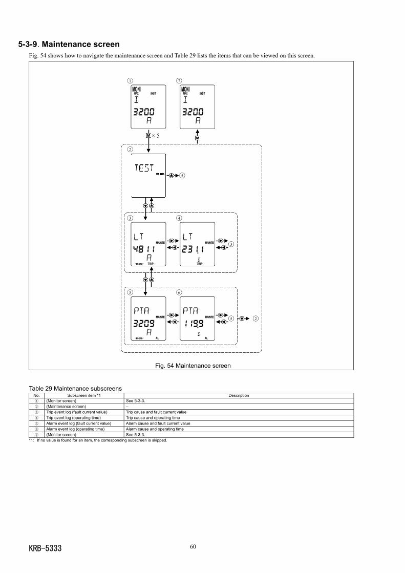
KRB-5333 60
5-3-9. Maintenance screenFig. 54 shows how to navigate the maintenance screen and Table 29 lists the items that can be viewed on this screen.
Fig. 54 Maintenance screen
Table 29 Maintenance subscreensNo. Subscreen item *1 Description1 (Monitor screen) See 5-3-3.2 (Maintenance screen) –3 Trip event log (fault current value) Trip cause and fault current value4 Trip event log (operating time) Trip cause and operating time5 Alarm event log (fault current value) Alarm cause and fault current value6 Alarm event log (operating time) Alarm cause and operating time7 (Monitor screen) See 5-3-3.
*1: If no value is found for an item, the corresponding subscreen is skipped.
1 7
× 5
2
5
3 4
3
5 6
5 2
KRB-533361
5-4. OCR Function Check CAUTION
OCR function check and setting changes must be performed by competent persons. After completion of OCR tests, be sure to return the settings to the original values. Failure to do so may cause a fire orburnout.
Use the following procedure to perform OCR function check.
1) Open the ACB and draw out the breaker body to the TEST position.
2) Change settings according to the test as shown in Table 30.
Table 30 OCR setting changesTest *1 Output signal value Setting to be changed
L characteristic: [IR] × 6 NonR characteristic: [IR] × 3 NonLong time delay tripS characteristic: [IR] × 1.2 Non
Short time delay trip [Isd] × 1.2 [Ii] >[Isd] × 1.5, Short time delay trip I2t protection: OFFInstantaneous trip Mode: INSTMCR [Ii] × 1.2 Mode: MCRGround fault trip [Ig] × 1.5 Ground fault trip I2t protection: OFF
*1: Setting an item to NON and OFF disables the test for the item.
3) To check the ACB along with the OCR, close the ACB before applying a test signal. When checking the MCR function, close the
ACB within 0.3 sec. after applying a test signal.
4) Follow the procedure described in Fig. 55 and Table 31 to check the OCR for normal operation. (In NTR mode, the ACB does not
operate, a trip/alarm event is not saved in the log and operation indication contact output is not provided).
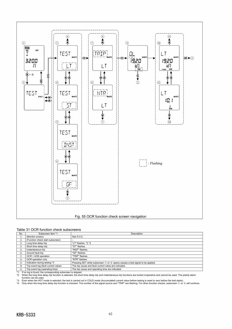
KRB-5333 62
: Flashing
Fig. 55 OCR function check screen navigation
Table 31 OCR function check subscreensNo. Subscreen item *1 Description1 (Monitor screen) See 5-3-3.2 (Function check start subscreen) –3 Long time delay trip "LT" flashes. *2 *34 Short time delay trip "ST" flashes.5 Instantaneous trip "INST" flashes.6 Ground fault trip "GF" flashes.7 OCR + ACB operation "TRIP" flashes.8 OCR operation only "NTR" flashes.9 Indication during testing *4 Pressing SET while subscreen 7 or 8 opens causes a test signal to be applied.10 Trip event log (fault current value) The trip cause and fault current value are indicated.11 Trip event log (operating time) The trip cause and operating time are indicated.
*1: If no log is found, the corresponding subscreen is skipped.*2: When the long time delay trip function is selected, the short time delay trip and instantaneous trip functions are locked inoperative and cannot be used. The pretrip alarm
function can be used.*3: Even when the HOT mode is selected, the test is carried out in COLD mode (Accumulated current value before testing is reset to zero before the test starts).*4: Only when the long time delay trip function is checked. The number of the signal source and "TRIP" are flashing. For other function checks, subscreen 7 or 8 will continue.
6 8 11
1 3 7 9 10
2
× 6
2 4 8 2 11
5 7 10
6
3
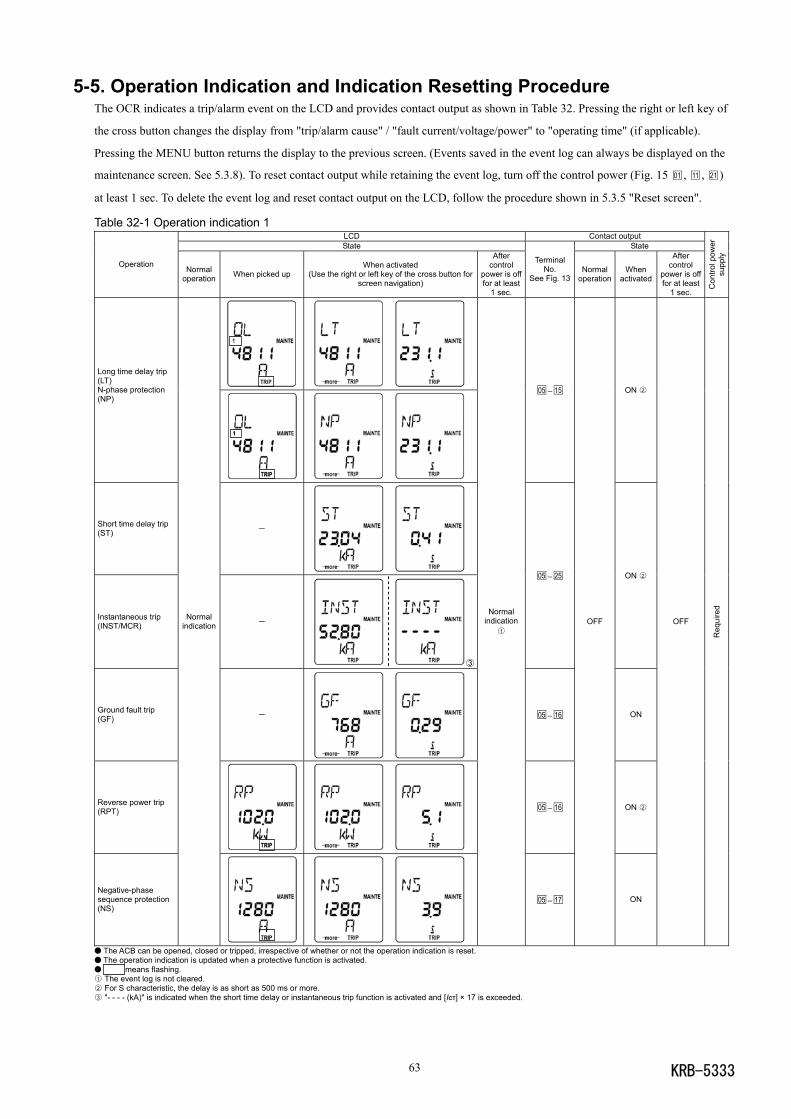
KRB-533363
5-5. Operation Indication and Indication Resetting ProcedureThe OCR indicates a trip/alarm event on the LCD and provides contact output as shown in Table 32. Pressing the right or left key of
the cross button changes the display from "trip/alarm cause" / "fault current/voltage/power" to "operating time" (if applicable).
Pressing the MENU button returns the display to the previous screen. (Events saved in the event log can always be displayed on the
maintenance screen. See 5.3.8). To reset contact output while retaining the event log, turn off the control power (Fig. 15 01 , 11 , 21 )
at least 1 sec. To delete the event log and reset contact output on the LCD, follow the procedure shown in 5.3.5 "Reset screen".
Table 32-1 Operation indication 1LCD Contact outputState State
Operation Normaloperation When picked up
When activated(Use the right or left key of the cross button for
screen navigation)
Aftercontrol
power is offfor at least
1 sec.
TerminalNo.
See Fig. 13Normal
operationWhen
activated
Aftercontrol
power is offfor at least
1 sec.
Con
trol p
ower
supp
ly
Long time delay trip(LT)N-phase protection(NP)
05 –15 ON 2
Short time delay trip(ST) -
Instantaneous trip(INST/MCR) -
③
05 –25 ON 2
Ground fault trip(GF) -
05 –16 ON
Reverse power trip(RPT)
05 –16 ON 2
Negative-phasesequence protection(NS)
Normalindication
Normalindication
1
05 –17
OFF
ON
OFF
Req
uire
d
The ACB can be opened, closed or tripped, irrespective of whether or not the operation indication is reset. The operation indication is updated when a protective function is activated. means flashing.1 The event log is not cleared.2 For S characteristic, the delay is as short as 500 ms or more.3 "- - - - (kA)" is indicated when the short time delay or instantaneous trip function is activated and [ICT] × 17 is exceeded.
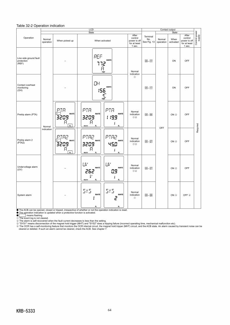
KRB-5333 64
Table 32-2 Operation indicationLCD Contact outputState State
Operation Normaloperation When picked up When activated
Aftercontrol
power is offfor at least
1 sec.
TerminalNo.
See Fig. 13Normal
operationWhen
activated
Aftercontrol
power is offfor at least
1 sec.
Con
trol p
ower
supp
ly
Line side ground faultprotection(REF)
– 05 –17 ON OFF
Contact overheatmonitoring(OH)
–
Normalindication
1
05 –17 ON OFF
Pretrip alarm (PTA)
Normalindication
1 205 –06 ON 2 OFF
Pretrip alarm 2(PTA2)
Normalindication
1 205 –27 ON 2 OFF
Undervoltage alarm(UV) –
Normalindication
1 205 –27 ON 2 OFF
System alarm
Normalindication
–
Normalindication
105 –26
OFF
ON 3 OFF 4R
equi
red
The ACB can be opened, closed or tripped, irrespective of whether or not the operation indication is reset. The operation indication is updated when a protective function is activated. means flashing1 The event log is not cleared.2 The alarm is self-recovered when the fault current decreases to less than the setting.3 "SYS1" means disconnection of the magnet hold trigger (MHT) and "SYS2" does a tripping failure (incorrect operating time, mechanical malfunction etc).4 The OCR has a self-monitoring feature that monitors the OCR internal circuit, the magnet hold tripper (MHT) circuit, and the ACB state. An alarm caused by transient noise can be
cleared or deleted. If such an alarm cannot be cleared, check the ACB. See chapter 7.
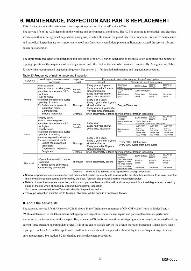
KRB-533365
6. MAINTENANCE, INSPECTION AND PARTS REPLACEMENTThis chapter describes the maintenance and inspection procedure for the AR series ACBs.
The service life of the ACB depends on the working and environmental conditions. The ACB is exposed to mechanical and electrical
stresses and thus suffers gradual degradation during use, which will increase the possibility of malfunctions. Preventive maintenance
and periodical inspection are very important to avoid any functional degradation, prevent malfunctions, extend the service life, and
ensure safe operation.
The appropriate frequency of maintenance and inspection of the ACB varies depending on the installation conditions, the number of
tripping operations, the magnitude of breaking current, and other factors that are to be considered empirically. As a guideline, Table
33 shows the recommended inspection frequency. See section 6-1 for detailed maintenance and inspection procedures.
Table 33 Frequency of maintenance and inspectionFrequency in interval or number of open/close cyclesCategory Working and environmental
conditionsInspection
level Interval Number of open/close cyclesOpen/closecondition 800AF or less 1250AF -
2500AF3200AF ormore
Nearly no currentlevel Every 1000 cyclesNormal/
Detailed
• Every year or 2 years• Every year after 3 years
since installation• Every half year after 6
years since installationRated currentlevel
Every 1000cycles
Every 500cycles
Every 100cycles
Thorough
• Every 5 or 6 years• Every 4 years after 6 years
since installation• Every year or 2 years after
10 years since installation
Every 4000 cycles
Normal
• Not so dusty,• Not so much corrosive gases,• Ambient temperature: 35°C
or lower• Not so humid,• Number of open/close cycles
per day: 2 or lessEx.Switchboards in electric
installation rooms,Control rooms,Building installation Overhaul When abnormality is found during normal or through inspection
Open/closecondition 800AF or less 1250AF -
2500AF3200AF ormore
Nearly no currentlevel
• Every 1000 cycles• Every 500 cycles after 1000 cyclesNormal/
Detailed
• Every year• Every half year after 2
years since installation Rated currentlevel
• Every 1000cycles
• Every 500cycles after1000 cycles
• Every 500cycles
• Every 250cycles after500 cycles
• Every 100cycles
• Every 50cycles after100 cycles
Thorough
• Every 2 or 3 years• Every 2 years after 6 years
since installation• Every year after 10 years
since installation
• Every 2500 - 3000 cycles• Every 2000 cycles after 3000 cycles
Harsh
• Highly dusty,• Much corrosive gases,• Ambient temperature: 45°C
or higher,• Highly humid,• Number of open/close cycles
per day: 4 or more,• Always exposed to vibrationsEx. Iron or chemical plants
Engine rooms (withoutventilation),Cogeneration installation,Ferryboats Overhaul When abnormality is found during normal or through inspection
Open/closecondition 800AF or less 1250AF -
2500AF3200AF ormore
Overcurrent level(approx. 6 timesthe rated current)
Every 25cycles
Every 25cycles
Every 25cyclesThorough When abnormality occurs
Level exceedingovercurrent level Every time Every time Every time
Abnormal
• Open/close operation due tooverload,
• Tripping due to shortcircuit,• Accidentally submerged
Overhaul When ACB is deemed to be repairable at through inspection Normal inspection includes inspection and actions that can be done only with removing the arc chamber, contacts, front cover and thelike. Normal inspection can be performed by the user. Terasaki also provides normal inspection service.
Detailed inspection includes inspection, actions, and parts replacement that will be done to prevent functional degradation caused byaging or the like when abnormality is found during normal inspection.You are recommended to use Terasaki’s detailed inspection service.
Thorough inspection must be left to Terasaki. Overhaul will be done in a Terasaki’s factory.
About the service lifeThe expected service life of AR series ACBs is shown in the "Endurance in number of ON-OFF cycles" rows in Tables 3 and 4.
"With maintenance" in the tables means that appropriate inspection, maintenance, repair, and parts replacement are performed
according to the instructions in this chapter. But, when an ACB performs three times of tripping operation nearly at the rated breaking
current (three standard operating duty cycles), it is at the end of its safe service life even if thorough inspection is done every time it
trips open. Such an ACB will be apt to suffer malfunctions and should be replaced without delay to avoid frequent inspection and
parts replacement. See section 6-2 for detailed parts replacement procedures.
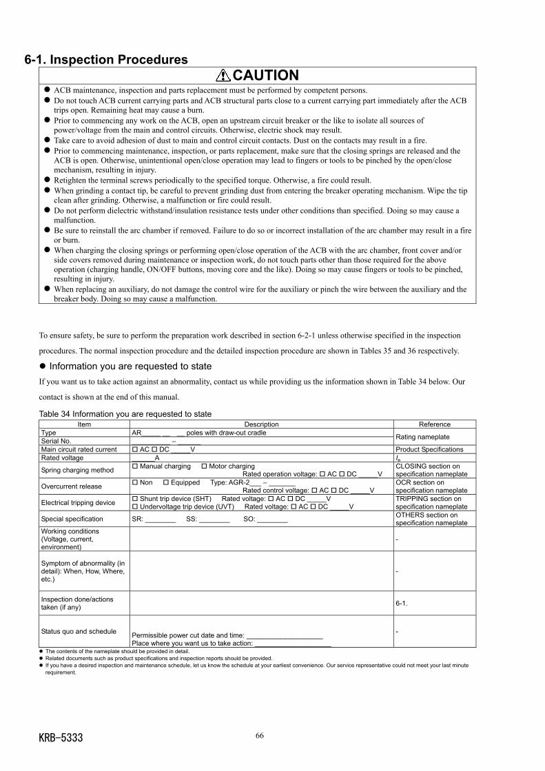
KRB-5333 66
6-1. Inspection Procedures CAUTION
ACB maintenance, inspection and parts replacement must be performed by competent persons. Do not touch ACB current carrying parts and ACB structural parts close to a current carrying part immediately after the ACBtrips open. Remaining heat may cause a burn.
Prior to commencing any work on the ACB, open an upstream circuit breaker or the like to isolate all sources ofpower/voltage from the main and control circuits. Otherwise, electric shock may result.
Take care to avoid adhesion of dust to main and control circuit contacts. Dust on the contacts may result in a fire. Prior to commencing maintenance, inspection, or parts replacement, make sure that the closing springs are released and theACB is open. Otherwise, unintentional open/close operation may lead to fingers or tools to be pinched by the open/closemechanism, resulting in injury.
Retighten the terminal screws periodically to the specified torque. Otherwise, a fire could result. When grinding a contact tip, be careful to prevent grinding dust from entering the breaker operating mechanism. Wipe the tipclean after grinding. Otherwise, a malfunction or fire could result.
Do not perform dielectric withstand/insulation resistance tests under other conditions than specified. Doing so may cause amalfunction.
Be sure to reinstall the arc chamber if removed. Failure to do so or incorrect installation of the arc chamber may result in a fireor burn.
When charging the closing springs or performing open/close operation of the ACB with the arc chamber, front cover and/orside covers removed during maintenance or inspection work, do not touch parts other than those required for the aboveoperation (charging handle, ON/OFF buttons, moving core and the like). Doing so may cause fingers or tools to be pinched,resulting in injury.
When replacing an auxiliary, do not damage the control wire for the auxiliary or pinch the wire between the auxiliary and thebreaker body. Doing so may cause a malfunction.
To ensure safety, be sure to perform the preparation work described in section 6-2-1 unless otherwise specified in the inspection
procedures. The normal inspection procedure and the detailed inspection procedure are shown in Tables 35 and 36 respectively.
Information you are requested to stateIf you want us to take action against an abnormality, contact us while providing us the information shown in Table 34 below. Our
contact is shown at the end of this manual.
Table 34 Information you are requested to stateItem Description Reference
Type AR_____ __ __ poles with draw-out cradleSerial No. __________ – ______ Rating nameplate
Main circuit rated current AC DC _____V Product SpecificationsRated voltage ______A InSpring charging method Manual charging Motor charging
Rated operation voltage: AC DC _____VCLOSING section onspecification nameplate
Overcurrent release Non Equipped Type: AGR-2___ – _______Rated control voltage: AC DC _____V
OCR section onspecification nameplate
Electrical tripping device Shunt trip device (SHT) Rated voltage: AC DC _____V Undervoltage trip device (UVT) Rated voltage: AC DC _____V
TRIPPING section onspecification nameplate
Special specification SR: ________ SS: ________ SO: ________ OTHERS section onspecification nameplate
Working conditions(Voltage, current,environment)
-
Symptom of abnormality (indetail): When, How, Where,etc.)
-
Inspection done/actionstaken (if any) 6-1.
Status quo and schedule Permissible power cut date and time: ____________________Place where you want us to take action: ____________________
-
The contents of the nameplate should be provided in detail. Related documents such as product specifications and inspection reports should be provided. If you have a desired inspection and maintenance schedule, let us know the schedule at your earliest convenience. Our service representative could not meet your last minuterequirement.
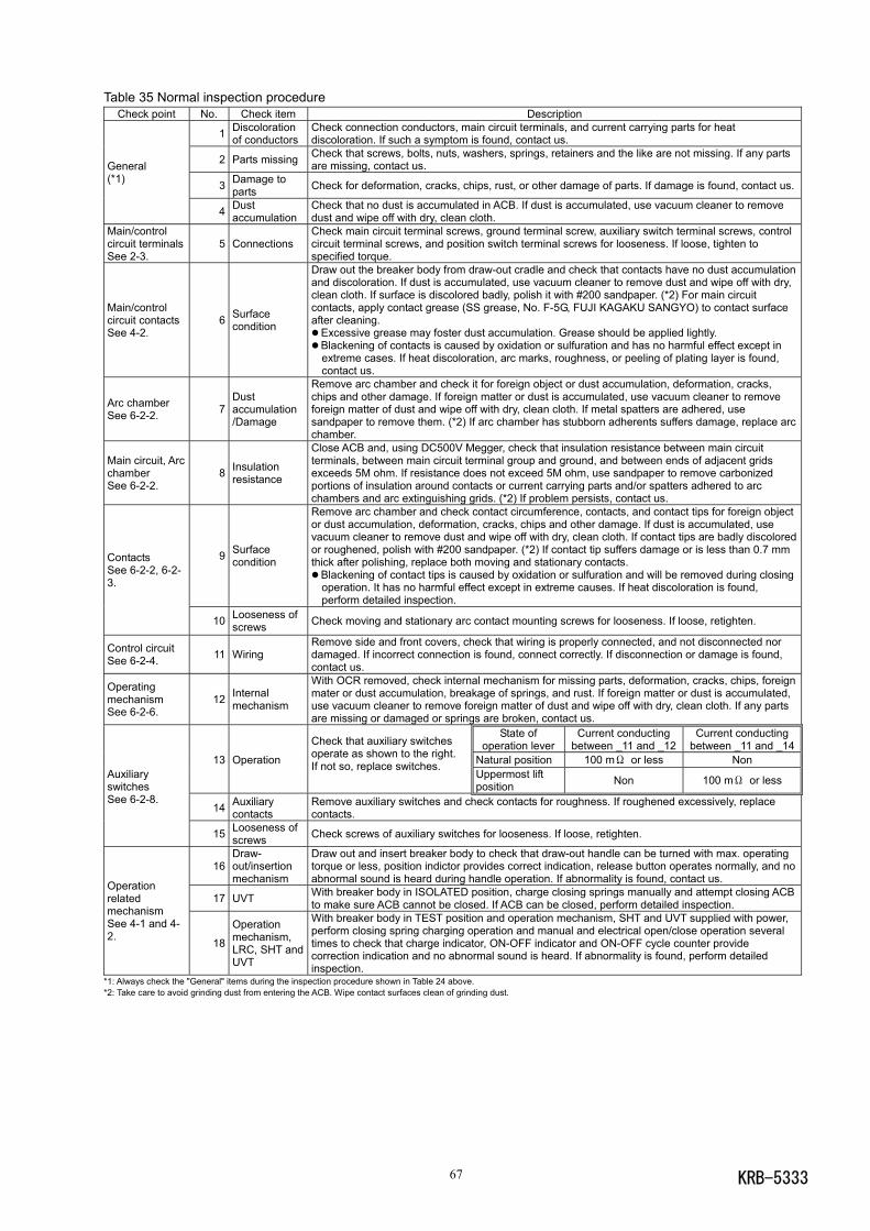
KRB-533367
Table 35 Normal inspection procedureCheck point No. Check item Description
1 Discolorationof conductors
Check connection conductors, main circuit terminals, and current carrying parts for heatdiscoloration. If such a symptom is found, contact us.
2 Parts missing Check that screws, bolts, nuts, washers, springs, retainers and the like are not missing. If any partsare missing, contact us.
3 Damage toparts Check for deformation, cracks, chips, rust, or other damage of parts. If damage is found, contact us.
General(*1)
4 Dustaccumulation
Check that no dust is accumulated in ACB. If dust is accumulated, use vacuum cleaner to removedust and wipe off with dry, clean cloth.
Main/controlcircuit terminalsSee 2-3.
5 ConnectionsCheck main circuit terminal screws, ground terminal screw, auxiliary switch terminal screws, controlcircuit terminal screws, and position switch terminal screws for looseness. If loose, tighten tospecified torque.
Main/controlcircuit contactsSee 4-2.
6 Surfacecondition
Draw out the breaker body from draw-out cradle and check that contacts have no dust accumulationand discoloration. If dust is accumulated, use vacuum cleaner to remove dust and wipe off with dry,clean cloth. If surface is discolored badly, polish it with #200 sandpaper. (*2) For main circuitcontacts, apply contact grease (SS grease, No. F-5G, FUJI KAGAKU SANGYO) to contact surfaceafter cleaning.
Excessive grease may foster dust accumulation. Grease should be applied lightly. Blackening of contacts is caused by oxidation or sulfuration and has no harmful effect except inextreme cases. If heat discoloration, arc marks, roughness, or peeling of plating layer is found,contact us.
Arc chamberSee 6-2-2. 7
Dustaccumulation/Damage
Remove arc chamber and check it for foreign object or dust accumulation, deformation, cracks,chips and other damage. If foreign matter or dust is accumulated, use vacuum cleaner to removeforeign matter of dust and wipe off with dry, clean cloth. If metal spatters are adhered, usesandpaper to remove them. (*2) If arc chamber has stubborn adherents suffers damage, replace arcchamber.
Main circuit, ArcchamberSee 6-2-2.
8 Insulationresistance
Close ACB and, using DC500V Megger, check that insulation resistance between main circuitterminals, between main circuit terminal group and ground, and between ends of adjacent gridsexceeds 5M ohm. If resistance does not exceed 5M ohm, use sandpaper to remove carbonizedportions of insulation around contacts or current carrying parts and/or spatters adhered to arcchambers and arc extinguishing grids. (*2) If problem persists, contact us.
9 Surfacecondition
Remove arc chamber and check contact circumference, contacts, and contact tips for foreign objector dust accumulation, deformation, cracks, chips and other damage. If dust is accumulated, usevacuum cleaner to remove dust and wipe off with dry, clean cloth. If contact tips are badly discoloredor roughened, polish with #200 sandpaper. (*2) If contact tip suffers damage or is less than 0.7 mmthick after polishing, replace both moving and stationary contacts.
Blackening of contact tips is caused by oxidation or sulfuration and will be removed during closingoperation. It has no harmful effect except in extreme causes. If heat discoloration is found,perform detailed inspection.
ContactsSee 6-2-2, 6-2-3.
10 Looseness ofscrews Check moving and stationary arc contact mounting screws for looseness. If loose, retighten.
Control circuitSee 6-2-4. 11 Wiring
Remove side and front covers, check that wiring is properly connected, and not disconnected nordamaged. If incorrect connection is found, connect correctly. If disconnection or damage is found,contact us.
OperatingmechanismSee 6-2-6.
12 Internalmechanism
With OCR removed, check internal mechanism for missing parts, deformation, cracks, chips, foreignmater or dust accumulation, breakage of springs, and rust. If foreign matter or dust is accumulated,use vacuum cleaner to remove foreign matter of dust and wipe off with dry, clean cloth. If any partsare missing or damaged or springs are broken, contact us.
State ofoperation lever
Current conductingbetween _11 and _12
Current conductingbetween _11 and _14
Natural position 100 mΩ or less Non13 Operation
Check that auxiliary switchesoperate as shown to the right.If not so, replace switches.
Uppermost liftposition Non 100 mΩ or less
14 Auxiliarycontacts
Remove auxiliary switches and check contacts for roughness. If roughened excessively, replacecontacts.
AuxiliaryswitchesSee 6-2-8.
15 Looseness ofscrews Check screws of auxiliary switches for looseness. If loose, retighten.
16Draw-out/insertionmechanism
Draw out and insert breaker body to check that draw-out handle can be turned with max. operatingtorque or less, position indictor provides correct indication, release button operates normally, and noabnormal sound is heard during handle operation. If abnormality is found, contact us.
17 UVT With breaker body in ISOLATED position, charge closing springs manually and attempt closing ACBto make sure ACB cannot be closed. If ACB can be closed, perform detailed inspection.
OperationrelatedmechanismSee 4-1 and 4-2. 18
Operationmechanism,LRC, SHT andUVT
With breaker body in TEST position and operation mechanism, SHT and UVT supplied with power,perform closing spring charging operation and manual and electrical open/close operation severaltimes to check that charge indicator, ON-OFF indicator and ON-OFF cycle counter providecorrection indication and no abnormal sound is heard. If abnormality is found, perform detailedinspection.
*1: Always check the "General" items during the inspection procedure shown in Table 24 above.*2: Take care to avoid grinding dust from entering the ACB. Wipe contact surfaces clean of grinding dust.
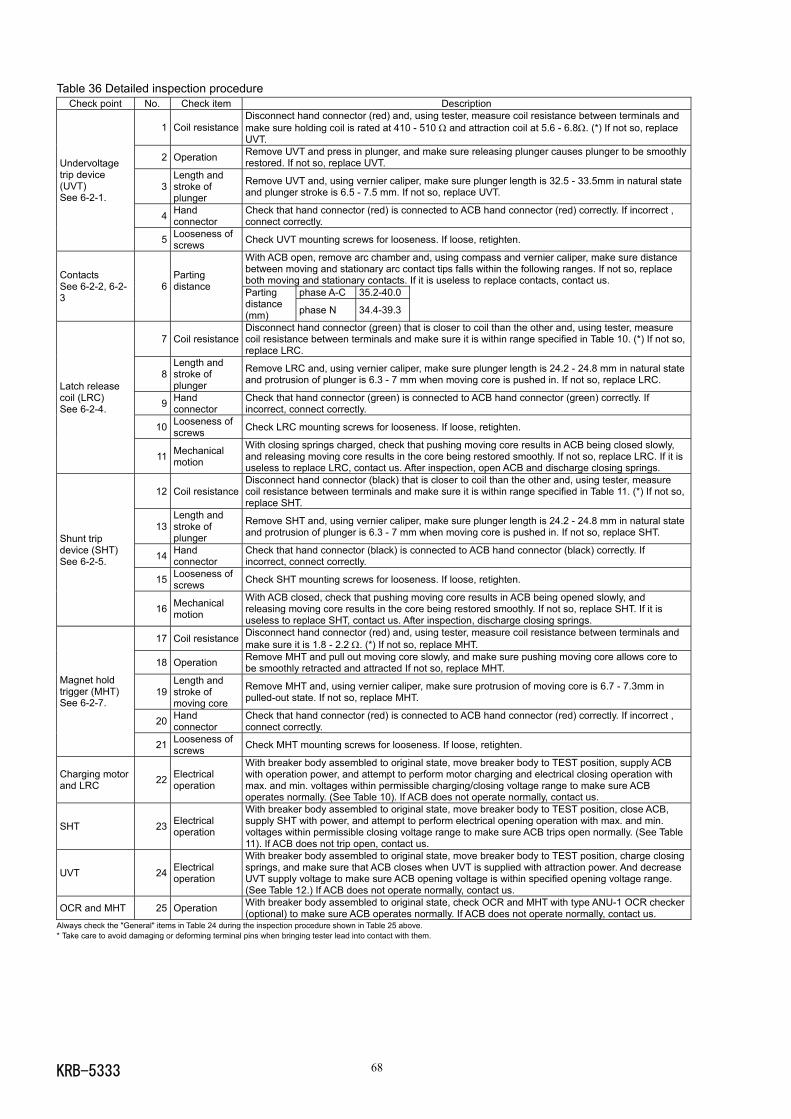
KRB-5333 68
Table 36 Detailed inspection procedureCheck point No. Check item Description
1 Coil resistanceDisconnect hand connector (red) and, using tester, measure coil resistance between terminals andmake sure holding coil is rated at 410 - 510 Ω and attraction coil at 5.6 - 6.8Ω. (*) If not so, replaceUVT.
2 Operation Remove UVT and press in plunger, and make sure releasing plunger causes plunger to be smoothlyrestored. If not so, replace UVT.
3Length andstroke ofplunger
Remove UVT and, using vernier caliper, make sure plunger length is 32.5 - 33.5mm in natural stateand plunger stroke is 6.5 - 7.5 mm. If not so, replace UVT.
4 Handconnector
Check that hand connector (red) is connected to ACB hand connector (red) correctly. If incorrect ,connect correctly.
Undervoltagetrip device(UVT)See 6-2-1.
5 Looseness ofscrews Check UVT mounting screws for looseness. If loose, retighten.
With ACB open, remove arc chamber and, using compass and vernier caliper, make sure distancebetween moving and stationary arc contact tips falls within the following ranges. If not so, replaceboth moving and stationary contacts. If it is useless to replace contacts, contact us.
phase A-C 35.2-40.0
ContactsSee 6-2-2, 6-2-3
6Partingdistance Parting
distance(mm) phase N 34.4-39.3
7 Coil resistanceDisconnect hand connector (green) that is closer to coil than the other and, using tester, measurecoil resistance between terminals and make sure it is within range specified in Table 10. (*) If not so,replace LRC.
8Length andstroke ofplunger
Remove LRC and, using vernier caliper, make sure plunger length is 24.2 - 24.8 mm in natural stateand protrusion of plunger is 6.3 - 7 mm when moving core is pushed in. If not so, replace LRC.
9 Handconnector
Check that hand connector (green) is connected to ACB hand connector (green) correctly. Ifincorrect, connect correctly.
10 Looseness ofscrews Check LRC mounting screws for looseness. If loose, retighten.
Latch releasecoil (LRC)See 6-2-4.
11 Mechanicalmotion
With closing springs charged, check that pushing moving core results in ACB being closed slowly,and releasing moving core results in the core being restored smoothly. If not so, replace LRC. If it isuseless to replace LRC, contact us. After inspection, open ACB and discharge closing springs.
12 Coil resistanceDisconnect hand connector (black) that is closer to coil than the other and, using tester, measurecoil resistance between terminals and make sure it is within range specified in Table 11. (*) If not so,replace SHT.
13Length andstroke ofplunger
Remove SHT and, using vernier caliper, make sure plunger length is 24.2 - 24.8 mm in natural stateand protrusion of plunger is 6.3 - 7 mm when moving core is pushed in. If not so, replace SHT.
14 Handconnector
Check that hand connector (black) is connected to ACB hand connector (black) correctly. Ifincorrect, connect correctly.
15 Looseness ofscrews Check SHT mounting screws for looseness. If loose, retighten.
Shunt tripdevice (SHT)See 6-2-5.
16 Mechanicalmotion
With ACB closed, check that pushing moving core results in ACB being opened slowly, andreleasing moving core results in the core being restored smoothly. If not so, replace SHT. If it isuseless to replace SHT, contact us. After inspection, discharge closing springs.
17 Coil resistance Disconnect hand connector (red) and, using tester, measure coil resistance between terminals andmake sure it is 1.8 - 2.2 Ω. (*) If not so, replace MHT.
18 Operation Remove MHT and pull out moving core slowly, and make sure pushing moving core allows core tobe smoothly retracted and attracted If not so, replace MHT.
19Length andstroke ofmoving core
Remove MHT and, using vernier caliper, make sure protrusion of moving core is 6.7 - 7.3mm inpulled-out state. If not so, replace MHT.
20 Handconnector
Check that hand connector (red) is connected to ACB hand connector (red) correctly. If incorrect ,connect correctly.
Magnet holdtrigger (MHT)See 6-2-7.
21 Looseness ofscrews Check MHT mounting screws for looseness. If loose, retighten.
Charging motorand LRC 22 Electrical
operation
With breaker body assembled to original state, move breaker body to TEST position, supply ACBwith operation power, and attempt to perform motor charging and electrical closing operation withmax. and min. voltages within permissible charging/closing voltage range to make sure ACBoperates normally. (See Table 10). If ACB does not operate normally, contact us.
SHT 23 Electricaloperation
With breaker body assembled to original state, move breaker body to TEST position, close ACB,supply SHT with power, and attempt to perform electrical opening operation with max. and min.voltages within permissible closing voltage range to make sure ACB trips open normally. (See Table11). If ACB does not trip open, contact us.
UVT 24 Electricaloperation
With breaker body assembled to original state, move breaker body to TEST position, charge closingsprings, and make sure that ACB closes when UVT is supplied with attraction power. And decreaseUVT supply voltage to make sure ACB opening voltage is within specified opening voltage range.(See Table 12.) If ACB does not operate normally, contact us.
OCR and MHT 25 Operation With breaker body assembled to original state, check OCR and MHT with type ANU-1 OCR checker(optional) to make sure ACB operates normally. If ACB does not operate normally, contact us.
Always check the "General" items in Table 24 during the inspection procedure shown in Table 25 above.* Take care to avoid damaging or deforming terminal pins when bringing tester lead into contact with them.
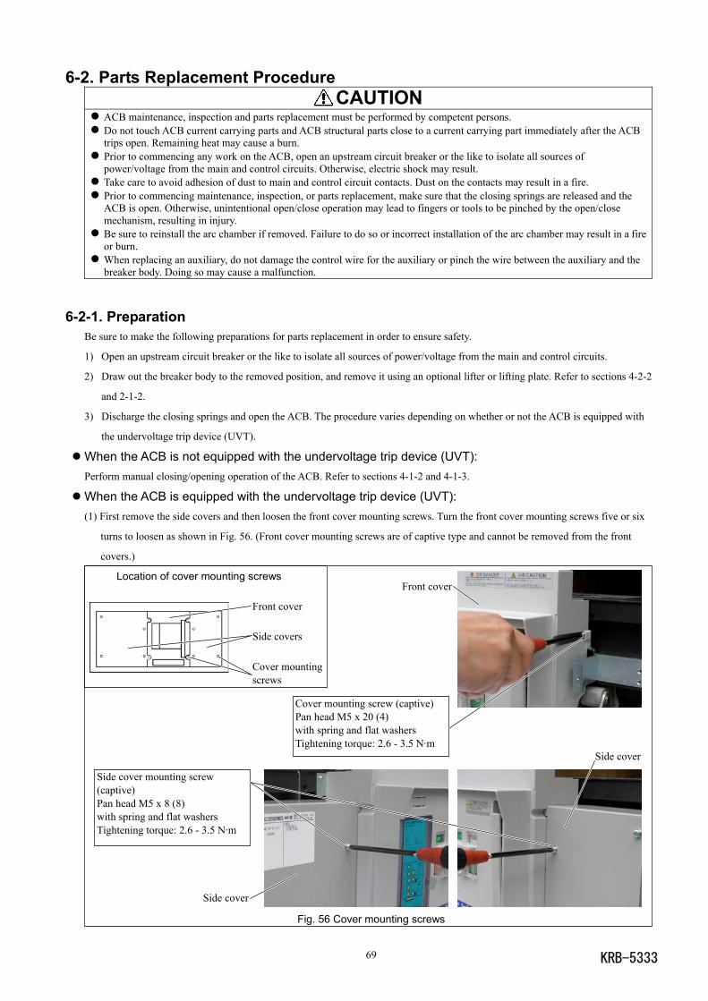
KRB-533369
Side cover mounting screw(captive)Pan head M5 x 8 (8)with spring and flat washersTightening torque: 2.6 - 3.5 N·m
Front cover
Front cover
Side covers
Cover mountingscrews
Cover mounting screw (captive)Pan head M5 x 20 (4)with spring and flat washersTightening torque: 2.6 - 3.5 N·m
Side cover
Side cover
6-2. Parts Replacement Procedure CAUTION
ACB maintenance, inspection and parts replacement must be performed by competent persons. Do not touch ACB current carrying parts and ACB structural parts close to a current carrying part immediately after the ACBtrips open. Remaining heat may cause a burn.
Prior to commencing any work on the ACB, open an upstream circuit breaker or the like to isolate all sources ofpower/voltage from the main and control circuits. Otherwise, electric shock may result.
Take care to avoid adhesion of dust to main and control circuit contacts. Dust on the contacts may result in a fire. Prior to commencing maintenance, inspection, or parts replacement, make sure that the closing springs are released and theACB is open. Otherwise, unintentional open/close operation may lead to fingers or tools to be pinched by the open/closemechanism, resulting in injury.
Be sure to reinstall the arc chamber if removed. Failure to do so or incorrect installation of the arc chamber may result in a fireor burn.
When replacing an auxiliary, do not damage the control wire for the auxiliary or pinch the wire between the auxiliary and thebreaker body. Doing so may cause a malfunction.
6-2-1. PreparationBe sure to make the following preparations for parts replacement in order to ensure safety.
1) Open an upstream circuit breaker or the like to isolate all sources of power/voltage from the main and control circuits.
2) Draw out the breaker body to the removed position, and remove it using an optional lifter or lifting plate. Refer to sections 4-2-2
and 2-1-2.
3) Discharge the closing springs and open the ACB. The procedure varies depending on whether or not the ACB is equipped with
the undervoltage trip device (UVT).
When the ACB is not equipped with the undervoltage trip device (UVT):Perform manual closing/opening operation of the ACB. Refer to sections 4-1-2 and 4-1-3.
When the ACB is equipped with the undervoltage trip device (UVT):(1) First remove the side covers and then loosen the front cover mounting screws. Turn the front cover mounting screws five or six
turns to loosen as shown in Fig. 56. (Front cover mounting screws are of captive type and cannot be removed from the front
covers.)
Location of cover mounting screws
Fig. 56 Cover mounting screws
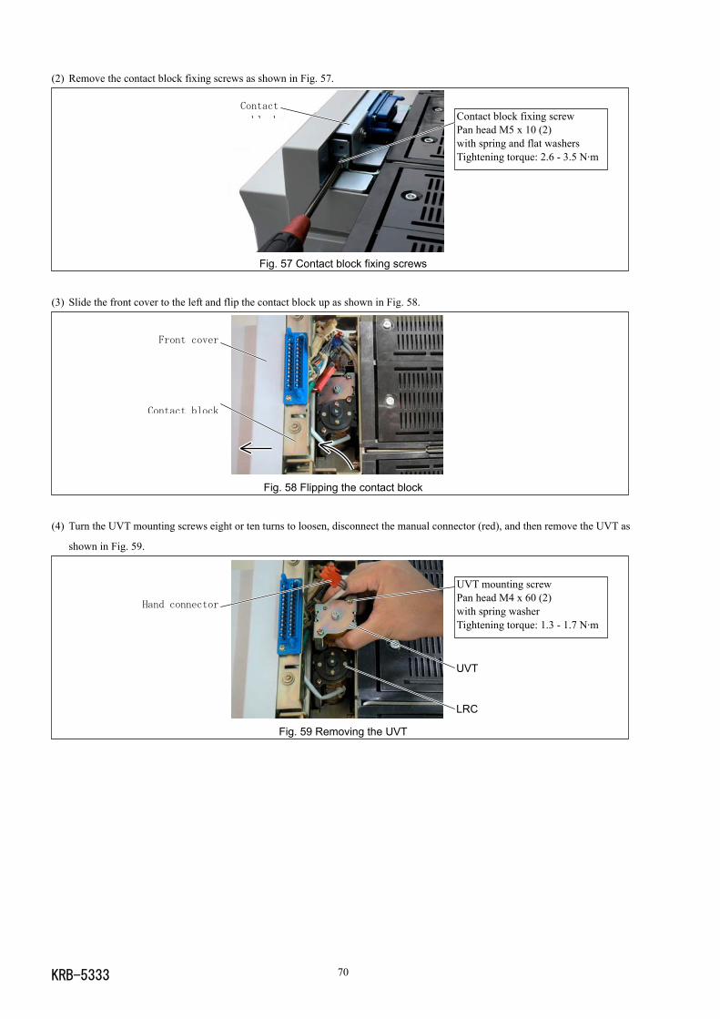
KRB-5333 70
(2) Remove the contact block fixing screws as shown in Fig. 57.
Fig. 57 Contact block fixing screws
(3) Slide the front cover to the left and flip the contact block up as shown in Fig. 58.
Fig. 58 Flipping the contact block
(4) Turn the UVT mounting screws eight or ten turns to loosen, disconnect the manual connector (red), and then remove the UVT as
shown in Fig. 59.
Fig. 59 Removing the UVT
UVT mounting screwPan head M4 x 60 (2)with spring washerTightening torque: 1.3 - 1.7 N·m
Hand connector
UVT
LRC
Front cover
Contact block
Contact block fixing screwPan head M5 x 10 (2)with spring and flat washersTightening torque: 2.6 - 3.5 N·m
Contact
block
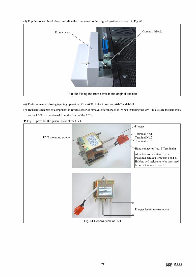
KRB-533371
Contact blockFront cover
(5) Flip the contact block down and slide the front cover to the original position as shown in Fig. 60.
Fig. 60 Sliding the front cover to the original position
(6) Perform manual closing/opening operation of the ACB. Refer to sections 4-1-2 and 4-1-3.
(7) Reinstall each part or component in reverse order of removal after inspection. When installing the UVT, make sure the nameplate
on the UVT can be viewed from the front of the ACB.
Fig. 61 provides the general view of the UVT.
Fig. 61 General view of UVT
Plunger
Terminal No.1Terminal No.2Terminal No.3
Hand connector (red, 3 Terminals)
Attraction coil resistance to bemeasured between terminals 1 and 2.Holding coil resistance to be measuredbetween terminals 1 and 3.
Plunger length measurement
UVT mounting screw
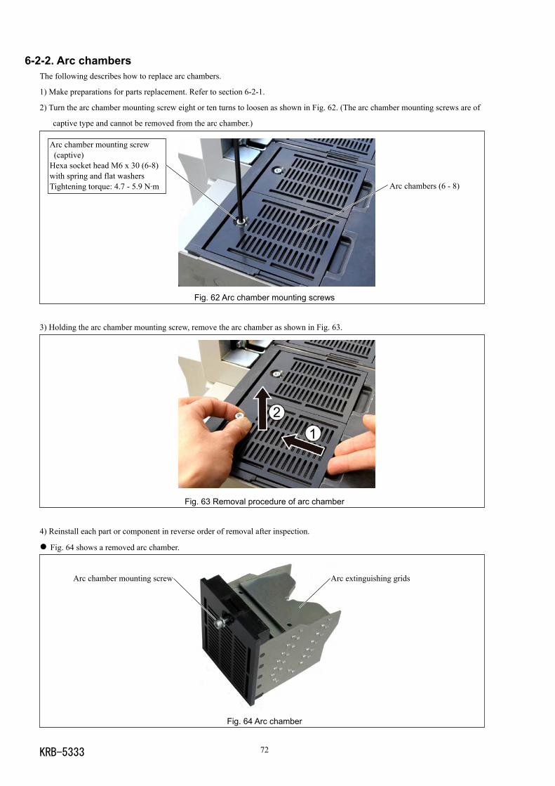
KRB-5333 72
Arc chambers (6 - 8)
Arc chamber mounting screw (captive)Hexa socket head M6 x 30 (6-8)with spring and flat washersTightening torque: 4.7 - 5.9 N·m
6-2-2. Arc chambersThe following describes how to replace arc chambers.
1) Make preparations for parts replacement. Refer to section 6-2-1.
2) Turn the arc chamber mounting screw eight or ten turns to loosen as shown in Fig. 62. (The arc chamber mounting screws are of
captive type and cannot be removed from the arc chamber.)
Fig. 62 Arc chamber mounting screws
3) Holding the arc chamber mounting screw, remove the arc chamber as shown in Fig. 63.
Fig. 63 Removal procedure of arc chamber
4) Reinstall each part or component in reverse order of removal after inspection.
Fig. 64 shows a removed arc chamber.
Fig. 64 Arc chamber
Fig. 64 Arc chamber
Arc extinguishing gridsArc chamber mounting screw
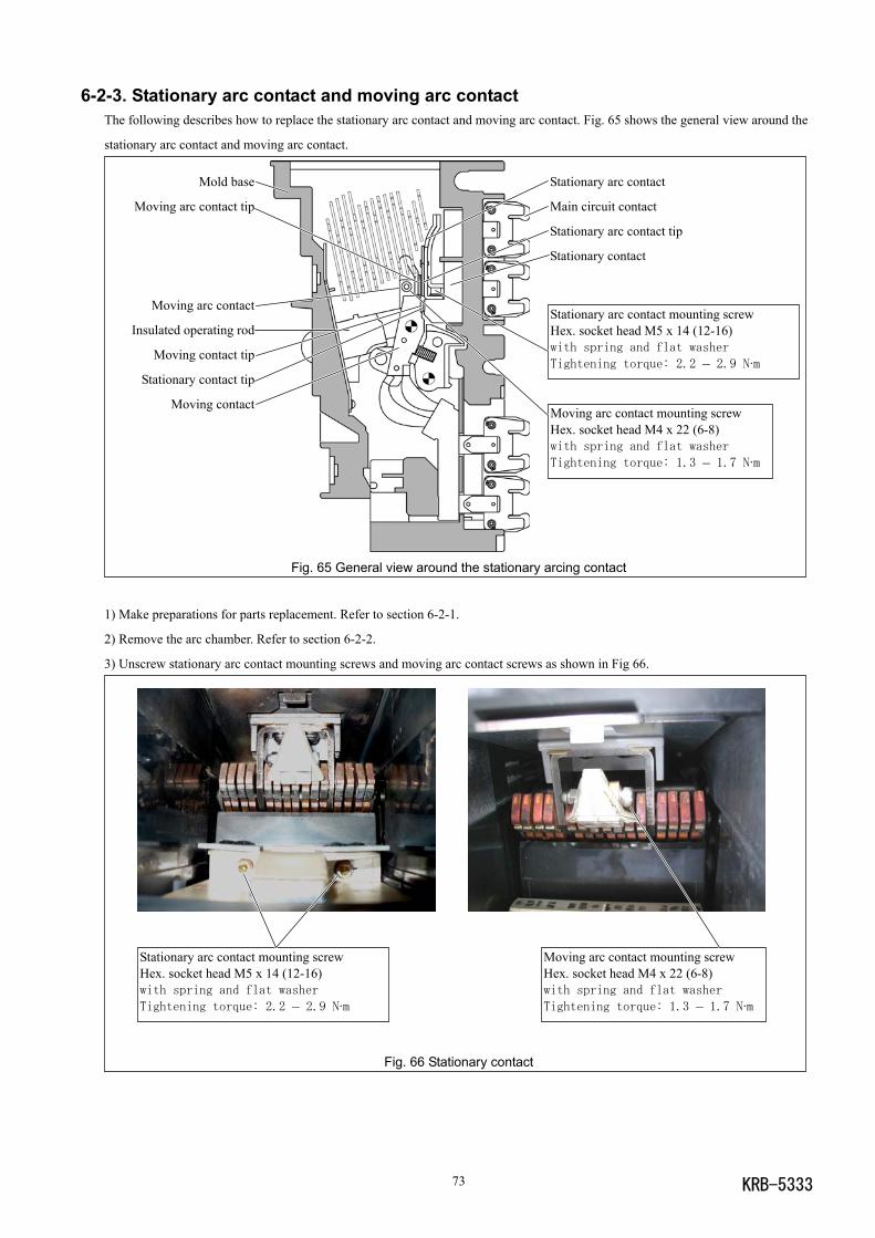
KRB-533373
6-2-3. Stationary arc contact and moving arc contactThe following describes how to replace the stationary arc contact and moving arc contact. Fig. 65 shows the general view around the
stationary arc contact and moving arc contact.
Fig. 65 General view around the stationary arcing contact
1) Make preparations for parts replacement. Refer to section 6-2-1.
2) Remove the arc chamber. Refer to section 6-2-2.
3) Unscrew stationary arc contact mounting screws and moving arc contact screws as shown in Fig 66.
Fig. 66 Stationary contact
Stationary arc contact mounting screwHex. socket head M5 x 14 (12-16)with spring and flat washer
Tightening torque: 2.2 – 2.9 N·m
Moving arc contact mounting screwHex. socket head M4 x 22 (6-8)with spring and flat washer
Tightening torque: 1.3 – 1.7 N·m
Mold base
Moving arc contact tip
Moving arc contact
Insulated operating rod
Moving contact tip
Stationary contact tip
Moving contactMoving arc contact mounting screwHex. socket head M4 x 22 (6-8)with spring and flat washer
Tightening torque: 1.3 – 1.7 N·m
Stationary arc contact
Main circuit contact
Stationary arc contact tip
Stationary contact
Stationary arc contact mounting screwHex. socket head M5 x 14 (12-16)with spring and flat washer
Tightening torque: 2.2 – 2.9 N·m
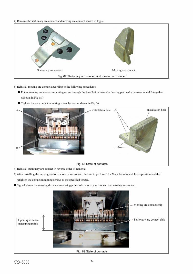
KRB-5333 74
4) Remove the stationary arc contact and moving arc contact shown in Fig 67.
Stationary arc contact Moving arc contact
Fig. 67 Stationary arc contact and moving arc contact
5) Reinstall moving arc contact according to the following procedures.
Put an moving arc contact mounting screw through the installation hole after having put masks between A and B together .
(Shown in Fig 68.)
Tighten the arc contact mounting screw by torque shown in Fig 66.
Fig. 68 State of contacts6) Reinstall stationary arc contact in reverse order of removal.
7) After installing the moving and/or stationary arc contact, be sure to perform 10 - 20 cycles of open/close operation and then
retighten the contact mounting screws to the specified torque.
Fig. 69 shows the opening distance measuring points of stationary arc contact and moving arc contact.
Fig. 69 State of contacts
A
B
installation hole installation hole
B
A
Opening distancemeasuring points
Moving arc contact chip
Stationary arc contact chip
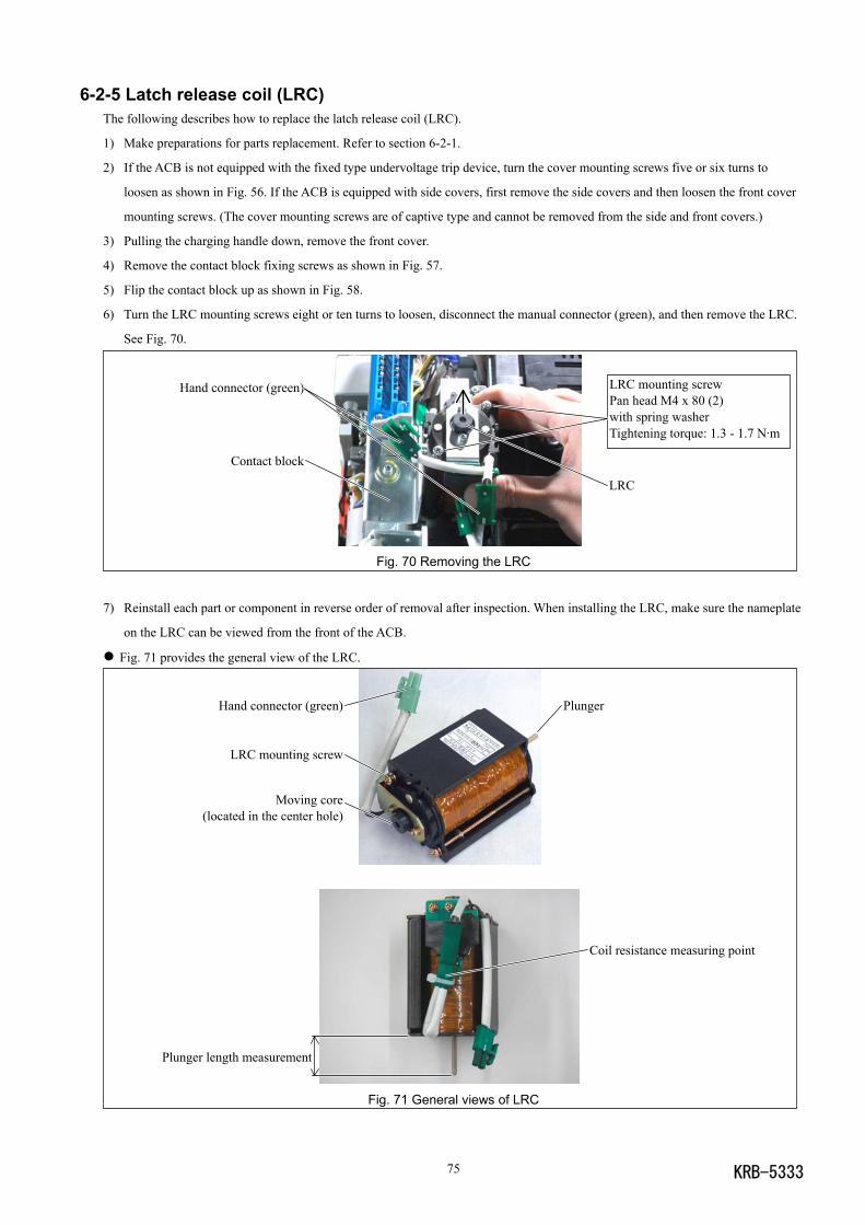
KRB-533375
6-2-5 Latch release coil (LRC)The following describes how to replace the latch release coil (LRC).
1) Make preparations for parts replacement. Refer to section 6-2-1.
2) If the ACB is not equipped with the fixed type undervoltage trip device, turn the cover mounting screws five or six turns to
loosen as shown in Fig. 56. If the ACB is equipped with side covers, first remove the side covers and then loosen the front cover
mounting screws. (The cover mounting screws are of captive type and cannot be removed from the side and front covers.)
3) Pulling the charging handle down, remove the front cover.
4) Remove the contact block fixing screws as shown in Fig. 57.
5) Flip the contact block up as shown in Fig. 58.
6) Turn the LRC mounting screws eight or ten turns to loosen, disconnect the manual connector (green), and then remove the LRC.
See Fig. 70.
Fig. 70 Removing the LRC
7) Reinstall each part or component in reverse order of removal after inspection. When installing the LRC, make sure the nameplate
on the LRC can be viewed from the front of the ACB.
Fig. 71 provides the general view of the LRC.
Fig. 71 General views of LRC
LRC
Hand connector (green)
Contact block
LRC mounting screwPan head M4 x 80 (2)with spring washerTightening torque: 1.3 - 1.7 N·m
Plunger
Coil resistance measuring point
Hand connector (green)
LRC mounting screw
Moving core(located in the center hole)
Plunger length measurement
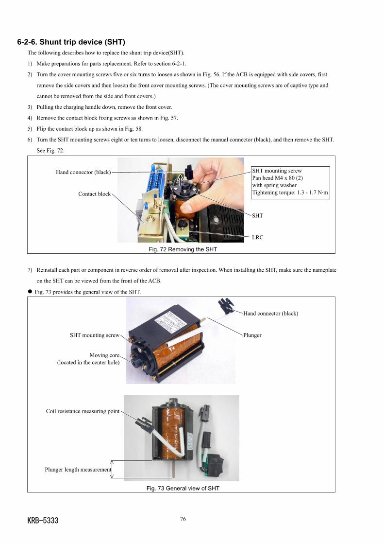
KRB-5333 76
6-2-6. Shunt trip device (SHT)The following describes how to replace the shunt trip device(SHT).
1) Make preparations for parts replacement. Refer to section 6-2-1.
2) Turn the cover mounting screws five or six turns to loosen as shown in Fig. 56. If the ACB is equipped with side covers, first
remove the side covers and then loosen the front cover mounting screws. (The cover mounting screws are of captive type and
cannot be removed from the side and front covers.)
3) Pulling the charging handle down, remove the front cover.
4) Remove the contact block fixing screws as shown in Fig. 57.
5) Flip the contact block up as shown in Fig. 58.
6) Turn the SHT mounting screws eight or ten turns to loosen, disconnect the manual connector (black), and then remove the SHT.
See Fig. 72.
Fig. 72 Removing the SHT
7) Reinstall each part or component in reverse order of removal after inspection. When installing the SHT, make sure the nameplate
on the SHT can be viewed from the front of the ACB.
Fig. 73 provides the general view of the SHT.
Fig. 73 General view of SHT
Hand connector (black)
Contact block
SHT mounting screwPan head M4 x 80 (2)with spring washerTightening torque: 1.3 - 1.7 N·m
SHT
LRC
Hand connector (black)
PlungerSHT mounting screw
Moving core(located in the center hole)
Coil resistance measuring point
Plunger length measurement
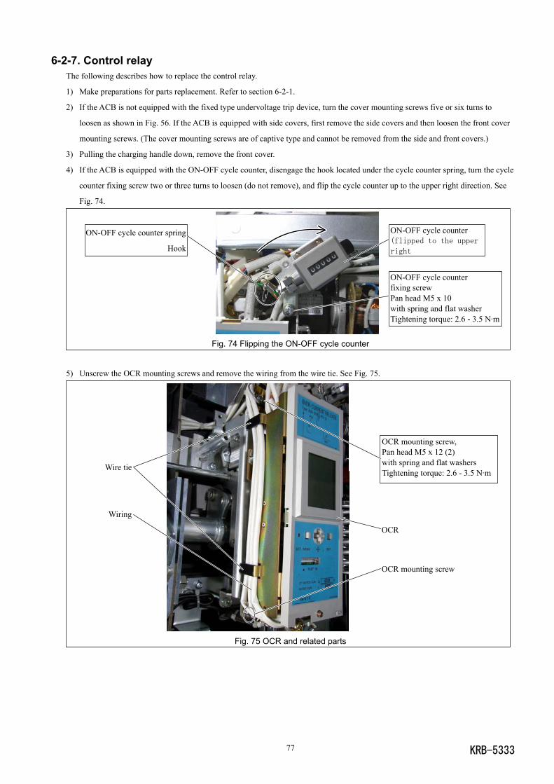
KRB-533377
6-2-7. Control relayThe following describes how to replace the control relay.
1) Make preparations for parts replacement. Refer to section 6-2-1.
2) If the ACB is not equipped with the fixed type undervoltage trip device, turn the cover mounting screws five or six turns to
loosen as shown in Fig. 56. If the ACB is equipped with side covers, first remove the side covers and then loosen the front cover
mounting screws. (The cover mounting screws are of captive type and cannot be removed from the side and front covers.)
3) Pulling the charging handle down, remove the front cover.
4) If the ACB is equipped with the ON-OFF cycle counter, disengage the hook located under the cycle counter spring, turn the cycle
counter fixing screw two or three turns to loosen (do not remove), and flip the cycle counter up to the upper right direction. See
Fig. 74.
Fig. 74 Flipping the ON-OFF cycle counter
5) Unscrew the OCR mounting screws and remove the wiring from the wire tie. See Fig. 75.
Fig. 75 OCR and related parts
Wire tie
Wiring
OCR mounting screw,Pan head M5 x 12 (2)with spring and flat washersTightening torque: 2.6 - 3.5 N·m
OCR mounting screw
OCR
ON-OFF cycle counterfixing screwPan head M5 x 10with spring and flat washerTightening torque: 2.6 - 3.5 N·m
ON-OFF cycle counter(flipped to the upper
right
ON-OFF cycle counter spring
Hook
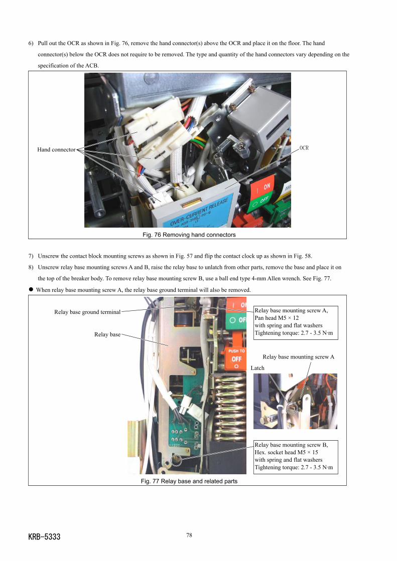
KRB-5333 78
6) Pull out the OCR as shown in Fig. 76, remove the hand connector(s) above the OCR and place it on the floor. The hand
connector(s) below the OCR does not require to be removed. The type and quantity of the hand connectors vary depending on the
specification of the ACB.
Fig. 76 Removing hand connectors
7) Unscrew the contact block mounting screws as shown in Fig. 57 and flip the contact clock up as shown in Fig. 58.
8) Unscrew relay base mounting screws A and B, raise the relay base to unlatch from other parts, remove the base and place it on
the top of the breaker body. To remove relay base mounting screw B, use a ball end type 4-mm Allen wrench. See Fig. 77.
When relay base mounting screw A, the relay base ground terminal will also be removed.
Fig. 77 Relay base and related parts
OCRHand connector
Latch
Relay base mounting screw A,Pan head M5 × 12with spring and flat washersTightening torque: 2.7 - 3.5 N·m
Relay base ground terminal
Relay base
Relay base mounting screw B,Hex. socket head M5 × 15with spring and flat washersTightening torque: 2.7 - 3.5 N·m
Relay base mounting screw A
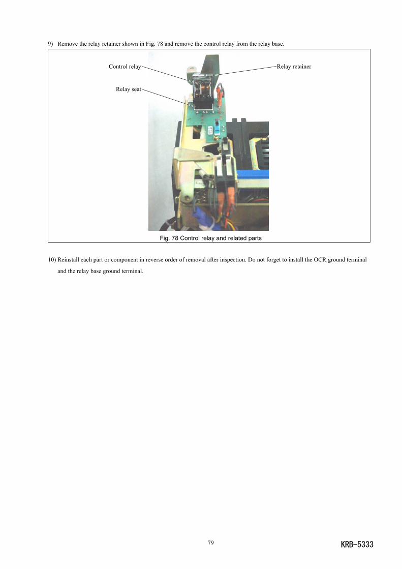
KRB-533379
9) Remove the relay retainer shown in Fig. 78 and remove the control relay from the relay base.
Fig. 78 Control relay and related parts
10) Reinstall each part or component in reverse order of removal after inspection. Do not forget to install the OCR ground terminal
and the relay base ground terminal.
Relay retainerControl relay
Relay seat
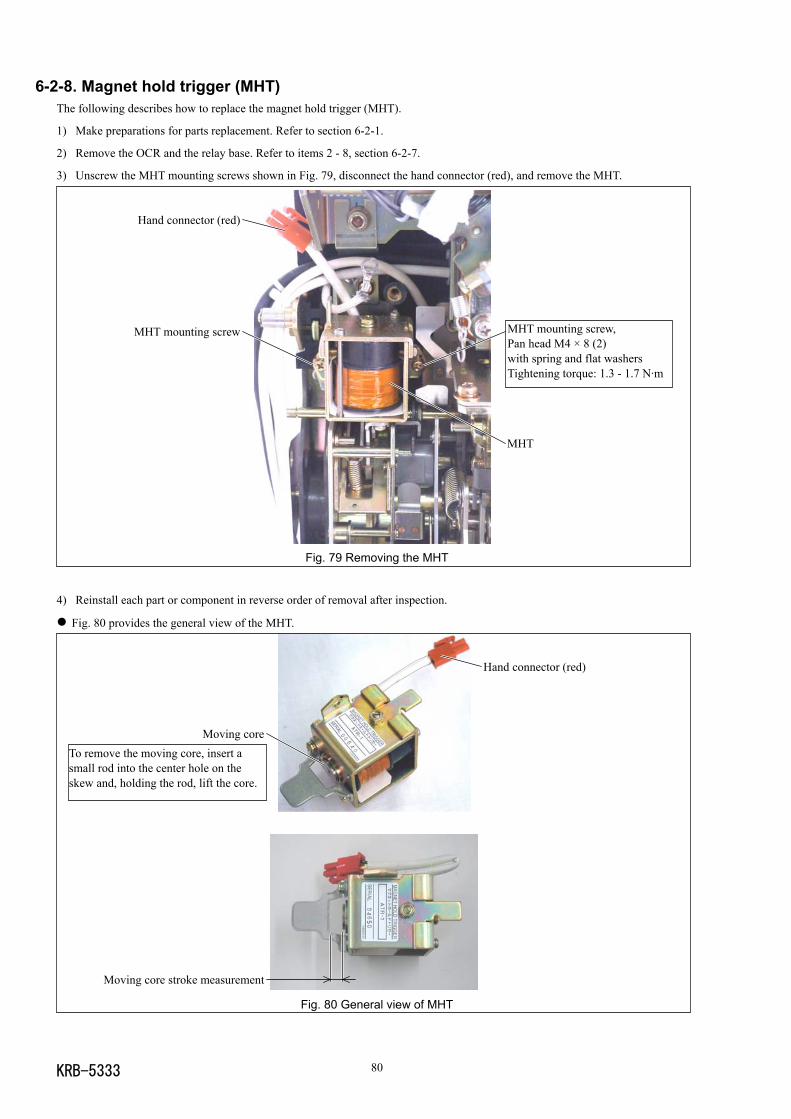
KRB-5333 80
6-2-8. Magnet hold trigger (MHT)The following describes how to replace the magnet hold trigger (MHT).
1) Make preparations for parts replacement. Refer to section 6-2-1.
2) Remove the OCR and the relay base. Refer to items 2 - 8, section 6-2-7.
3) Unscrew the MHT mounting screws shown in Fig. 79, disconnect the hand connector (red), and remove the MHT.
Fig. 79 Removing the MHT
4) Reinstall each part or component in reverse order of removal after inspection.
Fig. 80 provides the general view of the MHT.
Fig. 80 General view of MHT
MHT mounting screw,Pan head M4 × 8 (2)with spring and flat washersTightening torque: 1.3 - 1.7 N·m
Hand connector (red)
MHT mounting screw
MHT
Hand connector (red)
Moving core
Moving core stroke measurement
To remove the moving core, insert asmall rod into the center hole on theskew and, holding the rod, lift the core.
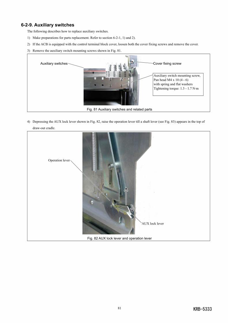
KRB-533381
6-2-9. Auxiliary switchesThe following describes how to replace auxiliary switches.
1) Make preparations for parts replacement. Refer to section 6-2-1, 1) and 2).
2) If the ACB is equipped with the control terminal block cover, loosen both the cover fixing screws and remove the cover.
3) Remove the auxiliary switch mounting screws shown in Fig. 81.
Fig. 81 Auxiliary switches and related parts
4) Depressing the AUX lock lever shown in Fig. 82, raise the operation lever till a shaft lever (see Fig. 83) appears in the top of
draw-out cradle.
Fig. 82 AUX lock lever and operation lever
AUX lock lever
Operation lever
Auxiliary switch mounting screw,Pan head M4 x 10 (4 - 6)with spring and flat washersTightening torque: 1.3 - 1.7 N·m
Auxiliary switches Cover fixing screw
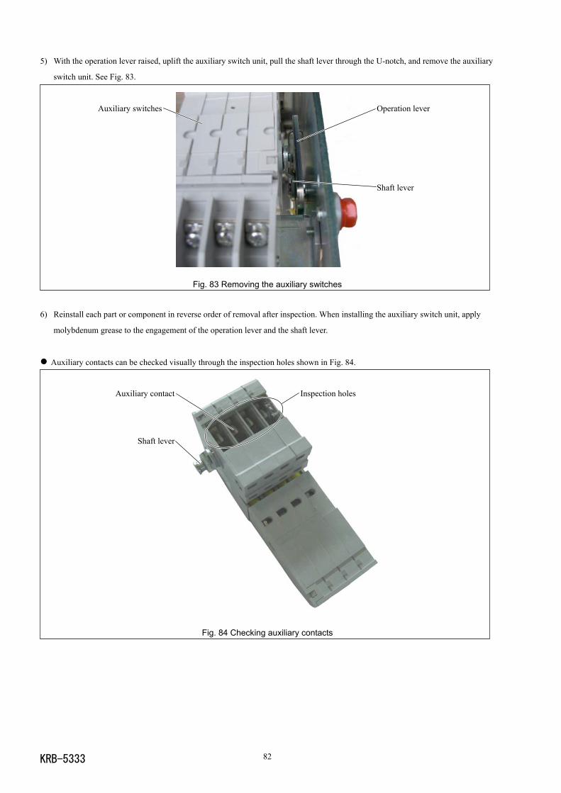
KRB-5333 82
Auxiliary contact
Shaft lever
Inspection holes
5) With the operation lever raised, uplift the auxiliary switch unit, pull the shaft lever through the U-notch, and remove the auxiliary
switch unit. See Fig. 83.
Fig. 83 Removing the auxiliary switches
6) Reinstall each part or component in reverse order of removal after inspection. When installing the auxiliary switch unit, apply
molybdenum grease to the engagement of the operation lever and the shaft lever.
Auxiliary contacts can be checked visually through the inspection holes shown in Fig. 84.
Fig. 84 Checking auxiliary contacts
Operation lever
Shaft lever
Auxiliary switches
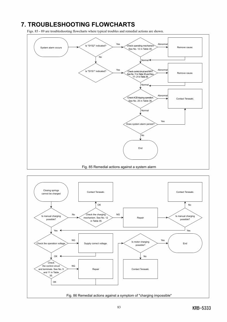
KRB-533383
7. TROUBLESHOOTING FLOWCHARTSFigs. 85 - 89 are troubleshooting flowcharts where typical troubles and remedial actions are shown.
Fig. 85 Remedial actions against a system alarm
Fig. 86 Remedial actions against a symptom of "charging impossible"
Closing springscannot be charged
Is manual chargingpossible?
Yes
Check the operation voltage.
OK
Checkthe control circuit
and terminals. See No. 5and 11 in Table
35.
OK
No
NG
NG
Contact Terasaki.
OK
Check the chargingmechanism. See No. 12
in Table 35.
Supply correct voltage.
Repair
NGRepair
Is motor chargingpossible?
No
Contact Terasaki.
Yes
Contact Terasaki.
No
Is manual chargingpossible?
Yes
End
System alarm occursIs "SYS2" indicated?
No
Is "SYS1" indicated?
Yes
Yes
Check operating mechanismSee No. 12 in Table 35.
Normal
Check control circuit and MHT.See No. 11 in Table 35 and Nos.
17– 21 in Table 36.
Normal
Check ACB tripping operation.See No. 25 in Table 36.
Normal
Does system alarm persist?
No
End
Abnormal
Abnormal
Abnormal
Yes
Remove cause.
Remove cause.
Contact Terasaki.
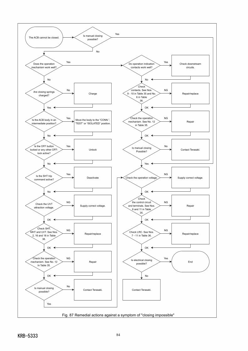
KRB-5333 84
Fig. 87 Remedial actions against a symptom of "closing impossible"
The ACB cannot be closed.
Does the operationmechanism work well?
No
Are closing springscharged?
Yes
Is the ACB body in anintermediate position?
No
Is the OFF buttonlocked or any other OFF-
lock active?
No
Is the SHT tripcommand active?
No
Check the UVTattraction voltage.
OK
Check SHT,MHT and UVT. See Nos.
2, 16 and 18 in Table36.
OK
Check the operationmechanism. See No. 12
In Table 35.
OK
Is manual closingpossible?
Yes
Yes
No
Yes
Yes
Yes
NG
NG
NG
No
Is manual closingpossible?
No
Charge
Move the body to the “CONN.”,“TEST” or “ISOLATED” position.
Unlock
Deactivate
Supply correct voltage.
Repair/replace
Repair
Contact Terasaki.
Yes
Do operation indicationcontacts work well?
No
Checkcontacts. See Nos.
9 - 10 in Table 35 and No.6 in Table
36.
OK
Check the operationmechanism. See No. 12
in Table 35.
OK
Is manual closingPossible?
Yes
Check the operation voltage.
OK
Checkthe control circuit
and terminals. See Nos.6 and 11 in Table
35.
OK
Check LRC. See Nos.7 - 11 in Table 36.
OK
Is electrical closingpossible?
No
Contact Terasaki.
Yes
NG
NG
No
NG
NG
NG
Yes
Check downstreamcircuits.
Repair/replace
Repair
Contact Terasaki.
Supply correct voltage.
Repair
Repair/replace
End
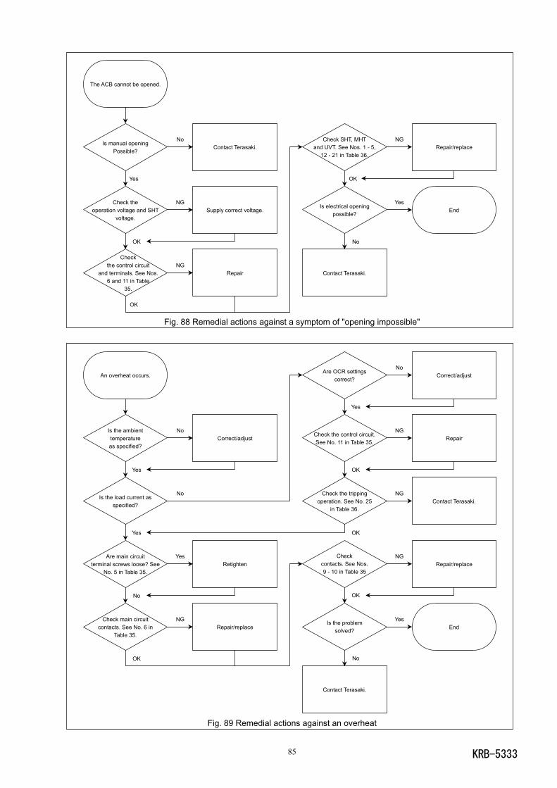
KRB-533385
Fig. 88 Remedial actions against a symptom of "opening impossible"
Fig. 89 Remedial actions against an overheat
An overheat occurs.
Is the ambienttemperatureas specified?
Yes
Is the load current asspecified?
Yes
Are main circuitterminal screws loose? See
No. 5 in Table 35.
No
Check main circuitcontacts. See No. 6 in
Table 35.
OK
No
No
Yes
NG
Correct/adjust
Retighten
Repair/replace
Are OCR settingscorrect?
Yes
Check the control circuit.See No. 11 in Table 35.
OK
Check the trippingoperation. See No. 25
in Table 36.
OK
Checkcontacts. See Nos.9 - 10 in Table 35
OK
Is the problemsolved?
No
Contact Terasaki.
No
NG
NG
NG
Yes
Correct/adjust
Repair
Contact Terasaki.
Repair/replace
End
The ACB cannot be opened.
Is manual openingPossible?
Yes
Check theoperation voltage and SHT
voltage.
OK
Checkthe control circuit
and terminals. See Nos.6 and 11 in Table
35.
OK
No
NG
NG
Contact Terasaki.
Supply correct voltage.
Repair
Check SHT, MHTand UVT. See Nos. 1 - 5,
12 - 21 in Table 36.
OK
Is electrical openingpossible?
No
Contact Terasaki.
NG
Yes
Repair/replace
End

KRB-5333 86

KRB-533387
Circuit Breaker Division7-2-10 Kamihigashi, Hiranoku, Osaka 547-0002, Japan
Tel: 81-6-6791-9323 Fax: 81-6-6791-9274
Web Site: www.terasaki.co.jp E-mail: [email protected]
Published in December 2008
The contents of this manual may be subject to change without notice.
Recycle paper used.