Embed Size (px)
Citation preview

THURLBY THANDAR INSTRUMENTS
QL355, QL355P, QL564 & QL564P PRECISION LINEAR POWER SUPPLIES
INSTRUCTION MANUAL
Table of Contents Introduction 2 Specification 4 EMC 7 Safety 8 Installation 9 Connections 10 Initial Operation 12 Manual Operation 14 Remote Operation (QL355P & QL564P only) 21 Remote Commands 30 Maintenance 33 Instructions en Francais Sécurité 34 Installation 35 Connexions 37 Utilisation initiale 39 Fonctionnement manuel 42 Maintenance 49 Bedienungsanleitung auf Deutsch Sicherheit 50 Vorbereitung des Geräts 51 Anschlüsse 53 Erstmalige Inbetriebnahme 55 Manueller Betrieb 58 Wartung 65 Istruzioni in Italiano Sicurezza 66 Installazione 67 Collegamenti 69 Primo utilizzo 70 Funzionamento in manuale 73 Manutenzione 80 Instrucciones en Español Seguridad 81 Instalación 82 Conexiones 84 Funcionamiento inicial 86 Funcionamiento manual 89 Mantenimiento 96
1
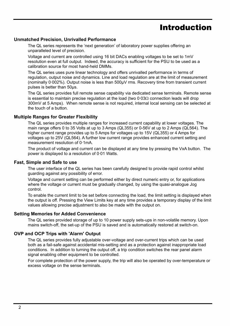
Introduction Unmatched Precision, Unrivalled Performance
The QL series represents the ‘next generation’ of laboratory power supplies offering an unparalleled level of precision. Voltage and current are controlled using 16 bit DACs enabling voltages to be set to 1mV resolution even at full output. Indeed, the accuracy is sufficient for the PSU to be used as a calibration source for most hand-held DMMs. The QL series uses pure linear technology and offers unrivalled performance in terms of regulation, output noise and dynamics. Line and load regulation are at the limit of measurement (nominally 0·002%). Output noise is less than 500µV rms. Recovery time from transient current pulses is better than 50µs. The QL series provides full remote sense capability via dedicated sense terminals. Remote sense is essential to maintain precise regulation at the load (two 0·03Ω connection leads will drop 300mV at 5 Amps). When remote sense is not required, internal local sensing can be selected at the touch of a button.
Multiple Ranges for Greater Flexibility The QL series provides multiple ranges for increased current capability at lower voltages. The main range offers 0 to 35 Volts at up to 3 Amps (QL355) or 0-56V at up to 2 Amps (QL564). The higher current range provides up to 5 Amps for voltages up to 15V (QL355) or 4 Amps for voltages up to 25V (QL564). A further low current range provides enhanced current setting and measurement resolution of 0·1mA. The product of voltage and current can be displayed at any time by pressing the VxA button. The power is displayed to a resolution of 0·01 Watts.
Fast, Simple and Safe to use The user interface of the QL series has been carefully designed to provide rapid control whilst guarding against any possibility of error. Voltage and current setting can be performed either by direct numeric entry or, for applications where the voltage or current must be gradually changed, by using the quasi-analogue Jog control. To enable the current limit to be set before connecting the load, the limit setting is displayed when the output is off. Pressing the View Limits key at any time provides a temporary display of the limit values allowing precise adjustment to also be made with the output on.
Setting Memories for Added Convenience The QL series provided storage of up to 10 power supply sets-ups in non-volatile memory. Upon mains switch-off, the set-up of the PSU is saved and is automatically restored at switch-on.
OVP and OCP Trips with 'Alarm' Output The QL series provides fully adjustable over-voltage and over-current trips which can be used both as a fail-safe against accidental mis-setting and as a protection against inappropriate load conditions. In addition to turning the output off, a trip condition switches the rear panel alarm signal enabling other equipment to be controlled. For complete protection of the power supply, the trip will also be operated by over-temperature or excess voltage on the sense terminals.
2
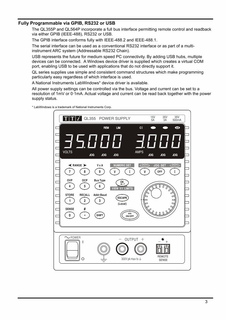
Fully Programmable via GPIB, RS232 or USB The QL355P and QL564P incorporate a full bus interface permitting remote control and readback via either GPIB (IEEE-488), RS232 or USB. The GPIB interface conforms fully with IEEE-488.2 and IEEE-488.1. The serial interface can be used as a conventional RS232 interface or as part of a multi-instrument ARC system (Addressable RS232 Chain). USB represents the future for medium speed PC connectivity. By adding USB hubs, multiple devices can be connected. A Windows device driver is supplied which creates a virtual COM port, enabling USB to be used with applications that do not directly support it. QL series supplies use simple and consistent command structures which make programming particularly easy regardless of which interface is used. A National Instruments LabWindows* device driver is available. All power supply settings can be controlled via the bus. Voltage and current can be set to a resolution of 1mV or 0·1mA. Actual voltage and current can be read back together with the power supply status.
* LabWindows is a trademark of National Instruments Corp.
3
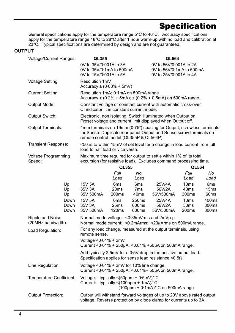
Specification General specifications apply for the temperature range 5°C to 40°C. Accuracy specifications apply for the temperature range 18°C to 28°C after 1 hour warm-up with no load and calibration at 23°C. Typical specifications are determined by design and are not guaranteed.
OUTPUT Voltage/Current Ranges: QL355 QL564
0V to 35V/0·001A to 3A 0V to 56V/0·001A to 2A 0V to 35V/0·1mA to 500mA 0V to 56V/0·1mA to 500mA 0V to 15V/0·001A to 5A 0V to 25V/0·001A to 4A
Voltage Setting: Resolution 1mV Accuracy ± (0·03% + 5mV)
Current Setting: Resolution 1mA; 0·1mA on 500mA range Accuracy ± (0·2% + 5mA); ± (0·2% + 0·5mA) on 500mA range.
Output Mode: Constant voltage or constant current with automatic cross-over. CI indicator lit in constant current mode.
Output Switch: Electronic, non isolating. Switch illuminated when Output on. Preset voltage and current limit displayed when Output off.
Output Terminals: 4mm terminals on 19mm (0·75”) spacing for Output; screwless terminals for Sense. Duplicate rear panel Output and Sense screw terminals on remote control model (QL355P & QL564P).
Transient Response: <50µs to within 15mV of set level for a change in load current from full load to half load or vice versa.
Voltage Programming Speed:
Maximum time required for output to settle within 1% of its total excursion (for resistive load). Excludes command processing time.
QL355 QL564 Full
Load No
Load Full
Load No
Load Up
Up Up
15V 5A 35V 3A 35V 500mA
6ms 20ms
200ms
6ms 7ms
40ms
25V/4A 56V/2A
56V/500mA
10ms 40ms
300ms
6ms 15ms 60ms
Down Down Down
15V 5A 35V 3A 35V 500mA
6ms 25ms
120ms
250ms 600ms 600ms
25V/4A 56V/2A
56V/500mA
10ms 50ms
200ms
400ms 800ms 800ms
Ripple and Noise (20MHz bandwidth):
Normal mode voltage: <0·35mVrms and 2mVp-p Normal mode current: <0·2mArms; <20µArms on 500mA range.
Load Regulation: For any load change, measured at the output terminals, using remote sense. Voltage <0·01% + 2mV. Current <0·01% + 250µA; <0.01% +50µA on 500mA range.
Add typically 2·5mV for a 0·5V drop in the positive output lead. Specification applies for sense lead resistance <0·5Ω.
Line Regulation: Voltage <0·01% + 2mV for 10% line change. Current <0·01% + 250µA; <0.01%+ 50µA on 500mA range.
Temperature Coefficient: Voltage: typically <(50ppm + 0·5mV)/°C Current: typically <(100ppm + 1mA)/°C; (100ppm + 0·1mA)/°C on 500mA range.
Output Protection: Output will withstand forward voltages of up to 20V above rated output voltage. Reverse protection by diode clamp for currents up to 3A.
4
Over-voltage Protection: (OVP)
Range 1V to 40V (QL355), 1V to 62V (QL564) Resolution 0·1V; accuracy ± (2% + 0·5V) Response time typically 100µs
Over-current Protection: (OCP)
Range 0·01A to 5·5A (QL355), 0·01A to 4·4A (QL564) Resolution 0·01A; accuracy ± (0·2% + 0·01A) Response time typically 35ms
Protection Functions: Output trips off for OVP, OCP, over-temperature and Sense miswiring.
METER SPECIFICATIONS Display Type: 5-digit (Volts), 4-digit (Amps), 14mm (0·56") LED. Voltage (CI mode): Resolution 10mV
Accuracy ± (0·1% of reading + 10mV) Current (CV mode): Resolution 0·001A; 0·1mA on 500mA range
Accuracy ± (0·2% + 0·005A); ± (0·2% + 0·5mA) on 500mA range V x A: Resolution 0·01W; 0·001W on 500mA range
Accuracy ± (0·3% + 0·05W); ± (0·3% + 0·005W) on 500mA range ALARM OUTPUT
Isolated rear-panel open-collector output signal. User can select output to be activated for either OVP, OCP, Overtemperature or Sense miswiring, or for any of those four faults.
KEYBOARD & ROTARY CONTROL All functions, including the selection and set-up of the remote control interfaces, can be set from the keyboard. The rotary jog control can be used to adjust output voltage and current settings in a quasi-analogue mode.
INTERFACES (QL355P & QL564P only) Full remote control facilities are available through the optional RS232, GPIB and USB interfaces. Setting and readback resolutions are the same as for the Output and Meter specifications respectively. RS232: Variable Baud rate, 19200 Baud maximum. 9-pin D-connector. Single
instrument or Addressable RS232 Chain (ARC) operation. IEEE-488: Conforming with IEEE488.1 and IEEE488.2 USB: Standard USB hardware connection. Remote Command Processing Time:
Typically <80ms between receiving the command terminator for a step voltage change at the instrument and the output voltage beginning to change.
GENERAL AC Input: 230V AC or 115V AC ± 10%, 50/60Hz. Installation Category II Power Consumption: 250VA max. Operating Range: +5ºC to +40ºC, 20% to 80% RH Storage Range: −40ºC to + 70ºC Environmental: Indoor use at altitudes up to 2000m, Pollution Degree 2. Cooling: Intelligent variable-speed fan.
Over-temperature trip shuts down output if internal temperatures exceed predetermined thresholds.
Store/Recall: Up to 10 set-ups can be saved and recalled via the keyboard or remote interfaces.
Safety: Complies with EN61010−1 EMC: Complies with EN61326 Size: 140 x 160 x 290mm (WxHxD), excluding feet and terminals. Weight: 5·5kg
5
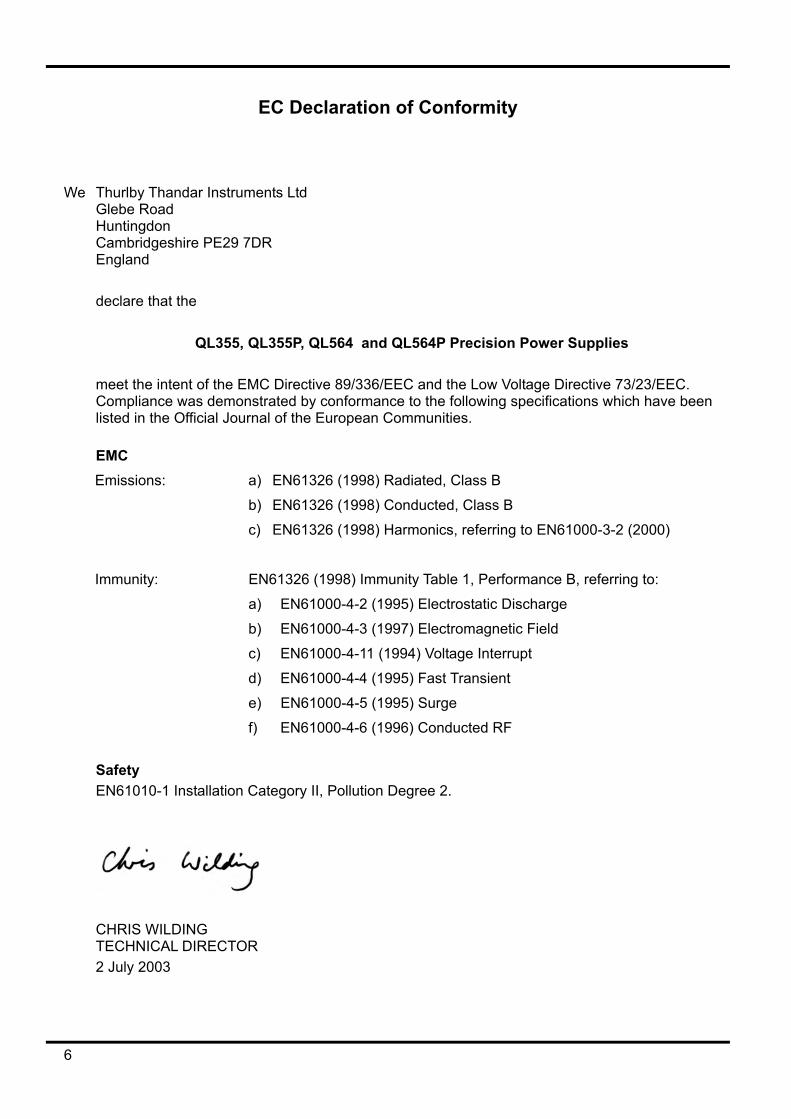
EC Declaration of Conformity
We Thurlby Thandar Instruments Ltd Glebe Road Huntingdon Cambridgeshire PE29 7DR England
declare that the
QL355, QL355P, QL564 and QL564P Precision Power Supplies meet the intent of the EMC Directive 89/336/EEC and the Low Voltage Directive 73/23/EEC. Compliance was demonstrated by conformance to the following specifications which have been listed in the Official Journal of the European Communities.
EMC Emissions: a) EN61326 (1998) Radiated, Class B
b) EN61326 (1998) Conducted, Class B
c) EN61326 (1998) Harmonics, referring to EN61000-3-2 (2000)
Immunity: EN61326 (1998) Immunity Table 1, Performance B, referring to:
a) EN61000-4-2 (1995) Electrostatic Discharge
b) EN61000-4-3 (1997) Electromagnetic Field
c) EN61000-4-11 (1994) Voltage Interrupt
d) EN61000-4-4 (1995) Fast Transient
e) EN61000-4-5 (1995) Surge
f) EN61000-4-6 (1996) Conducted RF Safety EN61010-1 Installation Category II, Pollution Degree 2.
CHRIS WILDING TECHNICAL DIRECTOR 2 July 2003
6
EMC This instrument has been designed to meet the requirements of the EMC Directive 89/336/EEC. Compliance was demonstrated by meeting the test limits of the following standards:
Emissions EN61326 (1998) EMC product standard for Electrical Equipment for Measurement, Control and Laboratory Use. Test limits used were: a) Radiated: Class B b) Conducted: Class B c) Harmonics: EN61000-3-2 (2000) Class A; the instrument is Class A by product category.
Immunity EN61326 (1998) EMC product standard for Electrical Equipment for Measurement, Control and Laboratory Use. Test methods, limits and performance achieved were: a) EN61000-4-2 (1995) Electrostatic Discharge : 4kV air, 4kV contact, Performance A. b) EN61000-4-3 (1997) Electromagnetic Field, 3V/m, 80% AM at 1kHz, Performance A. c) EN61000-4-11 (1994) Voltage Interrupt, 1 cycle, 100%, Performance B. d) EN61000-4-4 (1995) Fast Transient, 1kV peak (AC line), 0·5kV peak (DC Outputs),
Performance B. e) EN61000-4-5 (1995) Surge, 0·5kV (line to line), 1kV (line to ground), Performance B. f) EN61000-4-6 (1996) Conducted RF, 3V, 80% AM at 1kHz (AC line only; DC Output
connections <3m not tested), Performance A. According to EN61326 the definitions of performance criteria are: Performance criterion A: ‘During test normal performance within the specification limits.’ Performance criterion B: ‘During test, temporary degradation, or loss of function or performance which is self-recovering’. Performance criterion C: ‘During test, temporary degradation, or loss of function or performance which requires operator intervention or system reset occurs.’ Where Performance B is stated it is because DC Output regulation may deviate beyond Specification limits under the test conditions. However, the possible deviations are still small and unlikely to be a problem in practice. Note that if operation in a high RF field is unavoidable it is good practice to connect the PSU to the target system using screened leads which have been passed (together) through an absorbing ferrite sleeve fitted close to the PSU terminals.
Cautions To ensure continued compliance with the EMC directive observe the following precautions: a) after opening the case for any reason ensure that all signal and ground connections are
remade correctly and that case screws are correctly refitted and tightened. b) In the event of part replacement becoming necessary, only use components of an identical
type, see the Service Manual.
7
Safety This power supply is a Safety Class I instrument according to IEC classification and has been designed to meet the requirements of EN61010-1 (Safety Requirements for Electrical Equipment for Measurement, Control and Laboratory Use). It is an Installation Category II instrument intended for operation from a normal single phase supply. This instrument has been tested in accordance with EN61010-1 and has been supplied in a safe condition. This instruction manual contains some information and warnings which have to be followed by the user to ensure safe operation and to retain the instrument in a safe condition. This instrument has been designed for indoor use in a Pollution Degree 2 environment in the temperature range 5°C to 40°C, 20% - 80% RH (non-condensing). It may occasionally be subjected to temperatures between +5°C and –10°C without degradation of its safety. Do not operate while condensation is present. Use of this instrument in a manner not specified by these instructions may impair the safety protection provided. Do not operate the instrument outside its rated supply voltages or environmental range.
WARNING! THIS INSTRUMENT MUST BE EARTHED Any interruption of the mains earth conductor inside or outside the instrument will make the instrument dangerous. Intentional interruption is prohibited. The protective action must not be negated by the use of an extension cord without a protective conductor. When the instrument is connected to its supply, terminals may be live and opening the covers or removal of parts (except those to which access can be gained by hand) is likely to expose live parts. The apparatus shall be disconnected from all voltage sources before it is opened for any adjustment, replacement, maintenance or repair. Capacitors inside the power supply may still be charged even if the power supply has been disconnected from all voltage sources but will be safely discharged about 10 minutes after switching off power. Any adjustment, maintenance and repair of the opened instrument under voltage shall be avoided as far as possible and, if inevitable, shall be carried out only by a skilled person who is aware of the hazard involved. If the instrument is clearly defective, has been subject to mechanical damage, excessive moisture or chemical corrosion the safety protection may be impaired and the apparatus should be withdrawn from use and returned for checking and repair. Make sure that only fuses with the required rated current and of the specified type are used for replacement. The use of makeshift fuses and the short-circuiting of fuse holders is prohibited. Do not wet the instrument when cleaning it. The following symbols are used on the instrument and in this manual:-
Earth (ground) terminal.
mains supply OFF.
l mains supply ON.
alternating current (ac)
direct current (dc)
8
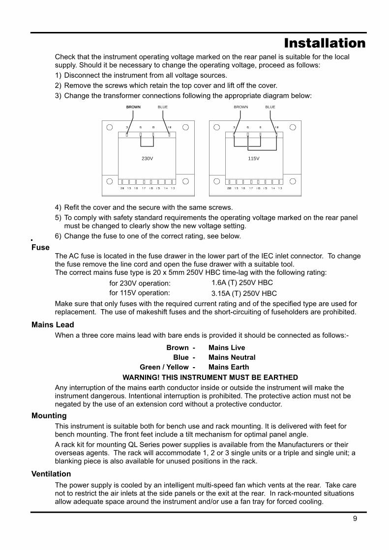
Installation Check that the instrument operating voltage marked on the rear panel is suitable for the local supply. Should it be necessary to change the operating voltage, proceed as follows: 1) Disconnect the instrument from all voltage sources. 2) Remove the screws which retain the top cover and lift off the cover. 3) Change the transformer connections following the appropriate diagram below:
BROWN BLUE BROWN BLUEBROWN
115V230V
4) Refit the cover and the secure with the same screws. 5) To comply with safety standard requirements the operating voltage marked on the rear panel
must be changed to clearly show the new voltage setting. 6) Change the fuse to one of the correct rating, see below.
Fuse The AC fuse is located in the fuse drawer in the lower part of the IEC inlet connector. To change the fuse remove the line cord and open the fuse drawer with a suitable tool. The correct mains fuse type is 20 x 5mm 250V HBC time-lag with the following rating:
for 230V operation: 1.6A (T) 250V HBC for 115V operation: 3.15A (T) 250V HBC
Make sure that only fuses with the required current rating and of the specified type are used for replacement. The use of makeshift fuses and the short-circuiting of fuseholders are prohibited.
Mains Lead When a three core mains lead with bare ends is provided it should be connected as follows:-
Brown - Mains Live Blue - Mains Neutral
Green / Yellow - Mains Earth WARNING! THIS INSTRUMENT MUST BE EARTHED
Any interruption of the mains earth conductor inside or outside the instrument will make the instrument dangerous. Intentional interruption is prohibited. The protective action must not be negated by the use of an extension cord without a protective conductor.
Mounting This instrument is suitable both for bench use and rack mounting. It is delivered with feet for bench mounting. The front feet include a tilt mechanism for optimal panel angle. A rack kit for mounting QL Series power supplies is available from the Manufacturers or their overseas agents. The rack will accommodate 1, 2 or 3 single units or a triple and single unit; a blanking piece is also available for unused positions in the rack.
Ventilation The power supply is cooled by an intelligent multi-speed fan which vents at the rear. Take care not to restrict the air inlets at the side panels or the exit at the rear. In rack-mounted situations allow adequate space around the instrument and/or use a fan tray for forced cooling.
9
Connections Front Panel Connections
The load should be connected to the positive (red) and negative (black) terminals marked OUTPUT. Remote sense connections to the load, if required, are made from the positive (+) and negative (−) REMOTE SENSE terminals. Remote sense operation is selected from the keyboard or via a remote control interface (QL355P & QL564P only); the REMOTE SENSE lamp is lit when remote sense is selected. Switching off remote sense returns the instrument to local sensing at the output terminals.
The terminal marked is connected to the chassis and safety earth ground.
Rear Panel Connections Output Terminals (QL355P & QL564P only)
The output and sense terminals are duplicated on the rear panel screw-terminal block marked Output +, Output −, Sense + and Sense − ; these connections are paralleled with their front panel equivalents. Remote sense operation is selected from the keyboard or via a remote control interface. When the rear panel terminals are used, remote sense should always be selected to ensure that output regulation is maintained within specification.
RS232 (QL355P & QL564P only) 9−pin D−connector compatible with addressable RS232 use. The pin connections are shown below:
Pin Name Description 1 − No internal Connection 2 TXD Transmitted data from instrument 3 RXD Received data to instrument 4 − No internal connection 5 GND Signal ground 6 − No internal connection 7 RXD2 Secondary received data 8 TXD2 Secondary transmitted data 9 GND Signal ground
Pin 2, 3 and 5 may be used as a conventional RS232 interface with XON/XOFF handshaking. Pins 7, 8 and 9 are additionally used when the instrument is used in addressable RS232 mode. Signal grounds are connected to instrument ground. The RS232 address is set from the keyboard.
GPIB (QL355P & QL564P only) The GPIB interface is not isolated; the GPIB signal grounds are connected to the instrument ground.
The implemented subsets are:
SH1 AH1 T6 TE0 L4 LE0 SR1 RL1 PP1 DC1 DT1 C0 E2
The GPIB address is set from the keyboard.
10
USB (QL355P & QL564P only) The USB port is connected to instrument ground. It accepts a standard USB cable. The Windows plug-and-play functions should automatically recognise that the instrument has been connected.
Alarm Outputs The recessed 2-pin connector marked Alarm provides access to an opto-isolated NPN switching transistor, the function of which can be set from the keyboard, see the Alarms section of this manual. The maximum operating voltage that can be applied across the terminals is 20VDC and the maximum sink current for the switch 'closure' is 1mA.
Do not apply external voltages between the terminals exceeding 30VDC.
11
Initial Operation This section of the manual is a general introduction to the controls and operation of the instrument and is intended to be read before using the power supply for the first time. In this manual front panel keys, connections and display indicators are shown in capitals, e.g. STORE, ESCAPE, OUTPUT, JOG. Messages shown on the 7-segment display are printed in a different type-font, e.g. StorE, GPIb, triP in upper or lower case to represent the characters as they are shown on the 7-segment display.
Switching On, Output On/Off The power switch is located at the bottom left of the front panel. At power-up the default behaviour is for the instrument's settings to be restored to those automatically saved when it was switched off, but with the Output always off. However, the user can change this default setting such that the Output is also restored at power-up to its status at power-down, see the Extra Functions section. The DC output is switched electronically with the ON/OFF key; the key illuminates when the output is on.
Keypad Only the principles of operation are outlined here; the setting of individual parameters is given in detail in later sections. The paramount consideration in designing the user interface has been to make changing settings as 'safe' as possible (i.e. with minimal risk of accidentally applying excessive voltages to a target system) whilst achieving ease of use. This has been achieved by requiring the user to confirm (OK) new numeric settings, with the option to ESCAPE at any point or even to simply pause until the operation times-out and the instrument returns to its orginal settings. In addition a buzzer, illuminated keys, LED indicators and display messages prompt, guide or warn the user such that entry or control errors are minimised. Where some of these features (e.g. beeps or flashing indicators) are considered unnecessary by regular users, the option exists to disable them, see the Extra Functions section. Under normal conditions the numeric keypad is disabled; pressing any key will cause the buzzer to make a double beep, indicating an illegal operation. To set a voltage or current with the keypad press the V or I NUMERIC SET key; the appropriate display shows 0·000V or 0·000A with the digit to the left of the decimal point flashing. Digits are entered in response to the flashing prompt, together with the decimal point at the appropriate time, and the entry is confirmed with the OK key. If OK is not pressed within 10 seconds of the last numeric key the entry is cancelled and the display returns to its original setting. If ESCAPE is pressed anywhere in the entry procedure, entry is cancelled and the display returns to its original setting. The OK key is used to confirm most keypad entries. At all other times it becomes the VIEW V/I LIMITS key and pressing it will cause the display to show preset output voltage and current limit for 3 seconds; during this period the LIM indicator in the display flashes. Pressing SHIFT illuminates the key and gives the numeric keys the functions marked above them (e.g. STORE, RECALL, etc.). When a function is selected by pressing one of these keys SHIFT is cancelled (the SHIFT key is no longer lit). The further key presses required to complete the selected function are described in detail in the sections that follow; if no key is pressed within 10 seconds to complete the function, the function with terminate as if ESCAPE has been pressed. SHIFT is a toggle key; pressing SHIFT again when it has been selected will cancel SHIFT. SHIFT is also cancelled by ESCAPE, or by pressing SET V or SET I.
12
Jog Control The rotary 'jog' control permits the output voltage or current limit to be incremented or decremented in steps with a resolution set by the JOG SET keys; the output immediately follows the setting, i.e. no OK is required. At power-up jog is always off. To jog the voltage or current setting press the V or I JOG SET key; the key will illuminate and the JOG indicator under the digit that was last jogged will flash. Whilst the V or I JOG SET key is lit, each further press of the V or I key moves the JOG indicator one digit to the left; the selection 'wraps-round' such that when the largest value of jog increment has been reached the next press returns it to the lowest. The default position at power-up is under the LSD, i.e. the lowest jog increment is selected. Turning the rotary jog control clockwise/anti-clockwise increments/decrements the selected digit; digits to the left of the one being jogged are automatically incremented/decremented when the decade overflow/underflow point is reached. Digits to the right of the one being jogged remain unchanged unless the jog step overflows/underflows the range maximum/minimum in which case they are set to zero. For example, 33·65V goes to 34·65V goes to 35·00V for the 35V range and a 1V jog increment; 0·160A goes to 0·060A goes to 0·001A for a 0·1A jog decrement. The jog steps that can be selected are 1mV, 10mV, 100mV and 1mA, 10mA, 100mA; if the 500mA range has been selected the current increment steps are 0·1mA, 1mA, 10mA. To disable the jog rotary control press the JOG SET OFF key; reselecting JOG SET V or I will enable jog on the last used digit position. Jog is not cancelled by using numeric entry or any of the SHIFT functions but it is disabled whilst that function is enabled. When in constant voltage mode with the output on the right-hand display will show actual current rather than current limit. If JOG SET I is selected the JOG indicator under the selected digit will flash at half-speed ('lazy' flash). To observe the effect of jogging the current limit it will be necessary to either turn the output off (so that the display permanently shows the current limit) or to press VIEW V/I LIMITS which causes the current limit to be displayed until 3 seconds after movement of the jog control ceases. The 'lazy' flash is also used when JOG SET V has been selected and actual voltage is being shown because the supply has gone into current limit. The factory default is to flash the JOG indicator under the selected digit for the whole time that jog is selected so that the user is constantly reminded which parameter can be incremented/ decremented. Where this degree of reminding is considered inadequate the user can select, using the Extra Functions capability, to flash the digit itself; conversely, where the flashing is considered intrusive the user can select to not flash the JOG indicator (except when the 'lazy' flash is shown).
Display The display shows the voltage on the left (5 digits) and the current on the right (4 digits). These 7-segment displays are also used to show prompts during the some of the function settings (e.g. memory store/recall or remote control address setting) using the limited 'character set' that can be achieved with a 7-segment display; these are necessarily a mixture of upper and lower case letters. Above and below the 7-segment display are several secret-until-lit annunciators. To the right, above the current display, are the indicators which show the selected operating range: 35V/3A, 15V/5A or 35V/500mA (QL355); 56V/2A, 25V/4A, 56V/500mA (QL564); the indicators light beneath the range printed immediately above them and, in the case of the 500mA range, the indicator is marked mA to emphasise that the current display is now showing mA. The other annunciators above the displays are: CI, indicating that the instrument is in constant current mode; LIM, which flashes when the VIEW V/I LIMITS key is pressed to show the set voltage/set current limit in the display; REM, which lights when the instrument is under control from a remote interface (QL355P & QL564P only). Below the three least significant digits of both the voltage and current displays are the JOG indicators; the appropriate indicator flashes when the jog function is being used, see the Jog Control section above.
13
Manual Operation New users should first read the Initial Operation chapter which describes the operating principles of the keypad and rotary jog control.
Set Voltage The left-hand display shows the set voltage to a resolution of 1mV, except when the instrument is in constant current (CI) mode. In CI mode the actual output voltage (which will be less than the set voltage) is shown and the display resolution is 10mV; the least significant digit (1mV resolution) is always displayed as a zero.
The voltage can be set directly from the numeric keypad: press the NUMERIC SET V key, enter the new value using the numeric keys and confirm by pressing OK. The broad principles of keypad entry are explained in the Initial Operation chapter, which should be read by new users.
When SET V is pressed the display shows 0·000; a new voltage is then entered (e.g. 12·345V is entered as 1, 2, ·, 3, 4, 5) and confirmed by OK. The position of the decimal point in the display is fixed to reduce the risk of entering a wrong value. As a consequence, and to avoid the need to enter leading zeroes (e.g. 2·345V is entered as 2, ·, 3, 4, 5, OK), numbers to the left of the decimal point are shown slightly differently to the numbers to the right of the decimal point during number entry; this is self-evident during number entry.
The minimum voltage setting is 0·000V; the maximum setting is 35·000V (15·000V on the 15V/5A range).
Pressing OK at any point will set the voltage entered with any remaining digits set to zero, e.g. 1, 2, ·, 3, OK will set 12·300V; 1, OK will set 1·000V; pressing OK immediately after SET V (while the display shows 0·000V) will set 0·000V.
Pressing ESCAPE at any time during the sequence, or making no further key press within 10 seconds of the previous one will cause the display to return to its original reading before SET V was pressed.
Entering a voltage outside the range maximum (including trying to enter 3 digits before the decimal point) or trying to enter more than 5 digits will cause the buzzer to beep twice; the last key entry will be ignored.
The voltage can also be set using the Jog control. Pressing JOG SET V will illuminate the V key and the JOG indicator under the digit that was last jogged will flash. Whilst the V key is lit, each further press will move the JOG indicator one digit to the left; the selection 'wraps round' such that when the largest value of jog increment has been reached the next press returns it to the lowest. The default position at power-up is under the LSD, i.e. the lowest jog increment is selected. The jog steps that can be selected are 1mV, 10mV and 100mV.
With jog enabled the output voltage can be incremented or decremented with the rotary jog control with a step resolution indicated by the position of the flashing JOG indicator. The output immediately follows the setting, i.e. no OK is required. If the output goes into constant current mode (indicated by the CI indicator flashing) the left-hand display shows actual voltage not set voltage. If JOG SET V is selected the JOG indicator under the selected digit will flash at half speed ('lazy' flash). To observe the effect of jogging the set voltage it will be necessary to either turn the output off (so that the display permanently shows the set voltage) or to press VIEW V/I LIMITS which causes the set voltage to be displayed until 3 seconds after movement of the jog control ceases.
Note that in constant current mode the actual voltage is measured and displayed to only 10mV resolution; the 1mV digit permanently displays zero.
Further details on the jog control can be found in the Initial Operation chapter.
14
Set Current Limit With the output off, the right-hand display shows the current limit to a resolution of 1mA (0·1mA on the 500mA range).
The current limit can be set directly from the numeric keypad: press the NUMERIC SET I key, enter the new value using the numeric keys and confirm by pressing OK. The broad principles of keypad entry are explained in the Initial Operation chapter, which should be read by new users.
When SET I is pressed the display shows 0·000; a new current is then entered (e.g. 1·234A is entered as 1, · , 2, 3, 4,) and confirmed by OK. The position of the decimal point in the display is fixed to reduce the risk of entering a wrong value. As a consequence, and to avoid the need to enter or display leading zeroes (e.g. 0·234A is entered as ·, 2, 3, 4, OK), numbers to the left of the decimal point are shown slightly differently to the numbers to the right of the decimal point during number entry; this is self-evident during number entry.
The minimum current setting is 0·001A (0·1mA on the 500mA range); the maximum setting is 3·000A, 5·000A or 500·0mA ( QL355), 2·000A, 4.000A or 500·0mA (QL564) according to range, i.e. there is no over-range capability.
Pressing OK at any point will set the current entered with any remaining digits set to zero, e.g. 1, ·, 2, OK will set 1·200A; 1, OK will set 1·000A; pressing OK immediately after SET V (while the display shows 0·000A) will set 0·001A.
Pressing ESCAPE at any time during the sequence, or making no key press within 10 seconds of the previous one will cause the display to return to its original reading before SET I was pressed.
Entering a value outside the range maximum (including trying to enter 2 digits before the decimal point) or trying to enter more than 4 digits will cause the buzzer to beep twice; the last key entry will be ignored.
The current limit can also be set using the rotary jog control. Pressing JOG SET I will illuminate the key and the JOG indicator under the digit that was last jogged will flash. Whilst the I key is lit, each further press will move the JOG indicator one digit to the left; the selection 'wraps round' such that when the largest value of jog increment has been reached the next press returns it to the lowest. The default position at power-up is under the LSD, i.e. the lowest jog increment is selected. The jog steps that can be selected are 1mA, 10mA and 100mA (0·1mA, 1mA and 10mA on the 500mA range).
With jog enabled the current limit can be incremented or decremented with the rotary jog control with a step resolution indicated by the position of the flashing JOG indicator. The output immediately follows the setting, i.e. no OK is required. With the output on the right-hand display shows actual current, not current limit (except in constant current mode). If JOG SET I is selected the JOG indicator under the selected digit will flash at half speed ('lazy' flash). To observe the effect of jogging the current limit it will be necessary to either turn the output off (so that the display permanently shows the current limit) or to press VIEW V/I LIMITS which causes the current limit to be displayed until 3 seconds after movement of the jog control ceases.
Instantaneous Current Output The current limit control can be set to limit the continuous output current to levels down to 1mA (0·1 mA on 500mA range). However, in common with all precision bench power supplies, a capacitor is connected across the output to maintain stability and good transient response. This capacitor charges to the output voltage and short-circuiting of the output will produce a current pulse as the capacitor discharges which is independent of the current limit setting.
15
Range Selection The instrument has three ranges: 35V/3A, 15V/5A and 35V/500mA (QL355); 56V/2A, 25V/4A and 56V/500mA (QL564). The selected range is shown by an illuminated indicator below the appropriate legend at the top right-hand side of the instrument; when the 500mA range is selected the indicator legend is mA to emphasise that the current meter now shows milliamps not amps.
To change range press SHIFT followed by RANGE or RANGE ; each press of RANGE selects the next range to the left; each press of RANGE selects the next range to the right; there is no 'wrap-round'. When the range is changed the indicator that represents the new range and the OK key both flash; pressing OK sets the new range. To exit without changing range press ESCAPE. Pressing any other key whilst in range change mode causes the warning buzzer to beep twice; no other action is taken. If OK is not pressed within 10 seconds of the last range change key press the range selection remains unchanged. The range can only be changed when the output is off. Pressing the RANGE or RANGE keys with the output on will cause the output ON/OFF key (as well as the OK key) to flash. The output may be turned off with the ON/OFF key and the range then changed by pressing OK, or OK may be pressed directly in which case the output is automatically turned off and the range then changed. If a range change causes a voltage or current limit setting to exceed the corresponding maximum of the new range the range change is accepted but the setting is made equal to the maximum of the new range. Note that the OVP setting is not changed when the range is changed (e.g. an OVP setting of 38V remains valid on the 15V range); it is left to the user to independently change the OVP setting if required.
Connection to the Load The load should be connected to the positive (red) and negative(black) OUTPUT terminals. Both are fully floating and either can be connected to ground.
Remote Sensing The instrument has a very low output impedance, but this is inevitably increased by the resistance of the connecting leads. At high currents this can result in significant differences between the indicated source voltage and the actual load voltage (two 20mΩ connecting leads will drop 0·2V at 5 Amps, for instance). This problem can be minimised by using short, thick, connecting leads, but where necessary it can be completely overcome by using the remote sense capability.
This requires the sense terminals to be connected to the output at the load instead of at the source; insert wires into the spring-loaded REMOTE SENSE terminals and connect directly to the load.
Select remote sense by pressing SHIFT, SENSE; the OK key flashes and the lamp above the remote sense terminals lights to show that remote sense will be selected when OK is pressed. Press OK to confirm; press ESCAPE to exit without changing state. Remote sense is turned off by pressing SHIFT, SENSE again; the OK key flashes and the remote sense lamp goes off to indicate that local sense will be restored when OK is pressed. Press OK to confirm; press ESCAPE to exit without changing state.
To avoid instability and transient response problems, care must be taken to ensure good coupling between each output and sense lead. This can be done either by twisting the leads together or by using coaxially screened cable (sense through the inner). An electrolytic capacitor directly across the load connection point may also be beneficial.
The voltage drop in each output lead must not exceed 0·5 Volts.
The QL355P/QL564P has rear panel output and sense terminals, appropriate for when the instrument is used in a rack. The rear panel sense terminals should always be used with the rear panel output connections.
16
Sense Miswiring Trip The output will be tripped off if the voltage between an output terminal and its corresponding sense terminal exceeds approximately 1V; this will happen if the sense wires are wired at the load to the wrong output or if an attempt is made to draw power from the sense wires.
If the sense terminals are miswired in this way the display shows the message SENSE triP and the output is turned off. Pressing ESCAPE at this point removes the message and the display now shows the preset voltage and current limit. When the cause of the trip has been corrected the output can be turned on again.
Series or Parallel Connection with Other Outputs The outputs of the power supply are fully floating and may be used in series with other power supply units to generate high DC voltages up to 300V DC.
The maximum permissible voltage between any terminal and earth ground ( ) is 300VDC.
WARNING! Such voltages are exceedingly hazardous and great care should be taken to shield the output terminals for such use. On no account should the output terminals be touched when the unit is switched on under such use. All connections to the terminals must be made with the power switched off on all units.
It should be noted that the unit can only source current and cannot sink it, thus units cannot be series connected in anti-phase.
The unit can be connected in parallel with others to produce higher currents. Where several units are connected in parallel, the output voltage will be equal to that of the unit with the highest output voltage setting until the current drawn exceeds its current limit setting, upon which the output will fall to that of the next highest setting, and so on. In constant current mode, units can be connected in parallel to provide a current equal to the sum of the current limit settings.
Note that the output terminals are rated at 15A maximum; if several outputs are operated in parallel to source higher currents than this the junction should be made at a separate point, not one of the terminals.
Over-Voltage Protection Over-Voltage Protection (OVP) can be set from 1·0V to 40V (QL355), 1·0V to 62V (QL564). If the output voltage exceeds the set OVP the output is immediately shut down (typically within 100µs), thus avoiding damage to the circuit under test. The OVP circuit will protect against accidental excessive voltage settings from the front panel or via the remote control interfaces, external voltages impressed across the output terminals, or a failure in the control circuitry of the instrument itself.
To set OVP press SHIFT, OVP; the 100mV step JOG indicator will start flashing and the jog rotary control can be used to increment/decrement the OVP setting in 100mV steps. Press OK to confirm the new setting; to exit without entering a new value press ESCAPE. The factory default setting is 40·0V (QL355), 62·0V (QL564).
If the OVP is tripped the display shows the message OUP triP and the output is turned off. Pressing ESCAPE at this point removes the message and the display now shows the preset voltage and current limit. When the cause of the OVP has been removed (or the OVP limit changed) the output can be turned on again.
Note that the OVP setting is not changed when the range is changed (e.g. an OVP setting of 38V remains valid on the 15V range); it is left to the user to independently change the OVP setting if required.
Note also that it is possible and valid to set OVP below the set voltage. If the supply is in constant current mode the output voltage will be below the set voltage; OVP could be set such that is was above the actual output voltage but below the set voltage. This could be used to trip the output under a fault condition which caused the load impedance to increase and the actual output voltage to therefore rise above the OVP point.
17
Over-Current Protection Over-Current Protection (OCP) can be set from 0·01A to 5·5A (QL355), 0·01A to 4·4A (QL564). If the output current exceeds the set OCP the output is shut down (typically within 35ms).
To set OCP press SHIFT, OCP; the 10mA step JOG indicator will start flashing and the jog rotary control can be used to increment/decrement the OCP setting in 10mA steps. Press OK to confirm the new setting; to exit without entering a new value press ESCAPE. The factory default setting is 5·50A.
If the OCP is tripped the display shows the message OCP triP and the output is turned off. Pressing ESCAPE at this point removes the message and the display now shows the preset voltage and current limit. When the cause of the OCP has been removed (or the OCP limit changed) the output can be turned on again.
Note that as with OVP, the OCP setting is not changed when the range is changed.
Note also that is possible and valid to set OCP below the set current limit. For example, the power supply may be used to repetitively test a unit under test (UUT) which normally takes a peak current of, say, 2 Amps. However, a faulty UUT would take a current of more than 2 Amps and would be damaged by being left in a 2 Amp current-limited state. In this case the current limit could be set to 2·1A, say, and the OCP set to 2·0A to ensure that a faulty UUT will trip the supply off.
Output Protection In addition to OVP and OCP for forward over-voltage and over-current protection, the output is protected from reverse voltages by a diode; the continuous reverse current must not exceed 3 Amps although transients can be much higher.
Output Power (V x A) If SHIFT, V x A is pressed the voltage display shows the product of measured output voltage x measured current and the current display shows UA. V x A is a momentary function, i.e. it gives an instantaneous, not a continuous, reading of the output power; the reading is held whilst the key is pressed. Pressing V x A cancels SHIFT. Jog is temporarily disabled (and the JOG indicators are turned off) during the V x A display.
Temperature Trip If the safe internal temperature limit is exceeded because, for example, the fan vents have been blocked, the output is turned off and the display will show OTP triP. Pressing ESCAPE at this point will do one of two things:
i. If the over-temperature condition has already cleared the message will be removed and the display will show preset voltage and current limit. Assuming the cause of the over-temperature has been rectified the output can be turned on again.
ii. If the instrument is still above the safe temperature limit the OTP triP message will flash slowly ('lazy' flash) until the instrument has cooled, at which point the display will show preset voltage and current limit again. Assuming the cause of the over-temperature has been rectified the output can be turned on again.
Alarm Output The recessed 2-pin connector on the rear panel is directly connected to an opto-coupled NPN switching transistor (pin 1 emitter, pin 2 collector) which is turned on (i.e. switch 'closure') according to the conditions specified in the Extra Functions section, see later. The default condition is switch closure for any trip condition (OVP, OCP, SENSE or OTP). The maximum open-circuit voltage permitted across the switch is 30VDC and the nominal sink current for switch closure is 1mA.
18
Store Settings The instrument can store 10 set-ups in non-volatile memory; the parameters stored are range, voltage, current limit, OVP and OCP. The output state and remote sense setting are not stored.
To store a set-up press SHIFT, STORE, store no., OK; the store no. is any key 0 to 9.
After key-presses SHIFT, STORE, the display shows StorE - ; the SHIFT function is cancelled (the light goes off). At this point, pressing any number key will display that number in place of the – and show either E (store Empty) or F (store Full) beside it, e.g. StorE 1.E, StorE 2.F . Any number of stores can be checked by pressing one number after another (i.e. without having to press SHIFT, STORE each time) before the selection is confirmed with the OK key. A full store can be overwritten with new settings. At any time before the OK key is pressed the store function can be exited without saving a set-up by pressing ESCAPE or by waiting 10 seconds from the last key entry.
Deleting Stored Settings Any store can be returned to 'empty' as follows: select the store by pressing SHIFT, STORE, store no.; at that point press · . The display now shows dELEt in place of StorE , e.g. dELEt 2.F ; pressing OK deletes the content of the store.
Recall Settings To recall a set-up press SHIFT, RECALL, store no., OK; the store no. is any key 0 to 9. After key-presses SHIFT, RECALL, the display shows rECAL – ; the SHIFT function is cancelled (the light goes off). At this point, pressing any key 0 to 9 will preview the voltage and current settings of that store number; the settings flash to indicate preview mode.
Any number of stores can be previewed by pressing one number after another (i.e. without having to press SHIFT, RECALL each time) before the selection is confirmed with the OK key. Empty stores are indicated by flashing – in every digit position. At any time before the OK key is pressed the Recall function can be exited without recalling a set-up by pressing ESCAPE or by waiting 10 seconds from the last key entry.
Settings may be recalled with the output on or off. However, if the recalled setting involves a range change the output is turned off to avoid any 'glitches'. After pressing SHIFT, RECALL, store no., the ON/OFF key will flash (as well as the OK key) if completing the recall involves a range change. The output may be turned off with the ON/OFF key and the recall then completed by pressing OK, or OK may be pressed directly in which case the output is automatically turned off and the recall completed.
Extra Functions Variations on some of the factory default functions can be set by the user by using the # extra functions facility. Each function change, detailed in the list below is accessed by pressing SHIFT, #, nn, when nn is the 2-digit number in the list below; the SHIFT light goes off and the buzzer gives a confirmation beep when the 2-digit number entry is complete.
# Code Function 00 Output always off at power-up (factory default)
01 Output status at power-up the same as at last power-down
20 Alarm output 'open' for Output off, 'closed' for Output on
21 (not used in single output PSU)
22 Alarm output 'closed' when over-temperature trip occurs
23 Alarm output 'closed' when sense trip occurs
24 Alarm output 'closed' when over-current trip occurs
19
25 Alarm output 'closed' when over-voltage trip occurs
26 Alarm output 'closed' when any trip occurs (factory default)
30 Buzzer off 31 Buzzer on (factory default). A single beep indicates confirmation, a double
beep indicates a wrong entry.
40 Jog digit flashes, JOG indicator only flashes when jog is 'hidden'
41 JOG indicator always flashes, except when 'hidden' (factory default)
42 JOG indicator doesn't flash, except when 'hidden' (lazy flash)
91 Loads default calibration parameters. Refer to Service Manual
92 Shows firmware version number in the display
93 Sets these # settings to their factory default
99 Enter calibration mode. Refer to Service Manual.
Factory Default Settings The ex-factory default settings (which will apply at first power-up) are as follows:
Range: 35V/3A (QL355); 56V/2A (QL564)
Voltage: 1·000V
Current Limit: 1·000A
OVP: 40V (QL355); 62V (QL564)
OCP: 5·5A (QL355); 4·4A (QL564)
Output: Output off; local Sense
# Settings: 00 Output always off at power-up
26 Alarm output 'closed' when any trip condition occurs
31 Buzzer on
41 JOG indicator always flashes; 'lazy' flash when hidden
RS232: 9,600 Baud (QL355P & QL564P only)
Address: 11 (QL355P & QL564P only)
Error Messages The following hardware errors are indicated by showing the appropriate error number in the display. The OK key will flash and if pressed the error will be ignored and operation will continue as described.
Error No. Error Description Action on pressing OK 1 Calibration constants corrupted at power-up Loads default calibration parameters 2 # functions corrupted at power-up Loads default # settings 3 Power-down settings not correctly loaded at
power up Loads factory default power-up settings
Switching the instrument off with the error message showing will leave all settings unchanged.
20
Remote Operation (QL355P & QL564P only) The instrument can be remotely controlled via its RS232, USB or GPIB interfaces. When using RS232 it can either be the only instrument connected to the controller or it can be part of an Addressable RS232 Chain (ARC) which permits up to 32 instruments to be addressed from one RS232 port. The USB interface operates internally through the instrument's RS232 interface. USB remote control consequently operates exactly as described for single-instrument RS232 use but via the USB connector. The instrument operates at the maximum Baud rate (19200) in USB mode. The virtual COM port on the controlling computer, which is set up using the driver software supplied, must be set to the same Baud rate. Application software on the computer can then access the instrument as if it is connected via the RS232 connector. The USB port cannot, however, be used as part of an Addressable RS232 Chain (ARC). Some of the following sections are general and apply to all modes (single instrument RS232, USB, ARC and GPIB); others are clearly only relevant to a particular interface or mode. It is only necessary to read the general sections plus those specific to the intended remote control mode. Remote command format and the remote commands themselves are detailed in the Remote Commands chapter.
Control Bus, Instrument Address and Baud Rate Selection For successful operation each instrument connected to a GPIB bus or addressable RS232 chain must be assigned a unique address. For addressable RS232 all instruments in the chain must be set to the same Baud rate. Press SHIFT, Bus Type to display the currently selected bus type. To change to another bus type scroll through the available types using the rotary control until the required type is displayed. Press OK to select the displayed type or ESCAPE to retain the previous selection. Press SHIFT, Addr/Baud to display the currently selected instrument bus address. If the currently selected bus type is RS232 then pressing Addr/Baud again displays the currently selected Baud rate and repeated presses alternate between the two. To change the address scroll through the available addresses using the rotary control when the address is displayed. The address can be set between 1 and 31 inclusive and the same address is used for both GPIB and addressable RS232; the address setting is ignored in USB mode. To change the Baud rate scroll through the available rates using the rotary control when the Baud rate is displayed. Press OK to select the last displayed address and Baud rate or ESCAPE to retain the previous selections. Note that RS232 must be selected before the Baud rate can be selected; the Baud rate is fixed at maximum (19200) for USB.
Remote/Local Operation At power-on the instrument will be in the local state with the REM indicator off. In this state all keyboard operations are possible. When the instrument is addressed to listen and a command is received the remote state will be entered and REM will be turned on. In this state the keyboard is locked out and remote commands only will be processed. The instrument may be returned to the local state by pressing the LOCAL key; however, the effect of this action will only remain until the instrument is addressed again or receives another character from the interface, when the remote state will once again be entered.
21
RS232 Interface RS232 Interface Connector
The 9-way D-type serial interface connector is located on the instrument rear panel. The pin connections are as shown below:
Pin Name Description 1 - No internal connection 2 TXD Transmitted data from instrument 3 RXD Received data to instrument 4 - No internal connection 5 GND Signal ground 6 - No internal connection 7 RXD2 Secondary received data (addressable RS232 only) 8 TXD2 Secondary transmitted data (addressable RS232 only) 9 GND Signal ground (addressable RS232 only)
Single Instrument RS232 Connections For single instrument remote control only pins 2, 3 and 5 are connected to the PC. However, for correct operation links must be made in the connector at the PC end between pins 1, 4 and 6 and between pins 7 and 8, see diagram. Pins 7 and 8 of the instrument must not be connected to the PC, i.e. do not use a fully wired 9–way cable.
Baud Rate is set as described above in Address and Baud Rate Selection; the other parameters are fixed as follows:
Start Bits: 1 Parity: None Data Bits: 8 Stop Bits: 1
Addressable RS232 Connections For addressable RS232 operation pins 7, 8 and 9 of the instrument connector are also used. Using a simple cable assembly, a 'daisy chain' connection system between any number of instruments, up to the maximum of 32 can be made, as shown below:
The daisy chain consists of the transmit data (TXD), receive date (RXD) and signal ground lines only. There are no control/handshake lines. This makes XON/XOFF protocol essential and allows the inter-connection between instruments to contain just 3 wires. The wiring of the adaptor cable is shown below:
22
All instruments on the interface must be set to the same baud rate and all must be powered on, otherwise instruments further down the daisy chain will not receive any data or commands. The other parameters are fixed as follows:
Start Bits: 1 Parity: None Data Bits: 8 Stop Bits: 1
RS232 Character Set Because of the need for XON/XOFF handshake it is possible to send ASCII coded data only; binary blocks are not allowed. Bit 7 of ASCII codes is ignored, i.e. assumed to be low. No distinction is made between upper and lower case characters in command mnemonics and they may be freely mixed. The ASCII codes below 20H (space) are reserved for addressable RS232 interface control. In this manual 20H, etc. means 20 in hexadecimal
Addressable RS232 (ARC) Interface Control Codes All instruments intended for use on the ARC bus use the following set of interface control codes. Codes between 00H and 1FH which are not listed here as having a particular meaning are reserved for future use and will be ignored. Mixing interface control codes inside instrument commands is not allowed except as stated below for CR and LF codes and XON and XOFF codes.
When an instrument is first powered on it will automatically enter the Non- Addressable mode. In this mode the instrument is not addressable and will not respond to any address commands. This allows the instrument to function as a normal RS232 controllable device. This mode may be locked by sending the Lock Non-Addressable mode control code, 04H. The controller and instrument can now freely use all 8 bit codes and binary blocks but all interface control codes are ignored. To return to addressable mode the instrument must be powered off.
To enable addressable mode after an instrument has been powered on the Set Addressable Mode control code, 02H, must be sent. This will then enable all instruments connected to the ARC bus to respond to all interface control codes. To return to Non-Addressable mode the Lock Non-Addressable mode control code must be sent which will disable addressable mode until the instruments are powered off.
Before an instrument is sent a command it must be addressed to listen by sending the Listen Address control code, 12H, followed by a single character which has the lower 5 bits corresponding to the unique address of the required instrument, e.g. the codes A-Z or a-z give the addresses 1-26 inclusive while @ is address 0 and so on. Once addressed to listen the instrument will read and act upon any commands sent until the listen mode is cancelled.
23
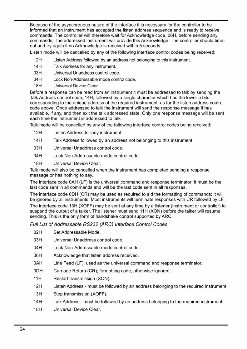
Because of the asynchronous nature of the interface it is necessary for the controller to be informed that an instrument has accepted the listen address sequence and is ready to receive commands. The controller will therefore wait for Acknowledge code, 06H, before sending any commands, The addressed instrument will provide this Acknowledge. The controller should time-out and try again if no Acknowledge is received within 5 seconds. Listen mode will be cancelled by any of the following interface control codes being received:
12H Listen Address followed by an address not belonging to this instrument. 14H Talk Address for any instrument. 03H Universal Unaddress control code. 04H Lock Non-Addressable mode control code. 18H Universal Device Clear.
Before a response can be read from an instrument it must be addressed to talk by sending the Talk Address control code, 14H, followed by a single character which has the lower 5 bits corresponding to the unique address of the required instrument, as for the listen address control code above. Once addressed to talk the instrument will send the response message it has available, if any, and then exit the talk addressed state. Only one response message will be sent each time the instrument is addressed to talk. Talk mode will be cancelled by any of the following interface control codes being received:
12H Listen Address for any instrument.
14H Talk Address followed by an address not belonging to this instrument.
03H Universal Unaddress control code.
04H Lock Non-Addressable mode control code.
18H Universal Device Clear. Talk mode will also be cancelled when the instrument has completed sending a response message or has nothing to say. The interface code 0AH (LF) is the universal command and response terminator; it must be the last code sent in all commands and will be the last code sent in all responses. The interface code 0DH (CR) may be used as required to aid the formatting of commands; it will be ignored by all instruments. Most instruments will terminate responses with CR followed by LF. The interface code 13H (XOFF) may be sent at any time by a listener (instrument or controller) to suspend the output of a talker. The listener must send 11H (XON) before the talker will resume sending. This is the only form of handshake control supported by ARC.
Full List of Addressable RS232 (ARC) Interface Control Codes 02H Set Addressable Mode.
03H Universal Unaddress control code.
04H Lock Non-Addressable mode control code.
06H Acknowledge that listen address received.
0AH Line Feed (LF); used as the universal command and response terminator.
0DH Carriage Return (CR); formatting code, otherwise ignored.
11H Restart transmission (XON).
12H Listen Address - must be followed by an address belonging to the required instrument.
13H Stop transmission (XOFF).
14H Talk Address - must be followed by an address belonging to the required instrument.
18H Universal Device Clear.
24
USB Interface The USB interface allows the instrument to be controlled using RS232 protocol via a computer’s USB port. This is useful where the computer’s standard RS232 COM ports are fully utilised or non-existent.
The instrument is supplied with a disk containing drivers for various versions of Windows, including Win98 and 2000. Any driver updates are available via the TTi website, www.tti-test.com. The disk also contains a text file with information and details of the software installation procedure.
Installation of the interface driver is achieved by connecting the instrument to a PC via a standard USB cable. The Windows’ plug and play functions should automatically recognise the addition of new hardware attached to the USB interface and if this is the first time the connection has been made, prompt for the location of a suitable driver. Provided that the standard Windows prompts are followed correctly Windows will install the appropriate driver and establish a virtual COM port within the PC. The number of the new COM port will depend upon the number of co-existing COM ports within the PC. The virtual COM port can be driven by Windows applications in exactly the same way as a standard port.
Note that it is necessary to set the virtual COM port to the same Baud rate as the instrument being controlled in exactly the same way as with a standard RS232 connection. The driver will remain installed on the PC so that the establishment of a virtual COM port is done automatically each time the instrument is connected to the PC via USB in the future. Further virtual COM ports are created for each additional instrument connected to the PC via USB. Each instrument is assigned a separate virtual COM port when it is first connected and the same COM port will be assigned each time that instrument is subsequently connected; the PC software makes use of the unique code embedded in each instrument to link it to the same virtual COM port irrespective of which physical USB port it is connected to. Use can also be made of the ADDRESS? command to easily identify which instrument is being controlled by a particular COM port. Although the addressing capability is ignored in USB operation the address can still be set and used as an identifier; set each USB-connected instrument to a different address and send the ADDRESS? command from each virtual COM port to confirm which instrument is connected to that port. The supplied disk contains an uninstall program should this be required.
GPIB Interface The GPIB interface 24-way connector is located on the instrument rear panel. The pin connections are as specified in IEEE Std. 488.1-1987 and the instrument complies with IEEE Std. 488.1-1987 and IEEE Std. 488.2-1987.
GPIB Subsets This instrument contains the following IEEE 488.1 subsets:
Source Handshake SH1 Acceptor Handshake AH1 Talker T6 Listener L4 Service Request SR1 Remote Local RL1 Parallel Poll PP1 Device Clear DC1 Device Trigger DT0 Controller C0 Electrical Interface E2
25
GPIB IEEE Std. 488.2 Error Handling – Query Error Register The IEEE 488.2 UNTERMINATED error (addressed to talk with nothing to say) is handled as follows. If the instrument is addressed to talk and the response formatter is inactive and the input queue is empty then the UNTERMINATED error is generated. This will cause the Query Error bit to be set in the Standard Event Status Register, a value of 3 to be placed in the Query Error Register and the parser to be reset. See the Status Reporting section for further information. The IEEE 488.2 INTERRUPTED error is handled as follows. If the response formatter is waiting to send a response message and a <PROGRAM MESSAGE TERMINATOR> has been read by the parser or the input queue contains more than one END message then the instrument has been INTERRUPTED and an error is generated. This will cause the Query Error bit to be set in the Standard Event Status Register, a value of 1 to be placed in the Query Error Register and the response formatter to be reset thus clearing the output queue. The parser will then start parsing the next <PROGRAM MESSAGE UNIT> from the input queue. See the Status Reporting section for further information.
The IEEE 488.2 DEADLOCK error is handled as follows. If the response formatter is waiting to send a response message and the input queue becomes full then the instrument enters the DEADLOCK state and an error is generated. This will cause the Query Error bit to be set in the Standard Event Status Register, a value of 2 to be placed in the Query Error Register and the response formatter to be reset thus clearing the output queue. The parser will then start parsing the next <PROGRAM MESSAGE UNIT> from the input queue. See the Status Reporting section for further information.
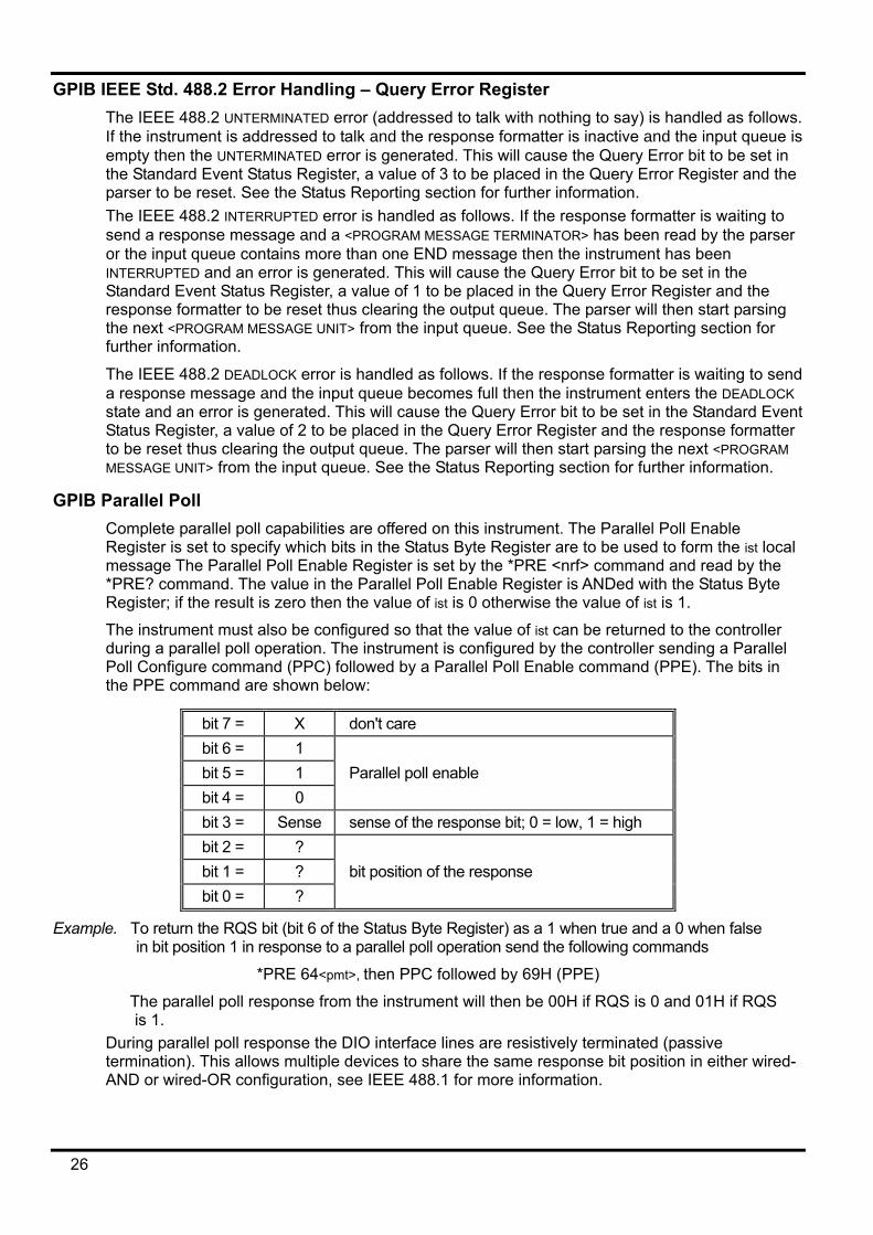
GPIB Parallel Poll Complete parallel poll capabilities are offered on this instrument. The Parallel Poll Enable Register is set to specify which bits in the Status Byte Register are to be used to form the ist local message The Parallel Poll Enable Register is set by the *PRE <nrf> command and read by the *PRE? command. The value in the Parallel Poll Enable Register is ANDed with the Status Byte Register; if the result is zero then the value of ist is 0 otherwise the value of ist is 1.
The instrument must also be configured so that the value of ist can be returned to the controller during a parallel poll operation. The instrument is configured by the controller sending a Parallel Poll Configure command (PPC) followed by a Parallel Poll Enable command (PPE). The bits in the PPE command are shown below:
bit 7 = X don't care bit 6 = 1 bit 5 = 1 Parallel poll enable bit 4 = 0 bit 3 = Sense sense of the response bit; 0 = low, 1 = high bit 2 = ? bit 1 = ? bit position of the response bit 0 = ?
Example. To return the RQS bit (bit 6 of the Status Byte Register) as a 1 when true and a 0 when false in bit position 1 in response to a parallel poll operation send the following commands
*PRE 64<pmt>, then PPC followed by 69H (PPE)
The parallel poll response from the instrument will then be 00H if RQS is 0 and 01H if RQS is 1.
During parallel poll response the DIO interface lines are resistively terminated (passive termination). This allows multiple devices to share the same response bit position in either wired-AND or wired-OR configuration, see IEEE 488.1 for more information.
26
Status Reporting This section describes the complete status model of the instrument. Note that some registers are specific to the GPIB section of the instrument and are of limited use in an RS232 environment.
Standard Event Status and Standard Event Status Enable Registers These two registers are implemented as required by the IEEE Std. 488.2. Any bits set in the Standard Event Status Register which correspond to bits set in the Standard Event Status Enable Register will cause the ESB bit to be set in the Status Byte Register.
The Standard Event Status Register is read and cleared by the *ESR? command. The Standard Event Status Enable register is set by the *ESE <nrf> command and read by the *ESE? command.
Bit 7 - Power On. Set when power is first applied to the instrument.
Bit 6 - Not used.
Bit 5 - Command Error. Set when a syntax type error is detected in a command from the bus. The parser is reset and parsing continues at the next byte in the input stream.
Bit 4 - Execution Error. Set when an error is encountered while attempting to execute a completely parsed command. The appropriate error number will be reported in the Execution Error Register.
1- 99 Indicates a hardware error has been encountered.
116 A recall of set up data has been requested but the store specified does not contain any data.
117 A recall of set up data has been requested but the store specified contains corrupted data. This indicates either a hardware fault or a temporary data corruption which can be corrected by writing data to the store again.
120 The numerical value sent with the command was too big or too small. Includes negative numbers where only positive numbers are accepted.
123 A recall/store of set up data has been requested from/to an illegal store number.
124 A range change has been requested but the current psu settings make it illegal – see manual operation instructions for details.
Bit 3 - Verify Timeout Error. Set when a parameter is set with 'verify' specified and the value is not reached within 5 secs, e.g. output voltage is slowed by a large capacitor on the output.
Bit 2 - Query Error. Set when a query error occurs. The appropriate error number will be reported in the Query Error Register as listed below.
1. Interrupted error
2. Deadlock error
3. Unterminated error
Bit 1 - Not used.
Bit 0 - Operation Complete. Set in response to the *OPC command.
Limit Event Status Register and Limit Event Status Enable Register These two registers are implemented as an addition to the IEEE Std.488.2. Their purpose is to inform the controller of entry to and/or exit from current or voltage limit conditions and the history of protection trip conditions since the last read.
Any bits set in the Limit Event Status Register which correspond to bits set in the Limit Event Status Enable Register will cause the LIM1 bit to be set in the Status Byte Register.
27
The Limit Event Status Register is read and cleared by the LSR1? command. The Limit Event Status Enable register is set by the LSE1<nrf> command and read by the LSE1? command.
Bit 7 - not used
Bit 6 - not used
Bit 5 - Set when an output sense trip has occurred
Bit 4 - Set when an output thermal trip has occurred
Bit 3 - Set when an output over current trip has occurred
Bit 2 - Set when an output over voltage trip has occurred
Bit 1 - Set when output enters current limit (constant current mode)
Bit 0 - Set when output enters voltage limit (constant voltage mode)
Status Byte Register and Service Request Enable Register
These two registers are implemented as required by the IEEE Std. 488.2. Any bits set in the Status Byte Register which correspond to bits set in the Service Request Enable Register will cause the RQS/MSS bit to be set in the Status Byte Register, thus generating a Service Request on the bus.
The Status Byte Register is read either by the *STB? command, which will return MSS in bit 6, or by a Serial Poll which will return RQS in bit 6. The Service Request Enable register is set by the *SRE <nrf> command and read by the *SRE? command.
Bit 7 - Not used.
Bit 6 - RQS/MSS. This bit, as defined by IEEE Std. 488.2, contains both the Requesting Service message and the Master Status Summary message. RQS is returned in response to a Serial Poll and MSS is returned in response to the *STB? command.
Bit 5 - ESB. The Event Status Bit. This bit is set if any bits set in the Standard Event Status Register correspond to bits set in the Standard Event Status Enable Register.
Bit 4 - MAV. The Message Available Bit. This will be set when the instrument has a response message formatted and ready to send to the controller. The bit will be cleared after the Response Message Terminator has been sent.
Bit 3 - Not used.
Bit 2 - Not used.
Bit 1 - Not used.
Bit 0 - LIM1. This will be set if any bits in the Limit Event Status register are set and corresponding bits are set in the Limit Event Status Enable register.
28
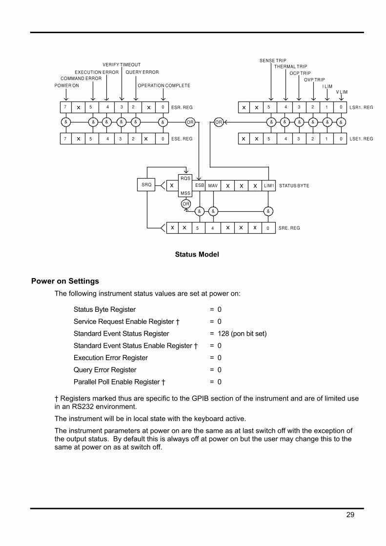
Status Model
Power on Settings The following instrument status values are set at power on:
Status Byte Register = 0
Service Request Enable Register † = 0
Standard Event Status Register = 128 (pon bit set)
Standard Event Status Enable Register † = 0
Execution Error Register = 0
Query Error Register = 0
Parallel Poll Enable Register † = 0
† Registers marked thus are specific to the GPIB section of the instrument and are of limited use in an RS232 environment.
The instrument will be in local state with the keyboard active.
The instrument parameters at power on are the same as at last switch off with the exception of the output status. By default this is always off at power on but the user may change this to the same at power on as at switch off.
29
Remote Commands RS232 Remote Command Formats
Serial input to the instrument is buffered in a 256 byte input queue which is filled, under interrupt, in a manner transparent to all other instrument operations. The instrument will send XOFF when approximately 200 characters are in the queue. XON will be sent when approximately 100 free spaces become available in the queue after XOFF was sent. This queue contains raw (un-parsed) data which is taken, by the parser, as required. Commands (and queries) are executed in order and the parser will not start a new command until any previous command or query is complete. In non–addressable RS232 mode responses to commands or queries are sent immediately; there is no output queue. In addressable mode the response formatter will wait indefinitely if necessary, until the instrument is addressed to talk and the complete response message has been sent, before the parser is allowed to start the next command in the input queue.
Commands must be sent as specified in the commands list and must be terminated with the command terminator code 0AH (Line Feed, LF). Commands may be sent in groups with individual commands separated from each other by the code 3BH (;). The group must be terminated with command terminator 0AH (Line Feed, LF).
Responses from the instrument to the controller are sent as specified in the commands list. Each response is terminated by 0DH (Carriage Return, CR) followed by 0AH (Line Feed, LF).
<WHITE SPACE> is defined as character codes 00H to 20H inclusive with the exception of those which are specified as Addressable RS232 (ARC) control codes.
<WHITE SPACE> is ignored except in command identifiers. e.g. '*C LS' is not equivalent to '*CLS'.
The high bit of all characters is ignored.
The commands are case insensitive.
GPIB Remote Command Formats GPIB input to the instrument is buffered in a 256 byte input queue which is filled, under interrupt, in a manner transparent to all other instrument operations. The queue contains raw (un-parsed) data which is taken, by the parser, as required. Commands (and queries) are executed in order and the parser will not start a new command until any previous command or query is complete. There is no output queue which means that the response formatter will wait, indefinitely if necessary, until the instrument is addressed to talk and the complete response message has been sent, before the parser is allowed to start the next command in the input queue.
Commands are sent as <PROGRAM MESSAGES> by the controller, each message consisting of zero or more <PROGRAM MESSAGE UNIT> elements separated by <PROGRAM MESSAGE UNIT SEPARATOR> elements.
A <PROGRAM MESSAGE UNIT> is any of the commands in the remote commands list.
A <PROGRAM MESSAGE UNIT SEPARATOR> is the semi-colon character ';' (3BH).
<PROGRAM MESSAGES> are separated by <PROGRAM MESSAGE TERMINATOR> elements which may be any of the following:
NL The new line character (0AH)
NL^END The new line character with the END message
^END The END message with the last character of the message
Responses from the instrument to the controller are sent as <RESPONSE MESSAGES>. A <RESPONSE MESSAGE> consists of one <RESPONSE MESSAGE UNIT> followed by a <RESPONSE MESSAGE TERMINATOR>.
A <RESPONSE MESSAGE TERMINATOR> is the new line character with the END message NL^END.
30
Each query produces a specific <RESPONSE MESSAGE> which is listed along with the command in the remote commands list. <WHITE SPACE> is ignored except in command identifiers. e.g. '*C LS' is not equivalent to '*CLS'. <WHITE SPACE> is defined as character codes 00H to 20H inclusive with the exception of the NL character (0AH). The high bit of all characters is ignored. The commands are case insensitive.
Command List This section lists all commands and queries implemented in this instrument. The commands are listed in alphabetical order within the function groups.
Note that there are no dependent parameters, coupled parameters, overlapping commands, expression program data elements or compound command program headers; each command is completely executed before the next command is started. All commands are sequential and the operation complete message is generated immediately after execution in all cases.
The following nomenclature is used:
<rmt> <RESPONSE MESSAGE TERMINATOR>
<nrf> A number in any format. e.g. 12, 12·00, 1·2 e1 and 120 e-1 are all accepted as the number 12. Any number, when received, is converted to the required precision consistent with the use then rounded up to obtain the value of the command.
<nr1> A number with no fractional part, i.e. an integer.
<nr2> A number in fixed point format e.g. 11·52, 0·78 etc.
The commands which begin with a * are those specified by IEEE Std. 488.2 as Common commands. All will function when used on the RS232 interface but some are of little use.
Instrument Specific Commands For commands specified as 'WITH VERIFY' the operation is completed when the parameter being adjusted reaches the required value to within ±5% or ±10 counts, whichever is the greater. If the value fails to settle within these limits within 5 seconds then the Verify Timeout bit (bit 3) is set in the Standard Event Status Register and the operation is completed at the end of the timeout period. The Operation Complete bit (bit 0) in the Standard Event Status Register is only ever set by the *OPC command. The *OPC (or the *OPC?) command can be used for device synchronisation due to the sequential nature of remote operations.
V1 <nrf> set the output to <nrf> Volts
V1V <nrf> set the output to <nrf> Volts with verify
OVP1 <nrf> set the output over voltage protection trip point to <nrf> Volts
I1 <nrf> set the output current limit to <nrf> Amps
OCP1 <nrf> set the output over current protection trip point to <nrf> Amps
V1? return the set voltage – response is V1 <nr2><rmt> where <nr2> is in Volts
I1? return the set current limit – response is I1 <nr2><rmt> where <nr2> is in Amps
OVP1? return the voltage trip setting – response is VP1 <nr2><rmt> where <nr2> is in Volts
OCP1? return the current trip setting – response is IP1 <nr2><rmt> where <nr2> is in Amps
V1O? return the output readback voltage – response is <nr2>V<rmt> where <nr2> is in Volts
31
I1O? return the output readback current – response is <nr2>A<rmt> where <nr2> is in Amps.
RANGE1 <nrf> set the voltage range to <nrf> where <nrf> has the following meaning: QL355P: 0=15V(5A), 1=35V(3A), 2=35V(500mA) QL564P: 0=25V(4A), 1=56V(2A), 2=56V(500mA)
RANGE1? return the set voltage range – response is R1 <nr1><rmt> where <nr1> has the following meaning: QL355P: 0=15V(5A), 1=35V(3A), 2=35V(500mA) QL564P: 0=25V(4A), 1=56V(2A), 2=56V(500mA)
DELTAV1 <nrf> set the output voltage step size to <nrf> Volts
DELTAI1 <nrf> set the output current step size to <nrf> Amps
DELTAV1? return the output voltage step size – response is DELTAV1 <nr2><rmt> where <nr2> is in Volts.
DELTAI1? return the output current step size – response is DELTAI1 <nr2><rmt> where <nr2> is in Amps.
INCV1 increment the output voltage by step size
INCV1V increment the output voltage by step size with verify
DECV1 decrement the output voltage by step size
DECV1V decrement output voltage by step size with verify
INCI1 increment the output current limit by step size
DECI1 decrement the output current limit by step size
OP1 <nrf> set output on/off where <nrf> has the following meaning: 0=OFF, 1=ON
SENSE1 <nrf> set output sense mode where <nrf> has the following meaning: 0=local, 1=remote
TRIPRST attempt to clear all trip conditions
LOCAL go to local
LSR1? query and clear LSR1, the limit status register − response is <nr1><rmt>
LSE1 <nrf> set the value of LSE1, the limit status enable register, to <nrf>
LSE1? return the value of LSE1, the limit status enable register - response is <nr1><rmt>
SAV1 <nrf> save the current PSU set up to the set-up store specified by <nrf> where <nrf> can be 0-9
RCL1 <nrf> recall a set up for the PSU from the set-up store specified by <nrf> where <nrf> can be 0-9
System and Status Commands *RST Resets the instrument to the factory default settings − (see Factory Defaults section)
with the exception of all remote interface settings. EER? Query and clear Execution Error Register. The response format is nr1<rmt>. QER? Query and clear Query Error Register. The response format is nr1<rmt> *CLS Clear Status. Clears the Standard Event Status Register, Query Error Register and
Execution Error Register. This indirectly clears the Status Byte Register. *ESE <nrf> Set the Standard Event Status Enable Register to the value of <nrf>. *ESE? Returns the value in the Standard Event Status Enable Register in <nr1> numeric
format. The syntax of the response is <nr1><rmt>
32
*ESR? Returns the value in the Standard Event Status Register in <nr1> numeric format. The register is then cleared. The syntax of the response is <nr1><rmt>
*IST? Returns ist local message as defined by IEEE Std. 488.2. The syntax of the response is 0<rmt>, if the local message is false, or 1<rmt>, if the local message is true.
*OPC Sets the Operation Complete bit (bit 0) in the Standard Event Status Register. This will happen immediately the command is executed because of the sequential nature of all operations.
*OPC? Query Operation Complete status. The syntax of the response is 1<rmt>. The response will be available immediately the command is executed because of the sequential nature of all operations.
*PRE <nrf> Set the Parallel Poll Enable Register to the value <nrf>. *PRE? Returns the value in the Parallel Poll Enable Register in <nr1> numeric format.
The syntax of the response is <nr1><rmt> *SRE <nrf> Set the Service Request Enable Register to <nrf>. *SRE? Returns the value of the Service Request Enable Register in <nr1> numeric format. The
syntax of the response is<nr1><rmt> *STB? Returns the value of the Status Byte Register in <nr1> numeric format. The syntax of the
response is<nr1><rmt> *WAI Wait for Operation Complete true. As all commands are completely executed before the
next is started this command takes no additional action.
Miscellaneous Commands *IDN? Returns the instrument identification. The exact response is determined by the
instrument configuration and is of the form <NAME>,<model>, 0, <version><rmt> where <NAME> is the manufacturer's name, <model> defines the type of instrument and <version> is the revision level of the software installed.
ADDRESS? Returns the bus address of the instrument. The syntax of the response is <nr1><rmt>. *TST? The PSU has no self test capability and the response is always 0 <rmt> *TRG The PSU has no trigger capability.
Calibration Specific Commands See Service Manual for details of calibration specific commands.
Error Messages Each error message has a number; only this number is reported via the remote control interfaces. Error message numbers are not displayed but are placed in the Execution Error Register where they can be read via the remote interfaces, see Status Reporting section.
Maintenance The Manufacturers or their agents overseas will provide a repair service for any unit developing a fault. Where owners wish to undertake their own maintenance work, this should only be done by skilled personnel in conjunction with the service manual which may be purchased directly from the Manufacturers or their agents overseas.
Cleaning If the instrument requires cleaning use a cloth that is only lightly dampened with water or a mild detergent. WARNING! TO AVOID ELECTRIC SHOCK, OR DAMAGE TO THE INSTRUMENT, NEVER ALLOW WATER TO GET INSIDE THE CASE. TO AVOID DAMAGE TO THE CASE NEVER CLEAN WITH SOLVENTS.
33
Sécurité Ce système alimentation est un instrument de classe de sécurité 1 conforme à la classification IEC et il a été conçu pour satisfaire aux exigences de la norme EN61010-1 (Exigences de sécurité pour les équipements électriques de mesure, de contrôle et d'utilisation en laboratoire). Il s'agit d'un instrument de Catégorie II d'installation devant être exploité depuis une alimentation monophasée standard. Cet instrument a été testé conformément à la norme EN61010-1 et il a été fourni en tout état de sécurité. Ce manuel d'instructions contient des informations et des avertissements qui doivent être suivis par l'utilisateur afin d'assurer un fonctionnement et un état en toute sécurité. Cet instrument a été conçu pour être utilisé en intérieur, en environnement de pollution de deuxième degré (Pollution degree 2) à des plages de températures de 5°C à 40°C, et à des taux d'humidité compris entre 20% et 80% (sans condensation). Il peut être soumis de temps à autre à des températures comprises entre +5°C et –10°C sans dégradation de sa sécurité. Ne pas l'utiliser en conditions de condensation. Toute utilisation de cet instrument de manière non spécifiée par ces instructions risque d'affecter sa protection de sécurité. Ne pas utiliser l'instrument hors des plages de tension d'alimentation nominale recommandées ni hors de ses tolérances d'environnement.
AVERTISSEMENT ! CET INSTRUMENT DOIT ETRE RELIE A LA TERRE Toute interruption du conducteur de la terre du secteur à l'intérieur ou à l'extérieur de l'instrument rendra l'instrument dangereux. Il est absolument interdit de priver intentionnellement l'instrument de son branchement à la terre. La sécurité de l'instrument ne doit pas être annulée par l'utilisation de rallonge sans conducteur de protection. Lorsque l'instrument est relié au secteur, il est possible que les bornes soient sous tension : l'ouverture des couvercles ou la dépose de pièces (à l'exception des pièces accessibles manuellement) risque de mettre à découvert des pièces sous tension. L'instrument doit être débranché du secteur et de toute source d'alimentationavant tout réglage, remplacement, travaux d'entretien ou de réparations. Les condensateurs qui se trouvent dans le bloc d'alimentation risquent de rester chargés, même si le bloc d'alimentation a été déconnecté de toutes les sources d'alimentation, mais ils se déchargeront en toute sécurité environ 10 minutes après extinction de l'alimentation. Eviter dans la mesure du possible d'effectuer des réglages, travaux de réparations ou d'entretien lorsque l'instrument ouvert est branché au secteur. Si cela s'avère toutefois indispensable, seul un technicien compétent connaissant les risques encourus doit effectuer ce genre de travaux. S'il est évident que l'instrument est défectueux, qu'il a été soumis à des dégâts mécaniques, à une humidité excessive ou à une corrosion chimique, la protection de sécurité est affaiblie : l'instrument doit être retiré de l'exploitation et renvoyé vérifications et de réparations. Ne remplacer les fusibles que par des fusibles d'intensité nominale requise et du type spécifié. Il est interdit d'utiliser des fusibles "maison" et de court-circuiter des porte-fusibles. Ne jamais humidifier l'instrument lors du nettoyage. Les symboles suivants se trouvent sur l'instrument, ainsi que dans ce manuel.
Borne de terre (masse)
l alimentation secteur ON (allumée)
courant continu (c.c.)
alimentation secteur OFF (éteinte)
courant alternatif (c.a.)
34
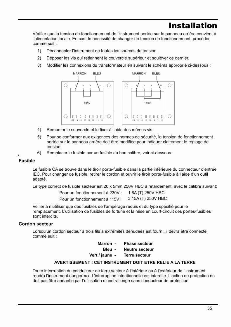
Installation Vérifier que la tension de fonctionnement de l’instrument portée sur le panneau arrière convient à l’alimentation locale. En cas de nécessité de changer de tension de fonctionnement, procéder comme suit :
1) Déconnecter l’instrument de toutes les sources de tension.
2) Déposer les vis qui retiennent le couvercle supérieur et soulever ce dernier.
3) Modifier les connexions du transformateur en suivant le schéma approprié ci-dessous :
4) Remonter le couvercle et le fixer à l’aide des mêmes vis.
5) Pour se conformer aux exigences des normes de sécurité, la tension de fonctionnement portée sur le panneau arrière doit être modifiée pour indiquer clairement le réglage de tension.
6) Remplacer le fusible par un fusible du bon calibre, voir ci-dessous.
Fusible
Le fusible CA se trouve dans le tiroir porte-fusible dans la partie inférieure du connecteur d’entrée IEC. Pour changer de fusible, retirer le cordon et ouvrir le tiroir porte-fusible à l’aide d’un outil adapté.
Le type correct de fusible secteur est 20 x 5mm 250V HBC à retardement, avec le calibre suivant: Pour un fonctionnement à 230V : 1.6A (T) 250V HBC Pour un fonctionnement à 115V : 3.15A (T) 250V HBC
Veiller à n’utiliser que des fusibles de l’ampérage requis et du type spécifié pour le remplacement. L’utilisation de fusibles de fortune et la mise en court-circuit des portes-fusibles sont interdits.
Cordon secteur Lorsqu’un cordon secteur à trois fils à extrémités dénudées est fourni, il devra être connecté comme suit :
Marron - Phase secteur Bleu - Neutre secteur
Vert / jaune - Terre secteur AVERTISSEMENT ! CET INSTRUMENT DOIT ETRE RELIE A LA TERRE
Toute interruption du conducteur de terre secteur à l’intérieur ou à l’extérieur de l’instrument rendra l’instrument dangereux. L’interruption intentionnelle est interdite. L’action de protection ne doit pas être anéantie par l’utilisation d’une rallonge sans conducteur de protection.
35
Montage Cet instrument convient à la fois à l’utilisation sur établi et au montage en baie. Il est livré avec des pieds pour le montage sur établi. Les pieds avant comprennent un mécanisme de basculement pour obtenir l’angle optimal du panneau. Un kit baie est disponible auprès des constructeurs ou de leurs agents à l’étranger pour le montage des unités d’alimentation électrique série QL. La baie acceptera 1, 2 ou 3 unités simples ou une unité triple et une simple ; une pièce d’obturation est également disponible pour les positions non-utilisées de la baie.
Ventilation
L’alimentation électrique est refroidie par un ventilateur intelligent à vitesses multiples qui ventile à l’arrière. Prendre soin de ne pas limiter les arrivées d’air sur les panneaux latéraux ou la sortie d’air à l’arrière. Dans les situations de montage en baie, laisser un espace adéquat autour de l’instrument et/ou utiliser un bloc ventilateur pour un refroidissement forcé.
36
Connexions Connexions du panneau avant
La charge devra être connectée aux bornes positive (rouge) et négative (noire) marquées OUTPUT (sortie). Les connexions de détection à distance sur la charge, si nécessaire, sont réalisées à partir des bornes positive (+) et négative (−) REMOTE SENSE (détection à distance). Le fonctionnement en détection à distance est sélectionné à partir du clavier ou par l’intermédiaire d’une interface de télécommande (QL355P & QL564P seulement) ; le témoin REMOTE SENSE est allumé lorsque la détection à distance est sélectionnée. Eteindre la détection à distance renvoie l’instrument à la détection locale sur les bornes de sortie.
La borne marquée est connectée au châssis et à la terre de sécurité.
Connexions du panneau arrière Bornes de sortie (QL355P & QL564P seulement)
Les bornes de sortie et de détection sont doublées sur le bornier à vis du panneau arrière avec les repères Output +, Output −, Sense + et Sense − ; ces connexions sont en parallèle avec leurs équivalents du panneau avant. Le fonctionnement en détection à distance est sélectionné à partir du clavier ou par l’intermédiaire d’une interface de télécommande. Si l’on utilise les bornes du panneau arrière, la détection à distance devra toujours être sélectionnée pour assurer que la régulation de sortie sera maintenue dans les spécifications.
RS232 (QL355P & QL564P seulement) Connecteur type D 9 broches compatible avec l’utilisation du RS232 adressable. La connexion des broches est indiquée ci-dessous :
Broche Nom Description 1 − Pas de connexion interne 2 TXD Données transmises par l’instrument 3 RXD Données reçues à l’instrument 4 − Pas de connexion interne 5 GND Terre du signal 6 − Pas de connexion interne 7 RXD2 Données secondaires reçues 8 TXD2 Données secondaires transmises 9 GND Terre du signal
Les broches 2, 3 et 5 peuvent être utilisées comme interface RS232 conventionnelle avec établissement de liaison XON/XOFF. Les broches 7, 8 et 9 sont en outre utilisées lorsque l’instrument est utilisé en mode RS232 adressable. Les terres de signaux sont connectées à la masse de l’instrument. L’adresse RS232 est réglée à partir du clavier.
GPIB (QL355P & QL564P seulement) L’interface GPIB n’est pas isolée ; les terres des signaux GPIB sont connectées à la masse de l’instrument.
Les sous-ensembles mis en œuvre sont :
SH1 AH1 T6 TE0 L4 LE0 SR1 RL1 PP1 DC1 DT1 C0 E2
L’adresse GPIB est réglée à partir du clavier.
37

USB (QL355P & QL564P seulement) Le port USB est connecté à la masse de l’instrument. Il accepte les câbles USB standard. Les fonctions "plug-and-play" de Windows devraient automatiquement reconnaître le fait que l’instrument a été connecté.
Sorties d’alarme Le connecteur à 2 broches en retrait marqué Alarm (alarme) donne accès à un transistor de basculement NPN opto-isolé, dont la fonction peut être réglée à partir du clavier, voir la section Alarmes de ce manuel.
La tension maximale de fonctionnement qui peut être appliquée entre les bornes est de 20V CC et l’intensité maximale absorbée pour la 'fermeture' de l’interrupteur est de 1mA.
Ne pas appliquer entre les bornes de tensions externes dépassant 30V CC.
38
Utilisation initiale Cette section du manuel est une introduction générale aux commandes et au fonctionnement de l’instrument et est censée être lue avant d’utiliser le générateur pour la première fois.
Dans ce manuel, les touches, connexions et indicateurs d’affichage du panneau avant sont présentés en lettres capitales, par ex. STORE (enregistrer), ESCAPE (échap.), OUTPUT (sortie), JOG (avance pas à pas). Les messages présentés sur l’afficheur à 7 segments sont imprimés dans une police différente, par ex. StorE, GPIb, triP en majuscules ou minuscules pour représenter les caractères tels qu’ils apparaissent sur l’afficheur à 7 segments.
Mise en marche, Marche/Arrêt de sortie L’interrupteur d’alimentation se trouve en bas à gauche du panneau avant.
A la mise sous tension, le comportement par défaut est la restauration des réglages de l’instrument qui ont été automatiquement sauvegardés à la mise hors tension, la Sortie étant toujours à l’arrêt. Cependant, l’utilisateur peut modifier ce réglage par défaut de telle sorte que la Sortie soit également restaurée à la mise sous tension à son état au moment de la mise hors-tension, voir la section Fonctions supplémentaires.
La sortie CC est commutée par un dispositif électronique avec la touche ON/OFF (marche/arrêt); cette touche s’allume lorsque la sortie est activée.
Clavier Seuls les principes de fonctionnement sont définis ici, le réglage des paramètres individuels est donné en détail dans les sections ultérieures.
La considération essentielle dans la conception de l’interface utilisateur a été de rendre les changements de réglages aussi 'sûrs' que possible (c’est à dire avec un risque minime d’appliquer accidentellement des tensions excessives à un système cible) tout en parvenant à la facilité d’utilisation. Ceci a été réalisé en demandant à l’utilisateur de confirmer (OK) les nouveaux réglages numériques, avec l’option ESCAPE pour s’échapper à tout moment ou même simplement marquer une pause jusqu’à ce que l’opération arrive à échéance et que l’instrument retourne à ses réglages d’origine.
De plus un bruiteur, des touches illuminées, des indicateurs à DEL et des messages à l’affichage invitent, guident ou avertissent l’utilisateur de façon à minimiser les erreurs de saisie ou de commande. Lorsque certaines de ces caractéristiques (par ex. bips ou indicateurs clignotants) sont considérées inutiles par les utilisateurs réguliers, il existe l’option de les désactiver, voir la section Fonctions supplémentaires.
Dans les conditions normales, le clavier numérique est désactivé ; le bruiteur émettra un double bip si l’on appuie sur une touche, indiquant une opération illégale. Pour régler la tension ou l’intensité avec le clavier, appuyer sur la touche NUMERIC SET V ou I (réglage numérique) ; l’affichage approprié donne 0,000V ou 0,000A, le chiffre à gauche de la virgule décimale clignotant. Les chiffres sont saisis en réponse à l’invite clignotante, ainsi que la virgule décimale au moment approprié, et la saisie est confirmée avec la touche OK. Si l’on n’appuie pas sur la touche OK dans les 10 secondes qui suivent l’utilisation de la dernière touche numérique, la saisie est annulée et l’affichage revient à sa présentation d’origine. Si l’on appuie sur ESCAPE n’importe où dans la procédure de saisie, la saisie est annulée et l’affichage revient à sa présentation d’origine.
La touche OK est utilisée pour confirmer la plupart des entrées au clavier. Le reste du temps, elle devient la touche VIEW V/I LIMITS (voir les limites V/I) et appuyer sur cette touche affichera la limite de tension et d’intensité de sortie préréglées pendant 3 secondes ; durant cette période, l’indicateur LIM clignote sur l’afficheur.
39
Appuyer sur SHIFT illumine la touche et donne accès aux fonctions marquées au-dessus des touches numériques (par ex. STORE, RECALL (rappeler), etc.). Lorsque l’on sélectionne une fonction en appuyant sur l’une de ces touches, SHIFT est annulé (la touche SHIFT n’est plus allumée). Les actions sur les autres touches nécessaires pour mener à bien la fonction sélectionnée sont décrites en détail dans les sections qui suivent ; si aucune touche n’est actionnée dans les 10 secondes pour réaliser la fonction, celle-ci prend fin comme si l’on avait appuyé sur ESCAPE. SHIFT est une touche à basculement : appuyer de nouveau sur SHIFT quand elle a été sélectionnée annule son effet. SHIFT est également annulé par ESCAPE, ou en appuyant sur SET V (régler V) ou SET I (régler I).
Commande pas à pas La commande rotative 'pas à pas' permet d’incrémenter ou de décrémenter la limite de tension ou d’intensité de sortie par pas avec une résolution réglée par les touches JOG SET (régler pas à pas) ; la sortie suit immédiatement le réglage, c’est à dire qu’il n’y a pas besoin de OK.
A la mise sous tension, la fonction pas à pas est toujours désactivée. Pour régler pas à pas la tension ou l’intensité, appuyer sur la touche JOG SET V ou I ; la touche s’illumine et l’indicateur JOG va clignoter sous le chiffre qui a été utilisé le dernier en pas à pas. Tant que la touche JOG SET V ou I est allumée, chaque nouvel appui sur la touche V ou I déplace l’indicateur JOG d’un chiffre sur la gauche ; la sélection 'tourne sur elle-même' de telle sorte que, quand la plus grande valeur d’incrément pas à pas a été atteinte, l’appui suivant la renvoie à la plus basse. La position par défaut à la mise sous tension est sous le chiffre le moins significatif, c’est à dire que le plus faible incrément pas à pas est sélectionné.
Tourner la molette rotative dans le sens horaire ou antihoraire incrémente ou décrémente le chiffre sélectionné ; les chiffres à gauche de celui qui est réglé pas à pas sont automatiquement incrémentés ou décrementés lorsque le point de passage à la dizaine supérieure ou inférieure est franchi. Les chiffres à droite de celui que l’on règle pas à pas restent inchangés jusqu’à ce que le réglage pas à pas franchisse le maximum ou le minimum de la plage, auquel cas ils sont réglés à zéro. Par exemple, 33,65V passe à 34,65V puis à 35,00V pour la plage 35V avec un incrément pas à pas de 1V ; 0,160A passe à 0,060A puis à 0,001A pour un décrément pas à pas de 0,1A.
Les pas de réglage que l’on peut sélectionner sont 1mV, 10mV, 100mV et 1mA, 10mA, 100mA; si la plage 500mA a été sélectionné, les pas d’incrémentation d’intensité seront 0,1mA, 1mA, 10mA.
Pour désactiver la molette rotative pas à pas, appuyer sur la touche JOG SET OFF (désactivation du pas à pas) ; resélectionner JOG SET V ou I permettra de revenir en pas à pas sur la position du dernier chiffre utilisé. Le pas à pas n’est pas annulé par l’utilisation de la saisie numérique ni par une des fonctions SHIFT, mais il est désactivé tant que cette fonction est activée.
Lorsque l’instrument est en mode de tension constante avec la sortie sur la droite, l’affichage montre l’intensité réelle plutôt que la limite d’intensité. Si on sélectionne JOG SET I, l’indicateur JOG va clignoter à mi-vitesse sous le chiffre sélectionné (clignotement 'paresseux'). Pour observer l’effet du réglage pas à pas de la limite d’intensité, il sera nécessaire soit de couper la sortie (de façon à ce que l’affichage montre de façon permanente la limite de sortie), soit appuyer sur VIEW V/I LIMITS, ce qui provoque l’affichage de la limite d’intensité encore 3 secondes après que le mouvement de la molette pas à pas cesse. Le clignotement 'paresseux' est également utilisé lorsque JOG SET V a été sélectionné et que la tension réelle est présentée parce que l’alimentation a atteint la limite d’intensité.
Le réglage par défaut d’usine est le clignotement de l’indicateur JOG sous le chiffre sélectionné tout le temps que le réglage pas à pas est sélectionné, de façon à rappeler constamment à l’utilisateur le paramètre qui peut être incrémenté ou décrémenté. Lorsque ce degré de rappel est considéré inadéquat, l’utilisateur pet sélectionner, à l’aide des Fonctions supplémentaires, de faire clignoter le chiffre lui-même ; à l’opposé, lorsque le clignotement est considéré intrusif, l’utilisateur peut choisir de ne pas faire clignoter l’indicateur JOG (excepté lorsque le clignotement 'paresseux' est utilisé).
40
Affichage L’affichage montre la tension sur la gauche (5 chiffres) et l’intensité sur la droite (4 chiffres). Ces affichages à 7 segments sont également utilisés pour présenter des invites lors de certains réglages de fonctions (par ex. l’enregistrement ou le rappel en mémoire ou le réglage d’adresses de télécommande) à l’aide du 'jeu de caractères' limité qui peut être obtenu avec un affichage à 7 segments ; il s’agit nécessairement d’un mélange de lettres majuscules et minuscules.
Au-dessus et au-dessous de l’affichage à 7 segments se trouvent plusieurs avertisseurs secrets jusqu’à ce qu’ils s’allument. Sur la droite, au-dessus de l’affichage d’intensité, se trouvent des indicateurs qui donnent la plage de fonctionnement sélectionnée : 35V/3A, 15V/5A ou 35V/500mA (QL355) ; 56V/2A, 25V/4A, 56V/500mA (QL564) ; les indicateurs s’allument sous la plage inscrite immédiatement au-dessus d’eux et, dans le cas de la plage 500mA, l’indicateur est marqué mA pour mettre l’accent sur le fait que l’affichage d’intensité est maintenant présenté en mA. Les autres avertisseurs au-dessus des affichages sont : CI, indiquant que l’instrument est en mode d’intensité constante ; LIM, qui clignote lorsque l’on actionne la touche VIEW V/I LIMITS pour voir la limite de tension/intensité réglée à l’affichage ; REM, qui s’allume lorsque l’instrument est sous le contrôle d’une interface distante (QL355P & QL564P seulement).
Au-dessous des trois chiffres les moins significatifs des affichages de tension et d’intensité, se trouvent les indicateurs JOG ; l’indicateur approprié clignote lorsque la fonction de réglage pas à pas est utilisée, voir la section Commande pas à pas ci-dessus.
41
Fonctionnement manuel Les nouveaux utilisateurs devront d’abord lire le chapitre Utilisation initiale qui décrit les principes de fonctionnement du clavier et de la molette de commande pas à pas.
Réglage de la tension L’affichage de gauche montre la tension réglée avec une résolution de 1mV, excepté quand l’instrument est en mode d’intensité constante (CI). En mode CI, la tension de sortie réelle (qui sera inférieure à la tension réglée) est indiquée, et la résolution d’affichage est de 10mV ; le chiffre le moins significatif (résolution 1mV) est toujours affiché sous forme d’un zéro. La tension peut être réglée directement à partir du clavier numérique : appuyer sur la touche NUMERIC SET V (réglage numérique de tension), entrer la nouvelle valeur à l’aide des touches numériques et confirmer en appuyant sur OK. Les grands principes de la saisie au clavier sont expliqués au chapitre Utilisation initiale, qui devra être lu par les nouveaux utilisateurs. Lorsque l’on appuie sur SET V, l’affichage donne 0,000 ; une nouvelle tension est alors saisie (par ex. 12,345V est saisi sous la forme 1, 2, ·, 3, 4, 5) et confirmé par OK. La position de la virgule décimale à l’affichage est fixe pour réduire le risque de saisir une mauvaise valeur. En conséquence, et pour éviter de devoir saisir les zéros non-significatifs (par ex. 2,345V est saisi sous la forme 2, ·, 3, 4, 5, OK), les nombres à gauche de la virgule décimale sont présentés de façon légèrement différente des nombres à droite de la virgule décimale lors de la saisie ; ceci est évident lors de la saisie des nombres. Le réglage minimum de tension est 0,000V ; le réglage maximum est 35,000V (15,000V sur la plage 15V/5A). Appuyer à n’importe quel moment sur OK programmera la tension saisie, tous les chiffres restant étant réglés à zéro, par ex. 1, 2, ·, 3, OK programmera 12,300V ; 1, OK programmera 1,000V ; appuyer sur OK immédiatement après SET V (tandis que l’affichage indique 0,000V) programmera 0,000V. Appuyer à n’importe quel moment sur ESCAPE au cours de la séquence, ou ne plus appuyer sur aucune touche pendant les 10 secondes qui suivent l’action précédente renverront l’affichage à sa lecture d’origine avant que la touche SET V ait été actionnée. Saisir une tension hors du maximum de la plage (y compris essayer de saisir 3 chiffres avant la virgule) ou essayer de saisir plus de 5 chiffres provoquera un double bip du bruiteur ; la dernière touche actionnée sera ignorée. La tension peut également être réglée à l’aide de la commande pas à pas. Appuyer sur JOG SET V va illuminer la touche V et l’indicateur JOG va clignoter sous le chiffre qui a été réglé pas à pas le dernier. Tant que la touche V est allumée, chaque appui suivant sur va déplacer l’indicateur JOG d’un chiffre sur la gauche ; la sélection 'tourne sur elle-même' de telle sorte que, quand la plus grande valeur d’incrément pas à pas a été atteinte, l’appui suivant la renvoie à la plus basse. La position par défaut à la mise sous tension est sous le chiffre le moins significatif, c’est à dire que le plus faible incrément pas à pas est sélectionné. Les pas qui peuvent être sélectionnés sont 1mV, 10mV et 100mV. La fonction pas à pas étant activée, la tension de sortie peut être incrémentée ou décrémentée avec la molette de commande pas à pas, avec une résolution de pas indiquée par la position de l’indicateur JOG clignotant. La sortie suit immédiatement le réglage, c’est à dire qu’il n’y pas besoin de valider par OK. Si la sortie passe en mode d’intensité constante (indiquée par l’indicateur CI clignotant) l’affichage de gauche montre la tension réelle et non la tension réglée. Si JOG SET V est sélectionné, l’indicateur JOG sous le chiffre sélectionné va clignoter à mi-vitesse (clignotement 'paresseux'). Pour observer l’effet du réglage pas à pas de la tension réglée, il sera nécessaire soit de couper la sortie (de façon à ce que l’affichage montre de façon permanente la tension réglée), soit d’appuyer sur VIEW V/I LIMITS, ce qui provoque l’affichage de la tension réglée encore 3 secondes après que le mouvement de la molette pas à pas cesse. Noter qu’en mode d’intensité constante, la tension réelle est mesurée et affichée à une résolution de seulement 10mV ; le chiffre 1mV affiche zéro de façon permanente. Davantage de détails sur la commande pas à pas sont donnés dans le chapitre Utilisation initiale.
42
Réglage de la limite d’intensité La sortie étant coupée, l’affichage de droite montre la limite d’intensité avec une résolution de 1mA (0,1mA sur la plage 500mA).
La limite d’intensité peut être réglée directement à partir du clavier numérique : appuyer sur la touche NUMERIC SET I (réglage numérique d’intensité), entrer la nouvelle valeur à l’aide des touches numériques et confirmer en appuyant sur OK. Les grands principes de la saisie au clavier sont expliqués au chapitre Utilisation initiale, qui devra être lu par les nouveaux utilisateurs.
Lorsque l’on appuie sur SET I, l’affichage donne 0,000 ; une nouvelle intensité est alors saisie (par ex. 1,234A est saisi sous la forme 1, ·, 2, 3, 4) et confirmé par OK. La position de la virgule décimale à l’affichage est fixe pour réduire le risque de saisir une mauvaise valeur. En conséquence, et pour éviter de devoir saisir les zéros non-significatifs (par ex. 0,234A est saisi sous la forme , · , 2, 3, 4, OK), les nombres à gauche de la virgule décimale sont présentés de façon légèrement différente des nombres à droite de la virgule décimale lors de la saisie ; ceci est évident lors de la saisie des nombres.
Le réglage minimum de tension est 0,001A (0,1mA sur la plage 500mA) ; le réglage maximum est 3,000A, 5,000A ou 500,0mA (QL355) ; 2,000A, 4,000A ou 500,0mA (QL564), selon la plage, c’est à dire qu’il n’y pas de capacité de dépassement de plage.
Appuyer à n’importe quel moment sur OK programmera l’intensité saisie, tous les chiffres restant étant réglés à zéro, par ex. 1, ·, 2, OK programmera 1,230A ; 1, OK programmera 1,000A ; appuyer sur OK immédiatement après SET I (tandis que l’affichage indique 0,000A) programmera 0,001A.
Appuyer à n’importe quel moment sur ESCAPE au cours de la séquence, ou ne plus appuyer sur aucune touche pendant les 10 secondes qui suivent l’action précédente renverront l’affichage à sa lecture d’origine avant que la touche SET I ait été actionnée.
Saisir une valeur hors du maximum de la plage (y compris essayer de saisir 2 chiffres avant la virgule) ou essayer de saisir plus de 4 chiffres provoquera un double bip du bruiteur ; la dernière touche actionnée sera ignorée.
La limite d’intensité peut également être réglée à l’aide de la commande pas à pas. Appuyer sur JOG SET I va illuminer la touche I et l’indicateur JOG va clignoter sous le chiffre qui a été réglé pas à pas le dernier. Tant que la touche I est allumée, chaque appui suivant sur va déplacer l’indicateur JOG d’un chiffre sur la gauche ; la sélection 'tourne sur elle-même' de telle sorte que, quand la plus grande valeur d’incrément pas à pas a été atteinte, l’appui suivant la renvoie à la plus basse. La position par défaut à la mise sous tension est sous le chiffre le moins significatif, c’est à dire que le plus faible incrément pas à pas est sélectionné. Les pas qui peuvent être sélectionnés sont 1mA, 10mA et 100mA (0,1mA, 1mA et 10mA sur la plage 500mA).
La fonction pas à pas étant activée, la limite d’intensité peut être incrémentée ou décrémentée avec la molette de commande pas à pas, avec une résolution de pas indiquée par la position de l’indicateur JOG clignotant. La sortie suit immédiatement le réglage, c’est à dire qu’il n’y pas besoin de valider par OK. La sortie sur l’affichage de droite indiquant l’intensité réelle, et non la limite d’intensité (excepté en mode d’intensité constante). Si JOG SET I est sélectionné, l’indicateur JOG sous le chiffre sélectionné va clignoter à mi-vitesse (clignotement 'paresseux'). Pour observer l’effet du réglage pas à pas de la limite d’intensité, il sera nécessaire soit de couper la sortie (de façon à ce que l’affichage montre de façon permanente la limite d’intensité), soit d’appuyer sur VIEW V/I LIMITS, ce qui provoque l’affichage de la limite d’intensité encore 3 secondes après que le mouvement de la molette pas à pas cesse.
43
Sortie d’intensité instantanée La commande de limite d’intensité peut être réglée pour limiter l’intensité de sortie continue à des niveaux descendant jusqu’à 1mA (0·1 mA sur la plage 500mA). Cependant, communément à tous les générateurs de précision d’établi, un condensateur est connecté sur la sortie pour conserver la stabilité et une bonne réponse aux défauts transitoires. Ce condensateur se charge sur la tension de sortie et une mise en court-circuit de la sortie produira une impulsion d’intensité à la décharge du condensateur, ce qui ne dépend pas du réglage de limite d’intensité.
Sélection des plages L’instrument possède trois plages : 35V/3A, 15V/5A et 35V/500mA (QL355); 56V/2A, 25V/4A et 56V/500mA (QL564). La plage sélectionnée est signalée par un indicateur lumineux sous la légende appropriée en haut à droite de l’instrument; quand on sélectionne la plage 500mA, la légende de l’indicateur est mA pour mettre l’accent sur le fait que l’ampèremètre indique maintenant des milliampères et non des Ampères.
Pour changer de plage, appuyer sur SHIFT suivi de RANGE ou RANGE (plage inférieure ou supérieure) ; chaque appui sur RANGE sélectionne la plage suivante sur la gauche ; chaque appui sur RANGE sélectionne la plage suivante sur la droite ; il n’y a pas 'd’enroulement sur elles-mêmes' de ces fonctions. Lorsque la plage change, l’indicateur qui représente la nouvelle plage et la touche OK clignotent ; appuyer sur OK programme la nouvelle plage. Pour quitter sans changer de plage, appuyer sur ESCAPE. Appuyer sur n’importe quelle autre clé tant que l’instrument est en mode de changement de plage provoquera l’émission de deux bips par le bruiteur ; aucune autre action n’est effectuée. Si l’on n’appuie pas sur OK dans les 10 secondes qui suivent le dernier appui sur la touche de changement de plage, la sélection de plage reste inchangée.
La plage ne peut être changée que quand la sortie est coupée. Appuyer sur les touches RANGE ou RANGE avec la sortie active fera clignoter la touche ON/OFF (marche/arrêt) de la sortie (ainsi que la touche OK). La sortie peut être coupée avec la touche ON/OFF et la plage peut alors être changée en appuyant sur OK, ou bien on pourra appuyer directement sur OK, auquel cas la sortie est automatiquement coupée, ce qui permet ensuite de changer de plage.
Si un changement de plage fait dépasser au réglage de tension ou de limite d’intensité le maximum correspondant de la nouvelle plage, le changement de plage est accepté mais le réglage est ramené à égalité avec le maximum de la nouvelle plage.
Noter que le réglage OVP (protection contre les surtensions) n’est pas modifié lorsque l’on change de plage (par ex. un réglage OVP de 38V reste valide sur la plage 15V) ; il appartient à l’utilisateur de modifier indépendamment le réglage OVP si nécessaire.
Connexion à la charge La charge devra être connectée aux bornes OUTPUT (sortie) positive (rouge) et négative (noire). Les deux sont entièrement flottantes et l’une ou l’autre peuvent être connectées à la masse.
Détection à distance L’instrument possède une très faible impédance de sortie, mais celle-ci est inévitablement augmentée par la résistance des fils de raccordement. A hautes intensités, ceci peut se traduire par des différences significatives entre la tension source indiquée et la tension réelle de la charge (deux fils de raccordement de 20mΩ chuteront de 0,2V à 5A, par exemple). Ce problème peut être minimisé en utilisant des fils de raccordement courts et épais, mais lorsque cela s’avère nécessaire, on peut le surmonter complètement en utilisant la capacité de détection à distance.
Ceci nécessite de connecter les bornes de détection à la sortie sur la charge plutôt que sur la source ; insérer les fils dans les bornes à ressort REMOTE SENSE (détection à distance) et les connecter directement à la charge.
Sélectionner la détection à distance en appuyant sur SHIFT, SENSE ; la touche OK clignote et le témoin au-dessus des bornes de détection à distance s’allume pour montrer que la détection à distance sera sélectionnée si l’on appuie sur OK. Appuyer sur OK pour confirmer ; appuyer sur ESCAPE pour quitter sans changer d’état. La détection à distance est désactivée en appuyant de
44
nouveau sur SHIFT, SENSE ; la touche OK clignote et le témoin au-dessus des bornes de détection à distance s’éteint pour montrer que la détection locale sera restaurée si l’on appuie sur OK. Appuyer sur OK pour confirmer ; appuyer sur ESCAPE pour quitter sans changer d’état.
Pour éviter les problèmes d’instabilité et de réponse aux défauts transitoires, il convient de prendre soin de réaliser un bon couplage entre chaque fil de sortie et de détection. Cela peut se faire en torsadant les fils l’un avec l’autre ou en utilisant un câble blindé coaxialement (détection passant par le conducteur intérieur). Un condensateur électrolytique placé directement sur le point de connexion de la charge peut également s’avérer avantageux.
La chute de tension dans chaque fil de sortie ne doit pas dépasser 0,5 Volts.
Le QL355P/QL564P dispose de bornes de sortie et de détection sur le panneau arrière, appropriées lorsque l’instrument est utilisé en baie. Les bornes de détection du panneau arrière devront toujours être utilisées avec les connexions de sortie du panneau arrière.
Déclenchement sur défaut de câblage de détection La sortie sera désactivée si la tension entre une borne de sortie et sa borne de détection correspondante dépasse environ 1V ; ceci se produira si les fils de détection sont câble à la charge sur la mauvaise sortie ou si l’on tente de prendre une alimentation sur les fils de détection.
Si les bornes de détection présentent des défauts de câblage de ce type, l’affichage envoie le message SENSE triP et la sortie est coupée. Appuyer sur ESCAPE à cet instant supprime le message et l’affichage montre ensuite la tension et la limite d’intensité préréglées. Une fois la cause du déclenchement corrigée, la sortie peut être réactivée.
Connexion en série ou en parallèle avec d’autres sorties Les sorties du générateur sont entièrement flottantes et peuvent être utilisées en série avec d’autres générateurs pour produire des tensions CC allant jusqu’à 300V CC.
La tension maximale admissible entre n’importe quelle borne et la terre ( ) est de 300V CC.
AVERTISSEMENT ! De telles tensions sont excessivement dangereuses et un grand soin devra être apporté à la protection des bornes pour une telle utilisation. En aucun cas on ne devra toucher les bornes de sortie lorsque le générateur est allumé pour une telle utilisation. Tous les branchements aux bornes doivent être établis avec tous les appareils hors tension.
Il convient de noter que le générateur ne peut que produire du courant et non en absorber, ainsi les générateurs ne peuvent être connectés en série en anti-phase.
L’appareil peut être connecté en parallèle avec d’autres pour produire des courants plus forts. Lorsque plusieurs appareils sont connectés en parallèle, la tension de sortie sera égale à celle du générateur ayant le plus grand réglage de sortie, jusqu’à ce que le courant consommé dépasse son réglage de limite d’intensité, moment auquel la sortie tombera au réglage le plus élevé suivant, et ainsi de suite. En mode d’intensité constante, les appareils peuvent être connectés en parallèle pour fournir une intensité égale à la somme des réglages de limite d’intensité.
Noter que les bornes de sortie sont calibrées à 15A maximum ; si plusieurs sorties sont exploitées en parallèle pour fournir des intensités supérieures à cette dernière, la jonction devra être effectuée en un point séparé, et non sur l’une des bornes.
Protection contre les surtensions La protection contre les surtensions (OVP) peut être réglée de 1,0V à 40V (QL355), 1,0V à 62V (QL564) . Si la tension de sortie dépasse l’OVP réglée, la sortie est immédiatement coupée (en général dans les 100µs), évitant ainsi l’endommagement du circuit testé. Le circuit OVP protègera contre les réglages de tension excessive accidentels à partir du panneau avant ou par l’intermédiaire d’interfaces de télécommande, de tensions externes imprimées sur les bornes de sortie ou d’une défaillance du circuit de commande de l’instrument lui-même. Pour régler OVP, appuyer sur SHIFT, OVP ; l’indicateur JOG à pas de 100mV va commencer à clignoter et la molette rotative de réglage pas à pas peut être utilisée pour incrémenter ou décrémenter le réglage OVP par pas de 100mV. Appuyer sur OK pour confirmer le nouveau
45
réglage ; pour quitter sans saisir une nouvelle valeur, appuyer sur ESCAPE. Le réglage par défaut d’usine est de 40,0V (QL355), 62,0V (QL564).
Si l’OVP se déclenche, l’affichage présente le message OUP triP et la sortie est coupée. Appuyer sur ESCAPE à cet instant supprime le message et l’affichage montre ensuite la tension et la limite d’intensité préréglées. Une fois la cause de l’OVP éliminée (ou la limite d’OVP modifiée), la sortie peut être réactivée.
Noter que le réglage OVP ne change pas quand on change de plage (par ex. un réglage OVP de 38V reste valide sur la plage 15V) ; il appartient à l’utilisateur de modifier indépendamment le réglage OVP si nécessaire.
Noter aussi qu’il est possible et valide de régler l’OVP sous la tension réglée. Si l’alimentation est en mode d’intensité constante, la tension de sortie sera inférieure à la tension réglée ; l’OVP pourra être réglée de façon à ce qu’elle soit supérieure à la tension de sortie réelle mais inférieure à la tension réglée. Ceci pourra être utilisé pour déclencher la sortie en condition de défaut ayant provoqué l’augmentation de l’impédance de la charge et par conséquent la montée de la tension de sortie réelle au-dessus du point d’OVP.
Protection contre les surintensités La protection contre les surintensités (OCP) peut être réglée de 0,01A à 5,5A (QL355), 0,01A à 4,4A (QL564). Si l’intensité de sortie dépasse l’OCP réglée, la sortie est coupée (en général dans les 35ms).
Pour régler OCP, appuyer sur SHIFT, OCP ; l’indicateur JOG à pas de 10mA va commencer à clignoter et la molette rotative de réglage pas à pas peut être utilisée pour incrémenter ou décrémenter le réglage OCP par pas de 10mA. Appuyer sur OK pour confirmer le nouveau réglage ; pour quitter sans saisir une nouvelle valeur, appuyer sur ESCAPE. Le réglage par défaut d’usine est de 5,50A.
Si l’OCP se déclenche, l’affichage présente le message OCP triP et la sortie est coupée. Appuyer sur ESCAPE à cet instant supprime le message et l’affichage montre ensuite la tension et la limite d’intensité préréglées. Une fois la cause de l’OCP éliminée (ou la limite d’OCP modifiée), la sortie peut être réactivée.
Noter que comme pour l’OVP, le réglage OCP ne change pas quand on change de plage.
Noter aussi qu’il est possible et valide de régler l’OCP sous la limite d’intensité réglée. Par exemple, le générateur peut être utilisé pour tester de façon répétitive un appareil à tester (AAT) qui prend normalement une intensité de pointe, disons de 2 A. Par contre, une AAT défectueuse consommerait une intensité de plus de 2 A et serait endommagée en étant laissée dans un état d’intensité limitée à 2 A. Dans ce cas, la limite d’intensité pourrait être réglée à disons 2,1A, et l’OCP réglée à 2,0A pour s’assurer que l’AAT défectueuse déclencherait la coupure de l’alimentation.
Protection de sortie En plus d’OVP et OCP pour la protection contre les surtensions et surintensités directes, la sortie est protégée des tensions inverses par une diode ; le courant continu inverse ne doit pas dépasser 3 A, bien que des défauts transitoires puissent être beaucoup plus élevés.
Puissance de sortie (V x A) Si l’on appuie sur SHIFT, V x A, l’affichage de tension montre le produit de la tension de sortie mesurée par l’intensité mesurée, et l’affichage d’intensité indique UA. V x A est une fonction momentanée, c’est à dire qu’elle donne une lecture instantanée, et non continue, de la puissance de sortie ; la lecture est conservée tant que l’on appuie sur la touche. Appuyer sur V x A annule SHIFT. La commande pas à pas est temporairement désactivée (et les indicateurs JOG sont éteints) pendant l’affichage V x A.
46
Déclenchement de température Si la température limite de sûreté interne est dépassée en raison, par exemple, de l’obstruction des évents du ventilateur, la sortie est coupée et l’affichage indique OTP triP. Appuyer sur ESCAPE à cet instant réaliser l’une de ces deux choses :
i. Si la condition de surtempérature a déjà disparu, le message sera supprimé et l’affichage indiquera ensuite la tension et la limite d’intensité préréglées. En supposant que la cause de la surtempérature a été rectifiée, la sortie peut être réactivée.
ii. Si l’instrument est toujours au-dessus de la température limite de sûreté, le message OTP triP clignotera lentement (clignotement 'paresseux') jusqu’à ce que l’instrument ait refroidi ; à ce moment-là, l’affichage montrera de nouveau la tension et la limite d’intensité préréglées. En supposant que la cause de la surtempérature a été rectifiée, la sortie peut être réactivée.
Sortie d’alarme Le connecteur à 2 broches en retrait sur le panneau arrière est directement connecté à un transistor de basculement NPN opto-isolé (broche 1 émettrice, broche 2 collectrice) qui est activé (c’est à dire 'fermeture' de l’interrupteur) en fonction des conditions spécifiées dans la section Fonctions supplémentaires, voir plus loin. La condition de défaut est la fermeture de l’interrupteur pour toute condition de déclenchement (OVP, OCP, SENSE ou OTP). La tension maximale permise en circuit ouvert sur l’interrupteur est de 30V CC et l’intensité nominale absorbée pour la fermeture de l’interrupteur est de 1mA.
Enregistrer les réglages L’instrument peut enregistrer 10 configurations dans une mémoire non-volatile ; les paramètres enregistrés sont la plage, la tension, la limite d’intensité, OVP et OCP. L’état de la sortie et le réglage de détection à distance ne sont pas enregistrés.
Pour enregistrer une configuration, appuyer sur SHIFT, STORE, n° d’enregistrement, OK ; le n° d’enregstrement est une touche de 0 à 9.
Après avoir appuyé sur les touches SHIFT, STORE, l’affichage montre StorE - ; la fonction SHIFT est annulée (le témoin s’éteint). A cet instant, appuyer sur n’importe quelle touche numérique affichera ce numéro à la place de – et indiquera soit E (mémoire vide) ou F (mémoire pleine) à côté, par ex. StorE 1.E, StorE 2.F . N’importe quelle quantité de mémoires peut être vérifiée en appuyant sur un numéro après l’autre (c’est à dire sans devoir appuyer sur SHIFT, STORE à chaque fois) avant de confirmer la sélection avec la touche OK. Une mémoire pleine peut être écrasée avec de nouveaux réglages. A tout moment avant d’appuyer sur la touche OK, la fonction de mémoire peut être quittée sans sauvegarder de configurations en appuyant sur ESCAPE ou en attendant 10 secondes après la dernière saisie au clavier.
Effacer des réglages enregistrés N’importe quelle mémoire peut être vidée de la manière suivante : sélectionner la mémoire en appuyant sur SHIFT, STORE, n° d’enregistrement ; à ce moment, appuyer sur · . L’affichage montre maintenant dELEt à la place de StorE , par ex. dELEt 2.F ; appuyer sur OK supprime le contenu de la mémoire.
Rappeler des réglages Pour rappeler une configuration, appuyer sur SHIFT, RECALL (rappeler), n° d’enregistrement, OK ; le n° d’enregstrement est une touche de 0 à 9. Après avoir appuyé sur les touches SHIFT, STORE, l’affichage montre rECAL – ; la fonction SHIFT est annulée (le témoin s’éteint). A cet instant, appuyer sur n’importe quelle touche de 0 à 9 va pré-visualiser les réglages de tension et d’intensité de ce numéro d’enregistrement ; les réglages clignotent pour indiquer le mode de pré-visualisation. N’importe quelle quantité de mémoires peut être vérifiée en appuyant sur un numéro après l’autre (c’est à dire sans devoir appuyer sur SHIFT, RECALL à chaque fois) avant de confirmer la
47
sélection avec la touche OK. Les mémoires vides sont indiquées par un – clignotant sur chaque position de chiffre. A tout moment avant d’appuyer sur la touche OK, la fonction de rappel peut être quittée sans rappeler une configuration en appuyant sur ESCAPE ou en attendant 10 secondes après la dernière saisie au clavier. Les réglages peuvent être rappelés avec la sortie en marche ou arrêtée. Cependant, si le réglage rappelé implique un changement de plage, la sortie est coupée pour éviter toute perturbation transitoire. Après avoir appuyé sur SHIFT, RECALL, n° d’enregistrement, la touche ON/OFF va clignoter (ainsi que la touche OK) si la réalisation du rappel implique un changement de plage. La sortie peut être coupée avec la touche ON/OFF, le rappel peut ensuite être réalisé en appuyant sur OK, ou bien on peut appuyer directement sur OK, auquel cas la sortie est automatiquement coupée et le rappel réalisé.
Fonctions supplémentaires Des variations de certaines fonctions par défaut d’usine peuvent être programmées par l’utilisateur à l’aide de l’option de fonctions supplémentaires #. Chaque changement de fonction, détaillé dans la liste ci-dessous, est accessible en appuyant sur SHIFT, #, nn, où nn est le numéro à 2 chiffres de la liste ci-dessous ; le témoin SHIFT s’éteint et le bruiteur donne un bip de confirmation lorsque la saisie du numéro à 2 chiffres est terminée.
# Code Fonction 00 Sortie toujours coupée à la mise sous tension (réglage par défaut d’usine)
01 Statut de la sortie à la mise sous tension identique à la dernière mise hors tension
20 Sortie d’alarme 'ouverte' pour Sortie coupée, 'fermée' pour Sortie active
21 (non utilisé dans les générateurs à sortie simple)
22 Sortie d’alarme 'fermée' quand un déclenchement de surtempérature survient
23 Sortie d’alarme 'fermée' quand un déclenchement de détection survient
24 Sortie d’alarme 'fermée' quand un déclenchement de surintensité survient
25 Sortie d’alarme 'fermée' quand un déclenchement de surtension survient
26 Sortie d’alarme 'fermée' quand un déclenchement quelconque survient (réglage par défaut d’usine)
30 Arrêt du bruiteur
31 Bruiteur en marche (réglage par défaut d’usine). Un bip simple indique une confirmation, un double bip indique une mauvaise saisie.
40 Le chiffre de réglage pas à pas clignote, l’indicateur JOG ne clignote que quand le pas à pas est 'masqué'
41 L’indicateur JOG clignote toujours, excepté quand il est 'masqué' (réglage par défaut d’usine)
42 L’indicateur JOG ne clignote pas, excepté quand il est 'masqué' (clignotement paresseux)
91 Charge les paramètres d'étalonnage par défaut. Se reporter au Manuel d'entretien
92 Indique le numéro de version du microprogramme dans l'afficheur
93 Règle ces paramètres # à leur réglage par défaut d’usine
99 Entre en mode de calibrage. Se reporter au Manuel d’entretien.
48
Réglages par défaut d’usine Les réglages par défaut de sortie d’usine (qui s’appliqueront à la première mise en marche) sont les suivants :
Plage : 35V/3A (QL355); 56V/2A (QL564)
Tension : 1,000V
Limite d’intensité : 1,000A
OVP : 40V (QL355); 62V (QL564)
OCP : 5,5A (QL355); 4,4A (QL564)
Sortie : Sortie coupée ; détection locale
Réglages # : 00 Sortie toujours coupée à la mise sous tension
26 Sortie d’alarme 'fermée' quand un déclenchement quelconque survient
31 Bruiteur en marche
41 L’indicateur JOG clignote toujours, clignotement ’paresseux’ quand il est masqué
RS232 : 9 600 Bauds (QL355P & QL564P seulement)
Adresse : 11 (QL355P & QL564P seulement)
Messages d'erreur Les erreurs matérielles suivantes sont indiquées par l'apparition du numéro d'erreur approprié à l'écran. La touche OK va clignoter. Si on appuie sur cette touche, l'erreur sera ignorée et l'opération continuera de la manière décrite.
Erreur N°. Description de l'erreur Action à l'appui sur la touche OK 1 Constantes d'étalonnage corrompues à la
mise sous tension Charge les paramètres d'étalonnage par défaut
2 Fonctions # corrompues à la mise sous tension
Charge les réglages # par défaut
3 Réglages de mise hors tension mal chargés à la mise sous tension
Charge les réglages de mise sous tension par défaut d'usine
Mettre l'instrument hors tension avec le message d'erreur affiché laissera tous les réglages inchangés.
Maintenance Les constructeurs ou leurs agents à l'étranger fourniront un service de réparation pour tout appareil qui deviendrait défectueux. Lorsque le propriétaire de l'instrument désire effectuer ses propres travaux de maintenance, cette intervention doit uniquement être effectuée par un personnel expérimenté utilisant le manuel d'entretien que l'on peut se procurer directement auprès du constructeur ou de ses agents à l'étranger.
Nettoyage S'il faut nettoyer l'instrument, utiliser un chiffon légèrement imbibé d'eau ou de détergent doux.
AVERTISSEMENT! AFIN D'EVITER TOUT CHOC ELECTRIQUE OU D'ENDOMMAGER L'INSTRUMENT, NE JAMAIS LAISSER L'EAU PENETRER A L'INTERIEUR DU BOITIER. POUR EVITER D'ENDOMMAGER LE BOITIER, NE JAMAIS EFFECTUER DE NETTOYAGE AVEC DES DISSOLVANTS.
49
Sicherheit Diese Stromversorgung wurde nach der Sicherheitsklasse (Schutzart) I der IEC-Klassifikation und gemäß den europäischen Vorschriften EN61010-1 (Sicherheitsvorschriften für Elektrische Meß-, Steuer, Regel- und Laboranlagen) entwickelt. Es handelt sich um ein Gerät der Installationskategorie II, das für den Betrieb von einer normalen einphasigen Versorgung vorgesehen ist. Das Gerät wurde gemäß den Vorschriften EN61010-1 geprüft und wurde in sicherem Zustand geliefert. Die vorliegende Anleitung enthält vom Benutzer zu beachtende Informationen und Warnungen, die den sicheren Betrieb und den sicheren Zustand des Gerätes gewährleisten. Dieses Gerät ist für den Betrieb in Innenräumen der Umgebungsklass 2 , für einen Temperaturbereich von 5° C bis 40° C und 20 - 80 % relative Feuchtigkeit (nicht kondensierend) vorgesehen. Gelegentlich kann es Temperaturen zwischen +5° und –10°C ausgesetzt sein, ohne daß seine Sicherheit dadurch beeinträchtigt wird. Betreiben Sie das Gerät jedoch auf keinen Fall, solange Kondensation vorhanden ist. Ein Einsatz dieses Geräts in einer Weise, die für diese Anlage nicht vorgesehen ist, kann die vorgesehene Sicherheit beeinträchtigen. Auf keinen Fall das Gerät außerhalb der angegebenen Nennversorgungsspannungen oder Umgebungsbedingungen betreiben.
WARNUNG! - DIESES GERÄT MUSS GEERDET WERDEN! Jede Unterbrechung des Netzschutzleiters innerhalb oder außerhalb des Geräts macht das Gerät gefährlich. Eine absichtliche Unterbrechung ist verboten. Die Schutzwirkung darf durch Verwendung eines Verlängerungskabels ohne Schutzleiter nicht aufgehoben werden. Ist das Gerät an die elektrische Versorgung angeschlossen, so können die Klemmen unter Spannung stehen, was bedeutet, daß beim Entfernen von Verkleidungs- oder sonstigen Teilen (mit Ausnahme der Teile, zu denen Zugang mit der Hand möglich ist) höchstwahrscheinlich spannungsführende Teile bloßgelegt weden. Vor jeglichem Öffnen des Geräts zu Nachstell-, Auswechsel-, Wartungs- oder Reparaturzwecken, Gerät stets von sämtlichen Spannungsquellen abklemmen. Kondensatoren in der Stromversorgung können auch noch nach Abschalten sämtlicher Stromversorgung Spannung führen, sie entladen sich jedoch innerhalb von etwa 10 Minuten nach Spannungsabschaltung. Jegliche Nachstellung, Wartung und Reparatur am geöffneten, unter Spannung stehenden Gerät, ist nach Möglichkeit zu vermeiden. Falls unvermeidlich, sollten solche Arbeiten nur von qualifiziertem Personal ausgeführt werden, das sich der Gefahren bewußt ist. Ist das Gerät eindeutig fehlberbehaftet, bzw. wurde es mechanisch beschädigt, übermäßiger Feuchtigkeit oder chemischer Korrosion ausgesetzt, so können die Schutzeinrichtungen beeinträchtigt sein, weshalb das Gerät aus dem Verkehr zurückgezogen und zur Überprüfung und Reparatur eingesandt werden sollte. Sicherstellen, daß nur Sicherungen der vorgeschriebenen Stromstärke und des vorgesehenen Typs als Ersatz verwendet werden. Provisorische “Sicherungen” und der Kurzschluß von Sicherungshaltern ist verboten. Beim Reinigen darauf achten, daß das Gerät nicht naß wird. Am Gerät werden folgende Symbole verwendet:
Erdungsklemme
l Netz ON (ein) Gleichstrom
Netz OFF (aus)
Wechselstrom
50
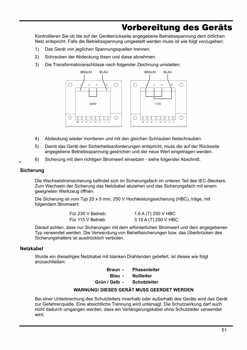
Vorbereitung des Geräts Kontrollieren Sie ob die auf der Geräterückseite angegebene Betriebsspannung dem örtlichen Netz entspricht. Falls die Betriebsspannung umgestellt werden muss ist wie folgt vorzugehen:
1) Das Gerät von jeglichen Spannungsquellen trennen.
2) Schrauben der Abdeckung lösen und diese abnehmen.
3) Die Transformatoranschlüsse nach folgender Zeichnung umstellen:
4) Abdeckung wieder montieren und mit den gleichen Schrauben festschrauben.
5) Damit das Gerät den Sicherheitsanforderungen entspricht, muss die auf der Rückseite angegebene Betriebsspannung gestrichen und der neue Wert eingetragen werden.
6) Sicherung mit dem richtigen Stromwert einsetzen - siehe folgender Abschnitt.
Sicherung
Die Wechselstromsicherung befindet sich im Sicherungsfach im unteren Teil des IEC-Steckers. Zum Wechseln der Sicherung das Netzkabel abziehen und das Sicherungsfach mit einem geeigneten Werkzeug öffnen.
Die Sicherung ist vom Typ 20 x 5 mm, 250 V Hochleistungssicherung (HBC), träge, mit folgendem Stromwert:
Für 230 V Betrieb: 1.6 A (T) 250 V HBC Für 115 V Betrieb: 3.15 A (T) 250 V HBC
Darauf achten, dass nur Sicherungen mit dem erforderlichen Stromwert und dem angegebenen Typ verwendet werden. Die Verwendung von Behelfssicherungen bzw. das Überbrücken des Sicherungshalters ist ausdrücklich verboten.
Netzkabel Wurde ein dreiadriges Netzkabel mit blanken Drahtenden geliefert, ist dieses wie folgt anzuschließen:
Braun - Phasenleiter Blau - Nullleiter
Grün / Gelb - Schutzleiter WARNUNG! DIESES GERÄT MUSS GEERDET WERDEN
Bei einer Unterbrechung des Schutzleiters innerhalb oder außerhalb des Geräts wird das Gerät zur Gefahrenquelle. Eine absichtliche Trennung wird untersagt. Die Schutzwirkung darf auch nicht dadurch umgangen werden, dass ein Verlängerungskabel ohne Schutzleiter verwendet wird.
51

Montage Dieses Gerät kann sowohl auf einem Tisch als auch in einem Einschub montiert werden und wird mit Füßen zur Tischmontage geliefert. Die vorderen Füße sind verstellbar, um einen optimalen Aufstellwinkel zu erreichen. Ein Einschubgehäuse zum Einbau der Stromversorgungen aus der QL Serie ist über den Hersteller oder Ihren Fachhändler erhältlich. Das Einschubgehäuse kann bis zu drei Geräte mit einer 1 HE oder ein Dreifachgerät und ein Einzelgerät aufnehmen. Für nicht verwendete Einschubplätze sind außerdem Abdeckblenden erhältlich.
Belüftung Das Netzgerät wird durch ein auf der Rückseite befindliches Gebläse mit mehreren Geschwindigkeiten gekühlt. Achten Sie darauf, dass weder die seitlichen Lufteinlassschlitze noch die Auslassschlitze auf der Rückseite blockiert werden. Bei Einschubmontage entweder für ausreichenden Raum um das Gerät herum sorgen, oder ein externes Gebläse zur Zwangskühlung einsetzen.
52
Anschlüsse Anschlüsse auf der Vorderseite
Die Last wird an die positive (rot) und negative (schwarz) Anschlussbuchse mit der Bezeichnung OUTPUT angeschlossen. Ein Fernfühleranschluss, soweit erforderlich, erfolgt über die Plus (+) und Minus (−) Klemmen mit der Bezeichnung REMOTE SENSE. Der Fernfühler-Betrieb wird über die Tastatur oder eine Fernsteuerungs-Schnittstelle (nur QL355P & QL564P) gewählt. Die Lampe REMOTE SENSE leuchtet auf wenn die Zuleitungskompensation gewählt ist. Nach dem Abschalten der Zuleitungs-kompensation schaltet das Gerät auf die Strom- und Spannungsüberwachung direkt an den Ausgangsbuchsen zurück.
Die mit markierte Klemme ist mit dem Gehäuse und dem Schutzleiter verbunden.
Anschlüsse auf der Rückseite Ausgänge (nur QL355P & QL564P)
Die Ausgangs- und Fernfühleranschlüsse sind auch auf der Geräterückseite vorhanden (Anschlussklemme mit den Bezeichnungen „Output +, Output −, Sense +, Sense −“). Hierbei handelt es sich um Parallelanschlüsse zu den Klemmen auf der Gerätevorderseite. Der Fernfühler-Betrieb wird über die Tastatur oder eine Fernsteuerungs-Schnittstelle gewählt. Bei Verwendung der rückseitigen Anschlüsse sollte immer auch die Zuleitungskompensation gewählt werden, damit die Stabilisierung der Ausgangsspannung im Rahmen der technischen Daten gewährleistet ist.
RS232 (nur QL355P & QL564P) 9−polige D−Buchse (kompatibel mit dem adressierbaren Modus der RS232-Schnittstelle). Anschlussbelegung:
Pin Name Beschreibung 1 − Nicht belegt 2 TXD Vom Gerät übertragene Daten 3 RXD Vom Gerät empfangene Daten 4 − Nicht belegt 5 GND Betriebserde 6 − Nicht belegt 7 RXD2 Sekundär empfangene Daten 8 TXD2 Sekundär übertragene Daten 9 GND Betriebserde
Die Stifte 2, 3 und 5 können als herkömmliche RS232-Schnittstelle mit XON/XOFF Handshaking verwendet werden. Die Stifte 7, 8 und 9 werden zusätzlich verwendet, wenn sich das Gerät im adressierbaren RS232-Modus befindet. Die Betriebserde ist mit der Geräteerde verbunden. Die RS232-Adresse wird von der Tastatur aus gesetzt.
GPIB (nur QL355P & QL564P) Die GPIB-Schnittstelle ist nicht isoliert, d. h. die GPIB-Betriebserde ist mit der Geräteerde verbunden. Folgende Befehlssätze stehen zur Verfügung:
SH1 AH1 T6 TE0 L4 LE0 SR1 RL1 PP1 DC1 DT1 C0 E2 Die GPIB-Adresse wird von der Tastatur aus gesetzt.
53
USB (nur QL355P & QL564P) Der USB-Port ist mit der Geräteerde verbunden. Es wird ein normales USB-Kabel verwendet. Durch die „Plug-and-Play“ Funktionalität unter Windows wird der Anschluss des Netzgeräts normalerweise automatisch erkannt.
Alarm-Ausgänge Der versenkt eingebaute 2-polige Anschluss mit der Bezeichnung „Alarm“ ist mit einem opto-gekoppelten NPN Schalttransistor verbunden, dessen Funktion von der Tastatur aus eingestellt werden kann (siehe Abschnitt „Alarmfunktionen“ dieser Anleitung). An die Klemmen kann eine maximale Betriebsspannung von 20 VDC angeschlossen werden. Der maximale Strom zum „Schließen“ des Schalters beträgt 1mA.
An den Klemmen keine externen Spannungen über 30 V DC anlegen.
54
Erstmalige Inbetriebnahme Dieser Abschnitt des Handbuches dient als allgemeine Einführung zu den Bedienelementen und dem Betrieb des Geräts. Vor dem erstmaligen Einsatz des Netzgeräts sollten Sie diesen Abschnitt durchlesen.
Die Tasten auf der Vorderseite, die Anschlussbuchsen und die Displayinformationen werden in diesem Handbuch in Großbuchstaben dargestellt, z. B. STORE, ESCAPE, OUTPUT, JOG. Die auf der 7-Segment Anzeige erscheinenden Informationen werden in einer anderen Schriftart und mit einer Mischung aus Groß- und Kleinbuchstaben dargestellt, z. B. StorE, GPIb, triP. Sie entsprechen somit den Zeichen die auf dem Display erscheinen.
Einschalten, Ausgang Ein/Aus Der Netzschalter befindet sich unten links auf der Gerätevorderseite.
Nach dem Einschalten nimmt das Gerät automatisch die zuletzt verwendeten Einstellungen an, allerdings ist der Ausgang zunächst immer stromlos. Der Anwender kann jedoch auch diese Standardeinstellung dahingehend verändern, dass der Ausgang den gleichen Wert wie beim letzten Abschalten des Geräts annimmt (siehe Abschnitt „Zusatzfunktionen“).
Der Gleichstromausgang wird über die Taste ON/OFF elektronisch ein- und ausgeschaltet. Bei eingeschaltetem Ausgang leuchtet diese Taste auf.
Tastatur An dieser Stelle wird lediglich auf die grundsätzliche Bedienung der Tastatur eingegangen, die Einstellung der einzelnen Parameter wird in den folgenden Abschnitten ausführlich beschrieben.
Die Bedienung des Netzgeräts wurde so konzipiert, dass der Wechsel auf eine andere Einstellung so „sicher“ wie möglich durchgeführt werden kann (d. h. die Gefahr, dass der angeschlossene Verbraucher einer zu hohen Spannung ausgesetzt wird, möglichst zu verringern) ohne die Bedienungsfreundlichkeit einzuschränken. Dies wurde erreicht indem der Benutzer bei Eingabe neuer Werte immer die Taste OK drücken muss. Durch Drücken der Taste ESCAPE kann eine Änderung jederzeit rückgängig gemacht werden. Andererseits kann der Anwender auch einfach warten bis das Gerät nach einer gewissen Zeitspanne automatisch auf die ursprüngliche Einstellung zurückkehrt .
Zusätzlich wird der Anwender durch akustische Signale, beleuchtete Tasten, LED-Anzeigen und Display-Informationen auf falsche Bedienung bzw. Eingaben aufmerksam gemacht. Ein mit dem Gerät vertrauter Anwender kann auf Wunsch auch bestimmte Warnfunktionen (z. B. Töne oder Blinkanzeigen) ausschalten - siehe Abschnitt „Zusatzfunktionen“.
Unter normalen Umständen ist die Tastatur gesperrt. Beim Drücken einer Taste ertönt ein zweifacher Warnton und weist damit auf eine unzulässige Bedienung hin. Um eine Spannung bzw. Stromstärke über die Tastatur einstellen zu können, muss zunächst die Taste V oder I (NUMERIC SET) gedrückt werden. Daraufhin erscheint auf der entsprechenden Anzeige der Wert 0,000 V oder 0,000 A (die Ziffer zur linken Seite des Dezimalkommas blinkt). Nun können Zahlenwerte zusammen mit dem Dezimalkomma eingegeben und durch Drücken der Taste OK bestätigt werden. Wurde die OK Taste nicht innerhalb von 10 Sekunden gedrückt, wird der eingegebene Wert annulliert und die Anzeige kehrt auf den vorherigen Wert zurück. Das gleiche gilt wenn die Taste ESCAPE während des Eingabevorgangs gedrückt wurde.
Die OK Taste dient hauptsächlich zur Bestätigung der Tastatureingaben. Sie hat jedoch auch eine zweite Funktion zur Anzeige von Konstantstrom/Konstantspannung (VIEW V/I LIMITS) und bewirkt dann, dass die voreingestellte Ausgangsspannung bzw. Stromstärke 3 Sekunden lang angezeigt wird. Während dieses Zeitraums erscheint der blinkende Hinweis „LIM“ im Display.
Die Taste SHIFT leuchtet beim Drücken auf und bewirkt, dass die Nummerntasten die jeweils angegebene Zweitfunktion annehmen (z. B. STORE, RECALL, etc.). Sobald eine solche Zweitfunktion gewählt worden ist, verliert die SHIFT Taste vorübergehend ihre Funktion (und ist auch nicht länger beleuchtet). Die einzelnen Tastatureingaben zur Ausführung gewählter Funktionen werden weiter unten ausführlich beschrieben. Falls innerhalb von 10 Sekunden keine
55
weitere Taste zur Ausführung einer Funktion gedrückt wurde, wird die jeweilige Funktion ungültig (gleiche Wirkung wie das Drücken der Taste ESCAPE). Die Taste SHIFT ist eine Umschalttaste, d. h. sie wird durch wiederholtes Drücken ein- und ausgeschaltet. SHIFT wird zusätzlich durch Drücken der Taste ESCAPE oder der Tasten SET V bzw. SET I annulliert.
Drehregler Mit dem Drehregler kann die Ausgangsspannung bzw. die Strombegrenzung schrittweise erhöht oder gesenkt werden. Die Schrittgröße wird mit Hilfe der Tasten JOG SET eingestellt. Diese Einstellung wirkt sich sofort auf den Ausgang aus, d. h. es ist nicht notwendig die OK Taste zu drücken. Nach dem Einschalten ist die schrittweise Einstellung zunächst immer ausgeschaltet. Um die schrittweise Einstellung der Spannung bzw. Stromstärke zu aktivieren, muss die Taste V bzw. I JOG SET gedrückt werden. Die Taste leuchtet auf. Gleichzeitig blinkt die Anzeige JOG unter der Ziffer, die zuletzt eingestellt wurde. Bei beleuchteter V bzw. I JOG SET Taste wird die JOG Anzeige beim jedem Drücken der V bzw. I Taste eine Stelle nach links verschoben. Die Wahl der Schrittgröße erfolgt nach dem Kreislaufprinzip, d. h. nach Erreichen der höchsten Schrittgröße wird beim nächsten Tastendruck wieder die kleinste Schrittgröße gewählt. Beim Einschalten ist automatisch die niederwertigste Ziffer, d. h. also die kleinste Schrittgröße gewählt. Durch Drehen des Stufenreglers im/gegen den Uhrzeigersinn wird die gewählte Ziffer erhöht/erniedrigt. Ziffern links zur eingestellten Ziffer werden automatisch erhöht/erniedrigt wenn der Zehnerbereich über- bzw. unterschritten wird. Ziffern rechts zur eingestellten Ziffer werden nicht beeinflusst, es sei denn der eingestellte Schritt über-/unterschreitet den maximalen/minimalen Wertebereich. In diesem Fall geht die Ziffer auf Null. Zum Beispiel: im 35 V Einstellbereich bei einer Schrittgröße von 1 V wechselt 33,65 V auf 34,65 V und schließlich auf 35,00 V. Bei einer Schrittgröße von 0,1 A wechselt 0,160 A auf 0,060 A und schließlich auf 0,001 A. Folgende Schrittgrößen können gewählt werden: 1 mV, 10 mV, 100 mV und 1 mA, 10 mA, 100 mA. Im Bereich 500 mA sind folgende Schrittgrößen möglich: 0,1 mA, 1 mA, 10 mA.. Der Drehregler kann durch Drücken der Taste JOG SET OFF deaktiviert werden. Durch erneutes Wählen von JOG SET V oder I kann die zuletzt verwendete Ziffernstelle wieder verändert werden. Die Schrittfunktion wird weder durch eine Zifferneingabe auf der Tastatur noch durch Betätigen der SHIFT-Funktionen beeinflusst, ist jedoch bei Wahl einer Zweitfunktion deaktiviert. Im Konstantspannungsbetrieb zeigt die rechte Anzeige den tatsächlich fließenden Strom an, d. h. nicht den Strombegrenzungswert. Wurde JOG SET I gewählt, so erscheint der Hinweis JOG unter der gewählten Ziffer (blinkt aber nur mit halber Geschwindigkeit). Um die Auswirkungen eines veränderten Strombegrenzungswerts beobachten zu können, muss der Ausgang entweder ausgeschaltet werden (so dass das Display den Strombegrenzungswert ständig anzeigt) oder es muss die Taste VIEW V/I LIMITS gedrückt werden, woraufhin der Strombegrenzungswert etwa 3 Sekunden lang angezeigt wird. Das langsame Blinken erscheint auch dann, wenn JOG SET V gewählt worden ist und die tatsächliche Spannung angezeigt wird, weil das Netzgerät den Strombegrenzungswert erreicht hat. Vom Werk aus ist das Netzgerät so konfiguriert, dass die JOG Anzeige ständig unter der gewählten Ziffer blinkt (vorausgesetzt natürlich dass die Schrittfunktion gewählt worden ist), so dass der Benutzer immer weiß welcher Parameter erhöht oder erniedrigt werden kann. Sollte dies nicht genügend Aufmerksamkeit erwecken, kann mit Hilfe der Zusatzfunktionen auch bewirkt werden, dass die ganze Ziffer blinkt. Umgekehrt lässt sich JOG Anzeige auch so einrichten, dass sie überhaupt nicht blinkt (wenn das Blinken als störend empfunden wird). Dies gilt nicht für das langsame Blinken.
56
Das Display Das Display zeigt links die Spannung (5 Ziffern) und rechts den Stromwert (4 Ziffern) an. Mit Hilfe des 7-Segment Displays können aber auch Informationen für bestimmte Funktionseinstellungen angezeigt werden (z. B. Speicherinformationen oder die Adresseneinstellung bei der Fernbedienung) indem der begrenzte „Zeichensatz“ des 7-Segment Displays voll genutzt wird. Hierbei handelt es sich notwendigerweise um eine Mischung aus Klein- und Großbuchstaben. Über und unter dem 7-Segment Display befinden sich verschiedene „verdeckte“ Anzeigen. Rechts oben über dem Display befinden sich die Anzeigen zur Darstellung des aktuell gewählten Betriebsbereichs: 35 V/3 A, 15 V/5 A oder 35 V/500 mA (QL355); 56 V/2 A, 25 V/4 A, 56 V/500 mA (QL564P). Diese Anzeigen leuchten direkt unter dem Bereich auf, der ganz oben auf dem Gerät aufgedruckt ist. Im Falle des Bereichs 500 mA wird der Hinweis „mA“ angezeigt, um darauf aufmerksam zu machen, dass gegenwärtig der Milliampere Bereich dargestellt ist. Weiterhin können folgende Anzeigen auf dem Display erscheinen: CI gibt an dass das Gerät im Konstantstrombetrieb arbeitet; LIM blinkt beim Drücken der Taste VIEW V/I LIMITS, um den aktuell gewählten Spannungs-/Strombegrenzungswert anzuzeigen; REM leuchtet auf wenn das Gerät über die Fernbedienungsschnittstelle betrieben wird (gilt nur für QL355P & QL564P). Unter den drei niederwertigsten Ziffern im Spannungs- und Stromwert-Display befinden sich die JOG Anzeigen - bei Verwendung der Schritt-Funktion blinkt die entsprechende Anzeige auf (siehe Abschnitt „Drehbarer Stufenregler“ oben).
57
Manueller Betrieb Erstbenutzer sollten zunächst das Kapitel „Erstmalige Inbetriebnahme“ lesen, um sich mit der prinzipiellen Funktionsweise von Tastatur und Drehregler vertraut zu machen.
Einstellen der Spannung Das linke Display gibt die Spannung mit einer Auflösung von 1 mV an, es sei denn das Gerät arbeitet im Konstantstrombetrieb (CI). Im CI-Betrieb wird stattdessen die tatsächliche Ausgangsspannung (die unter der eingestellten Spannung liegt) mit einer Auflösung von 10 mV angezeigt. Die letzte Ziffer (Auflösung 1 mV) ist in diesem Fall immer Null. Die Spannung kann direkt über die numerische Tastatur eingegeben werden: hierzu die Taste NUMERIC SET V drücken, den neuen Wert auf der Tastatur eingeben und mit OK bestätigen. Die allgemeine Vorgehensweise bei der Tastatureingabe ist im Abschnitt „Erstmalige Inbetriebnahme“ beschrieben und sollte zuerst durchgelesen werden. Wurde SET V gedrückt, so zeigt das Display zunächst den Wert 0,000 an. Ein neuer Spannungswert kann jetzt eingegeben und mit OK bestätigt werden (z. B. wird 12,345 V mit 1, 2, ·, 3, 4, 5 eingegeben). Die Position des Dezimalkommas ist festgelegt, um zu verhindern dass ein falscher Wert eingegeben wird. Aus diesem Grund (und um die Eingabe von führenden Nullen zu vermeiden - z. B. wird 2,345 V mit 2, ·, 3, 4, 5, OK eingegeben) werden die Ziffern links vom Dezimalkomma etwas anders dargestellt, als die Nummern rechts vom Dezimalkomma. Dies erklärt sich bei der Eingabe von selbst. Die kleinste einstellbare Spannung beträgt 0,000V, der größtmögliche Wert beträgt 35,000 V (15,000 V im Bereich 15 V/5 A). Durch Drücken der Taste OK wird die eingegebene Spannung eingestellt, wobei alle anderen Ziffern auf Null gesetzt werden. Zum Beispiel ergibt die Tastenfolge 1, 2, ·, 3, OK eine eingestellte Spannung von 12,300 V; 1, OK ergibt 1,000 V. Wird OK unmittelbar nach SET V gedrückt (im Display erscheint der Wert 0,000 V) beträgt die eingestellte Spannung 0,000 V. Durch Drücken der Taste ESCAPE (oder durch das Unterlassen weiterer Eingaben in den nächsten 10 Sekunden) kehrt das Display auf den Wert zurück, der vor Drücken der Taste SET V Gültigkeit hatte. Wird eine Spannung außerhalb des Maximalbereichs eingegeben (gilt auch bei der Eingabe von 3 Ziffern vor dem Dezimalkomma), oder wenn versucht wird mehr als 5 Ziffern einzugeben, ertönt ein zweifaches Warnsignal - die zuletzt gedrückte Taste wird ignoriert. Die Spannung kann auch mit dem Drehregler eingestellt werden. Durch Drücken der Taste JOG SET V wird die V Taste beleuchtet und die JOG Anzeige unter der zuletzt eingestellten Ziffer blinkt auf. Während die V Taste leuchtet, bewirkt jeder weitere Tastendruck ein Verschieben der JOG Anzeige eine Stelle nach links. Dies geschieht im Kreislauf, so dass nach Erreichen der höchsten Schrittgröße wieder die kleinste Schrittgröße gewählt wird. Beim Einschalten ist automatisch die niederwertigste Ziffer, d. h. also die kleinste Schrittgröße gewählt. Die wählbaren Schrittgrößen sind 1 mV, 10 mV und 100 mV. Bei aktivierter Schritteinstellung kann die Ausgangsspannung mit Hilfe des Drehreglers erhöht oder erniedrigt werden, wobei die Schrittgröße durch die Position der blinkenden JOG Anzeige angezeigt wird. Die Ausgangsspannung verändert sich sofort nach der Neueinstellung, die Taste OK muss nicht gedrückt wird. Befindet sich der Ausgang im Konstantstrombetrieb (blinkende CI Anzeige) zeigt das linke Display die tatsächliche, anstelle der eingestellten Spannung an. Wurde JOG SET V gewählt, blinkt die JOG Anzeige unter der gewählten Ziffer mit halber Geschwindigkeit. Um die Auswirkungen eines veränderten Strombegrenzungswerts beobachten zu können, muss der Ausgang entweder ausgeschaltet werden (so dass das Display den Strombegrenzungswert ständig anzeigt), oder es muss die Taste VIEW V/I LIMITS gedrückt werden, woraufhin der Strombegrenzungswert etwa 3 Sekunden lang angezeigt wird. Zu beachten ist, dass im Konstantstrombetrieb die tatsächliche Spannung gemessen und mit einer Auflösung von 10 mV angezeigt wird (die 1 mV Ziffer zeigt Null an). Weitere Einzelheiten zum Drehregler finden sich im Kapitel „Erstmalige Inbetriebnahme“.
58
Einstellen der Strombegrenzung Bei ausgeschaltetem Ausgang zeigt das rechte Display den Strombegrenzungswert mit einer Auflösung von 1 mA an (0,1 mA im Bereich 500 mA). Der Strombegrenzungswert kann direkt über die numerische Tastatur eingegeben werden: hierzu die Taste NUMERIC SET I drücken, den neuen Wert über die Tastatur eingeben und mit OK bestätigen. Die allgemeine Vorgehensweise bei der Tastatureingabe ist im Abschnitt „Erstmalige Inbetriebnahme“ beschrieben und sollte von zuerst durchgelesen werden. Wurde SET I gedrückt, so zeigt das Display zunächst den Wert 0,000 an. Ein neuer Stromwert kann jetzt eingegeben und mit OK bestätigt werden (z. B. wird 1,234 A als 1, · , 2, 3, 4 eingegeben). Die Position des Dezimalkommas ist festgelegt, um zu verhindern dass ein falscher Wert eingegeben wird. Aus diesem Grund (und um die Eingabe von führenden Nullen zu vermeiden - z. B. wird 0·234 A mit ·, 2, 3, 4, OK eingegeben) werden die Ziffern links vom Dezimalkomma etwas anders dargestellt, als die Nummern rechts vom Dezimalkomma. Dies erklärt sich bei der Eingabe von selbst. Der kleinste einstellbare Strom beträgt 0,001 A (0,1 mA im Bereich 500 mA), der größtmögliche Wert beträgt je nach gewähltem Bereich 3,000 A, 5,000 A oder 500,0 mA (QL355); 2,000 A, 4,000 A oder 500.0mA (QL564); d. h. es findet keine automatische Bereichsüberschreitung statt. Durch Drücken der Taste OK wird der jeweils eingegebene Stromwert eingestellt und alle anderen Ziffern auf Null gesetzt. Zum Beispiel ergibt die Tastenfolge 1, ·, 2, OK einen eingestellten Strom von 1,200 A; 1, OK ergibt 1,000 A. Wird OK unmittelbar nach SET V gedrückt (im Display erscheint der Wert 0,000 A) beträgt der eingestellte Strom 0,001 A. Durch Drücken der Taste ESCAPE (oder durch Unterlassen weiterer Eingaben in den nächsten 10 Sekunden) kehrt das Display auf den Wert zurück, der vor Drücken der Taste SET I Gültigkeit hatte. Wird eine Spannung außerhalb des Maximalbereichs eingegeben (gilt auch bei der Eingabe von 2 Ziffern vor dem Dezimalkomma), oder wenn versucht wird mehr als 4 Ziffern einzugeben, ertönt ein zweifaches Warnsignal - die zuletzt gedrückte Taste wird ignoriert. Der Strombegrenzungswert kann auch mit dem Drehregler eingegeben werden. Durch Drücken der Taste JOG SET I wird die I Taste beleuchtet und die JOG Anzeige unter der zuletzt eingestellten Ziffer blinkt auf. Während die I Taste leuchtet bewirkt jeder weitere Tastendruck ein Verschieben der JOG Anzeige eine Stelle nach links. Dies geschieht im Kreislauf, so dass nach Erreichen der höchsten Schrittgröße wieder die kleinste Schrittgröße gewählt wird. Beim Einschalten ist automatisch die niederwertigste Ziffer, d. h. also die kleinste Schrittgröße gewählt. Die wählbaren Schrittgrößen sind 1 mA, 10 mA und 100 mA (0,1m A, 1m A und 10 mA im Bereich 500 mA). Bei aktivierter Schritteinstellung kann der Strombegrenzungswert mit Hilfe des Drehreglers erhöht oder erniedrigt werden, wobei die Schrittgröße durch die Position der blinkenden JOG Anzeige angegeben wird. Der Ausgangsstrom verändert sich sofort nach der Neueinstellung, die Taste OK muss nicht gedrückt werden. Bei eingeschaltetem Ausgang zeigt das rechte Display den tatsächlichen Stromwert und nicht den Strombegrenzungswert an (außer im Konstantstrombetrieb). Wurde JOG SET I gewählt blinkt die JOG Anzeige unter der gewählten Ziffer mit halber Geschwindigkeit. Um die Auswirkungen eines veränderten Strombegrenzungswerts beobachten zu können, muss der Ausgang entweder ausgeschaltet werden (so dass das Display den Strombegrenzungswert ständig anzeigt) oder es muss die Taste VIEW V/I LIMITS gedrückt werden, woraufhin der Strombegrenzungswert etwa 3 Sekunden lang angezeigt wird.
Momentanstrom Mit Hilfe der Strombegrenzungsfunktion kann der Dauerausgangsstrom bis auf 1 mA herab begrenzt werden (0,1 mA im 500 mA Bereich). Wie bei allen Präsizionsnetzgeräten wird jedoch auch hier der Ausgang mit einem Kondensator überbrückt, um eine stabile Ausgangsspannung und ein gutes dynamisches Verhalten zu gewährleisten. Dieser Kondensator lädt sich bis zur Höhe der Ausgangsspannung auf und erzeugt beim Kurzschließen des Ausgangs durch seine Entladung einen Stromimpuls, auf den die Strombegrenzung keinen Einfluss hat.
59
Bereichswahl Das Netzgerät verfügt über drei Bereiche: 35 V/3 A, 15 V/5 A und 35 V/500 mA (QL355); 56 V/ 2A, 25 V/4 A und 56 V/500 mA (QL564). Der gewählte Bereich wird durch eine beleuchtete Anzeige unter der entsprechenden Beschriftung oben rechts auf dem Gerät angezeigt. Im Bereich 500 mA erscheint die Anzeige „mA“, um darauf hinzuweisen dass der Strommesser Milliampere anstelle von Ampere angibt. Um den Bereich zu wechseln, die Taste SHIFT gefolgt von RANGE bzw. RANGE drücken. Jeder Tastendruck auf RANGE wählt den nächsten Bereich links, während jeder Druck auf die Taste RANGE den nächsten Bereich rechts anwählt (kein Kreislaufeffekt). Beim Wechseln des Bereichs blinkt die Anzeige des jeweiligen Bereichs zusammen mit der OK Taste. Durch Drücken auf OK wird der neue Bereich bestätigt. Sie können den Bereichswechsel annullieren indem Sie auf ESCAPE drücken. Wird während des Bereichswechsels eine andere Taste gedrückt ertönt ein zweifacher Warnton, ansonsten hat das Drücken einer falschen Taste keine Folgen. Falls die Taste OK nicht innerhalb von 10 Sekunden gedrückt wurde, bleibt der Bereich in der vorherigen Einstellung.
Der Bereich kann nur bei ausgeschaltetem Ausgang gewechselt werden. Werden die Tasten RANGE bzw. RANGE bei eingeschaltetem Ausgang gedrückt blinken die Tasten ON/OFF
und OK. Daraufhin kann entweder der Ausgang mit der Taste ON/OFF ausgeschaltet werden um dann nach Drücken auf OK auf einen anderen Bereich zu wechseln, oder Sie können direkt auf OK drücken. In diesem Fall wird der Ausgang automatisch abgeschaltet, so dass eine andere Bereichswahl möglich ist.
Wird der jeweils eingestellte Strom- oder Spannungsgrenzwert durch einen neu gewählten Bereich überschritten, so ist die Bereichswahl zwar gültig, doch wird die Einstellung auf den Maximalwert des neu gewählten Bereichs begrenzt.
Zu beachten ist, dass der eingestellte Überspannungsschutz (OVP) beim Bereichswechsel nicht verändert wird (so bleibt z. B. eine OVP-Einstellung von 38 V auch im 15 V Bereich gültig). Der Benutzer muss also die Überspannungseinstellung selbst vornehmen.
Anschluss der Last Die Last wird an die Plus- (rot) und Minus- (schwarz) Klemmen mit der Bezeichnung OUTPUT angeschlossen. Beide Klemmen sind galvanisch getrennt und können daher an Erde gelegt werden.
Fernfühler Obwohl das Gerät eine sehr geringe Ausgangsimpedanz besitzt, erhöht sich diese zwangsweise durch den Widerstand der angeschlossen Kabel. Bei hohen Strömen ergibt sich hieraus ein deutlicher Unterschied zwischen der angezeigten Quellspannung und der tatsächlichen Lastspannung (zwei Anschlusskabel mit 20 mΩ erzeugen z. B. bei einem Strom von 5 A einen Spannungsabfall von 0,2 V). Dieses Problem lässt sich zwar durch Verwendung kurzer Anschlusskabel mit großem Querschnitt zwar einschränken, aber besser ist es diesen Effekt mit Hilfe der Fernfühlerfunktion ganz zu umgehen.
Dazu müssen die Fernfühlerklemmen (Sense) an der Last anstelle der Spannungsquelle angeschlossen werden. Schließen Sie die Kabel an die Federklemmen des REMOTE SENSE Anschlusses und direkt an der Last an.
Wählen Sie die Fernfühlerfunktion durch Drücken der Tasten SHIFT, SENSE. Die Taste OK blinkt, die Lampe über den Fernfühleranschlüssen leuchtet auf und zeigt damit an, dass diese Funktion nach Drücken auf OK aktiviert wird. Mit OK bestätigen oder mit ESCAPE annullieren. Die Fernfühlerfunktion wird durch erneutes Drücken auf SHIFT, SENSE wieder abgeschaltet (OK blinkt, die Fernfühlerleuchte geht aus und zeigt damit an, dass die Fernfühlerfunktion nach Drücken auf OK abgeschaltet wird. Mit OK bestätigen oder mit ESCAPE annullieren.
Um Instabilität und dynamisches Fehlverhalten zu vermeiden muss darauf geachtet werden, dass eine gute Verbindung zwischen jedem Ausgangs- und Fernfühlerkabel besteht. Dies wird erreicht indem man entweder die Kabel miteinander verdrillt oder ein abgeschirmtes Koaxialkabel
60
verwendet (die Fernfühlerleitung bildet hierbei den Innenleiter). Auch ein Elektrolytkondensator der direkt den Lastanschluss überbrückt kann hilfreich sein. Der Spannungsabfall des jeweiligen Ausgangskabels darf 0,5 Volt nicht überschreiten. Das Modell QL355P & QL564P verfügt über Ausgangs- und Sense-Klemmen auf der Rückseite (nützlich beim Regaleinbau). Die Sense-Klemmen auf der Rückseite sind immer in Verbindung mit den Ausgangsklemmen auf der Rückseite zu verwenden.
Falscher Anschluss im Sense-Betrieb Der Ausgang schaltet sich automatisch ab wenn die Spannungsdifferenz zwischen einem Ausgang und dem zugehörigen Sense-Anschluss ca. 1 V überschreitet. Dies ist dann der Fall wenn die Fernfühlerkabel falsch an der Last angeschlossen sind oder wenn versucht wird einen Strom über die Sense-Kabel zu entnehmen. In einem solchen Fall erscheint die Meldung SENSE triP auf dem Display und der Ausgang wird abgeschaltet. Wird nun ESCAPE gedrückt, zeigt das Display die voreingestellte Spannung und den Stromgrenzwert an. Nach Beseitigung der Fehlerquelle kann der Ausgang wieder eingeschaltet werden.
Serielle oder Parallelschaltung mit anderen Spannungsquellen Der Ausgang des Netzgeräts ist galvanisch getrennt und kann mit anderen Netzgeräten in Reihe geschaltet werden, um hohe Gleichstromspannungen bis zu 300 V DC zu erzeugen.
Die maximal zulässige Spannung zwischen einer Anschlussklemme und Erde ( ) beträgt 300 V DC.
WARNUNG! Spannungen dieser Größenordnung sind äußerst gefährlich. Daher müssen die Ausgangsklemmen bei Verwendung derartiger Spannung unbedingt vor Berührung geschützt werden. Auf keinen Fall dürfen die Ausgangsklemmen in einem solchen Fall berührt werden. Sämtliche Anschlüsse an den Klemmen dürfen erst dann erfolgen, wenn alle betreffenden Netzgeräte ausgeschaltet sind.
Zu beachten ist, dass das Gerät nur als Stromquelle dient und keine Ströme ableiten kann, d. h. es können keine gegenphasigen Geräte angeschlossen werden.
Das Gerät kann auch mit anderen Netzteilen parallel geschaltet werden um eine höhere Stromabgabe zu erzielen. Werden mehrere Geräte parallel geschaltet, entspricht die Ausgangsspannung dem Gerät mit der höchsten Ausgangsspannung. Dies gilt nur solange der Strombegrenzungswert des betreffenden Geräts nicht erreicht wird. Ist dies der Fall fällt die Ausgangsspannung auf die nächsthöchste Einstellung ab usw. Bei Konstantstrombetrieb können mehrere Geräte parallel geschaltet werden um einen Strom mit der Summe der jeweiligen Stromgrenzwerte bereit zu stellen.
Beachten Sie ,dass die Ausgangsklemmen für einen maximalen Strom von 15 A ausgelegt sind. Sollen mehrere Quellen parallel geschalten werden um einen höheren Strom zu erreichen muss die Verbindung an einer anderen Stelle erfolgen und nicht an einer der Anschlussklemmen.
Überspannungsschutz Der Überspannungsschutz (OVP) kann zwischen 1,0 V und 40 V (QL355), 1,0 und 62 V (QL564) eingestellt werden. Übersteigt die Ausgangsspannung den eingestellten OVP-Wert schaltet sich der Ausgang sofort ab (generell innerhalb von 100 µs) und verhindert somit eine Beschädigung der angeschlossen Testschaltung. Der Überspannungsschutz gilt für den Fall dass unbeabsichtigt eine zu hohe Spannung am Gerät oder über die Fernbedienung eingestellt wird, aber auch wenn eine zu hohe Fremdspannung an den Ausgangsklemmen anliegt oder die Steuerschaltung im Gerät selbst versagt.
Der Überspannungsschutz wird durch Drücken auf SHIFT, OVP eingestellt. Die Anzeige für die Schrittgröße 100 mV leuchtet auf und die JOG Anzeige blinkt. Nun kann der OVP-Wert mit dem Drehregler in 100 mV Schritten erhöht bzw. erniedrigt werden. Durch Drücken auf OK wird die neue Einstellung bestätigt. Mit der Taste ESCAPE kann die Einstellung rückgängig gemacht werden. Der werksseitig voreingestellte Wert ist 40,0 V (QL355), 62,0 V (QL564).
61
Wurde der Überspannungsschutz ausgelöst, erscheint die Meldung OUP triP auf dem Display und der Ausgang wird abgeschaltet. Durch Drücken auf ESCAPE wird die Meldung ausgeblendet, das Display zeigt nun die Einstellwerte für Spannungs- und Strombegrenzung an. Nachdem die Ursache für den Auslöser behoben ist (oder der Grenzwert verändert wurde) kann der Ausgang wieder eingeschaltet werden.
Beachten Sie bitte dass sich der OVP-Wert bei einer Bereichsumstellung nicht ändert (so bleibt z. B. eine OVP-Einstellung von 38 V auch im 15 V Bereich gültig). Es ist daher Aufgabe des Benutzers die OVP-Einstellung ggf. neu anzupassen.
Zu beachten ist auch, dass es möglich ist, einen Überspannungswert einzugeben der unter der eingestellten Ausgangsspannung liegt. Befindet sich das Gerät im Konstantstrombetrieb liegt die Ausgangsspannung ohnehin unter der eingestellten Spannung. In diesem Fall kann der OVP-Wert so gesetzt werden, dass er über der tatsächlichen, jedoch unter der eingestellten Ausgangsspannung liegt. Auf diese Weise schaltet sich der Ausgang automatisch ab wenn ein Fehler vorliegt bei dem die Lastimpedanz steigt und damit auch die tatsächliche Ausgangsspannung den OVP-Wert überschreitet.
Überstromschutz Der Überstromschutz (OCP) kann zwischen 0,01 A und 5,5 A (QL355), 0,01 A und 4,4 A (QL564) eingestellt werden. Übersteigt der Ausgangsstrom den eingestellten OCP-Wert schaltet sich der Ausgang ab (generell innerhalb von 35 ms).
Der Überstromschutz wird durch Drücken auf SHIFT, OCP eingestellt. Die Anzeige für die Schrittgröße 10 mA (JOG) blinkt. Nun kann der OCP-Wert mit dem Drehregler in 10 mA Schritten erhöht bzw. erniedrigt werden. Durch Drücken auf OK wird die neue Einstellung bestätigt. Mit der Taste ESCAPE kann die Einstellung rückgängig gemacht werden. Der werksseitig voreingestellte Wert ist 5,50 A.
Wurde der Überstromschutz ausgelöst, erscheint die Meldung OCP triP auf dem Display und der Ausgang wird abgeschaltet. Durch Drücken auf ESCAPE wird die Meldung ausgeblendet, das Display zeigt nun die Einstellwerte für Spannungs- und Strombegrenzung an. Nachdem die Ursache für den Auslöser behoben ist (oder der Grenzwert verändert wurde) kann der Ausgang wieder eingeschaltet werden.
Beachten Sie bitte, dass sich der OCP-Wert (wie beim Überspannungsschutz) bei einer Bereichsumstellung nicht ändert.
Zu beachten ist auch, dass es möglich ist einen Überstromwert einzugeben, der unter dem eingestellten Strombegrenzungswert liegt. So kann das Netzgerät z. B. dazu verwendet werden ein Testgerät mit einer Spitzenstromaufnahme von z. B. 2 Ampere wiederholt zu prüfen. Ein fehlerhaftes Testgerät würde jedoch einen Strom von mehr als 2 Ampere aufnehmen und durch die 2 A Strombegrenzung nicht vor Beschädigung geschützt werden. In diesem Fall könnte die Strombegrenzung auf 2,1 A und der OCP-Wert auf 2,0 A eingestellt werden, um sicherzustellen dass ein fehlerhaftes Testgerät zur Abschaltung der Spannungsversorgung führt.
Schutz des Ausgangs Neben OVP und OCP zum Überspannungs- bzw. Überstromschutz ist der Ausgang zusätzlich durch eine Diode gegen eine Rückspannung geschützt. Diese Rückspannung darf 3 Ampere nicht überschreiten (Spannungsspitzen können erheblich höher liegen).
Ausgangsleistung (V x A) Nach Drücken auf SHIFT, V x A zeigt das Spannungs-Display das Produkt aus gemessener Ausgangsspannung und gemessenem Strom an. Im Display erscheint UA. Der angezeigte Wert V x A stellt eine Momentaufnahme dar, d. h. es wird die momentan gemessene Ausgangleistung und nicht die Dauer-Nennleistung angezeigt. Der angezeigte Wert bleibt erhalten, solange die Taste gedrückt ist. Durch Drücken auf V x A wird die Umschaltfunktion (SHIFT) annulliert. Während V x A angezeigt ist, wird die Schrittfunktion wird vorübergehend deaktiviert (die JOG Anzeigen sind ausgeschaltet).
62
Temperaturschutz Bei Überschreiten der internen Temperaturgrenze (z. B. weil die Lüfter blockiert sind) schaltet sich der Ausgang aus und das Display zeigt die Meldung OTP triP. Wird nun ESCAPE gedrückt sind zwei Vorgänge möglich:
i. Falls keine Übertemperatur mehr gegeben ist, wird die Meldung gelöscht. Das Display zeigt wieder die eingestellte Spannung und den Strombegrenzungswert an. Vorausgesetzt die Ursache für das Auftreten der Übertemperatur wurde behoben kann der Ausgang wieder eingeschaltet werden.
ii. Liegt die Temperatur des Geräts weiterhin über dem Grenzwert, blinkt die OTP triP Meldung langsam bis sich das Gerät abgekühlt hat. Danach zeigt das Display wieder die eingestellte Spannung und den Strombegrenzungswert an. Vorausgesetzt die Ursache für das Auftreten der Übertemperatur wurde behoben kann der Ausgang wieder eingeschaltet werden.
Alarmausgang Der versenkt montierte 2-polige Anschluss auf der Geräterückseite ist direkt mit einem optogekoppelten NPN-Schalttransistor verbunden (Pin 1 Emitter, Pin 2 Kollektor) der entsprechend den Bedingungen im Abschnitt „Zusatzfunktionen“ (siehe weiter unten) schaltet. Die Standardeinstellung ist ein Schließen des Schalters unter jeglichen Auslösebedingungen (OVP, OCP, SENSE oder OTP). Die maximale Leerlaufspannung für diesen Schalter beträgt 30 VDC, der Nennstrom zum Schließen des Schalters ist 1 mA.
Einstellungen speichern Das Gerät kann bis zu 10 verschiedene Einstellungen in einem nicht flüchtigen Speicher halten. Bei den gespeicherten Parametern handelt es sich um: Bereich, Spannung, Strombegrenzungs-wert, OVP und OCP. Der Ausgangsstatus und die Einstellungen für den Fernfühler werden nicht gespeichert.
Um eine Einstellung zu speichern werden die Tasten SHIFT, STORE, Speicher-Nr., und OK gedrückt. Die Speichernummer kann die Werte 0 bis 9 annehmen.
Nach Drücken von SHIFT, STORE erscheint die Meldung StorE - auf dem Display. Die Umschaltfunktion (SHIFT) wird deaktiviert (die Lampe erlischt). Wird nun eine Zifferntaste gedrückt erscheint, die jeweilige Nummer anstelle von – im Display mit der Kennzeichnung E (Speicher leer) oder F (Speicher voll) daneben - z. B. StorE 1.E, StorE 2.F . Alle Speicher können durch Drücken einer Ziffer nach der anderen kontrolliert werden (ohne dass jedes Mal SHIFT, STORE gedrückt werden muss) bevor die gewählte Speichernummer schließlich mit OK bestätigt wird. Ein belegter Speicher kann mit neuen Einstellungen überschrieben werden. Durch Drücken auf ESCAPE (oder 10 Sekunden Wartezeit) kann die Speicherfunktion jederzeit deaktiviert werden, vorausgesetzt die OK Taste wurde noch nicht betätigt.
Speichereinstellungen löschen Jeder beliebige Speicher kann wie folgt gelöscht werden: den gewünschten Speicher durch Drücken von SHIFT, STORE, Speicher-Nr. wählen. Dann die Taste · drücken. Im Display erscheint die Meldung dELEt anstelle von StorE , z. B. dELEt 2.F . Durch Drücken auf OK wird der Inhalt des betreffenden Speichers gelöscht.
Einstellungen aufrufen Um eine bestimmte Speichereinstellung aufzurufen wird die Tastenfolge SHIFT, RECALL, Speicher-Nr., OK gedrückt. Die Speichernummer ist eine Zahl von 0 bis 9. Nach Drücken von SHIFT, RECALL erscheint rECAL – im Display. Die Umschaltfunktion wird deaktiviert (die Lampe erlischt). Wird nun eine Zifferntaste zwischen 0 und 9 gedrückt, erscheinen die jeweiligen Spannungs- und Stromeinstellungen im Display. Das Display blinkt um darauf aufmerksam zu machen, dass eine Einstellung aufgerufen wurde.
63
Durch Drücken einer Ziffer nach der anderen können beliebige Speichernummern aufgerufen werden (ohne dass jedes Mal SHIFT, RECALL gedrückt werden muss) bevor die gewählte Speichernummer schließlich mit OK bestätigt wird. Ein leerer Speicher wird durch ein blinkendes – Symbol für jede Displaystelle angezeigt. Durch Drücken auf ESCAPE (oder 10 Sekunden Wartezeit) kann die Speicherfunktion jederzeit deaktiviert werden, vorausgesetzt die OK Taste wurde noch nicht betätigt. Einstellungen können unabhängig davon ausgerufen werden, ob der Ausgang ein- oder ausgeschaltet ist. Tritt bei der aufgerufenen Speichereinstellung jedoch ein Bereichswechsel auf wird der Ausgang abgeschaltet, um etwaige „Pannen“ zu vermeiden. Nach Drücken von SHIFT, RECALL, Speicher-Nr. blinkt die ON/OFF Taste (in Verbindung mit der OK Taste) wenn die Wahl des aufgerufenen Speichers einen Bereichswechsel nach sich ziehen würde. Der Ausgang kann mit der ON/OFF Taste ausgeschaltet werden, um die aufgerufene Speichereinstellung dann mit OK zu aktivieren. Es ist auch möglich OK direkt zu drücken, um den Ausgang automatisch abzuschalten und die aufgerufene Einstellung auf diese Weise zu aktivieren.
Zusatzfunktionen Die vom Werk aus eingestellten Funktionen können mit Hilfe der Taste # (Zusatzfunktionen) vom Benutzer verändert werden. Alle Funktionsänderungen (siehe folgende Tabelle) wird durch Drücken der Tastenfolge SHIFT, #, nn eingeleitet, wobei sich „nn“ auf die 2-stellige Nummer in der Tabelle bezieht. Nach Eingabe der 2-stelligen Nummer geht die Beleuchtung der SHIFT Taste aus und es ertönt ein akustisches Signal um den Vorgang zu bestätigen.
# Code Funktion 00 Ausgang beim Einschalten immer aus (Werkseinstellung)
01 Ausgangsstatus beim Einschalten der gleiche wie beim letzten Ausschalten
20 Alarmausgang bei ausgeschaltetem Ausgang 'offen‘, bei eingeschaltetem Ausgang 'geschlossen'
21 (wird bei Netzgeräten mit nur einem Ausgang nicht verwendet)
22 Alarmausgang 'geschlossen' bei Auslösen des Übertemperaturschutzes
23 Alarmausgang 'geschlossen' bei Auslösen des im Sense-Betrieb
24 Alarmausgang 'geschlossen' bei Auslösen des Überstromschutzes
25 Alarmausgang 'geschlossen' bei Auslösen des Überspannungsschutzes
26 Alarmausgang 'geschlossen' bei allen Auslösern (Standardeinstellung)
30 Akustisches Signal aus
31 Akustisches Signal ein (Standardeinstellung). Ein einzelner Ton dient zur Bestätigung, ein doppelter Ton weist auf eine falsche Eingabe hin.
40 JOG Anzeige blinkt, JOG Anzeige blinkt nur bei wenn JOG „verdeckt“ ist
41 JOG Anzeige blinkt immer, außer wenn „verdeckt“ (Werkseinstellung)
42 JOG Anzeige blinkt nicht, außer wenn „verdeckt“ (langsames Blinken)
91 Lädt die Standard-Kalibrierparameter. Siehe Wartungshandbuch
92 Zeigt die Firmware-Version im Display an
93 Stellt diese Zusatzfunktionen (#) auf Werkseinstellung zurück
99 Kalibriermodus. Siehe Wartungsanleitung.
64
Standardeinstellungen Vom Werk aus wurden folgende Standardeinstellungen gesetzt, die beim ersten Einschalten des Geräts gültig sind:
Bereich: 35 V/3 A (QL355); 56 V/2 A (QL564)
Spannung: 1,000V
Strombegrenzung: 1,000A
OVP: 40 V (QL355); 62 V (QL564)
OCP: 5·5 A (QL355); 4,4 A (QL564)
Ausgang: Ausgang aus; Fernfühler aus
# Einstellungen: 00 Ausgang beim Einschalten immer aus
26 Alarmausgang beim Auslösen 'geschlossen ‘
31 akustisches Signal ein
41 JOG Anzeige blinkt immer; langsames Blinken wenn „verdeckt“
RS232: 9600 Baud (nur QL355P & QL564P)
Adresse: 11 (nur QL355P & QL564P)
Fehlermeldungen Die folgenden Hardware-Fehler werden mit der entsprechenden Nummer im Display angezeigt. Die Taste OK blinkt. Wird sie gedrückt so wird der Fehler ignoriert und der Betrieb wird wie beschrieben fortgesetzt.
Fehler Nr. Fehlerbeschreibung Wirkung bei Drücken auf OK 1 Kalibrierkonstanten wurden beim
Einschalten korruptiert Standard Kalibrierparameter werden geladen
2 Extrafunktionen (#) wurden beim Einschalten korruptiert
Lädt Standard #-Einstellungen
3 Abschalteinstellungen wurden beim Einschalten nicht korrekt geladen
Lädt Standard-Einschalteinstellungen
Wird das Gerät ausgeschaltet während eine Fehlermeldung angezeigt ist bleiben alle Einstellungen unverändert.
Wartung Der Hersteller bzw. seine Auslandsvertretungen stellen einen Reparaturdienst für Geräte bereit, bei denen Störungen auftreten. Falls die Besitzer ihre eigene Wartungsarbeiten durchführen wollen, sollten diese nur von gelernten Fachkräften und in Verbindung mit der Wartungsanleitung vorgenommen werden, letztere kann direkt vom Hersteller oder über seine Auslandsvertretungen bezogen werden kann..
Reinigung Falls das Gerät gereinigt werden muss, einen leicht mit Wasser oder einem milden Reinigungsmittel angefeuchteten Lappen verwenden.
WARNUNG! ZUR VERMEIDUNG VON ELEKTRISCHEM SCHLAG BZW. SCHÄDEN AM GERÄT, STETS DARAUF ACHTEN, DASS KEIN WASSER IN DAS GERÄTEINNERE GELANGT. ZUR VERMEIDUNG VON SCHÄDEN AM GEHÄUSE, KEINE LÖSUNGSMITTEL ZUR GEHÄUSEREINIGUNG VERWENDEN!
65
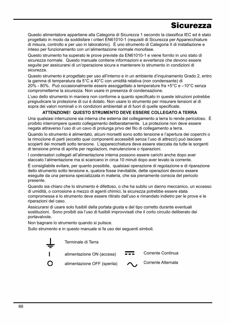
Sicurezza
Questo alimentatore appartiene alla Categoria di Sicurezza 1 secondo la classifica IEC ed è stato progettato in modo da soddisfare i criteri EN61010-1 (requisiti di Sicurezza per Apparecchiature di misura, controllo e per uso in laboratorio). È uno strumento di Categoria II di installazione e inteso per funzionamento con un’alimentazione normale monofase. Questo strumento ha superato le prove previste da EN61010-1 e viene fornito in uno stato di sicurezza normale. Questo manuale contiene informazioni e avvertenze che devono essere seguite per assicurarsi di un’operazione sicura e mantenere lo strumento in condizioni di sicurezza. Questo strumento è progettato per uso all’interno e in un ambiente d’inquinamento Grado 2, entro la gamma di temperatura da 5°C a 40°C con umidità relativa (non condensante) di 20% - 80%. Può occasionalmente essere assoggettato a temperature fra +5°C e –10°C senza comprometterne la sicurezza. Non usare in presenza di condensazione. L’uso dello strumento in maniera non conforme a quanto specificato in queste istruzioni potrebbe pregiudicare la protezione di cui è dotato. Non usare lo strumento per misurare tensioni al di sopra dei valori nominali o in condizioni ambientali al di fuori di quelle specificate.
ATTENZIONE! QUESTO STRUMENTO DEVE ESSERE COLLEGATO A TERRA Una qualsiasi interruzione sia interna che esterna del collegamento a terra lo rende pericoloso. È proibito interrompere questo collegamento deliberatamente. La protezione non deve essere negata attraverso l’uso di un cavo di prolunga privo del filo di collegamento a terra. Quando lo strumento è alimentato, alcuni morsetti sono sotto tensione e l’apertura dei coperchi o la rimozione di parti (eccetto quei componenti accessibili senza l’uso di attrezzi) può lasciare scoperti dei morsetti sotto tensione. L’apparecchiatura deve essere staccata da tutte le sorgenti di tensione prima di aprirla per regolazioni, manutenzione o riparazioni. I condensatori collegati all’alimentazione interna possono essere carichi anche dopo aver staccato l’alimentazione ma si scaricano in circa 10 minuti dopo aver levato la corrente. È consigliabile evitare, per quanto possibile, qualsiasi operazione di regolazione e di riparazione dello strumento sotto tensione e, qualora fosse inevitabile, dette operazioni devono essere eseguite da una persona specializzata in materia, che sia pienamente conscia del pericolo presente. Quando sia chiaro che lo strumento è difettoso, o che ha subito un danno meccanico, un eccesso di umidità, o corrosione a mezzo di agenti chimici, la sicurezza potrebbe essere stata compromessa e lo strumento deve essere ritirato dall’uso e rimandato indietro per le prove e le riparazioni del caso. Assicurarsi di usare solo fusibili della portata giusta e del tipo corretto durante eventuali sostituzioni. Sono proibiti sia l’uso di fusibili improvvisati che il corto circuito deliberato dei portavalvole. Non bagnare lo strumento quando si pulisce. Sullo strumento e in questo manuale si fa uso dei seguenti simboli.
Terminale di Terra
l alimentazione ON (accesa) Corrente Continua
alimentazione OFF (spenta)
Corrente Alternata
66
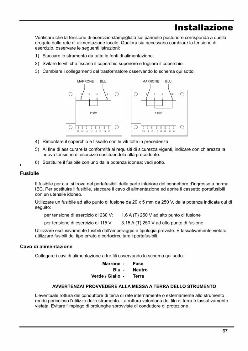
Installazione Verificare che la tensione di esercizio stampigliata sul pannello posteriore corrisponda a quella erogata dalla rete di alimentazione locale. Qualora sia necessario cambiare la tensione di esercizio, osservare le seguenti istruzioni:
1) Staccare lo strumento da tutte le fonti di alimentazione.
2) Svitare le viti che fissano il coperchio superiore e togliere il coperchio.
3) Cambiare i collegamenti del trasformatore osservando lo schema qui sotto:
4) Rimontare il coperchio e fissarlo con le viti tolte in precedenza.
5) Al fine di assicurare la conformità ai requisiti di sicurezza vigenti, indicare con chiarezza la nuova tensione di esercizio sostituendola alla precedente.
6) Sostituire il fusibile con uno dalla potenza idonea; vedi sotto.
Fusibile
Il fusibile per c.a. si trova nel portafusibili della parte inferiore del connettore d'ingresso a norma IEC. Per sostituire il fusibile, staccare il cavo di alimentazione ed aprire il cassetto portafusibili con un utensile idoneo.
Utilizzare un fusibile ad alto punto di fusione da 20 x 5 mm da 250 V, dalla potenza indicata qui di seguito:
per tensione di esercizio di 230 V: 1.6 A (T) 250 V ad alto punto di fusione
per tensione di esercizio di 115 V: 3.15 A (T) 250 V ad alto punto di fusione
Utilizzare esclusivamente fusibili dall'amperaggio e tipologia previste. È tassativamente vietato utilizzare fusibili del tipo errato e cortocircuitare i portafusibili.
Cavo di alimentazione
Collegare i cavi di alimentazione a tre fili osservando lo schema qui sotto:
Marrone - Fase Blu - Neutro
Verde / Giallo - Terra
AVVERTENZA! PROVVEDERE ALLA MESSA A TERRA DELLO STRUMENTO
L'eventuale rottura del conduttore di terra di rete internamente o esternamente allo strumento rende pericoloso l'utilizzo dello strumento. La rottura volontaria del filo di terra è tassativamente vietata. Evitare l'impiego di prolunghe sprovviste di conduttore di protezione.
67
Montaggio Lo strumento può essere montato su banco o su rack. Viene fornito provvisto di piedini destinati al montaggio su banco. I piedini anteriori sono dotati di un meccanismo che consente di orientare a piacimento il pannello. Il rack destinato al montaggio degli alimentatori della serie QL può essere acquistato direttamente dal Costruttore o dal rivenditore di fiducia. Il rack è un grado di ospitare 1, 2 o 3 alimentatori singoli od un alimentatore triplo e uno singolo; è anche possibile acquistare supporti di chiusura per le posizioni del rack non utilizzate.
Ventilazione Il raffreddamento dell'alimentatore viene effettuato dalla sofisticata ventola plurivelocità, che convoglia l'aria verso il retro dell'apparecchio. Evitare di ostruire le feritoie d'ingresso dell'aria sui pannelli laterali e posteriori. Nel caso di montaggio su rack, prevedere uno spazio libero sufficiente intorno allo strumento e/o utilizzare un ripiano di ventilazione per il raffreddamento forzato.
68
Collegamenti Collegamenti al pannello frontale
Collegare il carico ai morsetti positivo (rosso) e negativo (nero) contrassegnati OUTPUT. Gli eventuali collegamenti al carico dei rilevatori remoti si effettuano dai morsetti contrassegnati REMOTE SENSE (RILEVATORE REMOTO) positivo (+) e negativo (−). L'inserimento dei rilevatori remoti si effettua dalla tastiera o dall'interfaccia di controllo remota (solo per il QL355P & QL564P); quando si inserisce questa modalità di funzionamento, si accende la spia REMOTE SENSE. La disattivazione della modalità REMOTE SENSE riporta lo strumento alla modalità rilevamento locale sui morsetti di uscita.
Il morsetto contrassegnato dal simbolo va collegato al telaio e alla messa a terra.
Collegamenti al pannello posteriore Morsetti di uscita (solo per il QL355P & QL564P)
I morsetti di uscita e di rilevamento sono duplicati sulla morsettiera avvitabile del pannello posteriore e sono contrassegnati dalle diciture Output +, Output −, Sense + e Sense − ; questi collegamenti sono montati parallelamente a quelli sul pannello anteriore. La selezione della modalità Remote sense viene effettuata tramite la tastiera o l'interfaccia di controllo remota. Quando si utilizzano i morsetti sul pannello posteriore, occorre selezionare sempre la modalità remote sense per mantenere sempre i valori previsti di erogazione di corrente.
RS232 (solo per il QL355P &QL564P) Connettore a vaschetta a 9 pin compatibile con la porta RS232 indirizzabile. I collegamenti dei pin sono indicati qui di seguito:
Pin Denom. Descrizione 1 − Nessun collegamento interno 2 TXD Dati trasmessi dallo strumento 3 RXD Dati ricevuti dallo strumento 4 − Nessun collegamento interno 5 GND Terra segnale 6 − Nessun collegamento interno 7 RXD2 Dati secondari ricevuti 8 TXD2 Dati secondari trasmessi 9 GND Terra segnale
I pin 2, 3 e 5 possono essere utilizzati come una tradizionale porta RS232 con handshaking XON/XOFF. I pin 7, 8 e 9 vengono utilizzati quando lo strumento funziona nella modalità RS232 indirizzabile. Le messe a terra dei segnali sono collegate alla messa a terra dello strumento. L'indirizzo RS232 viene impostato dalla tastiera.
GPIB (solo per il QL355P & QL564P) L'interfaccia GPIB non è isolata; le messe a terra del segnale GPIB sono collegate alla messa a terra dello strumento.
I subset adottati sono indicati qui di seguito:
SH1 AH1 T6 TE0 L4 LE0 SR1 RL1 PP1 DC1 DT1 C0 E2
L'indirizzo GPIB viene impostato dalla tastiera.
69
USB (solo per il QL355P & QL564P) La porta USB viene collegata alla messa a terra dello strumento ed ospita un cavo USB standard. Le funzioni plug-and-play di Windows dovrebbero riconoscere automaticamente che lo strumento è stato collegato.
Uscite degli allarmi Il connettore a 2 pin incassato contrassegnato dalla dicitura Alarm (Allarme) consente di accedere al transistor di commutazione NPN optoisolato, la cui funzione può essere impostata dalla tastiera; vedi la sezione Allarmi nel presente manuale.
La tensione massima di esercizio che può essere erogata a tutti i morsetti è 20 V c.c. e il calo massimo di corrente per la chiusura dell'interruttore è 1 mA.
Verificare che le eventuali tensioni esterne erogate ai morsetti non superino i 30 V c.c.
Primo utilizzo La presente sezione riporta la descrizione generale dei comandi e del funzionamento dello strumento e deve essere letta attentamente prima di utilizzare l'alimentatore per la prima volta. Nel presente manuale i tasti, i collegamenti e i segnalatori del display sul pannello anteriore sono indicati in lettere maiuscole, ad es. STORE, ESCAPE, OUTPUT, JOG. I messaggi visualizzati sul display a 7 caratteri sono stampati in caratteri di stampa diversi, ad es. StorE, GPIb, triP in maiuscolo o in minuscolo per rappresentare i caratteri visualizzati sul display a 7 caratteri dello strumento.
Pulsante di accensione, pulsante erogazione On/Off L'interruttore di accensione si trova in fondo a sinistra sul pannello frontale. All'accensione, lo strumento ripristina automaticamente le impostazioni salvate quando era stato spento, ma con l'erogazione di corrente su off (disinserita). L'utente può comunque cambiare l'impostazione predefinita in modo che venga ripristinato all'accensione lo stato del pulsante erogazione on/off allo spegnimento dello strumento; vedi la sezione Funzioni supplementari. La c.c. erogata viene commutata elettronicamente tramite il tasto ON/OFF; il tasto si illumina durante l'erogazione della corrente (ovvero quando il pulsante erogazione è su on).
Tastiera La presente sezione descrive sommariamente i principi di funzionamento dello strumento; l'impostazione dei singoli parametri è descritta nelle sezioni successive.
La tastiera è stata progettata al fine di garantire l'esecuzione delle modifica delle impostazioni all'insegna della sicurezza ottimale (ovvero di minimizzare il rischio di erogare tensioni eccessive agli utilizzatori), pur mantenendo la semplicità di utilizzo. A tal fine, la modifica dei valori numerici impostati prevede la conferma da parte dell'utente (tramite il tasto OK), nonché la possibilità di premere ESCAPE in qualsiasi momento o di attendere che venga superato il tempo massimo a disposizione e che vengano ripristinati i valori originali.
La presenza di un cicalino, dei tasti illuminati, dei segnalatori LED e la comparsa di messaggi sullo schermo sono destinate a minimizzare la possibilità di errori di digitazione o di controllo. Gli utenti abituali che ritengono superflua l'attivazione di alcuni di questi dispositivi (ad es. i segnalatori acustici o lampeggianti) potranno disattivarli tramite la funzione di disattivazione, descritta nella sezione Funzioni supplementari.
Durante il funzionamento normale dell'apparecchio, il tastierino numerico viene disattivato; la pressione di uno dei tasti numerici attiva il cicalino ed emette un doppio segnale acustico per segnalare l'esecuzione di un'operazione illecita. Per impostare la tensione o la corrente con il tastierino numerico, premere il tasto V o I sotto NUMERIC SET (impostazione valori numerici); il display interessato visualizza 0·000V o 0·000A, con il valore a sinistra del punto decimale
70
lampeggiante. I valori interi e decimali vengono digitati dopo la comparsa del prompt lampeggiante e successivamente confermati con il tasto OK. La mancata pressione del tasto OK dopo 10 secondi dalla digitazione dell'ultimo valore annulla il valore digitato e il display visualizza il valore originale. Qualora si prema ESCAPE durante la procedura di digitazione, il valore digitato viene annullato e il display visualizza il valore originale.
Il tasto OK serve per confermare la maggior parte dei valori numerici digitati. In tutte le altre occasioni, assume le funzioni del tasto VIEW V/I LIMITS (visualizza i limiti di tensione e corrente); la pressione del tasto comporta la visualizzazione per 3 secondi della tensione erogata predefinita e il valore limite della corrente: durante questo periodo di tempo, la scritta LIM lampeggia sul display.
La pressione del tasto SHIFT illumina il tasto e attiva le funzioni suindicate per i tasti numerici (ad es. STORE (memorizza), RECALL (richiama) ecc.). Quando si sceglie una funzione premendo uno di questi tasti, la funzione SHIFT viene annullata (ovvero il tasto SHIFT viene spento). I tasti da premere per eseguire la funzione prescelta sono descritti in dettaglio nelle sezioni che seguono; la mancata pressione di un tasto entro 10 secondi disattiva la funzione selezionata, come se si avesse premuto il tasto ESCAPE. SHIFT è un tasto bifunzione, ovvero quando viene premuto una seconda volta, la sua funzione viene disattivata. È anche possibile annullare la selezione del tasto SHIFT premendo ESCAPE oppure SET V o SET I.
Manopola di variazione graduale La manopola sullo strumento consente di aumentare o diminuire gradualmente la tensione o la corrente erogata al valore impostato tramite i tasti JOG SET (impostazione variazione graduale); l'erogazione viene regolata automaticamente, ovvero non è necessario premere OK. All'accensione, la funzione è disinserita. Per variare gradualmente il valore della tensione o della corrente, premere il tasto V o I sotto JOG SET; il tasto premuto si illumina e l'indicatore JOG sotto l'ultimo valore selezionato lampeggia. Mentre il tasto V o I sotto JOG SET è illuminato, le ulteriori pressioni del tasto V o I provocano lo spostamento dell'indicatore JOG di un valore a sinistra; quando viene raggiunto il valore massimo a disposizione, la successiva pressione del comando richiama il valore più basso. La posizione predefinita all'accensione è sotto il LSD, ovvero viene selezionata la variazione più bassa. La rotazione della manopola in senso orario/antiorario aumenta/diminuisce il valore selezionato; i valori a sinistra di quello che si sta cambiando vengono aumentati/diminuiti automaticamente quando viene raggiunto il punto minimo/massimo della decina. I valori a destra di quello che si sta cambiando rimangono inalterati, a meno che il passo selezionato non raggiunga/superi il valore massimo/minimo della gamma, nel cui caso vengono riportato a zero. Ad esempio, 33·65V diventa 34·65V, poi 35·00V per il campo di valori 35 V e un aumento graduale di 1 V; 0·160A diventa 0·060A, poi 0·001A per una riduzione graduale di 0,1 A. I passi della variazione graduale selezionabili sono: 1 mV, 10 mV, 100 mV e 1 mA, 10 mA, 100 mA; qualora si selezioni la gamma 500mA, i passi dell'aumento della corrente saranno: 0,1 mA, 1 mA, 10 mA. Per disattivare la manopola di variazione graduale, premere il tasto OFF sotto JOG SET; qualora si prema di nuovo il tasto V o I sotto JOG SET, viene riattivata la funzione variazione graduale per l'ultimo valore utilizzato. La funzione variazione graduale non può essere annullata tramite i tasti numerici o le funzioni di SHIFT, ma può essere disattivata mentre la funzione SHIFT è attiva. Nella modalità tensione costante, la parte destra del display visualizza la corrente effettivamente erogata anziché il valore max. di corrente. Qualora si selezioni I sotto JOG SET, l'indicatore JOG sotto il valore selezionato lampeggia a cadenza dimezzata (lampeggio lento). Per osservare l'effetto della variazione graduale del valore max. di corrente, è necessario disinserire l'erogazione di corrente (in modo che il display visualizzi sempre il valore max. di corrente) o premere VIEW V/I LIMITS, che visualizza il valore max. di corrente per 3 secondi mentre è attiva la funzione di variazione graduale. Il lampeggio lento viene anche utilizzato quando si preme V sotto JOG SET e viene visualizzata la tensione effettivamente erogata perché l'alimentazione è passata al valore max. corrente. L'apparecchio è impostato in modo che l'indicatore JOG sotto il valore selezionato lampeggi per l'intera durata della funzione variazione graduale al fine di segnalare costantemente all'utente il
71
parametro che può essere aumentato/diminuito. Qualora l'utente ritenga insufficiente questo tipo di segnalazione, potrà selezionare il lampeggio del valore stesso; qualora il lampeggio venga considerato fastidioso, l'utente potrà selezionare la disattivazione dell'indicatore JOG (ad eccezione del lampeggio lento).
Display Il display visualizza il valore della tensione sul lato sinistro (5 cifre) e della corrente sul lato destro (4 cifre). Il display a 7 segmenti serve anche per visualizzare le richieste di intervento dell'utente durante l'impostazione di alcune funzioni (ad es. delle funzioni memorizza/richiama o dell'indirizzo di controllo remoto) tramite il set di caratteri a disposizione con il display a 7 segmenti; la dimensione ridotta del display comporta l'utilizzo simultaneo di lettere maiuscole e minuscole. Sopra e sotto il display a 7 segmenti ci sono diversi segnalatori visibili solo all'attivazione. A destra, sopra il display per la corrente, ci sono i segnalatori luminosi che visualizzano i valori max di esercizio: 35V/3A, 15V/5A o 35V/500Ma (QL355); 56 V/2 A, 25 V/4 A, 56 V/500 mA (QL564); i segnalatori si accendono sotto la gamma di valori visualizzata sopra di essi e, nel caso della gamma 500 mA, il segnalatore è contrassegnato dalla dicitura mA per indicare che il display per la corrente visualizza i valori in mA. Gli altri segnalatori sotto il display sono: CI, che segnala che lo strumento si trova nella modalità corrente costante; LIM, che lampeggia quando si preme il tasto VIEW V/I LIMITS per segnalare il limite impostato per la tensione/la corrente; REM, che si accende quando lo strumento viene gestito da un'interfaccia remota (solo per il QL355P & QL564P). Sotto i tre valori meno significativi visualizzati nei display tensione e corrente ci sono i segnalatori JOG; il segnalatore interessato lampeggia quando si attiva la funzione variazione graduale; vedi la sezione Manopola di variazione graduale, qui sopra.
72
Funzionamento in manuale Si invitano tutti gli utenti novizi a leggere attentamente il capitolo Primo utilizzo, che descrive i principi di funzionamento della tastiera e della manopola variazione graduale.
Impostazione della tensione Il display a sinistra visualizza la tensione impostata a una risoluzione di 1 mV, ad eccezione di quando lo strumento funziona nella modalità corrente costante (CI). Nella modalità CI, appare nel display la tensione effettivamente erogata (che è inferiore a quella impostata) e la risoluzione del display è 10 mV; la cifra meno significativa (passo di 1 mV) viene sempre visualizzata con uno zero. La tensione può essere impostata direttamente dal tastierino numerico: premere il tasto V sotto NUMERIC SET, digitare il nuovo valore tramite i tasti numerici e confermarlo premendo OK. I principi basilari di funzionamento del tastierino numerico sono descritti nel capitolo Primo utilizzo, che deve essere letto da tutti gli utenti novizi. Quando si preme V sotto NUMERIC SET, il display visualizza 0·000; si inserisce poi una nuova tensione (ad es. 12,345 V premendo i tasti 1, 2, ·, 3, 4, 5), che si conferma con il tasto OK. La posizione del punto decimale nel display è fissa, allo scopo di minimizzare la possibilità di digitare un valore errato. Di conseguenza, e per evitare la necessità di digitare gli zeri iniziali (ad es. 2,345 V si digita 2, ·, 3, 4, 5, OK), i numeri a sinistra del punto decimale vengono visualizzati in modo leggermente diverso da quelli a destra del punto decimale in fase di digitazione; la differenza si noterà immediatamente durante la digitazione dei valori. Il valore minimo d'impostazione della tensione è 0,000 V; l'impostazione massima è 35,000 V (15,000 V sulla gamma 15V/5A) (si ricorda che la virgola decimale va sostituita col punto). La pressione di OK imposta il valore di tensione digitato e le eventuali cifre rimanenti vengono impostate su zero, ad es. 1, 2, ·, 3, OK imposta 12,300 V; 1, OK imposta 1,000 V; la pressione di OK subito dopo SET V (mentre il display visualizza 0,000 V) imposta 0,000 V. La pressione di ESCAPE durante l'operazione o la mancata pressione di un tasto entro 10 secondi dalla pressione dell'ultimo tasto ripristina il valore visualizzato prima della pressione del tasto SET V. La digitazione di un valore di tensione oltre i limiti massimi (compreso il tentativo di digitazione di 3 cifre prima del punto decimale) o il tentativo di digitare più di 5 cifre attiva due volte il cicalino e fa sì che venga ignorato l'ultimo tasto premuto. La tensione può essere impostata anche tramite la manopola di variazione graduale. Premendo JOG SET V si illumina il tasto V e lampeggia il segnalatore JOG sotto l'ultima cifra modificata. Mentre il tasto V è illuminato, le successive pressioni dello stesso spostano il segnalatore JOG verso sinistra di una posizione per volta; quando l'aumento graduale raggiunge il valore massimo impostato, la pressione successiva del tasto visualizza sul display il valore più basso. La posizione predefinita all'accensione è sotto il LSD, ovvero la selezione dell'aumento graduale più basso. L'aumento può essere selezionato in passi di 1 mV, 10 mV e 100 mV. Quando è attiva la funzione variazione graduale, la tensione erogata può essere aumentato o diminuita con la manopola di variazione graduale, il cui passo è indicato dalla posizione del segnalatore lampeggiante JOG. Viene immediatamente erogata il valore di tensione impostato, ovvero non è necessario premere OK. Qualora venga inserita la modalità corrente costante (indicata dal lampeggio del segnalatore CI), il display a sinistra visualizza la tensione effettiva, non la tensione impostata. Qualora si selezioni V sotto JOG SET, lampeggia a velocità ridotta il segnalatore JOG sotto la cifra selezionata (lampeggio lento). Per osservare l'effetto della variazione graduale della tensione, è necessario disinserire l'erogazione di corrente (in modo che il display visualizzi sempre la tensione impostata) o premere VIEW V/I LIMITS per visualizzare la tensione impostata per 3 secondi alla fine del movimento della manopola variazione graduale. Si noti che nella modalità corrente costante, la tensione effettiva viene misurata e visualizzata solo fino al passo di 10 mV; la cifra per il passo 1 mV è sempre zero. Per ulteriori dettagli sulla manopola di variazione graduale, leggere il capitolo Primo utilizzo.
73
Impostazione del valore max di corrente Ad erogazione di corrente disinserita, il display a destra visualizza il valore max alla risoluzione di 1 mA (0,1 mA sulla gamma 500 mA). La corrente può essere impostata direttamente dal tastierino numerico: premere il tasto V sotto NUMERIC SET, digitare il nuovo valore tramite i tasti numerici e confermarlo premendo OK. I principi basilari di funzionamento del tastierino numerico sono descritti nel capitolo Primo utilizzo, che deve essere letto da tutti gli utenti novizi. Quando si preme V sotto NUMERIC SET, il display visualizza 0·000; si inserisce poi una nuova corrente (ad es. 1,234 A premendo i tasti 1, ·2, 3, 4,), che si conferma con il tasto OK. La posizione del punto decimale nel display è fissa, allo scopo di minimizzare la possibilità di digitare un valore errato. Di conseguenza, e per evitare la necessità di digitare gli zeri iniziali (ad es. 0,234 A si digita -,2, 3, 4, OK), i numeri a sinistra del punto decimale vengono visualizzati in modo leggermente diverso a quelli a destra del punto decimale in fase di digitazione; la differenza si noterà immediatamente durante la digitazione dei valori. Il valore minimo d'impostazione della corrente è 0,001 A (0,1 mA sulla gamma 500 mA); il valore max è 3,000 A, 5,000 A o 500,0 mA (QL355); 2,000 A, 4,000 A o 500,0 mA (QL564), a seconda della gamma; non è cioè possibile superare il valore max per ciascuna gamma. La pressione di OK imposta il valore di tensione digitato e le eventuali cifre rimanenti vengono impostate su zero, ad es. 1, ·, 2, OK imposta 1,200 A; 1, OK imposta 1,000 A; la pressione di OK subito dopo SET V (mentre il display visualizza 0,000V) imposta 0,001 A. La pressione di ESCAPE in qualsiasi momento durante l'operazione o la mancata pressione di un tasto entro 10 secondi dalla pressione dell'ultimo tasto ripristina il valore visualizzato prima della pressione del tasto SET V. La digitazione di un valore di corrente oltre il valore max della gamma (compreso il tentativo di digitazione di 2 cifre prima della virgola decimale) o il tentativo di digitare più di 4 cifre attiva due volte il cicalino e fa sì che venga ignorato l'ultimo tasto premuto. Il limiti di corrente può essere impostato anche tramite la manopola di variazione graduale. Premendo JOG SET V si illumina il tasto V e lampeggia il segnalatore JOG sotto l'ultima cifra modificata. Mentre il tasto V è illuminato, le successive pressioni dello stesso spostano il segnalatore JOG verso sinistra di una posizione per volta; quando l'aumento graduale raggiunge il valore massimo impostato, la pressione successiva del tasto visualizza sul display il valore più basso. La posizione predefinita all'accensione è sotto il LSD, ovvero la selezione dell'aumento graduale più basso. L'aumento può essere selezionato in passi di 1mA, 10mA e 100 mA (0·1 mA, 1mA e 10mA sulla gamma 500 mA). Quando è attiva la funzione variazione graduale, il limite di corrente può essere aumentato o diminuito con la manopola di variazione graduale, il cui passo è indicato dalla posizione del segnalatore lampeggiante JOG. Viene immediatamente erogata il valore di tensione impostato, ovvero non è necessario premere OK. Qualora venga inserita la modalità corrente costante (indicata dal lampeggio del segnalatore CI), il display a destra visualizza la corrente effettiva, non il limite di corrente (ad eccezione della dmodalità corrente costante). Qualora si selezioni V sotto JOG SET, lampeggia a velocità ridotta il segnalatore JOG sotto la cifra selezionata (lampeggio lento). Per osservare l'effetto della variazione graduale del limite di corrente, è necessario disinserire l'erogazione di corrente (in modo che il display visualizzi sempre il limite di corrente) o premere VIEW V/I LIMITS per visualizzare il limite di corrente impostato per 3 secondi alla fine del movimento della manopola di variazione graduale.
Erogazione immediata della corrente Il valore max della corrente può essere impostato in modo da limitare la corrente erogata fino a 1 mA (0·1 mA sulla gamma 500mA). Tuttavia, in comune con gli alimentatori da banco di precisione, viene collegato all'uscita un condensatore destinato ad assicurare la stabilità e la risposta ottimale ai transitori. Questo condensatore si carica alla tensione erogata e la cortocircuitazione dell'uscita genera un impulso di corrente durante la scarica del condensatore, che è indipendente dal valore max di corrente impostato.
74
Selezione della gamma Lo strumento offre tre gamme di esercizio: 35 V/3 A, 15 V/5 A e 35 V/500 mA (QL355); 56 V/2 A, 25 V/4 A e 56 V/500 mA (QL564). La gamma selezionata viene indicata dal segnalatore luminoso sotto la rispettiva dicitura nel lato destro dello strumento; quando si seleziona la gamma 500 mA, il segnalatore visualizza la dicitura mA per indicare che il contatore di corrente registra i valori in milliampere e non in ampere. Per cambiare la gamma di valori, premere SHIFT, poi RANGE o RANGE ; ogni volta che si preme RANGE, viene selezionata la gamma successiva a sinistra; ogni volta che si preme RANGE viene selezionata la gamma successiva a destra; non è disponibile la funzione di richiamo automatico del valore min. Quando si cambia la gamma, il segnalatore che rappresenta la nuova gamma e il tasto OK lampeggiano; premendo OK si conferma l'impostazione della nuova gamma. Per uscire senza cambiare la gamma, premere ESCAPE. Premendo un tasto qualsiasi nella modalità variazione gamma attiva due volte il cicalino; questa è l'unica segnalazione a disposizione. Se non si preme il tasto OK entro 10 secondi dall'ultima variazione della gamma, la gamma selezionata rimane invariata. La gamma può essere cambiata soltanto ad erogazione di corrente disinserita. Premendo i tasti
RANGE o RANGE ad erogazione inserita si provoca il lampeggio del tasto ON/OFF dell'erogazione di corrente (nonché del tasto OK). L'erogazione di corrente può essere disinserita con il tasto ON/OFF, mentre la gamma può essere cambiata premendo OK oppure premendo direttamente OK, nel cui caso lo strumento disinserisce automaticamente l'erogazione di corrente, poi cambia la gamma. Qualora una gamma provochi il superamento del valore max di tensione o di corrente previsto per la nuova gamma, la gamma selezionata viene accettata, ma il valore viene impostato su quello massimo previsto per la nuova gamma. Si noti che il valore imposto per l'OVP non cambia quando si cambia la gamma (ad es. l'impostazione dell'OVP su 38 V rimane valida sulla gamma 15 V); è compito dell'utente cambiarlo.
Collegamento agli utilizzatori Collegare gli utilizzatori ai morsetti contrassegnati OUTPUT positivo (rosso) e negativo (nero). Entrambi sono morsetti ad erogazione variabile e possono essere collegati alla messa a terra.
Rilevamento remoto Lo strumento è caratterizzato da una bassissima impedenza di uscita, che è però destinata ad aumentare a causa della resistenza dei cavi di collegamento. In presenza di correnti elevate, si possono verificare differenze sostanziali tra la tensione di alimentazione indicata e la tensione effettivamente erogata (ad esempio, due cavi di collegamento da 20 mΩ provoca un calo di 0,2 V a 5 Ampere). Il problema può essere minimizzato utilizzando cavi di collegamento corti e grossi ma, se necessario, può essere eliminato completamente mediante l'utilizzo della funzione di rilevamento remoto. Questa funzione prevede il collegamento dei morsetti all'uscita dell'utilizzatore anziché alla fonte di alimentazione; inserire i fili nei morsetti a molla REMOTE SENSE (rilevamento remoto) e collegarli direttamente all'utilizzatore. Selezionare la funzione remote sense premendo SHIFT, SENSE; lampeggia il tasto OK e si accende la spia sopra i morsetti remote sense per indicare che sarà inserita la funzione remote sense alla pressione del tasto OK. Premere OK per confermare; premere ESCAPE per uscire senza cambiare la modalità di funzionamento. La funzione REMOTE SENSE viene disinserita premendo di nuovo SHIFT, SENSE; lampeggia il tasto OK e si accende la spia REMOTE SENSE per indicare che saranno reinseriti i sensori locali alla pressione del tasto OK. Premere OK per confermare; premere ESCAPE per uscire senza cambiare la modalità di funzionamento. Onde evitare problemi di instabilità e l'insorgere di transitori, avere l'accortezza di fissare saldamente tutti i cavi dei sensori alle rispettive uscite. A tal fine, intrecciare i cavi o utilizzare un cavo coassiale schermato (funzione di rilevamento eseguita dall'anima interna). Può anche essere utile ricorrere a un condensatore elettrolitico attraverso l'attacco dell'utilizzatore. Il calo di tensione su ciascun cavo di uscita non deve superare 0,5 Volt.
75
Il QL355P & QL564P è dotato di un'uscita sul pannello posteriore e di morsetti di rilevamento, particolarmente utili quando lo strumento viene montato in un rack. I morsetti di rilevamento sul pannello posteriore devono essere sempre utilizzati con i collegamenti di uscita sul pannello posteriore.
Protezione magnetotermica rilevamento L'erogazione di corrente viene disinserita qualora la tensione tra un morsetto di uscita e il rispettivo morsetto di rilevamento superi all'incirca 1 V circa; questo inconveniente si verifica se i fili di rilevamento sono collegati al morsetto errato dell'utilizzatore oppure qualora si cerchi di assorbire la corrente dai fili di rilevamento. In caso di collegamento errato dei morsetti di rilevamento, appare sul display il messaggio SENSE triP e l'erogazione di corrente viene disinserita. Premere ESCAPE per cancellare il messaggio e visualizzare la tensione predefinita e il limite di corrente. Una volta individuata la causa dell'inserimento della protezione magnetotermica, è possibile reinserire la corrente.
Collegamento in serie o parallelo con altre uscite Le uscite dell'alimentatore sono ad erogazione variabile e possono essere utilizzate con alimentatori destinati all'erogazione di alte tensioni c.c., fino a 300 V.
La tensione massima ammessa tra i morsetti e la messa a terra ( ) e 300 V c.c. ATTENZIONE! La presenza di alte tensioni può essere estremamente pericolosa; a titolo precauzionale, è buona norma schermare i morsetti di uscita destinati all'erogazione di alte tensioni. Non toccare mai i morsetti di uscita quando si utilizza l'apparecchio per erogare alte tensioni. Provvedere al collegamento dei cavi ai morsetti a corrente disinserita su tutti gli apparecchi. Si ricorda che lo strumento può essere utilizzato soltanto per prelevare la corrente e non per abbassarla; non è quindi consentito il collegamento in serie antifase. Lo strumento può essere collegato in parallelo con altri strumenti al fine di erogare correnti elevate. Qualora si colleghino più strumenti in parallelo, la tensione erogata corrisponderà a quella dello strumento che eroga la tensione più alta fino a quando la corrente prelevata supera il limite max di corrente, nel cui caso scenderà al valore più alto successivo e così via. Nella modalità corrente costante, gli strumenti possono essere collegati in parallelo per fornire una corrente pari alla somma dei valori massimi di corrente impostati. Si noti che i morsetti di uscita sono impostati su un massimo di 15 A; in presenza di più uscite collegate in parallelo per erogare correnti più elevate, questo collegamento deve essere effettuato altrove, non su uno dei morsetti.
Protezione magnetotermica sovratensioni La protezione dalle sovratensioni (OVP) può essere impostata su tensioni comprese tra 1,0 V e 40 V (QL355), 1,0 V e 62 V (QL564). Qualora la tensione erogata superi l'OVP, l'erogazione di corrente viene disinserita immediatamente (di norma, entro 100 µs), onde evitare di danneggiare il circuito da verificare. Il circuito OVP protegge lo strumento dall'impostazione di tensioni eccessive dal pannello anteriore o attraverso le interfacce remote, dalle tensioni esterne stampigliate sui morsetti di uscita o dai guasti dei circuiti di controllo dello strumento stesso. Per impostare l'OVP, premere SHIFT, OVP; comincia a lampeggiare il segnalatore JOG in passi di 100 mV; ruotare la manopola di variazione graduale per aumentare/diminuire il valore OVP impostato in passi di 100 mV. Premere OK per confermare il nuovo valore impostato; per uscire senza digitare un nuovo valore, premere ESCAPE. L'impostazione di fabbrica è 40,0 V (QL355), 62,0 V (QL564). Qualora intervenga la protezione magnetotermica dell'OVP, appare sul display il messaggio OUP triP e l'erogazione di corrente viene disinserita. Premere ESCAPE per cancellare il messaggio dal display e visualizzare i valori valore max di tensione e corrente predefiniti. Una volta individuata ed eliminata la causa dell'intervento della protezione magnetotermica dell'OVP (oppure una volta cambiato il valore max per l'OVP),è possibile reinserire l'erogazione di corrente.
76
Si noti che il valore impostato per l'OVP non viene cambiato quando si cambia la gamma (ad es. il valore di 38 V impostato per l'OVP rimane valido sulla gamma 15 V); è compito dell'operatore cambiarlo. Si noti che è anche possibile impostare l'OVP su un valore inferiore alla tensione predefinita. Qualora l'alimentatore funzioni nella modalità corrente costante, la tensione erogata sarà inferiore al valore impostato; l'OVP può essere impostato su un valore superiore alla tensione effettivamente erogata ma inferiore a quella impostata al fine di disinserire l'erogazione di corrente in caso di guasto provocato dall'aumento dell'impedenza del carico e conseguente aumento della tensione erogata oltre il valore impostato per l'OVP.
Protezione magnetotermica sovracorrenti La protezione delle sovracorrenti (OCP) può essere impostata su valori compresi tra 0,01 A a 5,5 A (QL355), 0,01 A a 4,4 A (QL564). Se la corrente erogata supera il valore impostato per l'OCP, l'erogazione della corrente viene disinserita (in genere, entro 35 ms). Per impostare la OCP, premere SHIFT, OCP; comincia a lampeggiare il segnalatore JOG in passi di 10 mA ed è possibile ruotare la manopola di variazione graduale per aumentare/diminuire il valore impostato per l'OCP in passi di 10 mA. Premere OK per confermare il nuovo valore; per uscire senza digitare un nuovo valore, premere ESCAPE. L'impostazione di fabbrica è 5·50A. In caso di intervento dell'OCP, appare sul display il messaggio OCP triP e viene disinserita l'erogazione di corrente. Premere ESCAPE per cancellare il messaggio e visualizzare i valori max di tensione e corrente predefiniti. Una volta individuata ed eliminata la causa dell'intervento dell'OVP (oppure una volta cambiato il valore max per l'OVP),è possibile reinserire l'erogazione di corrente. Si noti che il valore impostato per l'OVP non viene cambiato quando si cambia la gamma di esercizio. Si noti inoltre che è possibile impostare l'OCP su un valore inferiore al valore max di corrente. Ad esempio, l'alimentatore può essere utilizzato per verificare ripetutamente un apparecchio (UUT) che, a titolo esemplificativo, può assorbire una corrente massima di 2 ampere. In caso di guasto dell'UUT, quest'ultimo assorbirebbe una corrente superiore ai 2 ampere e subirebbe danni qualora l'alimentazione di corrente max erogata rimanga su 2 ampere. In questo caso, il valore max di corrente può essere impostato su 2·1 A, ad esempio, e l'OCP potrebbe essere impostato su 2·0 A per assicurare la disinserzione dell'erogazione di corrente all'UUT difettoso.
Protezione uscita Oltre alle protezioni dalla sovratensione OVP e sovracorrente OCP, l'apparecchio è dotato di un diodo destinato a proteggere l'uscita dalle tensioni inverse; la corrente inversa costante non deve superare i 3 ampere, anche se i transitori possono essere molto più alti.
Tensione erogata (V x A) Quando si preme SHIFT, V x A, il display tensione visualizza il risultato del prodotto fra la tensione e la corrente erogate mentre il display corrente visualizza la scritta UA. V x A è una funzione temporanea, ovvero visualizza la tensione erogata solo per un breve periodo di tempo; il valore visualizzato rimane sullo schermo mentre è premuto il tasto. Premendo V x A si annulla la funzione SHIFT. Durante la visualizzazione del valore V x A, la funzione variazione graduale viene disattivata (e i segnalatori luminosi JOG vengono spenti).
77
Protezione magnetotermica sovratemperature Qualora venga superato il valore max ammesso per la temperatura interna, ad esempio in caso di ostruzione delle ventole, l'erogazione di corrente viene disinserita e il display visualizza il messaggio OTP triP. Premendo ESCAPE viene eseguita una delle due operazioni indicate qui di seguito: i. Se la causa della sovratemperatura è già stata eliminata, il messaggio viene cancellato e il
display visualizza i valori di tensione e corrente predefiniti. Purché sia stata eliminata la causa della sovratemperatura, è possibile reinserire l'erogazione.
ii. Se l'apparecchio supera ancora il limite di temperatura di sicurezza, lampeggia a cadenza rallentata la scritta OTP triP fino a quando l'apparecchio si raffredda; a questo punto vengono visualizzati di nuovo sul display i valori di tensione e corrente predefiniti. Purché sia stata eliminata la causa della sovratemperatura, è possibile reinserire l'erogazione di corrente.
Uscita allarmi Il connettore a 2 pin montato ad incasso sul pannello posteriore è collegato direttamente a un transistor di commutazione NPN collegato otticamente (pin 1 emettitore, pin 2 collettore) che viene inserito (ovvero 'chiude' l'interruttore) quando si verificano le condizioni indicate nella sezione Funzioni supplementari, più avanti. La condizione predefinita è la chiusura dell'interruttore per tutte le condizioni che provocano l'intervento dell'allarme (OVP, OCP, SENSE o OTP). La tensione massima erogata all'interruttore è 30 V c.c. e la corrente minima per la chiusura dell'interruttore è 1 mA.
Memorizzazione dei valori impostati L'apparecchio può memorizzare un massimo di 10 valori nella memoria non volatile; i parametri sono: la gamma, la tensione, il limite di corrente, l'OVP e l'OCP. L'apparecchio non memorizza i valori relativi allo stato dell'uscita e al rilevatore remoto. Per memorizzare i valori, premere SHIFT, STORE (memoria), il n. della memoria, OK; il numero della memoria è uno dei tasti da 0 a 9. Una volta premuti di tasti SHIFT, STORE, appare sul display la scritta StorE - ; la funzione SHIFT viene annullata (si spegne la spia). La pressione di un tasto numerico comporta la visualizzazione del numero digitato al posto del simbolo – seguito dalla lettera E (memoria vuota) o F (memoria piena), ad es. StorE 1.E, StorE 2.F . È possibile verificare la disponibilità delle memorie premendo consecutivamente i tasti numerici (ovvero senza premere ogni volta SHIFT, STORE) prima di confermare la selezione con il tasto OK. È possibile sovrascrivere una memoria piena con i nuovi valori impostati oppure uscire dalla funzione di memorizzazione in qualsiasi momento senza salvare i valori premendo ESCAPE o aspettando 10 secondi dalla digitazione dell'ultimo valore.
Cancellazione dei valori memorizzati È possibile svuotare tutte le memorie osservando le seguenti istruzioni: selezionare la memoria premendo SHIFT, STORE e il numero della memoria, poi premere · . Appare sul display la scritta dELEt al posto di StorE , ad es. dELEt 2.F ; premere OK per svuotare il contenuto della memoria.
Richiamo dei valori memorizzati Per richiamare un valore impostato, premere SHIFT, RECALL (richiamo), numero della memoria, OK; il numero della memoria può essere richiamato premendo uno dei tasti da 0 a 9. Una volta premuti i tasti SHIFT, RECALL, appare sul display la scritta rECAL – ; la funzione SHIFT viene annullata (si spegne la spia). Premere un tasto da 0 a 9 per visualizzare i valori di tensione e di corrente impostati per la memoria selezionata; i valori impostati lampeggiano sul display per indicare la selezione della modalità di visualizzazione. È possibile visualizzare il contenuto delle memorie premendo consecutivamente i tasti numerici (ovvero senza dover premere ogni volta SHIFT, RECALL) prima di confermare la selezione con il
78
tasto OK. Le memorie vuote sono indicate dal lampeggio del simbolo – per ogni tasto numerico digitato. Prima di confermare l'operazione con il tasto OK, è possibile uscire dalla funzione Richiamo senza richiamare nessun valore impostato premendo ESCAPE o aspettando 10 secondi dalla digitazione dell'ultimo valore. I valori impostati possono essere richiamati ad erogazione di corrente inserita o disinserita. Tuttavia, se il richiamo di un valore comporta la modifica della gamma di esercizio, l'erogazione di corrente viene disinserita onde evitare che vi verifichino impulsi spuri. Una volta premuto i tasti SHIFT, RECALL e il numero della memoria, comincia a lampeggiare il tasto ON/OFF (unitamente al tasto OK) qualora il richiamo dei valori comporti la modifica della gamma di esercizio. L'erogazione di corrente può essere disinserita con il tasto ON/OFF e la funzione di richiamo può essere completata premendo OK oppure è possibile premere direttamente OK, nel cui caso l'erogazione di corrente viene disinserita automaticamente e viene successivamente eseguita l'operazione di richiamo.
Funzioni supplementari Le variazioni di alcune delle funzioni predefinite in fabbrica possono essere impostate dall'utente tramite le funzioni supplementari #. Per apportare modifiche a tutte le funzioni disponibili, elencate qui di seguito, premere SHIFT, #, nn, dove nn è il numero a 2 cifre indicato nell'elenco qui sotto; la spia SHIFT si spegne e viene inserito il cicalino per confermare la digitazione del numero a 2 cifre. # Codice Funzione
00 Erogazione sempre disinserita all'accensione (predefinita in fabbrica)
01 Stato dell'uscita identico a quello dell'ultimo spegnimento dell'apparecchio
20 Uscita allarme 'aperta' ad erogazione disinserita, 'chiusa' ad erogazione inserita
21 (non utilizzata negli alimentatori a singola uscita)
22 Uscita allarme 'chiusa' quando interviene la protezione sovratemperature
23 Uscita allarme 'chiusa' quando interviene la protezione guasto rilevatore
24 Uscita allarme 'chiusa' quando interviene la protezione sovracorrente
25 Uscita allarme 'chiusa' quando interviene la protezione sovratensioni
26 Uscita allarme 'chiusa' quando interviene una protezione (impostazione iniziale)
30 Disattivazione cicalino
31 Inserimento cicalino (impostazione iniziale). L'emissione di un singolo segnale acustica indica la conferma dell'operazione, l'emissione di due segnali acustici indica la digitazione di un dato errato.
40 Lampeggia il valore variazione graduale, il segnalatore JOG lampeggia solo quando è 'nascosto'
41 Il segnalatore JOG lampeggia sempre, eccetto quando è 'nascosto' (impostazione iniziale)
42 Il segnalatore JOG non lampeggia, se non quando è 'nascosto' (lampeggio a cadenza lunga)
91 Carica i parametri di taratura predefiniti. Si rimanda alla lettura del Manuale di manutenzione
92 Visualizza il numero della versione del firmware nel display
93 Imposta questi valori # sul valore impostato inizialmente
99 Consente di accedere alla modalità di taratura. Vedi il manuale di manutenzione.
79
Impostazioni di fabbrica Le impostazioni di fabbrica (adottate alla prima accensione dello strumento) sono:
Gamma: 35 V/3 A (QL355); 56 V/2 A (QL564)
Tensione: 1,000 V
Limite di corrente: 1,000 A
OVP: 40 V (QL355); 62 V (QL564)
OCP: 5,5 A (QL355); 4,4 A (QL564)
Uscita: Erogazione disinserita; rilevatore locale
# Valori impostati: 00 Erogazione sempre disinserita all'accensione
26 Uscita allarme 'chiusa' quando interviene una protezione
31 Inserimento cicalino
41 Lampeggio costante del segnalatore JOG; lampeggio lento quando è nascosto
RS232: 9.600 Baud (solo per il QL355P & QL564P)
Indirizzo: 11 (solo per il QL355P & QL564P)
Messaggi di errore I seguenti errori hardware vengono segnalati dalla comparsa del rispettivo numero di errore sul display. Il tasto OK lampeggia e, qualora venga premuto, l'errore viene ignorato e l'apparecchio continuerà a funzionare regolarmente.
N. errore Descrizione dell'errore Dopo la pressione del tasto OK 1 Costanti di taratura alterate all'accensione Carica i parametri di taratura
predefiniti
2 # funzioni alterate all'accensione Carica i valori impostati # predefiniti
3 Errato caricamento dei valori di spegnimento impostati in occasione dell'accensione
Carica i valori d'accensione impostati in fabbrica
Lo spegnimento dello strumento con l'errore di messaggio visualizzato non cambia i valori impostati.
Manutenzione I costruttori o rivenditori internazionali offrono agli utenti un servizio di riparazione per strumenti difettosi. Qualora i proprietari dello strumento desiderino eseguire internamente le operazioni di riparazione, dovranno affidarne l'esecuzione a personale specializzato, previa consultazione del manuale di manutenzione, che può essere acquistato direttamente presso i costruttori o i rivenditori internazionali.
Pulizia La pulizia dello strumento deve essere eseguita con un panno leggermente inumidito con acqua o detergente neutro. ATTENZIONE! ONDE EVITARE SCOSSE ELETTRICHE O DANNEGGIARE LO STRUMENTO, EVITARE TASSATIVAMENTE L'INGRESSO D'ACQUA NELL'INVOLUCRO DELLO STRUMENTO. ONDE EVITARE DI DANNEGGIARE L'INVOLUCRO, NON PULIRLO MAI CON SOLVENTI.
80
Seguridad Esta fuente de alimentación es un dispositivo de Clase de Seguridad I según la clasificación del IEC y ha sido diseñado para cumplir con los requisitos de la norma EN61010-1 (Requisitos de Seguridad para Equipos Eléctricos para la Medición, Control y Uso en Laboratorio). Es un instrumento de Categoría de Instalación II propuesto para ser usado con un suministro monofásico normal. Este instrumento ha sido comprobado según la norma EN61010-1 y ha sido suministrado en una condición segura. El manual de instrucciones contiene información y advertencias que deben seguirse para asegurar el empleo seguro por el usuario y para mantener al instrumento en una condición segura. Este instrumento ha sido diseñado para ser utilizado en el interior en un ambiente de Grado de Polución 2 a temperaturas de entre 5ºC y 40ºC y una humedad relativa de entre el 20% y el 80% (sin condensación). De manera ocasional puede someterse a temperaturas de entre +5ºC y −10ºC sin que ello afecte a su seguridad. No hay que ponerlo en funcionamiento mientras haya condensación. El uso de este instrumento en una manera no especificada por estas instrucciones puede afectar la seguridad protectora provista. El instrumento no debe ser utilizado fuera de su clasificación de voltaje o de su gama ambiental.
ADVERTENCIA! ESTE INSTRUMENTO DEBE CONECTARSE A TIERRA Cualquier interrupción del conductor a tierra dentro o fuera del instrumento implicaría que el instrumento resultará peligroso. Está prohibida cualquier interrupción intencional. La acción protectora no debe negarse por el uso de una extensión de cable sin conductor protector. Cuando el instrumento está conectado a su suministro es posible que queden sin protección elementos bajo tensión y la abertura de tapas o el retiro de piezas (salvo las accesibles por la mano) pueden dejar expuestos a elementos bajo tensión. Si se tuviera que efectuar alguna operación de ajuste, cambio, mantenimiento o reparación es necesario desconectar al instrumento de todas las fuentes de tensión. Los capacitores dentro del aparato pueden permanecer cargados aún cuando las fuentes de tensión hayan sido desconectadas, pero quedarán seguramente descargadas a 10 minutos de haber desconectado la corriente. Todo ajuste, mantenimiento o reparación del instrumento abierto bajo tensión debe ser evitado en lo posible, pero si fuera ineludible, estos trabajos deben ser realizados exclusivamente por un personal cualificado consciente del riesgo que implican. Si el instrumento fuera claramente defectuoso, hubiera sido sometido a un daño mecánico, a humedad excesiva o a corrosión química, su protección de seguridad puede fallar y el aparato debe dejarse de usar y devolverse para su comprobación y reparación. Asegurar que sólo se empleen fusibles de la clasificación y tipo especificados para todo recambio. Está prohibido utilizar fusibles improvisados así como cortocircuitar el portafusibles. El instrumento no debe humedecerse al ser limpiado. Los símbolos que aparecen a continuación se utilizan en el instrumento y en este manual:-
Terminal a tierra
l alimentación principal ON (conectada) corriente contínua (cc)
alimentación principal OFF (desconectada)
corriente alterna (ca)
81
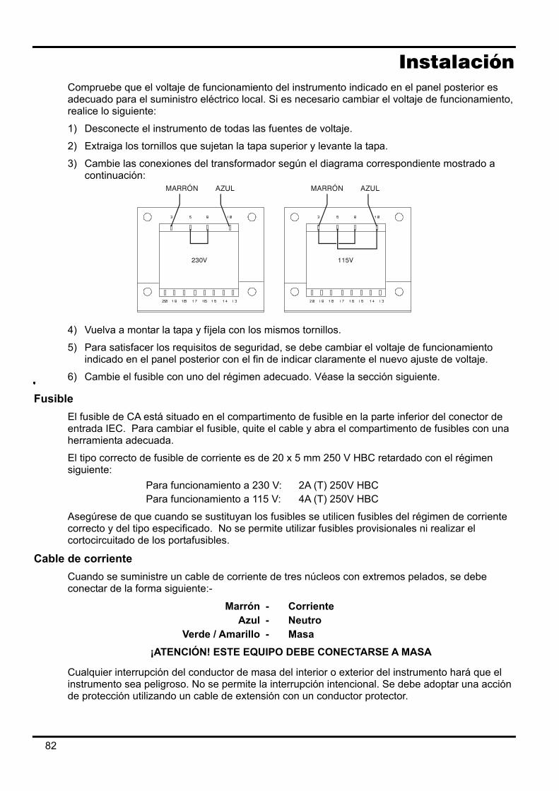
Instalación Compruebe que el voltaje de funcionamiento del instrumento indicado en el panel posterior es adecuado para el suministro eléctrico local. Si es necesario cambiar el voltaje de funcionamiento, realice lo siguiente:
1) Desconecte el instrumento de todas las fuentes de voltaje.
2) Extraiga los tornillos que sujetan la tapa superior y levante la tapa.
3) Cambie las conexiones del transformador según el diagrama correspondiente mostrado a continuación:
4) Vuelva a montar la tapa y fíjela con los mismos tornillos.
5) Para satisfacer los requisitos de seguridad, se debe cambiar el voltaje de funcionamiento indicado en el panel posterior con el fin de indicar claramente el nuevo ajuste de voltaje.
6) Cambie el fusible con uno del régimen adecuado. Véase la sección siguiente.
Fusible El fusible de CA está situado en el compartimento de fusible en la parte inferior del conector de entrada IEC. Para cambiar el fusible, quite el cable y abra el compartimento de fusibles con una herramienta adecuada.
El tipo correcto de fusible de corriente es de 20 x 5 mm 250 V HBC retardado con el régimen siguiente:
Para funcionamiento a 230 V: 2A (T) 250V HBC Para funcionamiento a 115 V: 4A (T) 250V HBC
Asegúrese de que cuando se sustituyan los fusibles se utilicen fusibles del régimen de corriente correcto y del tipo especificado. No se permite utilizar fusibles provisionales ni realizar el cortocircuitado de los portafusibles.
Cable de corriente Cuando se suministre un cable de corriente de tres núcleos con extremos pelados, se debe conectar de la forma siguiente:-
Marrón - Corriente Azul - Neutro
Verde / Amarillo - Masa ¡ATENCIÓN! ESTE EQUIPO DEBE CONECTARSE A MASA
Cualquier interrupción del conductor de masa del interior o exterior del instrumento hará que el instrumento sea peligroso. No se permite la interrupción intencional. Se debe adoptar una acción de protección utilizando un cable de extensión con un conductor protector.
82
Montaje Este instrumento se puede utilizar en un banco o montar en un soporte. Se suministra con patas para el montaje en banco. Las patas delanteras incluyen un mecanismo inclinable para ajustar el ángulo óptimo del panel. El fabricante o sus agentes internacionales puede suminitrar un kit de soporte para montar los suministros de corriente de la Serie QL. El soporte permitirá acomodar 1, 2 ó 3 unidades individuales, o una unidad triple y una unidad individual. También existe disponible una pieza de obturación para las posiciones que no se utilizan en el soporte.
Ventilación El suministro de corriente está refrigerado por un ventilador inteligente de varias velocidades que ofrece ventilación en la parte posterior. Tenga cuidado de no obstruir las entradas de aire en los paneles laterales o en la salida en la parte posterior. Cuando el instrumento esté montado en soporte, deje un espacio suficiente alrededor del instrumento y/o utilice una bandeja de ventilador para una refrigeración por aire forzado.
83
Conexiones Conexiones del panel frontal
La carga debe conectarse a los terminales positivo (rojo) y negativo (negro) con la marca OUTPUT (salida). Si es necesario, las conexiones de detección remota en la carga se realizan desde los terminales REMOTE SENSE (Detección Remota) positivo (+) y negativo (−).El funcionamiento de la detección remota se selecciona desde el teclado o a través de la interfaz de control remoto (sólo QL355P & QL564P); La luz REMOTE SENSE se enciende cuando se selecciona la detección remota. Si se desconecta la detección remota, el instrumento regresará a la detección local en los terminales de salida.
El terminal se conecta al bastidor y a la toma de tierra de seguridad.
Conexiones del panel posterior Terminales de salida (sólo QL355P & QL564P)
Los terminales de salida y detección están duplicados en el bloque de terminales roscados del panel posterior y tienen la marca Output +, Output −, Sense + y Sense − ; estas conexiones se corresponden con los equivalentes del panel frontal. El funcionamiento de la detección remota se selecciona desde el teclado o a través de la interfaz de control remoto. Cuando se utilizan los terminales del panel posterior, siempre deberá estar seleccionada la detección remota para garantizar que se mantiene la regulación de la salida dentro de las especificaciones.
RS232 (sólo QL355P & QL564P) Conector D de 9 patillas compatible con RS232 direccionable. Las conexiones de patillas se indican a continuación:
Patilla Nombre Descripción 1 − No hay conexión interna 2 TXD Datos transmitidos del instrumento 3 RXD Datos recibidos en el instrumento 4 − Sin conexión interna 5 GND Toma de tierra de señal 6 − Sin conexión interna 7 RXD2 Datos recibidos secundarios 8 TXD2 Datos transmitidos secundarios 9 GND Toma de tierra de señal
Las patillas 2, 3 y 5 se pueden utilizar como una interfaz convencional RS232 con comunicación XON/XOFF. Las patillas 7, 8 y 9 se utilizan cuando el instrumento se utiliza en modo RS232 direccionable. Las tomas de tierra de señal se conectan a la toma de tierra del instrumento. La dirección RS232 se ajusta desde el teclado.
GPIB (sólo QL355P & QL564P) La interfaz GPIB no está aislada; las tomas de tierra de señal GPIB se conectan a la toma de tierra del instrumento. Los subconjuntos implementados son los siguientes:
SH1 AH1 T6 TE0 L4 LE0 SR1 RL1 PP1 DC1 DT1 C0 E2 La dirección GPIB se ajusta desde el teclado.
84
USB (sólo QL355P & QL564P) El puerto USB se conecta a la toma de tierra del instrumento, y acepta un cable estándar USB. Las funciones plug-and-play Windows deben reconocer automáticamente que el instrumento ha sido conectado.
Salidas de alarma El conector embutido de 2 patillas con la marca Alarm permite acceder a un transistor de conmutación optoaislado NPN, cuya función se puede ajustar desde el teclado. Véase la sección Alarmas de este manual. El voltaje máximo de funcionamiento que se puede aplicar en los terminales es de 20 V CC y la corriente disipada máxima del ‘armazón’ del conmutador es de 1mA.
No aplique voltajes externos entre los terminales que sobrepasen los 30 V CC.
85
Funcionamiento inicial Esta sección del manual es una introducción general a los controles y el funcionamiento del instrumento, y debe leerse antes de conectar el suministro eléctrico por primera vez. En este manual, las teclas del panel frontal, las conexiones y los indicadores de pantalla se muestran en mayúsculas, ej. STORE (Guardar), ESCAPE (Cancelar), OUTPUT (Salida), JOG (Cambiar). Los mensajes mostrados en la pantalla de 7 segmentos se indican en un tipo de fuente distinto, ej.: StorE, GPIb, triP en mayúsculas o minúsculas con el fin de representar los caracteres según se muestran en la pantalla de 7 segmentos.
Encendido, Encendido/Apagado de la salida
El interruptor de corriente está situado en la parte inferior izquierda del panel frontal. En el encendido, la primera acción será restablecer los ajustes del instrumento a los valores que se hayan guardado automáticamente cuando se apagó el instrumento por última vez, aunque con la salida siempre desconectada. Sin embargo, el usuario puede cambiar este ajuste predeterminado de forma que se restaure también la salida en el encendido a su estado cuando se apagó. Véase la sección ‘Funciones adicionales’. La salida de CC se activa electrónicamente con la tecla ON/OFF; la tecla se enciende cuando la salida está encendida.
Teclado
Aquí se describen únicamente los principios de funcionamiento. El ajuste de los parámetros individuales se indica detalladamente en las secciones posteriores. La consideración principal en el diseño de la interfaz de usuario ha sido que los ajustes de cambio sean lo más ‘seguros’ posibles (es decir, con un riesgo mínimo de aplicar accidentalmente voltajes excesivos en un sistema final) y que el uso sea sencillo. Esto se ha conseguido solicitando al usuario que confirme (OK) los nuevos ajustes numéricos, con la opción de utilizar ESCAPE en cualquier punto o incluso detener el proceso hasta que se supera el tiempo asignado de funcionamiento y el instrumento regresa a sus valores originales. Además, un zumbador, teclas iluminadas, indicadores LED y mensajes de pantalla guían o advierten al usuario, de forma que los errores de control se reducen al mínimo. Cuando algunas de estas funciones (ej.: pitidos o indicadores parpadeantes) no sean necesarios por los usuarios habituales, pueden ser desactivadas. Véase la sección ‘Funciones adicionales’. En condiciones normales, el teclado numérico está desactivado. Si se pulsa una tecla el zumbador embitirá un doble pitido, lo que indicará un acción no permitida. Para ajustar un voltaje o corriente con el teclado, pulse la tecla NUMERIC SET (Ajuste numérico) V o I; la pantalla correspondiente mostrará 0·000V o 0·000A con el dígito a la izquierda de la coma decimal parpadeando. Los dígitos se introducen como respuesta al indicador parpadeante, junto con la coma decimal en el momento adecuado, y la entrada de datos se confirma con la tecla OK. Si no se pulsa OK antes de los 10 segundos de la última tecla numérica, la entrada se cancela y la pantalla regresa a su ajuste original. Si se pulsa ESCAPE en cualquier momento del procedimiento de entrada de datos, la entrada se cancela y la pantalla regresa a su ajuste original. La tecla OK se utiliza para confirmar la mayoría de entradas del teclado. En todos los demás casos, será la tecla VIEW V/I LIMITS (Ver límites V/I), y al pulsarla hará que la pantalla muestre el voltaje de salida preajustado y el límite de corriente durante 3 segundos. Durante este período parpadeará el indicador LIM en la pantalla.
86
Al pulsar SHIFT se encenderá la tecla y dará a las teclas numéricas las funciones marcadas encima (ej.: STORE, RECALL, etc.). Cuando se selecciona una función pulsando una de estas teclas, se cancela SHIFT (la tecla SHIFT ya no se enciende). Las pulsaciones de teclas adicionales necesarias para completar la función seleccionada se describen detalladamente en las secciones siguientes. Si no se pulsa ninguna tecla dentro de los 10 segundos para terminar la función, ésta finalizará como si se hubiera pulsado ESCAPE. SHIFT es una tecla conmutable; si se pulsa de nuevo SHIFT cuando se ha seleccionado cancelará SHIFT. SHIFT también se cancela mediante ESCAPE, o pulsando SET V o SET I.
Control Jog (cambio) El control giratorio jog (cambio) permite aumentar o disminuir el voltaje de salida o el límite de corriente en pasos con una resolución ajustada a través de las teclas JOG SET (Ajuste de cambio). La salida se indica inmediatamente después del ajuste, es decir, no se requiere confirmación mediante OK.
En el encendido, el cambio está siempre apagado. Para cambiar el ajuste de voltaje o corriente, pulse la tecla JOG SET V o I. La tecla se encenderá y el indicador JOG bajo el dígito que se ha modificado por última vez parpadeará. Cuando la tecla JOG SET V o I está encendida, cada vez que se pulsa la tecla V o I desplazará el indicador JOG un dígito a la izquierda; la selección ‘retorna’, de forma que cuando se ha alcanzado el mayor valor del incremento, la siguiente vez que se pulsa regresará a su valor inferior. La posición predeterminada en el encendido está bajo el dígito menos significativo, es decir, se selecciona el incremento inferior de cambio.
Si se gira el control giratorio de cambio en el sentido de las agujas del reloj o en el sentido contrario, aumentará o disminuirá el dígito seleccionado. Los dígitos a la izquierda del que se cambia aumenta o disminuye automáticamente cuando se alcanza el punto de exceso/insuficiencia de década. Los dígitos a la derecha del que se cambia siguen igual a menos que el paso de cambio supere o no llegue al máximo/mínimo de voltaje, en cuyo caso se ajustan a cero. Por ejemplo, 33,65V se ajusta en 34,65V se ajusta en 35,00V para el régimen 35V y un incremento de cambio de 1V; 0,160A se ajusta en 0,060A se ajusta en 0,001A para una disminución de cambio de 0,1A.
Los pasos que se pueden seleccionar son 1mV, 10mV, 100mV y 1mA, 10mA, 100mA. Si se ha seleccionado el régimen 500mA, los pasos de incremento de corriente son 0,1mA, 1mA, 10mA.
Para desactivar el control giratorio de cambio, pulse la tecla JOG SET OFF. Si se vuelve a seleccionar JOG SET V o I se activará el cambio en la posición del último dígito utilizado. El cambio no se cancela con una entrada numérica ni con ninguna de las funciones SHIFT, aunque está desactivada mientras dicha función está activada.
En el modo de voltaje constante con la salida activada, la pantalla derecha mostrará la corriente real en lugar del límite de corriente. Si se selecciona JOG SET I, el indicador JOG bajo el dígito seleccionado parpadeará a la mitad de velocidad (parpadeo lento). Para observar el efecto de cambiar el límite de corriente, será necesario desactivar la salida (para que la pantalla muestre permanentemente el límite de corriente) o pulsar VIEW V/I LIMITS, lo que hará que se muestre el límite de corriente hasta 3 segundos después de que se termine el movimiento del control de cambio. El parpadeo lento también se utiliza cuando se ha seleccionado JOG SET V. El voltaje real se mostrará porque el suministro está en el límite de corriente.
El ajuste predeterminado de fábrica es que el indicador JOG parpadea bajo el dígito seleccionado durante todo el momento que dicho cambio está seleccionado, de forma que el usuario siempre sabe qué parámetro se puede aumentar o disminuir. Cuando el usuario no considere adecuado que se le recuerde esto, a través de la opción Funciones adicionales puede hacer que parpadee el propio dígito. Por otra parte, cuando el parpadeo es intrusivo, el usuario puede hacer que no parpadee el indicador JOG (excepto cuando se muestra el parpadeo lento).
87
Pantalla La pantalla muestra el voltaje a la izquierda (5 dígitos) y la corriente a la derecha (4 dígitos). Estas pantallas de 7 segmentos también se utilizan para mostrar mensajes durante algunos ajustes de funciones (ej.: almacenamiento/recuperación de memoria o ajuste de dirección de control remoto) mediante el ‘conjunto de caracteres’ limitados que se pueden obtener con una pantalla de 7 segmentos. Estos conjuntos son necesariamente una mezcla de letras en mayúsculas y minúsculas. Por encima y por debajo de la pantalla de 7 segmentos existen varios indicadores ‘secretos hasta que estén encendidos’. A la derecha, por encima de la pantalla actual, están los indicadores que muestran el régimen de funcionamiento seleccionado: 35V/3A, 15V/5A o 35V/500mA (QL355); 56V/2A, 25V/4A, 56V/500mA (QL564). Los indicadores se encienden bajo el régimen impreso inmediatamente por encima de ellos y, en el caso del régimen 500mA, el indicador tiene la marca mA para destacar que la pantalla de corriente muestra ahora mA. Los otros indicadores por encima de la pantalla son los siguientes: CI, que indica que el instrumento está en modo de corriente constante; LIM, que parpadea cuando se pulsa la tecla VIEW V/I LIMITS para mostrar el voltaje/límite de corriente ajustado en la pantalla; REM, que se enciende cuando el instrumento se controla desde una interfaz remota (sólo QL355P & QL564P). Debajo de los tres dígitos menos significativos de las pantallas de voltaje y corriente están los indicadores JOG; el indicador correspondiente parpadea cuando se utiliza la función Jog (cambio). Veáse la sección Control Jog (cambio) anterior.
88
Funcionamiento manual Los nuevos usuarios deben leer el capítulo Funcionamiento inicial que describe los principios de funcionamiento del teclado y el control giratorio Jog (cambio).
Voltaje ajustado La pantalla izquierda muestra el voltaje ajustado con una resolución de 1mV, excepto cuando el instrumento está en modo de corriente constante (CI). En el modo CI, se mostrará el voltaje de salida real (que será inferior al voltaje ajustado) y la resolución de pantalla será de 10 mV. El dígito menos significativo (resolución de 1 mV) siempre se muestra como cero. El voltaje se puede ajustar directamente desde el teclado numérico; pulse la tecla NUMERIC SET V, introduzca el nuevo valor con las teclas numéricas y confime con OK. Los principios básicos de la entrada de datos con el teclado se describen en el capítulo Funcionamiento inicial, el cual debe ser leído por los nuevos usuarios. Cuando se pulsa SET V la pantalla muestra 0·000. A continuación deberá introducir un nuevo voltaje (ej.: 12,345V se introduce como 1, 2, ·, 3, 4, 5) y confirmarlo con OK. La posición de la coma decimal en la pantalla es fija para reducir el riesgo de introducir un valor incorrecto. Como consecuencia, y con el fin de evitar tener que introducir ceros iniciales (ej.: 2,345V se introduce como 2, ·, 3, 4, 5, OK), los números situados a la izquierda de la coma decimal son ligeramente diferentes a los números a la derecha de la coma decimal durante la introducción de números. Esto se hace evidente durante la introducción de números. El ajuste mínimo de voltaje es de 0,000V; el ajuste máximo es de 35,000V (15,000V en el régimen 15V/5A). Si pulsa OK en cualquier momento, se ajustará el voltaje introducido con todos los dígitos restantes ajustados en cero, ej.: 1, 2, ·, 3, OK ajustará 12,300V; 1, OK ajustará 1,000V. Si se pulsa OK inmediatamente después de SET V (mientras la pantalla muestra 0·000V), ajustará 0,000V. Si se pulsa ESCAPE en cualquier momento durante la secuencia, o no se pulsan más teclas después de 10 segundos de pulsar la anterior, la pantalla regresará a su lectura original antes de pulsarse SET V. Si se introduce un voltaje fuera del régimen máximo (incluso intentar introducir 3 dígitos antes de la coma decimal) o se intenta introducir más de 5 dígitos, hará que el zumbador emita dos pitidos. La última acción de tecla será ignorada. El voltaje también se podrá ajustar con el control de cambio (Jog). Si se pulsa JOG SET V se encenderá la tecla V y parpadeará el indicador JOG bajo el dígito que se haya cambiado por última vez. Mientras esté encendida la tecla V, cada vez que se pulse moverá el indicador JOG un dígito a la izquierda. La selección ‘retorna’, de forma que cuando se alcance el valor más alto del incremento, la siguiente vez que se pulse cambiará al más bajo. La posición predeterminada en el encendido está bajo el dígito menos significativo, es decir, se selecciona el incremento de cambio más bajo. Los intervalos de cambio que se pueden seleccionar son 1mV, 10mV y 100mV. Con el cambio (jog) activado, el voltaje de salida se puede aumentar o disminuir con el control giratorio de cambio con una resolución de paso indicada por la posición del indicador JOG parpadeante. La salida se indica inmediatamente después del ajuste, es decir, no se requiere confirmación mediante OK. Si la salida se ajusta en modo de corriente constante (el indicador CI parpadea) la pantalla izquierda mostrará el voltaje real, no el voltaje ajustado. Si se selecciona JOG SET V, el indicador JOG bajo el dígito seleccionado parpadeará a mitad de velocidad (parpadeo lento). Para observar el efecto de cambiar el voltaje ajustado, será necesario desconectar la salida (para que la pantalla muestre permanentemente el voltaje ajustado) o pulsar VIEW V/I LIMITS lo que provoca que se muestre el voltaje ajustado hasta 3 segundos después de que se detenga el movimiento del control de cambio (jog). Tenga en cuenta que en el modo de corriente constante, el voltaje real se mide y muestra solamente con una resolución de 10mV; el dígito de 1mV muestra permanentemente cero. Se pueden obtener más detalles del control de cambio en el capítulo Funcionamiento inicial.
89
Límite de corriente ajustado Con la salida desactivada, la pantalla derecha muestra el límite de corriente con una resolución de 1mA (0,1mA en el régimen 500mA). El límite de corriente se puede ajustar directamente desde el teclado numérico; pulse la tecla NUMERIC SET I, introduzca el nuevo valor con las teclas numéricas y confime con OK. Los principios básicos de la entrada de datos con el teclado se describen en el capítulo Funcionamiento inicial, el cual debe ser leído por los nuevos usuarios. Cuando se pulsa SET I la pantalla muestra 0,000. A continuación deberá introducir un nuevo voltaje (ej.: 1,234A se introduce como 1, · , 2, 3, 4,) y confirmarlo con OK. La posición de la coma decimal en la pantalla es fija para reducir el riesgo de introducir un valor incorrecto. Como consecuencia, y con el fin de evitar tener que introducir ceros iniciales (ej.: 0,234A se introduce como ·, 2, 3, 4, OK), los números situados a la izquierda de la coma decimal son ligeramente diferentes a los números a la derecha de la coma decimal durante la introducción de números. Esto se hace evidente durante la introducción de números. El ajuste mínimo de corriente es de 0,001A (0,1mA en el régimen 500mA); el ajuste máximo es de 3,000A, 5,000A o 500,0mA (QL355), 2,000A, 4,000A o 500,0mA (QL564), según el régimen, es decir, no hay capacidad de desbordamiento. Si pulsa OK en cualquier momento, se ajustará la corriente introducida con todos los dígitos restantes ajustados en cero, ej.: 1, ·, 2, OK ajustará 1,200A; 1, OK ajustará 1,000A. Si se pulsa OK inmediatamente después de SET V (mientras la pantalla muestra 0·000A), ajustará 0·00IA. Si se pulsa ESCAPE en cualquier momento durante la secuencia, o no se pulsan más teclas después de 10 segundos de pulsar la anterior, la pantalla regresará a su lectura original antes de pulsarse SET I. Si se introduce un voltaje fuera del régimen máximo (incluso intentar introducir 2 dígitos antes de la coma decimal) o se intenta introducir más de 4 dígitos, hará que el zumbador emita dos pitidos. La última acción de tecla será ignorada. El límite de corriente también se puede ajustar con el control de cambio (Jog). Si se pulsa JOG SET I se encenderá la tecla I y parpadeará el indicador JOG bajo el dígito que se haya cambiado por última vez. Mientras esté encendida la tecla I, cada vez que se pulse moverá el indicador JOG un dígito a la izquierda. La selección ‘retorna’, de forma que cuando se alcance el valor más alto del incremento, la siguiente vez que se pulse cambiará al más bajo. La posición predeterminada en el encendido está bajo el dígito menos significativo, es decir, se selecciona el incremento de cambio más bajo. Los intervalos de cambio que se pueden seleccionar son 1mA, 10mA y 100mA (0,1mA, 1mA y 10mA en el régimen 500 mA). Con el cambio (jog) activado, el límite de corriente se puede aumentar o disminuir con el control giratorio de cambio con una resolución de paso indicada por la posición del indicador JOG parpadeante. La salida se indica inmediatamente después del ajuste, es decir, no se requiere confirmación mediante OK. La salida en la pantalla derecha muestra la corriente real, no el límite de corriente (excepto en el modo de corriente constante). Si se selecciona JOG SET I, el indicador JOG bajo el dígito seleccionado parpadeará a mitad de velocidad (parpadeo lento). Para observar el efecto de cambiar el límite de corriente ajustado, será necesario desconectar la salida (para que la pantalla muestre permanentemente el voltaje ajustado) o pulsar VIEW V/I LIMITS, lo que provoca que se muestre el límite de corriente ajustado hasta 3 segundos después de que detenga el movimiento del control de cambio (jog).
90
Salida de corriente instantánea El control de límite de corriente se puede ajustar para limitar la corriente de salida continua a niveles de hasta 1mA (0,1 mA en el régimen 500mA). Sin embargo, comúnmente a todos los suministros de corriente en banco de precisión, un condensador está conectado a la salida para mantener la estabilidad y una respuesta transitoria correcta. Este condensador se carga en el voltaje de salida, y el cortocircuitado de la salida generará un impulso de corriente cuando el condensador se descarga, lo cual es independiente del ajuste del límite de corriente.
Selección de régimen El instrumento incorpora tres regímenes: 35V/3A, 15V/5A y 35V/500mA (QL355); 56V/2A, 25V/4A y 56V/500mA (QL564). El régimen seleccionado se muestra con un indicador encendido debajo del título correspondiente situado en el lateral superior derecho del instrumento. Cuando está seleccionado el régimen 35V/500mA, el texto del indicador es mA para indicar que el medidor de corriente muestra ahora miliamperios y no amperios. Para cambiar el régimen, pulse SHIFT seguido de RANGE o RANGE ; cada vez que se pulsa
RANGE se seleccionará el siguiente régimen a la izquierda; cada vez que se pulsa RANGE se seleccionará el siguiente régimen a la derecha. No hay ‘retorno’. Cuando se cambia el régimen, el indicador que representa el nuevo régimen y la tecla OK parpadearán. Al pulsar OK se ajustará el nuevo régimen. Para salir sin cambiar el régimen, pulse ESCAPE. Si se pulsa otra tecla en el modo de cambio de régimen, el zumbador emitirá dos pitidos y no se realizará ninguna otra acción. Si no se pulsa OK antes de los 10 segundos desde que se pulsó por última vez la tecla de cambio de régimen, la selección de régimen no cambiará. El régimen sólo se puede cambiar cuando la salida está desconectada. Si se pulsan las teclas RANGE o RANGE con la salida activada, parpadeará la tecla ON/OFF de salida (así como la tecla OK). La salida se puede desconectar con la tecla ON/OFF y el régimen se puede cambiar pulsando OK, o bien se puede pulsar OK directamente, en cuyo caso la salida se desconecta automáticamente y se puede cambiar el régimen. Si un cambio de régimen provoca que un voltaje o límite de corriente sobrepase el máximo correspondiente del nuevo régimen, el cambio de régimen se aceptará, aunque el ajuste se igualará al máximo del nuevo régimen. Tenga en cuenta que el ajuste de OVP no cambia cuando se cambia el régimen (ej.: un ajuste de OVP de 38V permanece válido en el régimen 15V). Si es necesario, el usuario podrá cambiar de forma independiente el ajuste de OVP.
Conexión a la carga La carga debe conectarse a los terminales OUTPUT positivo (rojo) y negativo (negro). Los dos son totalmente libres y se pueden conectar a la toma de tierra.
Detección remota El instrumento tiene una impedancia de salida muy baja aunque, inevitablemente, ésta aumenta por la resistencia de los cables de conexión. En corrientes elevadas, esto puede ocasionar diferencias significativas entre el voltaje primario indicado y el voltaje real de carga (por ejemplo, dos cables de conexión de 20mΩ disminuirán 0,2V a 5 Amps). Este problema se puede minimizar utilizando cables de conexión cortos y gruesos, aunque cuando sea necesario se puede solucionar completamente utilizando la capacidad de detección remota. Esto requiere conectar los terminales de detección a la salida en la carga en lugar de en la fuente. Introduzca los cables en los terminales de muelle REMOTE SENSE y conéctelos directamente en la carga. Seleccione la detección remota pulsando SHIFT, SENSE. La tecla OK parpadea y la luz situada por encima de los terminales de detección remota se encienden para mostar que se seleccionará la detección remota cuando se pulsa OK. Pulse OK para confirmar y ESCAPE para salir sin cambiar el estado. La detección remota se desactiva pulsando de nuevo SHIFT, SENSE. La tecla OK parpadea y la luz de detección remota se apaga para indicar que la detección remota se restablecerá cuando se pulse OK. Pulse OK para confirmar y ESCAPE para salir sin cambiar el estado.
91
Para evitar la inestabilidad y problemas de respuesta transitoria, se debe tener cuidado para garantizar un correcto acoplamiento entre cada salida y cable de detección. Esto se puede realizar uniendo los dos cables o utilizando un cable coaxial blindado (detección a través del interior). También puede ser ventajoso instalar un condensador electrolítico directamente en el punto de conexión de carga.
La caída de voltaje en cada cable de salida no debe ser superior a 0,5 voltios.
El QL355P & QL564P tiene terminales de salida y detección en el panel posterior para cuando se utilice el instrumento en un soporte. Los terminales de detección del panel posterior siempre se deben utilizar con las conexiones de salida del panel posterior.
Desconexión por error de conexión de la detección La salida se deconectará si el voltaje entre un terminal de salida y su correspondiente terminal de detección sobrepasa aproximadamente 1V. Esto tendrá lugar si los cables de detección se conectan en la carga en la salida incorrecta o si se intenta extraer corriente de los cables de detección.
Si los terminales de detección están conectados incorrectamente de esta forma, la pantalla muestra el mensaje SENSE triP y la salida se desconecta. Si se pulsa ESCAPE en este punto se borrará el mensaje y la pantalla mostrará el voltaje preajustado y el límite de corriente. Cuando se haya corregido la causa de la desconexión, la salida se puede conectar de nuevo.
Conexión en serie o paralelo con otras salidas Las salidas de alimentación son totalmente libres y se pueden utilizar en serie con otras unidades de alimentación para generar voltajes elevados de hasta 300 V CC.
El voltaje máximo admisible entre cualquier terminal y la toma de tierra ( ) es de 300 V CC.
¡ATENCIÓN! Estos voltajes son muy peligrosos y se debe tener mucho cuidado de proteger los terminales de salida para este uso. Bajo ninguna circunstancia se deben tocar los terminales de salida cuando se conecta la unidad para dicho uso. Todas las conexiones en los terminales se deben hacer con la alimentación desconectada en todas las unidades.
Debe tenerse en cuenta que la unidad sólo puede generar corriente y no puede absorberla, por lo que las unidades no se pueden conectar en serie en antifase.
La unidad se puede conectar en paralelo con otras unidades para generar corrientes más grandes. Cuando se conecten varias unidades en paralelo, el voltaje de salida será igual que el de la unidad con el mayor ajuste de voltaje de salida, hasta que la corriente extraída sobrepase su ajuste de límite de corriente; en este punto la salida disminuirá hasta el siguiente ajuste más alto y así sucesivamente. En el modo de corriente constante, las unidades se pueden conectar en paralelo para ofrecer una corriente igual a la suma de los ajustes de límite de corriente.
Tenga en cuenta que los terminales de salida tienen un régimen máximo de 15A. Si se utilizan varias salidas en paralelo para generar corrientes más grandes que ésta, la conexión se debe realizar en un punto separado, y no en uno de los terminales.
Protección de sobrevoltaje La protección de sobrevoltaje (OVP) se puede ajustar entre 1,0V y 40V (QL355), 1,0V y 62V (QL564). Si el voltaje de salida sobrepasa la OVP ajustada, la salida se cerrará automáticamente (normalmente a los 100µs), evitándose así daños en el circuito que se está comprobando. El circuito de OVP ofrecerá protección contra ajustes de voltajes excesivos accidentales desde el panel frontal o a través de las interfaces de control remoto, contra voltajes externos en los terminales de salida, o contra un fallo en los circuitos de control del propio instrumento.
Para ajustar la OVP, pulse SHIFT, OVP; el indicador JOG con el paso 100mV parpadeará y el control giratorio de cambio (jog) se podrá utilizar para aumentar o disminuir el ajuste de OVP en
92
pasos de 100mV. Pulse OK para confirmar el nuevo ajuste. Para salir sin introducir un nuevo valor, pulse ESCAPE. El ajuste predeterminado de fábrica es 40,0V (QL355), 62,0V (QL564). Si se deconecta la OVP, la pantalla mostrará el mensaje OUP triP y la salida se desconectará. Si se pulsa ESCAPE en este punto, se borrará el mensaje y la pantalla mostrará el voltaje preajustado y el límite de corriente. Cuando se haya eliminado la causa del OVP (o se haya cambiado el límite de OVP), la salida se podrá conectar de nuevo.
Tenga en cuenta que el ajuste de OVP no cambia cuando se cambia el régimen (ej.: un ajuste de OVP de 38V permanece válido en el régimen 15V). Si es necesario, el usuario podrá cambiar de forma independiente el ajuste de OVP.
También es posible y válido ajustar la OVP por debajo del voltaje ajustado. Si el suministro está en modo de corriente constante, el voltaje de salida estará por debajo del voltaje ajustado. La OVP se puede ajustar de forma que esté por encima del voltaje real de salida y por debajo del voltaje ajustado. Esto se puede utilizar para desconectar la salida bajo una condición de fallo que ha ocasionado un aumento de la impedancia de carga y un aumento consiguiente del voltaje real de salida por encima del punto de OVP.
Protección de sobrecorriente La protección de sobrecorriente (OCP) se puede ajustar entre 0,01A y 5,5A (QL355), 0,01A y 4,4A (QL564). Si la corriente de salida sobrepasa la OCP ajustada, la salida se cerrará automáticamente (normalmente a los 35ms).
Para ajustar la OCP, pulse SHIFT, OCP; el indicador JOG con el paso 10mA parpadeará y el control giratorio de cambio (jog) se podrá utilizar para aumentar o disminuir el ajuste de OCP en pasos de 10mA. Pulse OK para confirmar el nuevo ajuste. Para salir sin introducir un nuevo valor, pulse ESCAPE. El ajuste predeterminado de fábrica es 5,50A.
Si se deconecta la OCP, la pantalla mostrará el mensaje OCP triP y la salida se desconectará. Si se pulsa ESCAPE en este punto, se borrará el mensaje y la pantalla mostrará el voltaje preajustado y el límite de corriente. Cuando se haya eliminado la causa del OCP (o se haya cambiado el límite de OCP), la salida se podrá conectar de nuevo.
Al igual que con la OVP, tenga en cuenta que el ajuste de OCP no cambia cuando se cambia el régimen.
También es posible y válido ajustar la OCP por debajo del límite de corriente ajustado. Por ejemplo, el suministro eléctrico se puede utilizar para comprobar repetidamente una unidad bajo prueba, lo cual normalmente exige una corriente máxima de, por ejemplo, 2 amperios. Sin embargo, una unidad bajo prueba que sea defectuosa requerirá una corriente de más de 2 amperios y resultará dañada si se deja en un estado de corriente limitada de 2 amperios. En este caso, el límite de corriente se puede ajustar en 2,1A, por ejemplo, y la OCP se puede ajustar en 2,0A para garantizar que una unidad bajo prueba defectuosa desconectará el suministro eléctrico.
Protección de salida Además de la OVP y OCP que ofrecen una protección adicional de sobrevoltaje y sobrecorriente, la salida está protegida contra voltajes inversos mediante un diodo. La corriente inversa continua no debe sobrepasar los 3 amperios, aunque las corrientes transitorias pueden ser mucho mayores.
Potencia de salida (V x A) Si se pulsa SHIFT, V x A, el voltaje muestra el producto del voltaje de salida medido x la corriente medida y la pantalla de corriente muestra UA. V x A es una función momentánea, es decir, ofrece una lectura instantánea, no continua, de la potencia de salida. La lectura se mantiene mientras se pulsa la tecla. Al pulsar V x A se cancela SHIFT. Jog se desactiva provisionalmente (y los indicadores JOG se desactivan) durante la visualización de V x A.
93
Desconexión de temperatura Si se sobrepasa el límite de seguridad de temperatura interna, por ejemplo, porque se han bloqueado los orificios de ventilación del ventilador, la salida se desconecta y la pantalla mostrará OTP triP. Si se pulsa ESCAPE en este punto se ejecutará una de las siguientes acciones:
i. Si se ha eliminado ya la condición de sobretemperatura, el mensaje se borrará y la pantalla mostrará el voltaje preajustado y el límite de corriente. Si se ha solucionado la causa de la sobretemperatura, la salida se podrá conectar de nuevo.
ii. Si el instrumento está aún por encima del límite de seguridad de temperatura, el mensaje OTP triP parpadeará lentamente hasta que se haya enfriado el instrumento. En este punto la pantalla mostrará de nuevo el voltaje preajustado y el límite de corriente. Si se ha solucionado la causa de la sobretemperatura, la salida se podrá conectar de nuevo.
Salida de alarma El conector embutido de 2 clavijas en el panel posterior se conecta directamente a un transitor de conmutación NPN optoacoplado (clavija 1 emisor, clavija 2 captador) que se conecta (ej.: ‘cierre’ de conmutador) según las condiciones especificadas en la sección ‘Funciones adicionales’ descrita a continuación. El estado predeterminado es de cierre de conmutador para cualquier condición de desconexión (OVP, OCP, SENSE, OTP). El voltaje máximo de circuito abierto admisible en el conmutador es de 30 V CC y la corriente nominal absorbida para el cierre del conmutador es de 1mA.
Ajustes de almacenamiento El instrumento puede almacenar hasta 10 configuraciones en memoria no volátil. Los parámetros son régimen, voltaje, límite de corriente, OVP y OCP. El estado de salida y el ajuste de detección remota no se almacenan.
Para almacenar una configuración, pulse SHIFT, STORE, número de memoria., OK; el número de memoria es cualquier tecla entre 0 y 9.
Después de pulsar SHIFT, STORE, la pantalla muestra StorE - . La función SHIFT se cancela (la luz se apaga). En este punto, si se pulsa una tecla numérica se mostrará dicho número en lugar del signo – y mostrará E (memoria vacía) o F (memoria llena) junto al número, ej.: StorE 1.E, StorE 2.F . Se podrá comprobar cualquier número de memorias pulsando un número después del otro (es decir, sin tener que pulsar SHIFT, STORE cada vez) antes de confirmar la selección con la tecla OK. Una memoria completa se puede sobreescribir con los nuevos ajustes. En cualquier momento antes de pulsar la tecla OK, se puede salir de la función de almacenamiento sin guardar un ajuste pulsando ESCAPE o esperando 10 segundos desde la última entrada de datos.
Eliminar los ajustes almacenados Cualquier memoria se puede reajustar en ‘vacía’ de la forma siguiente: seleccione la memoria pulsando SHIFT, STORE, número de memoria.; A continuación pulse · . La pantalla muestra dELEt en lugar de StorE , ej.: dELEt 2.F Al pulsar OK se eliminará el contenido de la memoria.
Ajustes de recuperación Para recuperar un ajuste, pulse SHIFT, RECALL, número de memoria., OK; el número de memoria es cualquier tecla entre 0 y 9. Después de pulsar SHIFT, STORE, la pantalla muestra rECAL –. La función SHIFT se cancela (la luz se apaga). En este punto, si se pulsa cualquier tecla de 0 a 9 se previsualizarán los ajustes de voltaje y corriente de dicho número de memoria. Los ajustes parpadean para indicar el modo de previsualización.
Se puede previsualizar cualquier número de memorias pulsando un número después del otro (es decir, sin tener que pulsar SHIFT, RECALL cada vez) antes de confirmar la selección con la tecla
94
OK. Las memorias vacías vienen indicadas por el parpadeo de – en todas las posiciones de dígitos. En cualquier momento antes de pulsar la tecla OK, se puede salir de la función de recuperación sin recuperar un ajuste pulsando ESCAPE o esperando 10 segundos desde la última entrada de datos.
Los ajustes se pueden recuperar con la salida activada o desactivada. Sin embargo, si el ajuste recuperado implica un cambio de régimen, la salida se desconectará para evitar cualquier ‘perturbación’. Después de pulsar SHIFT, RECALL, número de memoria, la tecla ON/OFF parpadeará (junto con la tecla OK) si la recuperación implica un cambio de régimen. La salida se puede desconectar con la tecla ON/OFF y la recuperación se podrá completar pulsando OK, o bien se puede pulsar OK directamente, en cuyo caso la salida se desconecta automáticamente y se completará la recuperación.
Funciones adicionales El usuario puede ajustar variaciones de algunas funciones predeterminadas de fábrica utilizando la opción de funciones adicionales. Cada cambio de función, que se detallan en la lista siguiente, se accede pulsando SHIFT, #, nn, donde nn es el número de 2 dígitos de la lista. La luz SHIFT se apaga y el zumbador emitirá un pitido de confirmación cuando se haya introducido el número de 2 dígitos.
Nº de código Función 00 La salida siempre está desconectada en el encendido (ajuste predeterminado
de fábrica) 01 El estado de la salida en el encendido es el mismo que cuando se apagó el
instrumento por última vez
20 Salida de alarma ‘abierta’ para la salida desconectada y ‘cerrada’ para la salida conectada
21 (no se utiliza en la fuente de alimentación de una salida) 22 Salida de alarma ‘cerrada’ cuando se produce una desconexión de
sobretemperatura 23 Salida de alarma ‘cerrada’ cuando se produce una desconexión de detección 24 Salida de alarma ‘cerrada’ cuando se produce una desconexión de
sobrecorriente 25 Salida de alarma ‘cerrada’ cuando se produce una desconexión de
sobrevoltaje 26 Salida de alarma ‘cerrada’ cuando se produce cualquier desconexión (ajuste
predeterminado de fábrica)
30 Zumbador desconectado 31 Zumbador conectado (ajuste predeterminado de fábrica). Un solo pitido indica
la confirmación y un pitido doble indica una entrada de datos incorrecta.
40 El dígito de cambio (jog) parpadea; el indicador JOG sólo parpadea cuando el cambio está ‘oculto’
41 El indicador JOG parpadea siempre, excepto cuando está ‘oculto’ (ajuste predeterminado de fábrica),
42 El indicador JOG no parpadea, excepto cuando está ‘oculto’ (parpadeo lento)
91 Carga los parámetros de calibración predeterminados. Consulte el Manual de mantenimiento.
92 Muestra el número de versión de firmware en la pantalla 93 Ajusta estos ajustes de número al valor predeterminado de fábrica 99 Accede al modo de calibración. Consulte el manual de mantenimiento.
95
Ajustes predeterminados de fábrica Los ajustes predeterminados de fábrica (que se aplican cuando se enciende el instrumento por primera vez) son los siguientes:
Régimen: 35V/3A (QL355); 56V/2A (QL564)
Voltaje: 1,000V
Límite de corriente: 1,000A
OVP: 40V (QL355); 62V (QL564)
OCP: 5,5A (QL355); 4,4A (QL564)
Salida: Salida desconectada; Detección local
Ajustes de número: 00 Salida siempre desconectada en el encendido
26 Salida de alarma ‘cerrada’ cuando se produce cualquier desconexión
31 Zumbador conectado
41 El indicador JOG parpadea siempre; parpadeo lento cuando está oculto
RS232: 9.600 baudios (sólo QL355P & QL564P)
Dirección: 11 (sólo QL355P & QL564P)
Mensajes de error Los siguientes errores de hardware se indican con el número de error correspondiente en la pantalla. La tecla OK parpadeará y, si se pulsa, el error se ignorará y el funcionamiento continuará de la forma descrita.
Nº error Descripción del error Acción al pulsar OK
1 Las constantes de calibración están dañadas en el encendido
Carga los parámetros de calibración predeterminados
2 # funciones dañadas en el encendido Carga los ajustes # predeterminados
3 Los ajustes de apagado no están cargados correctamente en el encendido
Carga los ajustes de encendido predeterminados de fábrica
Si se apaga el instrumento con los mensajes de error mostrándose, no se modificarán los ajustes
Mantenimiento Los fabricantes o sus agentes en el extranjero pueden proporcionar un servicio de reparaciones para las unidades averiadas. En caso de que los propietarios deseen realizar el trabajo de mantenimiento por su cuenta, únicamente lo deberá realizar personal cualificado según el manual de mantenimiento, que se puede adquirir directamente del fabricante o de sus agentes en el extranjero.
Limpieza En caso de que deba limpiar el instrumento, utilice un paño ligeramente humedecido con agua o con un detergente suave.
ADVERTENCIA - PARA EVITAR DESCARGAS ELÉCTRICAS Y DAÑOS EN EL INSTRUMENTO, NO PERMITA QUE ENTRE AGUA DENTRO DE LA CAJA, Y PARA EVITAR DAÑOS EN LA CAJA NO LA LIMPIE NUNCA CON DISOLVENTE.
96

Thurlby Thandar Instruments Ltd Glebe Road, Huntingdon, Cambridgeshire PE29 7DR, England
Telephone: +44(0)1480 412451 Fax: +44(0)1480 450409 International website: www.tti−test.com UK website: www.tti.co.uk
e mail: [email protected]
Book Part No. 48511-0500 Issue 4