Embed Size (px)
Citation preview

INSTRUCTION MANUALPhone: 1-360-734-3482 • On-Line Technical Support: [email protected]
COPYRIGHT © DECEMBER 2003 BY WOODSTOCK INTERNATIONAL, INC. REVISED OCTOBER, 2008.WARNING: NO PORTION OF THIS MANUAL MAY BE REPRODUCED IN ANY SHAPE OR FORM WITHOUT
THE WRITTEN APPROVAL OF WOODSTOCK INTERNATIONAL, INC.
MODEL W1669 and W1670RADIAL DRILL PRESS
#6218CR Printed in China

WARNINGSome dust created by power sanding, sawing, grind-ing, drilling, and other construction activities con-tains chemicals known to the State of California to cause cancer, birth defects or other reproductive harm. Some examples of these chemicals are:
• Lead from lead-based paints. • Crystalline silica from bricks, cement, and other masonry products. • Arsenic and chromium from chemically treated lumber.
Your risk from these exposures varies, depending on how often you do this type of work. To reduce your exposure to these chemicals: work in a well venti-lated area, and work with approved safety equip-ment, such as those dust masks that are specially designed to filter out microscopic particles.
-1-
ASSEM
BLYO
PERATIO
NS
MA
INTEN
AN
CEELECTRICA
LA
DJU
STMEN
TSSA
FETYIN
TROD
UCTIO
N
CONTENTSINTRODUCTION............................................................................................. 2
About the W1669 and W1670 Radial Drill Presses ......................................................... 2Woodstock Technical Support ................................................................................. 2
SAFETY....................................................................................................... 4Standard Safety Instructions .................................................................................. 4Additional Safety Instructions for Drill Presses ............................................................ 5Avoiding Potential Injuries .................................................................................... 6
ELECTRICAL................................................................................................. 7110V Operation ................................................................................................. 7Extension Cords ................................................................................................. 7Grounding ........................................................................................................ 7
ASSEMBLY.................................................................................................... 8Base and Column ............................................................................................... 9Table Support ................................................................................................. 10Headstock ...................................................................................................... 12Drill Chuck and ............................................................................................... 13Spindle ......................................................................................................... 13
ADJUSTMENTS.............................................................................................14Belt Tension ................................................................................................... 14Feed Shaft Spring Tension ................................................................................... 15Quill-Shaft Screw ............................................................................................. 16Table ............................................................................................................ 17
OPERATIONS...............................................................................................18Test Run ........................................................................................................ 18Headstock ...................................................................................................... 19Changing Drill Bits ............................................................................................ 20Speed Changes ................................................................................................ 21Drill Press RPM Chart ......................................................................................... 22Drilling Depth ................................................................................................. 22Drill, Cutter, and Hole Saw Suggested RPM Chart .................................................. 23
MAINTENANCE.............................................................................................25General ......................................................................................................... 25Table and Base ................................................................................................ 25Lubrication .................................................................................................... 25Troubleshooting ............................................................................................... 26W1669 and W1670 Drill Press 110V Wiring ............................................................... 27W1669 and W1670 Parts ..................................................................................... 28W1669 Parts ................................................................................................... 30W1670 Parts ................................................................................................... 32Accessories .................................................................................................... 34Notes ........................................................................................................... 36Warranty ....................................................................................................... 38

-2-
The SHOP FOX® Model W1669 and W1670 Radial Drill Presses have been specially designed by Woodstock International, Inc. to provide many years of trouble free service. Close attention to detail, ruggedly built parts and a rigid quality control program assure safe and reliable operation.
The Model W1669 and W1670 Radial Drill Presses are capable of a wide variety of drilling and sanding operations. Purchasing the D2677 Drum Sander Set and D2722 Mandrel allows you to sand small or finely detailed pieces. The tilting table and headstock allows surfaces to be sanded and drilled at many different angles. The Model W1669 and W1670 is packaged with a drill chuck, motor and paddle switch with remov-able safety key.
Woodstock International, Inc. is committed to customer satisfaction in providing this manual. It is our intent to make sure all the information necessary for safety, ease of assembly, practical use and dura-bility of this product be included.
Woodstock.Technical.Support
About.the.W1669.and.W1670.Radial.Drill.PressesINTRODUCTION
INTR
OD
UCT
ION
We stand behind our machines! In the event that questions arise about your machine, parts are miss-ing, or a defect is found, please contact Woodstock International Technical Support at 1-360-734-3482 or send e-mail to: [email protected]. Our knowledgeable staff will help you troubleshoot prob-lems and send out parts for warranty claims.
If you need the latest edition of this manual, you can download it from http://www.shopfox.biz. If you still have questions after reading the latest manual, or if you have comments please contact us at:
Woodstock.International,.Inc.Attn:.Technical.Support.Department
P.O..Box.2309Bellingham,.WA.98227
-3-
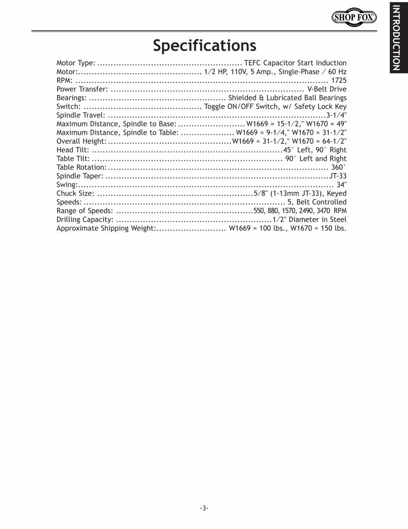
Motor Type: ...................................................... TEFC Capacitor Start InductionMotor: .............................................. 1⁄2 HP, 110V, 5 Amp., Single-Phase ⁄ 60 HzRPM: .............................................................................................. 1725Power Transfer: ........................................................................ V-Belt DriveBearings: ................................................... Shielded & Lubricated Ball BearingsSwitch: ............................................ Toggle ON/OFF Switch, w/ Safety Lock KeySpindle Travel: .................................................................................3-1⁄4''Maximum Distance, Spindle to Base: ......................... W1669 = 15-1⁄2,'' W1670 = 49''Maximum Distance, Spindle to Table: .................... W1669 = 9-1⁄4,'' W1670 = 31-1⁄2''Overall Height: ..............................................W1669 = 31-1⁄2,'' W1670 = 64-1⁄2''Head Tilt: .......................................................................45° Left, 90° RightTable Tilt: ....................................................................... 90° Left and RightTable Rotation: .................................................................................. 360°Spindle Taper: ...................................................................................JT-33Swing: ............................................................................................... 34'' Chuck Size: ..........................................................5⁄8'' (1-13mm JT-33), KeyedSpeeds: ........................................................................... 5, Belt ControlledRange of Speeds: ...................................................550, 880, 1570, 2490, 3470 RPM Drilling Capacity: ..........................................................1⁄2'' Diameter in SteelApproximate Shipping Weight: .......................... W1669 = 100 lbs., W1670 = 150 lbs.
Specifications
INTRO
DU
CTION

-4-
READ.MANUAL.BEFORE.OPERATING.MACHINEFAILURE.TO.FOLLOW.INSTRUCTIONS.BELOW.WILL.
RESULT.IN.PERSONAL.INJURY
1.. Thoroughly.read.the.instruction.manual.before.operating.your.machine..Learn the applications, limitations and potential hazards of this machine. Keep manual in a safe, convenient place for future reference.
2. Keep.work.area.clean.and.well.lighted..Clutter and inadequate lighting invite potential hazards.
3. Ground.all.tools..If a machine is equipped with a three-prong plug, it must be plugged into a three-hole electrical outlet or grounded extension cord. If using an adapter to aid in accommodat-ing a two-hole receptacle, ground the adapter using a screw to a known ground.
4. Wear.eye.protection.at.all.times..Use safety goggles with side shields or safety goggles, meeting the national safety standards, while operating this machine.
5. Avoid.dangerous.environments..DO.NOT operate this machine in wet or open flame environ-ments. Airborne dust particles could cause an explosion and severe fire hazard.
6. Ensure.all.guards.are.securely.in.place.and in working condition.
7. Make.sure.switch.is.in.the.“OFF”.position.before connecting power to machine.
8. Keep.work.area.clean;.free of clutter, grease, etc.
9. Keep.children.and.visitors.away..All visitors should be kept at a safe distance away while operat-ing unit.
10. Childproof.your.workshop.with padlocks, master switches, or by removing starter keys.
11. Disconnect.the.machine.when.cleaning,.adjusting,.or.servicing.
Indicates an imminently hazardous situation which, if not avoided, WILL result in death or serious injury.
Indicates a potentially hazardous situation which, if not avoided, COULD result in death or serious injury.
Indicates a potentially hazardous situation which, if not avoided, MAY result in minor or moderate injury and damage to the machine. It may also be used to alert against unsafe practices.
This symbol is used to alert the user to useful information about proper operation of the equipment.NOTICE
SAFETY
Standard.Safety.Instructions
SAFE
TY
1.. DRILL.PRESS.SPEEDS..Always operate your drill press at speeds that are appropriate for the drill bit size and the material that you are drilling.
2.. DRILLING.HOLES. Feed the drill bit evenly into the workpiece. Back the bit out of deep holes and clear the chips with a brush after you have turned the machine off.
3.. USING.THE.CORRECT.DRILL.BITS. Use only round, hex or triangular shank drill bits, and make sure the drill bit you are using is tightened properly..
4.. SAFE.MAINTENANCE. Never do maintenance or change speeds with this machine plugged in.
5.. USING.SERVICEABLE.TOOLS. Never use tools that are in poor condition. Cutting tools that are dull or damaged are difficult to control and may cause serious injury.
6.. DRILLING.OPERATIONS. Never hold a workpiece by hand while drilling, never drill sheet metal unless it is clamped securely to the table, and always secure the workpiece to the table before drilling.
7.. SECURING.A.WORKPIECE. Properly position workpieces to avoid drilling into the table.
8.. PROTECTING.YOUR.EYES. A face guard used or safety goggles is recommended.
9.. WORKING.HABITS. Habits – good and bad – are hard to break. Develop good habits in your shop and safety will become second-nature to you.
-5-
12. DO.NOT.force.the.tool..The machine will do a safer and better job at the rate for which it was designed.
13. Use.correct.tool..DO.NOT force machine or attachment to do a job for which it was not designed.
14. Wear.proper.apparel..DO.NOT wear loose clothing, neck ties, gloves, jewelry; and tie back hair.
15. Remove.adjusting.keys.and.wrenches..Before turning the machine on, make it a habit to check that all adjusting keys and wrenches have been removed.
16. Use.proper.extension.cord..When using an extension cord, make sure it is in good condition. When extension cord is 100 feet and less in length, use those that are rated Standard Service (grade S) or better, and that have a conductor size of 16 AWG. A drop in line voltage, loss of power and overheating can result when using an undersized cord. The extension cord should have a ground wire and ground plug pin, as well.
17. Keep.proper.footing.and.balance at all times.
18. DO.NOT.leave.machine.unattended..Wait until it comes to a complete stop before leaving the area.
19. Perform.machine.maintenance.and.care..Follow lubrication and accessory attachment instruc-tions in the manual.
20. Keep.machine.away.from.open.flame..Operating machines near pilot lights and/or open flames creates a high risk if dust is dispersed in the area. Dust particles and an ignition source may cause an explosion. DO.NOT operate the machine in high risk areas, including but not limited to, those mentioned above.
Additional.Safety.Instructions.for.Drill.Presses
SAFETY
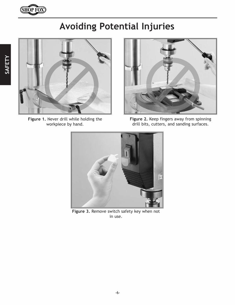
Figure.1..Never drill while holding the workpiece by hand.
Figure.2. Keep fingers away from spinning drill bits, cutters, and sanding surfaces.
Figure.3. Remove switch safety key when not in use.
-6-
Avoiding.Potential.Injuries
SAFE
TY
-7-
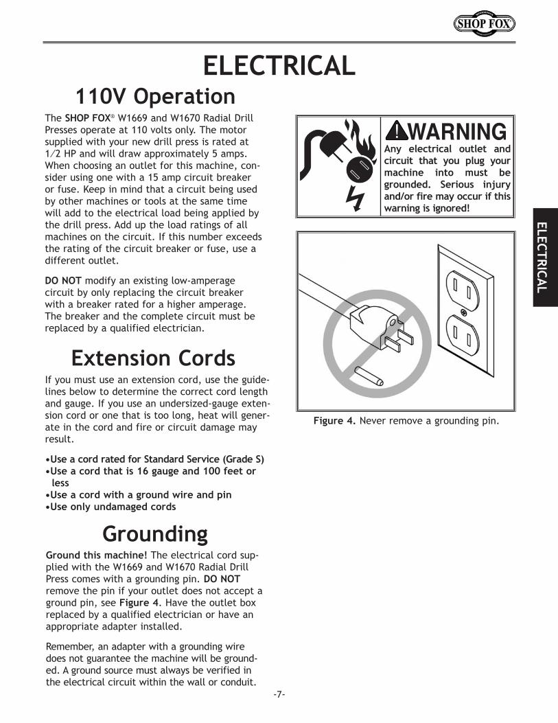
Ground.this.machine! The electrical cord sup-plied with the W1669 and W1670 Radial Drill Press comes with a grounding pin. DO.NOT remove the pin if your outlet does not accept a ground pin, see Figure.4. Have the outlet box replaced by a qualified electrician or have an appropriate adapter installed.
Remember, an adapter with a grounding wire does not guarantee the machine will be ground-ed. A ground source must always be verified in the electrical circuit within the wall or conduit.
Grounding
ELECTRICAL110V.Operation
The SHOP FOX® W1669 and W1670 Radial Drill Presses operate at 110 volts only. The motor supplied with your new drill press is rated at 1⁄2 HP and will draw approximately 5 amps. When choosing an outlet for this machine, con-sider using one with a 15 amp circuit breaker or fuse. Keep in mind that a circuit being used by other machines or tools at the same time will add to the electrical load being applied by the drill press. Add up the load ratings of all machines on the circuit. If this number exceeds the rating of the circuit breaker or fuse, use a different outlet.
DO.NOT modify an existing low-amperage circuit by only replacing the circuit breaker with a breaker rated for a higher amperage. The breaker and the complete circuit must be replaced by a qualified electrician.
Any. electrical. outlet. and.circuit. that. you. plug. your.machine. into. must. be.grounded.. Serious. injury.and/or.fire.may.occur.if.this.warning.is.ignored!
Figure.4..Never remove a grounding pin.
If you must use an extension cord, use the guide-lines below to determine the correct cord length and gauge. If you use an undersized-gauge exten-sion cord or one that is too long, heat will gener-ate in the cord and fire or circuit damage may result.
•Use.a.cord.rated.for.Standard.Service.(Grade.S)•Use.a.cord.that.is.16.gauge.and.100.feet.or...........less•Use.a.cord.with.a.ground.wire.and.pin•Use.only.undamaged.cords
Extension.Cords
ELECTRICAL

-8-
EYE.HAZARD!Wear. safety. goggles. during.all. assembly. procedures..Otherwise. serious. personal.injury.may.occur!
ASSEMBLY.
Figure.5..Component inventory.
A.. Headstock AssemblyB.. BaseC.. ColumnD.. TableE.. Table Bracket Assembly F.. Drill Chuck and KeyG.. Spindle Handles and Knobs (3)H.. W1669: Hex Wrenches 3MM, 5MM, 10MM
I.. Column Bolts (4)J.. Belt Cover Knob and ScrewK.. Lift Handle CrankL.. Pinion GearM.. Lock Handles (4) N.. RackO.. Column RingP.. Open End Wrench (Not shown)Q..W1670: Lock Lever
G
D
OL
I
C
N
S
H
M
K
E
F
J
B
Q
Use the list below and Figure.5 to inventory your shipment before beginning assembly. If any parts are missing, call Woodstock International, Inc. at 360-734-3482 or [email protected].
While the main components of the SHOP FOX® W1669 and W1670 Drill Presses are assembled at the fac-tory, some assembly is required. The following order of procedures is the recommended sequence.
R.. W1670: Table Support Arm BracketS.. W1670: Hex Wrenches, 3MM and 5mm T.. Mounting Hardware (Refer to the parts list on Page.30.for details)
Use the parts list at the back of this manual when ordering parts.
.SUFFOCATION.HAZARD!Immediately..discard.all.plastic.bags.and.packing.materials.to.eliminate. a. suffocation. haz-ard.for.children.and.animals.
R
T
A
ASS
EMBL
Y
-9-
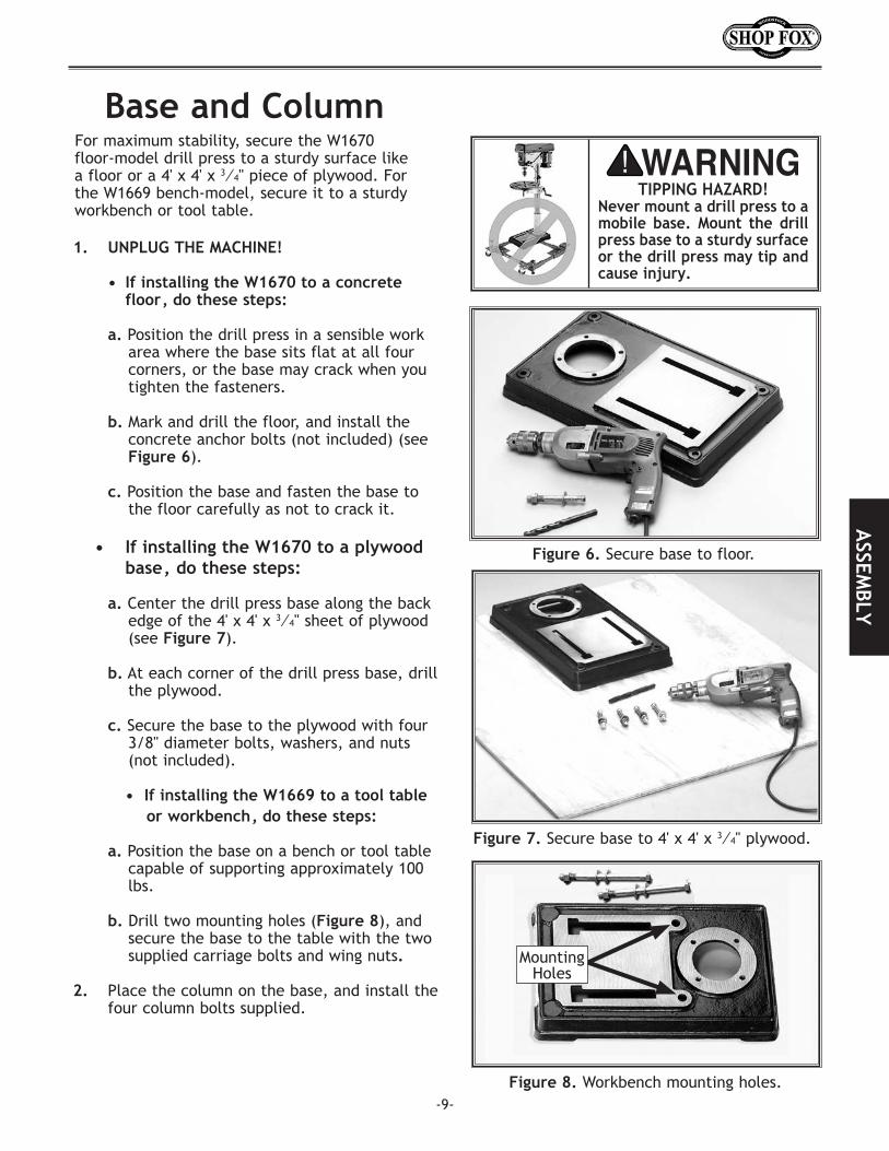
Figure.6..Secure base to floor.
Figure.7..Secure base to 4' x 4' x 3⁄4" plywood.
Base.and.Column
1.. UNPLUG.THE.MACHINE!
. •. If.installing.the.W1670.to.a.concrete.. .. floor,.do.these.steps:
a. Position the drill press in a sensible work area where the base sits flat at all four corners, or the base may crack when you tighten the fasteners.
b. Mark and drill the floor, and install the concrete anchor bolts (not included) (see Figure.6).
c. Position the base and fasten the base to the floor carefully as not to crack it.
. . •. If.installing.the.W1670.to.a.plywood.. .
. . base,..do.these.steps:
a. Center the drill press base along the back edge of the 4' x 4' x 3⁄4" sheet of plywood (see Figure.7).
b. At each corner of the drill press base, drill the plywood.
c. Secure the base to the plywood with four 3/8" diameter bolts, washers, and nuts (not included).
. . . •..If.installing.the.W1669.to.a.tool.table.... . ....or.workbench,.do.these.steps:
a. Position the base on a bench or tool table capable of supporting approximately 100 lbs.
b. Drill two mounting holes (Figure.8), and secure the base to the table with the two supplied carriage bolts and wing nuts.
2.. Place the column on the base, and install the four column bolts supplied.
For maximum stability, secure the W1670 floor-model drill press to a sturdy surface like a floor or a 4' x 4' x 3⁄4" piece of plywood. For the W1669 bench-model, secure it to a sturdy workbench or tool table.
TIPPING.HAZARD!Never.mount.a.drill.press.to.a.mobile. base.. Mount. the. drill.press.base.to.a.sturdy.surface.or.the.drill.press.may.tip.and.cause.injury..
Figure.8..Workbench mounting holes.
Mounting Holes
ASSEM
BLY

-10-Figure.11..Installing rack and table bracket.
Figure.10..Align set screw with flat pad on pinion.
Table.SupportThe W1669 comes with a one geared table bracket. The W1670 comes with a geared table bracket and table support arm, which allows the distance between the column and table to be adjusted. No table support parts are inter-changeable between the two drill presses.
To.install.the.table.support.assembly,.do.these.steps:
1.. Insert the table lock lever through the un-threaded hole (see Figure.9) in the table bracket, and then tighten the lever into the threaded side exactly three turns.
2.. Starting with the pinion gear, insert the shaft into the table bracket and mesh the teeth with the worm gear as shown in Figure.9..
3.. Align the set screw in the crank handle with the flat pad on pinion shaft.
4.. Tighten the 3mm set screw to lock the handle in place (see Figure.10).
5.. Examine the rack and note that the rack teeth at one end are cut closer to the end of the rack than the other.
6. Insert the rack through the table bracket so the end that has the rack teeth cut clos-er to the end is pointing down (see Figure.11).
7. Hold the rack against the worm gear and slide the table bracket and rack onto the column (see Figure.11).
Figure.9..Pinion and worm gear installation.
Pinion Gear
WormGear
Un-threaded Hole
Flat Pad
Set ScrewASS
EMBL
Y

Figure.13..Column ring in the correct position.
8. Seat the rack tapered-point into the bevel that is cut into the column support tube (see Figure.12).
9. Slide the column ring onto the column with the inside bevel in the down position until the rack tapered-point seats into the bevel (see Figure.13).
10. Position the column ring so the table bracket and rack can just rotate around the column without binding.
11. Carefully, snug the set screw to hold the column ring in place. Over-tightening the column ring will distort or split the column ring.
Column Ring Bevel
Figure.12..Bevel and rack seated correctly.
Tapered Rack Point and
Column Support Tube Bevel.
Set Screw
ASSEM
BLY
-11-
-12-
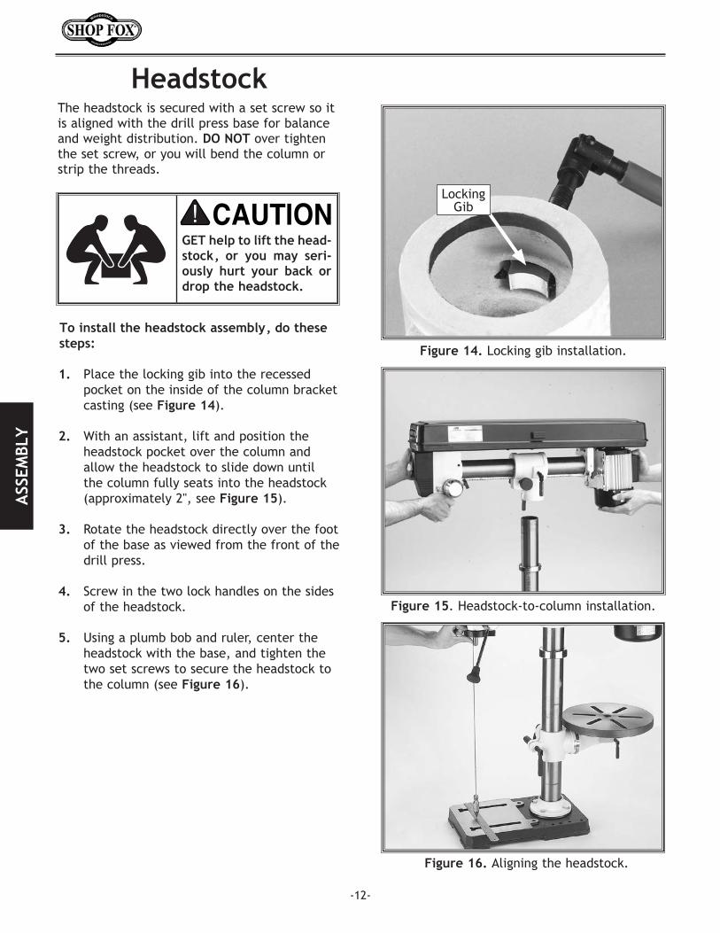
GET.help.to.lift.the.head-stock,. or. you. may. seri-ously. hurt. your. back. or.drop.the.headstock..
The headstock is secured with a set screw so it is aligned with the drill press base for balance and weight distribution. DO.NOT over tighten the set screw, or you will bend the column or strip the threads.
Headstock
To.install.the.headstock.assembly,.do.these.steps:
1.. Place the locking gib into the recessed pocket on the inside of the column bracket casting (see Figure.14).
2. With an assistant, lift and position the headstock pocket over the column and allow the headstock to slide down until the column fully seats into the headstock (approximately 2", see Figure.15).
3.. Rotate the headstock directly over the foot of the base as viewed from the front of the drill press.
4. Screw in the two lock handles on the sides of the headstock.
5. Using a plumb bob and ruler, center the headstock with the base, and tighten the two set screws to secure the headstock to the column (see Figure.16).
Figure.14..Locking gib installation.
Figure.15. Headstock-to-column installation.
Figure.16..Aligning the headstock.
Locking Gib
ASS
EMBL
Y
-13-
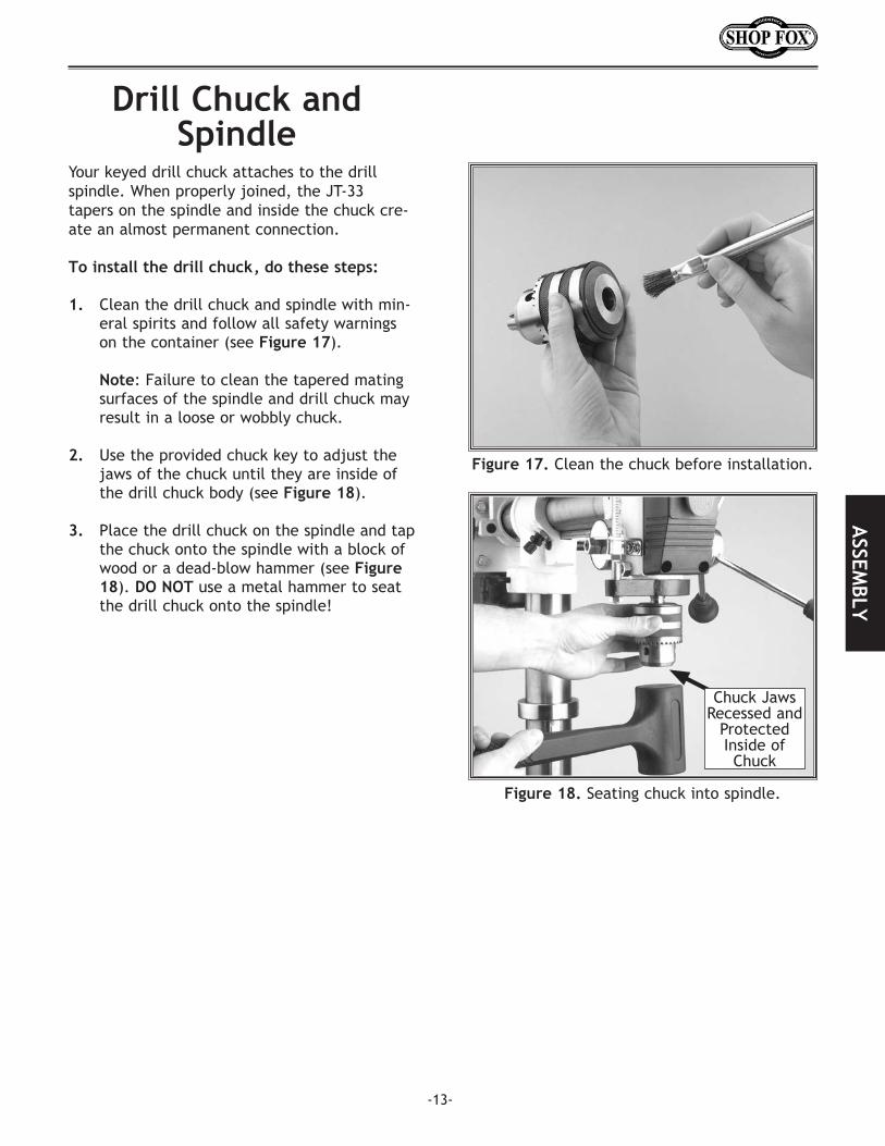
Drill.Chuck.and.Spindle
Your keyed drill chuck attaches to the drill spindle. When properly joined, the JT-33 tapers on the spindle and inside the chuck cre-ate an almost permanent connection.
To.install.the.drill.chuck,.do.these.steps:
1... Clean the drill chuck and spindle with min-eral spirits and follow all safety warnings on the container (see Figure.17).
Note: Failure to clean the tapered mating surfaces of the spindle and drill chuck may result in a loose or wobbly chuck.
2. Use the provided chuck key to adjust the jaws of the chuck until they are inside of the drill chuck body (see Figure.18).
3. Place the drill chuck on the spindle and tap the chuck onto the spindle with a block of wood or a dead-blow hammer (see Figure.18). DO.NOT.use a metal hammer to seat the drill chuck onto the spindle!
Figure.18..Seating chuck into spindle.
Figure.17..Clean the chuck before installation.
Chuck Jaws Recessed and
Protected Inside of Chuck
ASSEM
BLY

-14-
ADJUSTMENTSBelt.Tension
During the life of your drill press you will use differ-ent belt and pulley combinations. No matter which pulley combination you use, make sure that the belt is tensioned properly
To.adjust.the.drive.belt.tension,.do.these.steps:
1... UNPLUG.THE.DRILL.PRESS!.
2... Open the belt safety cover (see Figure.19).
3.. Loosen both motor lock knobs at the side of the headstock (see Figure.).
4... Slide the motor away from the headstock until the belt is taut.
5... Hold the motor in position, and tighten the lock screw, and make sure the belt deflec-tion gap is correct when pinched together between the pulleys (see Figure.21).
• If the gap between both inner sides of the belt is greater or less than 3⁄4" repeat Steps.3-5 until the deflection gap is 3⁄4".
• If the deflection gap is 3⁄4" the belt is ten-sioned correctly.
6... Close the belt safety cover.
UNPLUG. the. drill. press..before. any. assembly,.adjustment,. maintenance,.or. belt. changing. proce-dures.. Otherwise. serious.personal.injury.may.occur!
Figure.19..Open belt safety cover.
Figure.20..Motor lock knob.
Figure.21..Measuring belt deflection.
Motor Lock Knob
Push rod
Belt Deflection gap should be
about 3⁄4"
AD
JUST
MEN
TS
-15-
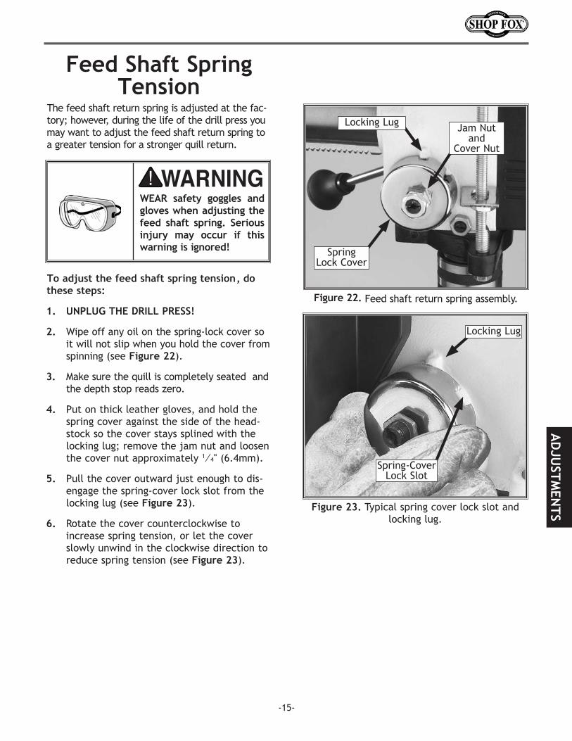
Figure.23. Typical spring cover lock slot and locking lug.
Spring-Cover Lock Slot
Locking Lug
Figure.22..Feed shaft return spring assembly.
Spring Lock Cover
Jam Nut and
Cover Nut
The feed shaft return spring is adjusted at the fac-tory; however, during the life of the drill press you may want to adjust the feed shaft return spring to a greater tension for a stronger quill return.
To.adjust.the.feed.shaft.spring.tension,.do.these.steps:
1... UNPLUG.THE.DRILL.PRESS!
2... Wipe off any oil on the spring-lock cover so it will not slip when you hold the cover from spinning (see Figure.22).
3... Make sure the quill is completely seated and the depth stop reads zero.
4.. Put on thick leather gloves, and hold the spring cover against the side of the head-stock so the cover stays splined with the locking lug; remove the jam nut and loosen the cover nut approximately 1⁄4" (6.4mm).
5... Pull the cover outward just enough to dis-engage the spring-cover lock slot from the locking lug (see Figure.23).
6... Rotate the cover counterclockwise to increase spring tension, or let the cover slowly unwind in the clockwise direction to reduce spring tension (see Figure.23).
Feed.Shaft.Spring.Tension
WEAR. safety. goggles. and.gloves.when.adjusting.the.feed. shaft. spring.. Serious.injury. may. occur. if. this.warning.is.ignored!
AD
JUSTM
ENTS
Locking Lug
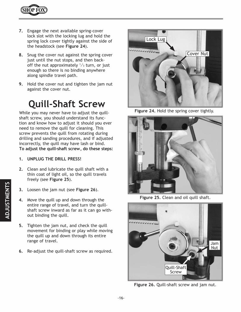
While you may never have to adjust the quill-shaft screw, you should understand its func-tion and know how to adjust it should you ever need to remove the quill for cleaning. This screw prevents the quill from rotating during drilling and sanding procedures, and if adjusted incorrectly, the quill may have lash or bind.To.adjust.the.quill-shaft.screw,.do.these.steps:
1. UNPLUG.THE.DRILL.PRESS!.
2... Clean and lubricate the quill shaft with a thin coat of light oil, so the quill travels freely (see Figure.25).
3... Loosen the jam nut (see Figure.26).
4... Move the quill up and down through the entire range of travel, and turn the quill-shaft screw inward as far as it can go with-out binding the quill.
5... Tighten the jam nut, and check the quill movement for binding or play while moving the quill up and down through its entire range of travel.
6... Re-adjust the quill-shaft screw as required.
Figure.25..Clean and oil quill shaft.
Figure.26..Quill-shaft screw and jam nut.
Quill-Shaft Screw
Jam Nut
7... Engage the next available spring-cover lock slot with the locking lug and hold the spring lock cover tightly against the side of the headstock (see Figure.24).
8... Snug the cover nut against the spring cover just until the nut stops, and then back-off the nut approximately 1⁄3 turn, or just enough so there is no binding anywhere along spindle travel path.
9... Hold the cover nut and tighten the jam nut against the cover nut.
-16-
Figure.24..Hold the spring cover tightly.
Cover Nut
Quill-Shaft.Screw
Lock Lug
AD
JUST
MEN
TS

-17-
TableThe table can be adjusted for height, rotation, and angle. The W1670 adds the fourth adjust-ment of table distance from column.
Note: Table or table support parts are not interchangeable between the W1669 and the W1670 drill presses (see Figures.27.and.28).
To.adjust.the.table,.do.these.steps:
1... Loosen the table lock lever.
2. Turn the hand crank to raise or lower the table.
3. Tighten the table lock lever.
4. For the W1670, loosen the table tilt lock bolt (see Figure.29); or for the W1669, loosen the cap screw.
5. Turn the index pin draw nut clockwise and draw the index pin out of the casting until you can rotate the table to your desired angle (see Figure.29).
Note: Use this index pin only for indexing
the table to the “Zero degree” position.
Note: To index the table back to the zero position, back off the draw nut, turn the table to zero, tap the index pin back into the casting, and tighten the table tilt lock bolt.
6. Tighten the tilt table lock bolt or cap screw, and double check your angle.
Figure.27..W1669 Table support assembly.
Figure.28..W1670 Table support assembly.
Figure.29..Tilt mechanism and lock bolt.
Table-Tilt Lock Bolt(W1670)
or Table-Tilt Lock Cap
Screw(W1669)
Index Pin and
Draw NutTilt
Scale
AD
JUSTM
ENTS

-18-
This drill press will perform many types of oper-ations that are beyond the scope of this manual. Many of these operations can be dangerous or deadly if performed incorrectly.
The instructions in this section are written with the understanding that the operator has the necessary knowledge and skills to operate this machine. If at any time you are experiencing difficulties performing any operation, stop using the machine!
If you are an inexperienced operator, we strongly recommend that you read books, trade articles, or seek training from an experienced lathe operator before performing any unfamiliar operations. Above all, your safety should come first!
To.start.the.drill.press,.do.these.steps:
1. Make sure the starting switch paddle is down for OFF.
2. Make sure all fasteners and lock handles are tight.
3. Make sure the drill chuck key is removed.
4. Plug in the power cord.
5. Lift the ON/OFF switch to start the drill press, and make sure that your fingers are poised near the paddle, as shown in Figure.30..In case there is a problem you can turn the drill press off.
6. Observe and listen to the drill press, it should run smoothly, with little or no vibra-tion or rubbing noises.
• If you hear strange or unusual noises, shut the drill press OFF, and wait for the spin-dle to stop moving.
7. Unplug the drill press and refer to the “Troubleshooting” table on Page.27 to help isolate and correct the problem before using the drill press again.
Figure.30..Fingers poised near the stop switch.
WEAR.safety.goggles.and.a.respirator.during.drill-ing. or. sanding. opera-tions.. Otherwise. seri-ous.personal.injury.may.occur!
Keep. your. shop. “Child.Safe.”. Always. remove.the. switch. safety. key.when.drill.press.is.not.in.use.. Serious. injury. may.occur.
Test.RunOPERATIONS
OPE
RATI
ON
S
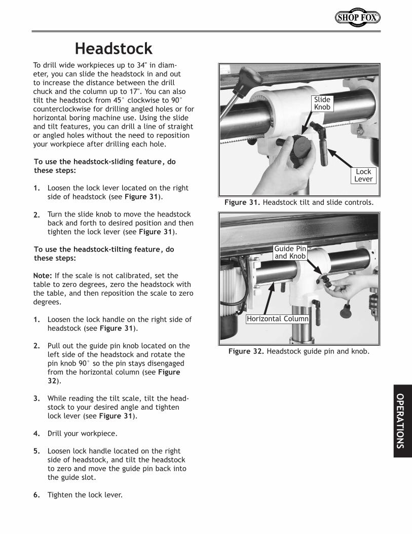
To drill wide workpieces up to 34" in diam-eter, you can slide the headstock in and out to increase the distance between the drill chuck and the column up to 17". You can also tilt the headstock from 45° clockwise to 90° counterclockwise for drilling angled holes or for horizontal boring machine use. Using the slide and tilt features, you can drill a line of straight or angled holes without the need to reposition your workpiece after drilling each hole.
To.use.the.headstock-sliding.feature,.do.these.steps:
1. Loosen the lock lever located on the right side of headstock (see Figure.31).
2.. Turn the slide knob to move the headstock back and forth to desired position and then tighten the lock lever (see Figure.31)..
To.use.the.headstock-tilting.feature,.do.these.steps:
Note: If the scale is not calibrated, set the table to zero degrees, zero the headstock with the table, and then reposition the scale to zero degrees.
1.. Loosen the lock handle on the right side of headstock (see Figure.31).
2.. Pull out the guide pin knob located on the left side of the headstock and rotate the pin knob 90° so the pin stays disengaged from the horizontal column (see Figure.32).
3.. While reading the tilt scale, tilt the head-stock to your desired angle and tighten lock lever (see Figure.31).
4.. Drill your workpiece.
5.. Loosen lock handle located on the right side of headstock, and tilt the headstock to zero and move the guide pin back into the guide slot.
6.. Tighten the lock lever.
Headstock
Figure.31. Headstock tilt and slide controls.
Figure.32..Headstock guide pin and knob.
Lock Lever
Slide Knob
Guide Pin and Knob
Horizontal Column
OPERA
TION
S
-20-
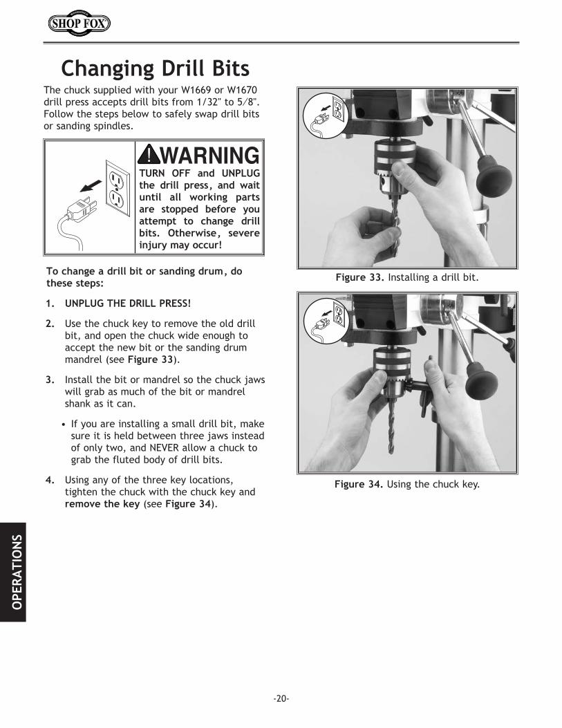
To.change.a.drill.bit.or.sanding.drum,.do.these.steps:
1. UNPLUG.THE.DRILL.PRESS!
2.. Use the chuck key to remove the old drill bit, and open the chuck wide enough to accept the new bit or the sanding drum mandrel (see Figure.33).
3.. Install the bit or mandrel so the chuck jaws will grab as much of the bit or mandrel shank as it can.
• If you are installing a small drill bit, make sure it is held between three jaws instead of only two, and NEVER allow a chuck to grab the fluted body of drill bits.
4.. Using any of the three key locations, tighten the chuck with the chuck key and remove.the.key (see Figure.34).
Figure.34..Using the chuck key.
Figure.33..Installing a drill bit.
TURN. OFF. and. UNPLUG.the. drill. press,. and. wait.until. all. working. parts.are. stopped. before. you.attempt. to. change. drill.bits.. Otherwise,. severe.injury.may.occur!
Changing.Drill.BitsThe chuck supplied with your W1669 or W1670 drill press accepts drill bits from 1/32" to 5⁄8''.Follow the steps below to safely swap drill bits or sanding spindles.
OPE
RATI
ON
S

Speed.Changes
To.change.the.drilling.speed,.do.these.steps: 1... UNPLUG.THE.DRILL.PRESS!
2.. Loosen the belt tension lock knobs on the side of the headstock (see Figure.35).
3. Locate the desired speed on the chart and move the V-belt to the desired V-grooves on the motor and spindle pulleys (see Figure.36).
4.. Push the motor inward, and move the V-belt to the right spot.
5.. Push the motor toward the back of the headstock. The motor support rod is spring loaded and will follow the motor. Tighten the lock knob when the right tension is achieved.
6. Close the cover.
UNPLUG. the. drill. press.before. changing. speeds.to.avoid.accidental.start.up..Failure.to.do.this.may.result.in.serious.personal.injury.
The Model W1669 and W1670 Radial Drill Press has 5 speeds ranging from 550 to 3470 RPM. To find your needed drilling speed and pulley combination, refer to the speed chart located under the belt guard; or go to.Page.22 and refer to the Drill.Press.RPM.Chart.
Figure.35..Loosening lock knob.
Figure.36..Adjusting belt to desired speed.
Never.operate.drill.press.with. belt. cover. in. the.open.position..Your.hand.may.become.trapped.in.a.belt.and.serious.personal.injury.will.occur.
Pushrod
OPERA
TION
S
-21-

Use Figure.37.to select the optimum motor-to-spindle pulley ratio for drilling, cutting, and sanding operations. for example the above figure shows the belt in the C position on the spindle pulley and the #3 position on the motor pulley, which will give a speed of 1,520 RPM. Refer to the Drill,.Cutter,.and.Saw.RPM.Chart on Page.23 for suggested tool RPMs.
Figure.37..Drill Press RPM Chart.
Drill.Press.RPM.Chart
Drilling.DepthYour new drill press comes fitted with a depth stop that allows drilling many holes at a pre-set depth consistently. When the hex nuts are set, the nuts will contact the stop flange and stop the drill press from drilling any deeper.
To.adjust.the.drilling.depth,.do.these.steps:
1. Measure the maximum depth that you want to drill a series of holes at. In this example the maximum depth is 1 1⁄4" deep.
2. Loosen the hex nuts shown on the depth stop and align the lower nut to the 1 1⁄4" mark on the depth stop rod (see Figure.38).
3. Hold the lower hex nut and tighten the upper hex nut so both nuts are locked together.
4. Make sure the depth has been set cor-rectly, measure, or drill a hole into scrap wood before drilling into any workpiece.
Figure.38..Depth stop set for 11⁄4" drilling depth.
Depth..Stop
Upper Hex Nut
Stop.Flange
Lower.Hex.Nut
1-1⁄4"
OPE
RATI
ON
S
-22-

Drill,.Cutter,.and.Hole.Saw.Suggested.RPM.Chart
-23-
.... .... .... .... .... .... ....
.
OPERA
TION
S

-24-
OPE
RATI
ON
S
-25-
Since all bearings are shielded and permanently lubricated, simply leave them alone until they need to be replaced. DO.NOT lubricate them.
For other items on this machine, such as the quill, table and column, horizontal and verti-cal columns, an occasional application of light machine oil is all that is necessary to maintain smooth rust-free operation.
Before applying any lubricant, clean off the old lubricant, and any sawdust or metal chips.
DO.NOT over lubricate, your goal is to achieve adequate lubrication. Too much lubrication will attract dirt and sawdust, and various parts of your machine could loose freedom of move-ment.
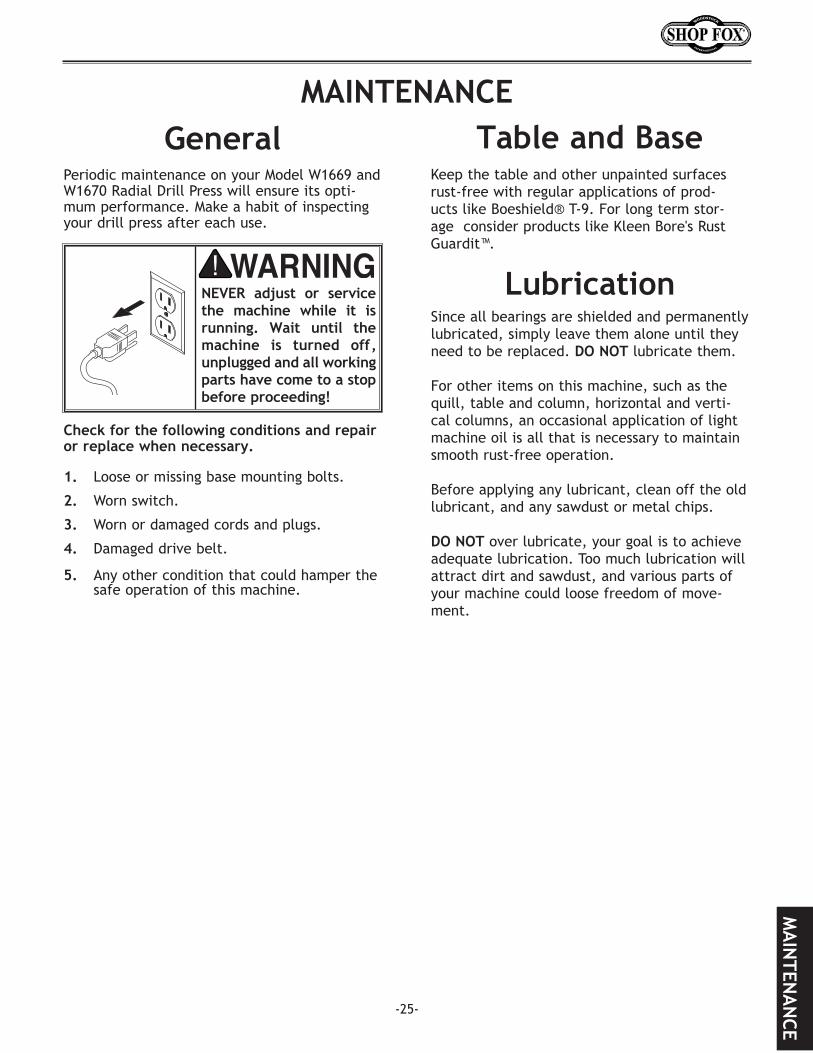
Periodic maintenance on your Model W1669 and W1670 Radial Drill Press will ensure its opti-mum performance. Make a habit of inspecting your drill press after each use.
Check.for.the.following.conditions.and.repair.or.replace.when.necessary.
1. Loose or missing base mounting bolts.
2. Worn switch.
3. Worn or damaged cords and plugs.
4. Damaged drive belt.
5. Any other condition that could hamper the safe operation of this machine.
Keep the table and other unpainted surfaces rust-free with regular applications of prod-ucts like Boeshield® T-9. For long term stor-age consider products like Kleen Bore's Rust Guardit™.
NEVER. adjust. or. service.the. machine. while. it. is.running.. Wait. until. the.machine. is. turned. off,.unplugged.and.all.working.parts.have.come.to.a.stop.before.proceeding!
Table.and.Base
Lubrication
GeneralMAINTENANCE
MA
INTEN
AN
CE
-26-
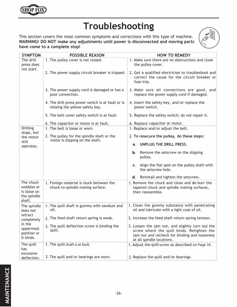
Troubleshooting
MA
INTE
NA
NCE
This section covers the most common symptoms and corrections with this type of machine. WARNING!.DO.NOT.make.any.adjustments.until.power.is.disconnected.and.moving.parts.have.come.to.a.complete.stop!
-27-
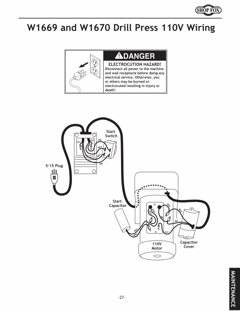
W1669.and.W1670.Drill.Press.110V.Wiring
ELECTROCUTION HAZARD! Disconnect all power to the machine and wall receptacle before doing any electrical service. Otherwise, you or others may be burned or electrocuted resulting in injury or death!
Start Capacitor
Capacitor Cover
110V Motor
Start Switch
Blk
Wht
Wht
Blk
WhtWht
Wht
Blk
Blk
Grn
Grn Grn
5-15 Plug
RedRed
Wht
MA
INTEN
AN
CE
43
47
39 37
51 50
44
48 29
45
59 75
60
32
31
46
27 34
36
28 28A
28
42
41
40
33
20 64
65
66
54
38
53
22
23
93
36
19
56 49 76
53
21
26
62
25
35
52
63
10
77 81
9
30 8
85
86
24
88
87
76
0 1 2 3
15
94
103
79
38�1 89
35�1
19�4
19�1 19�2 19�3
45A�3
45A�1
45A�2
16A�1
16A
11
19�6 19�5
32�1
102
107
105
104
107
106
108
89
33�1
-28-
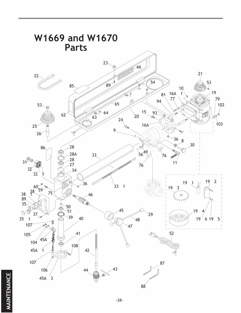
W1669.and.W1670.Parts
MA
INTE
NA
NCE

MA
INTEN
AN
CE
-29-
PARTS.REF. PART.#. .DESCRIPTION
8 X1669008 GEAR9 XPR16M EXT RETAINING RING 9MM10 XPN03M HEX NUT M8-1.2511 X1668019 CLAMP BOLT M10-1.5 X 3015 X1669015 KNOB BOLT M8-1.25 X 1616A X1669016A MOUNT PLATE N/S16A-1 X1669016A-1 MOTOR PLATE N/S19 X1669019 MOTOR 1⁄2 HP, 110V19-1 X1669019-1 S. CAPCTR 150MFD/125VAC19-2 X1669019-2 CAPACITOR COVER19-3 X1669019-3 MOTOR FAN19-4 X1669019-4 FAN COVER19-5 XPS54M PHLP HD SCR M4-.75 X 619-6 XPW05M FLAT WASHER 4MM20 X1669020 PULLEY COVER21 X1669021 MOTOR PULLEY22 X1669022 V-BELT 0-148023 X1669023 UNTHREADED FEMALE KNOB24 X1669024 LOCK PIN ASSEMBLY25 X1669025 SPINDLE PULLEY26 X1669026 DRIVE SLEEVE27 XPR23M INT RETAINING RING M4028 XP6203 BEARING 620328A X1669028A SPACER29 X1669029 KNOB30 X1669030 LEVER31 XPLN08 LOCK NUT 1⁄2"-2032 X1669032 COVER WITH SPRING32-1 X1669032 COVER WITH SPRING33 X1669033 HORIZONTAL COLUMN33-1 X1669033-1 HORIZONTAL COLUMN RACK34 X1669034 HEADSTOCK35 XPSW09 SWITCH AND KEY35-1 XPSW09-1 SWITCH KEY36 XPSS02 SET SCREW 5⁄16"-18 X 3⁄8"37 XPS22 PHLP SCREW 10-24 X 5⁄8"38 X1669038 SWITCH BOX38-1 X1669038-1 SWITCH MOUNTING PLATE39 X1669039 RUBBER WASHER40 X1669040 QUILL SHAFT41 XP6202 BEARING 620242 X1669042 SPINDLE JT#33
.REF. PART.#. .DESCRIPTION
43 X1669043 CHUCK KEY44 X1669044 1⁄2" CHUCK 1-16MM JT#3345 X1668031 COLLAR45A-1 X1668031A DEPTH STOP ROD N/S45A-2 X1669045A-1 DEPTH STOP ROD BRACKET45A-3 X1668031A-6 DEPTH STOP MOUNT46 X1668030 FEED SHAFT47 X1668033 FEED COLLAR48 X1669048 HANDLE49 X1669049 DEGREE SCALE50 XPR03M EXT RETAINING RING 12M51 XP6201 BEARING 620152 X1669052 POWER CORD53 X1669053 SET SCREW54 XPS07 PHLP SCREW 1⁄4"-20 X 3⁄8"56 X1669056 RIVET59 X1669059 SPECL SET SCR 5⁄16"-18 X 1"60 XPN02 HEX NUT 5⁄16"-1862 X1669062 LABEL63 X1669063 WIRE STRAP64 XPS06 PHLP SCREW 10-24 X 3⁄8"65 X1669065 MOTOR SWITCH CORD66 X1669066 SPEED CHART75 X1669075 SAFETY LABEL76 X1669076 LOCKING GIB77 XPW01M FLAT WASHER 8MM79 XPW06M FLAT WASHER 12MM81 XPB09M HEX BOLT M8-1.25 X 2085 X1669085 SAFETY GOGGLES LABEL86 X1669086 LONG HAIR SAFETY LABEL87 XPAW03M HEX WRENCH 3MM88 XPAW05M HEX WRENCH 5MM89 XPHTEK7 SELF TAP SCREW #8 X 3⁄8"93 X1669093 RUBBER WASHER 8MM94 X1669094 GUIDE ROD 16 X 30MM102 XPN02M HEX NUT M10-1.5103 XPLW06M LOCK WASHER 10MM104 XPW03M FLAT WASHER 6MM105 XPS68M PHLP HD SCR M6-1 X 10106 XPN03M HEX NUT M8-1.25 107 XPN02M HEX NUT M10-1.5 108 XPSB14M CAP SCREW M8-1.25 X 20
W1669,.W1670.Parts.List
-30-
1
3
4
5
83
84
7879
71
7374
7� 7�
8�
73
7
����������������
98
93
13
91
99
7��
84�1
5�
11
11
7�1
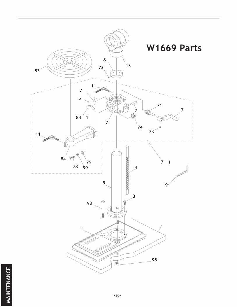
W1669.Parts
MA
INTE
NA
NCE

MA
INTEN
AN
CE-31-
PARTS.REF. PART.#. .DESCRIPTION
1 X1669001 BASE3 XPB09M HEX BOLT M8-1.25 X 204 X1669004 W1669 RACK 5 X1669005 W1669 COLUMN7 X1669007 GEARED TBL BRKT N/S7-1 X1669007-1 COMPLETE TBL BRKT ASSY7-2 X1669007-2 GEARED TBL BRKT SCALE11 X1668019 LEVER BOLT M10-1.5 X 3013 X1669013 HORR. COLUMN BRKT54 XPS07 PHLP SCREW 1⁄4"-20 X 3⁄8"56 X1669056 RIVET70 X1669070 PIN71 X1669071 WORM PINION
.REF. PART.#. .DESCRIPTION
72 X1669072 LIFT HANDLE CRANK73 XPSS01M SET SCREW M6-1.0 X 1074 X1669074 10T GEAR78 XPSB77M CAP SCREW M12-1.75 X 3079 XPW06M FLAT WASHER 12MM80 X1669080 COLUMN RING83 X1669083 TABLE84 X1669084 COLUMN SUPPORT ARM N/S84-1 X1669084-1 SCALE91 XPAW10M HEX WRENCH 10MM93 X1670093 HEX BOLT M8-1.25 X 12599 XPLW05M LOCK WASHER 12MM98 XPWN02M WING NUT M8-1.25
W1669.Parts.List

-32-
1
71
7374
70 72
4A
84
94
95
96
97
11
11
84A
80
73
7
3
����������������
98
93
13
83
5A101
92
56
7�2
84�1
7�1
W1670.Parts
MA
INTE
NA
NCE

MA
INTEN
AN
CE
-33-
PARTS.REF. PART.#. .DESCRIPTION
1 X1670001 BASE3 XPB31M HEX BOLT M10-1.5 X 404A X1670004A W1670 RACK 5A X1670005A W1670 COLUMN7 X1668010A GEARED TBL BRKT N/S7-1 X1668010A-2 COMPLETE TBL BRKT ASSY7-2 X1669007-2 SCALE11 X1668019 LEVER BOLT M10-1.5 X 3013 X1670013 HORR. COLUMN BRKT56 X1669056 RIVET70 X1668010A-3 AXLE71 X1668012 WORM PINION72 X1668016 LIFT HANDLE73 XPSS01M SET SCREW M6-1.0 X 10
.REF. PART.#. .DESCRIPTION
74 X1668015 WORM GEAR80 X1668008 COLUMN RING83 X1670083 TABLE84 X1668010A-1 COLUMN SUPPORT ARM N/S84-1 X1669084-1 SCALE84A X1670084A TABLE SUPPORT ARM92 X1668013 CLAMP BOLT M12-1.75 x 5093 X1670093 HEX BOLT M8-1.25 X 12594 XPN01M HEX NUT M6-1.095 X1668111B SPECIAL PIN96 X1670096 HEX BOLT 5⁄8"-13 X 11⁄2"97 XPW14 FLAT WASHER 5⁄8"98 XPWN02M WING NUT M8-1.25101 X1668152 SPECIAL WRENCH
W1670.Parts.List
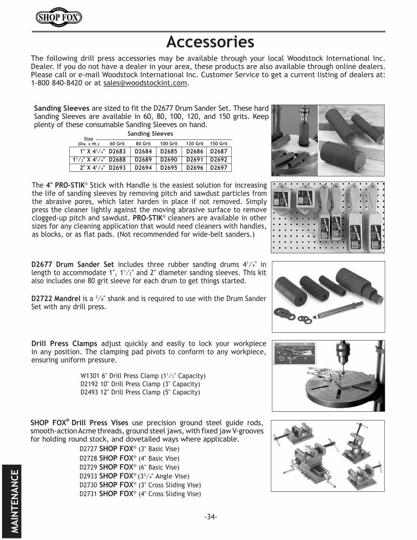
SHOP FOX®.Drill. Press. Vises use precision ground steel guide rods, smooth-action Acme threads, ground steel jaws, with fixed jaw V-grooves for holding round stock, and dovetailed ways where applicable. D2727 SHOP FOX® (3" Basic Vise) D2728 SHOP FOX® (4" Basic Vise) D2729 SHOP FOX® (6" Basic Vise) D2933 SHOP FOX® (33⁄4" Angle Vise) D2730 SHOP FOX® (3" Cross Sliding Vise) D2731 SHOP FOX® (4" Cross Sliding Vise)
The 4".PRO-STIK® Stick with Handle is the easiest solution for increasing the life of sanding sleeves by removing pitch and sawdust particles from the abrasive pores, which later harden in place if not removed. Simply press the cleaner lightly against the moving abrasive surface to remove clogged-up pitch and sawdust. PRO-STIK® cleaners are available in other sizes for any cleaning application that would need cleaners with handles, as blocks, or as flat pads. (Not recommended for wide-belt sanders.)
-34-
The following drill press accessories may be available through your local Woodstock International Inc. Dealer. If you do not have a dealer in your area, these products are also available through online dealers. Please call or e-mail Woodstock International Inc. Customer Service to get a current listing of dealers at: 1-800 840-8420 or at [email protected].
D2677. Drum. Sander. Set includes three rubber sanding drums 41⁄4" in length to accommodate 1", 11⁄2" and 2" diameter sanding sleeves. This kit also includes one 80 grit sleeve for each drum to get things started. D2722.Mandrel is a 3⁄8" shank and is required to use with the Drum Sander Set with any drill press.
Drill. Press. Clamps adjust quickly and easily to lock your workpiece in any position. The clamping pad pivots to conform to any workpiece, ensuring uniform pressure. W1301 6" Drill Press Clamp (11⁄2" Capacity) D2192 10" Drill Press Clamp (3" Capacity) D2493 12" Drill Press Clamp (5" Capacity)
Accessories
Sanding.Sleeves are sized to fit the D2677 Drum Sander Set. These hard Sanding Sleeves are available in 60, 80, 100, 120, and 150 grits. Keep plenty of these consumable Sanding Sleeves on hand.
Sanding.Sleeves. Size.. (Dia..x.Ht.). 60.Grit. 80.Grit.. 100.Grit. 120.Grit. 150.Grit
. 1".X.41⁄4". D2683. D2684. D2685. D2686. D2687
. 11⁄2".X.41⁄4". D2688. D2689. D2690. D2691. D2692
. 2".X.41⁄4". D2693. D2694. D2695. D2696. D2697
MA
INTE
NA
NCE
MA
INTEN
AN
CE
-35-
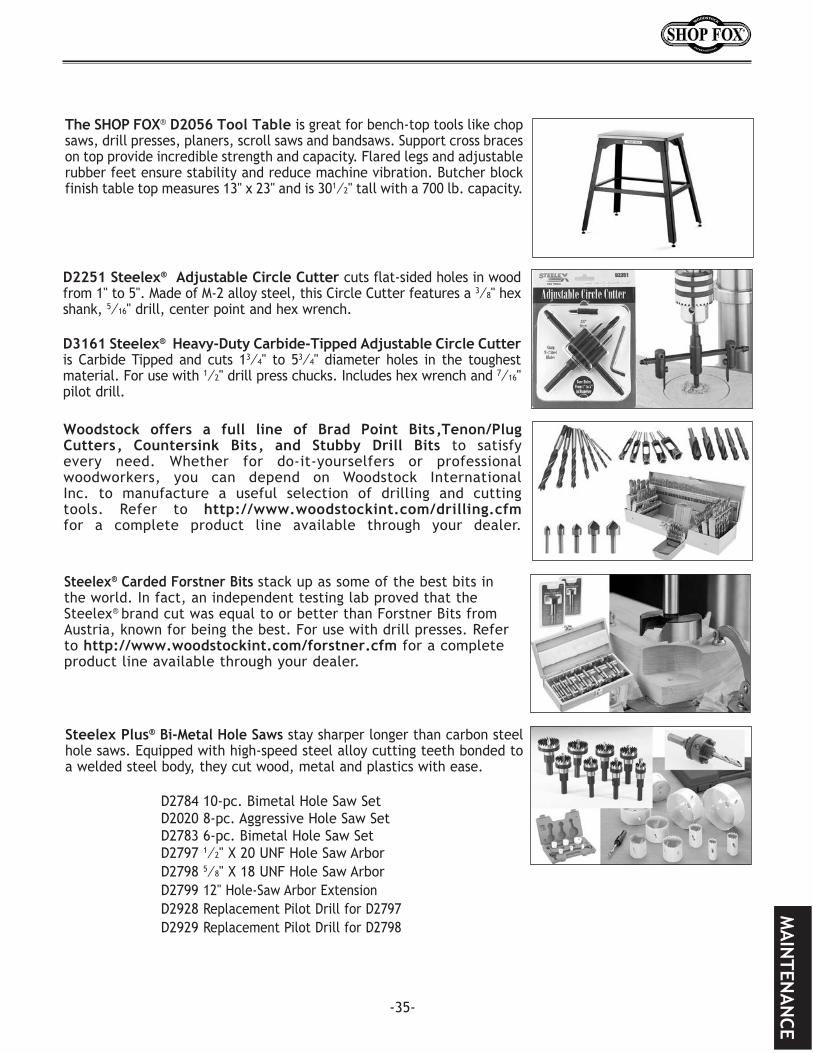
Steelex®.Carded.Forstner.Bits stack up as some of the best bits in the world. In fact, an independent testing lab proved that the Steelex® brand cut was equal to or better than Forstner Bits from Austria, known for being the best. For use with drill presses. Refer to http://www.woodstockint.com/forstner.cfm for a complete product line available through your dealer.
Woodstock. offers. a. full. line. of. Brad. Point. Bits,Tenon/Plug.Cutters,. Countersink. Bits,. and. Stubby. Drill. Bits to satisfy every need. Whether for do-it-yourselfers or professional woodworkers, you can depend on Woodstock International Inc. to manufacture a useful selection of drilling and cutting tools. Refer to http://www.woodstockint.com/drilling.cfm for a complete product line available through your dealer.
D2251.Steelex®..Adjustable.Circle.Cutter cuts flat-sided holes in wood from 1" to 5". Made of M-2 alloy steel, this Circle Cutter features a 3⁄8" hex shank, 5⁄16" drill, center point and hex wrench.
D3161.Steelex®..Heavy-Duty.Carbide-Tipped.Adjustable.Circle.Cutter.is Carbide Tipped and cuts 13⁄4" to 53⁄4" diameter holes in the toughest material. For use with 1⁄2" drill press chucks. Includes hex wrench and 7⁄16" pilot drill.
The.SHOP FOX® D2056.Tool.Table is great for bench-top tools like chop saws, drill presses, planers, scroll saws and bandsaws. Support cross braces on top provide incredible strength and capacity. Flared legs and adjustable rubber feet ensure stability and reduce machine vibration. Butcher block finish table top measures 13" x 23" and is 301⁄2" tall with a 700 lb. capacity.
Steelex.Plus®.Bi-Metal.Hole.Saws stay sharper longer than carbon steel hole saws. Equipped with high-speed steel alloy cutting teeth bonded to a welded steel body, they cut wood, metal and plastics with ease.
D2784 10-pc. Bimetal Hole Saw Set D2020 8-pc. Aggressive Hole Saw Set D2783 6-pc. Bimetal Hole Saw Set D2797 1⁄2" X 20 UNF Hole Saw Arbor D2798 5⁄8" X 18 UNF Hole Saw Arbor D2799 12" Hole-Saw Arbor Extension D2928 Replacement Pilot Drill for D2797 D2929 Replacement Pilot Drill for D2798

-36-
Notes

Notes
-37-

Woodstock International, Inc. warrants all SHOP FOX® machinery to be free of defects from workman-ship and materials for a period of two years from the date of original purchase by the original owner. This warranty does not apply to defects due directly or indirectly to misuse, abuse, negligence or acci-dents, lack of maintenance, or reimbursement of third party expenses incurred.
Woodstock International, Inc. will repair or replace, at its expense and at its option, the SHOP FOX® machine or machine part which in normal use has proven to be defective, provided that the original owner returns the product prepaid to the SHOP FOX® factory service center or authorized repair facil-ity designated by our Bellingham, WA office, with proof of their purchase of the product within two years, and provides Woodstock International, Inc. reasonable opportunity to verify the alleged defect through inspection. If it is determined there is no defect, or that the defect resulted from causes not within the scope of Woodstock International Inc.'s warranty, then the original owner must bear the cost of storing and returning the product.
This is Woodstock International, Inc.'s sole written warranty and any and all warranties that may be implied by law, including any merchantability or fitness, for any particular purpose, are hereby lim-ited to the duration of this written warranty. We do not warrant that SHOP FOX® machinery complies with the provisions of any law or acts. In no event shall Woodstock International, Inc.'s liability under this warranty exceed the purchase price paid for the product, and any legal actions brought against Woodstock International, Inc. shall be tried in the State of Washington, County of Whatcom. We shall in no event be liable for death, injuries to persons or property or for incidental, contingent, special or consequential damages arising from the use of our products.
Every effort has been made to ensure that all SHOP FOX® machinery meets high quality and durabil-ity standards. We reserve the right to change specifications at any time because of our commitment to continuously improve the quality of our products.
Warranty

Name ___________________________________________________________________________________
Street __________________________________________________________________________________
City _________________________ State ___________________________Zip ________________________
Phone # ______________________ E-mail __________________________Invoice # ___________________
Model #_________Serial #______________Dealer Name__________________Purchase Date___________
Warranty.Registration
The following information is given on a voluntary basis. It will be used for marketing purposes to help us develop better products and services. Of course, all information is strictly confidential.
1. How did you learn about us? _____ Advertisement _____ Friend ____ Local Store _____ Mail Order Catalog _____ Website ____ Other:
2. How long have you been a woodworker/metalworker? _____ 0-2 Years _____ 2-8 Years ____ 8-20 Years _____ 20+ Years
3. How many of your machines or tools are Shop Fox®? _____ 0-2 _____ 3-5 ____ 6-9 _____ 10+
4. Do you think your machine represents a good value? _____ Yes ____ No
5. Would you recommend Shop Fox® products to a friend? _____ Yes ____ No
6. What is your age group? _____ 20-29 _____ 30-39 ____ 40-49 _____ 50-59 _____ 60-69 ____ 70+
7. What is your annual household income? _____ $20,000-$29,000 _____ $30,000-$39,000 ____ $40,000-$49,000 _____ $50,000-$59,000 _____ $60,000-$69,000 ____ $70,000+
8. Which of the following magazines do you subscribe to?
9. Comments:.__________________________________________________________________
. _____________________________________________________________________________.
. _____________________________________________________________________________.
. _____________________________________________________________________________.
____ Cabinet Maker____ Family Handyman____ Hand Loader____ Handy____ Home Shop Machinist____ Journal of Light Cont.____ Live Steam____ Model Airplane News____ Modeltec____ Old House Journal
____ Popular Mechanics____ Popular Science____ Popular Woodworking____ Practical Homeowner____ Precision Shooter____ Projects in Metal____ RC Modeler____ Rifle____ Shop Notes____ Shotgun News
____ Today’s Homeowner____ Wood____ Wooden Boat____ Woodshop News____ Woodsmith____ Woodwork____ Woodworker West____ Woodworker’s Journal____ Other:

TAPE ALONG EDGES--PLEASE DO NOT STAPLE
FOLD ALONG DOTTED LINE
FOLD ALONG DOTTED LINE
WOODSTOCK.INTERNATIONAL,.INC.P.O..BOX.2309BELLINGHAM,.WA..98227-2309
PlaceStampHere


![[Theodore Sider] Logic for Philosophy](https://img.pdfslide.us/doc/110x75/54526e14b1af9f7f248b50d7/theodore-sider-logic-for-philosophy.jpg)