Embed Size (px)
Citation preview

Instruction Manual
Instructions and model
prototype prepared by
Chuck Passaro
Kit No. MS1458
Scale: 1/2” = 1 ft.
Overall Length: 11 ¾”
Height: 2 ½”
Made in the USA with Pride by
Model Shipways
A division of Model Expo
WWW.MODELEXPO-ONLINE.COM
Copyright Model Expo 2012
ENGLISH
PINNACE (Circa 1750-1760)

Having recently designed the Model Shipways
kit for an 18th century longboat, I wanted to
follow up that project with something that
would complement it. I wanted to create
another small boat from the period, as I find very
enjoyable to build. Searching for inspiration, I
came across some models for 18th century
pinnaces. There were large 32 foot pinnaces
and many smaller examples to look at. I was
particularly fond of one model from the NMM
in Greenwich. It was a model of a 21 foot long
single banked pinnace from around 1750. It
would make an excellent subject for this new
project. It has a paneled interior and some
decorative merits. I found an original draft that
was almost identical to this small 4-oared
pinnace. Things were starting to come together
nicely. I recommend that all of you browse the
National Maritime Museum (Greenwich)
website. There are thousands of photos of
contemporary models as well as the original
drafts for them. The website is www.rmg.co.uk.
I wasn’t necessarily thrilled with the color
scheme shown on this model (pictured above), so I continued looking for some decorative
alternatives. The pinnace was used as a means
of transport for a ship’s captain or other
officers. It was not intended to be used to
perform any other task. Tasks such as
transporting water and other stores were
normally left for the larger and heavier built
boats like the longboat or launch. It was
basically an officers' private transport. It was
designed to be rowed although larger pinnaces
could be sailed. It wasn’t very seaworthy and
was designed for primarily shore duties. After
all, the officers needed a stylish way to get from
their anchored ship to the dockyard. As such,
the decorations were usually added much later
at the officer’s and captain’s own expense.
The pinnace was almost indistinguishable from
what were called barges during this same time
period. These were lightly built, carvel planked
boats designed for rowing as well. The pinnace
and the barge were very long boats in
comparison to their beam. What determined
their designation was merely the number of
oars. Any boat with these distinct
characteristics with more than ten oarsmen
was called a barge, while those designed with
fewer were referred to as a pinnace.
So I searched for more models of either a
pinnace or a barge that was more appealing to
me as far as the painting and decorations were
concerned. I wasn’t looking for anything that
was too elaborate, as the smaller pinnaces were
rarely as richly decorated as the larger admiral’s
barge. I managed to find several other models
that appealed to me. I decided to take a few
decorative elements from each and add them
to the smaller 21’ pinnace for this kit. I was
much more satisfied with simple red panels
inboard and painted frieze outboard on this
model.
It didn’t take too long before I had a working set
of plans that contained all of the parts for this
model. At ¼” scale, a model of a 21 foot
pinnace is not even 6" long. This would
be very finicky to put together, so I decided to
double its size. I have scaled it up to ½” which
should allow for more detail as well.
A model of a 21 foot pinnace from around
1750 that became the inspiration for this
project.

I think it will be an interesting and fun kit to
build and shouldn’t take longer than just a few
weeks to finish.
Getting Started…
To begin, examine the laser cut basswood
sheets for the bulkheads and keel parts. You
will notice that there is some laser char on both
sides of each sheet. There will be a lot more
laser burning on one side vs. the other. This is
because the side that faces down on the laser
cutter usually receives more burning than the
other side. Before you remove any of the parts
from either sheet, sand both sides of each sheet
smooth with some 320 grit sandpaper to
remove this laser char. It is easier to do so now
than after you cut them free from the sheet.
Remove the slotted false keel from the
basswood sheet. Then carefully remove the
stem and keel strip from the 1/8” sheet as well.
Sand the laser char from the edges of each
piece. It isn’t necessary to do this for each slot
in the false keel. In fact, it’s probably better not
to sand the slots yet. You don’t want to enlarge
these slots so the bulkhead frames would be
loose. This kit was actually designed so the
frames would fit snugly into each slot. In fact,
they probably will not fit yet, as you will need to
adjust the notches in each bulkhead and its
corresponding slot on the false keel individually
later. These adjustments should be left until it is
time to dry fit them one at a time later. Right
now we will concentrate on preparing the false
keel properly so you can attach the stem and
keel.
You will notice in the photo provided that the
bearding line has been laser-etched onto one
side of the false keel. This detail should be
transferred to the other side of the false keel
using the plans. It would be very difficult to
build a small model like this in the exact same
way that the full sized pinnace was built in the
18th century. But it is still very important that
some of the construction features are designed
into the model. It would be very difficult to
properly plank the boat if the keel is not
tapered at the stern. You will need to gradually
taper the false keel from the bearding line
towards the outside edges.
This piece is only 1/8” thick but it will be
necessary to gradually reduce its thickness
along the edges of the false keel. It should be
reduced to slightly LESS than1/16” thick. I
realize that this sounds incredibly difficult and
you would think that it would become too
fragile. But that will not be the case. This is
crucial in order to have the planking sit flush
against the keel and stern post. If the false keel
isn’t reduced in thickness, the planking will
actually stand proud of the keel and stern post
which would look just awful. You should taper
the area from the bearding line as shown. Sand
or file it so it gradually reduces in thickness
from that line to the edge. Then carry that
bearding line forward along the bottom of the
keel and up the stem at the bow. The hull
planking will sit in this rabbet which will be
formed once the keel and stem are glued into
position.
One good trick that you will help you bevel the
edges of the false keel: Run a length of 1/16”
wide pinstripe tape down the bottom edge of
the false keel and up the stem and stern post.
Be careful to center it so you have 1/32” on
each side of the tape. A dark color tape is
easier to use so you can see it better. Now you
can sand or file that bevel from the bearding
line to the edge of the tape. This will make it
easier to get a really neat and consistent bevel
along its entire length. In the photo provided
above, you can see that I used black pinstripe
tape. Once you pull off the tape it will reveal
quite a straight edge.
Once the false keel is tapered on both sides as
described, you can glue the keel and stem into
position. Be careful to center the keel along the
bottom of the false keel. This will create a
consistent rabbet for the planking. Allow the
basswood keel to run beyond the aft end of the
false keel. You will trim it to the proper length
later after the planking and stern post are added.
Adding the Bulkhead-Frames…
The bulkheads were designed in basswood for a
specific reason. The softer wood will allow you
to snap the center tab of each bulkhead to
remove it after the planking is completed.
Once the center tabs of all bulkheads are
removed, it will leave the outer frames intact
and simulate an actual framed appearance. To
do this, the wood grain actually runs across
each bulkhead. This makes is easier to snap the
center tabs free to remove them. Do not
remove the center tabs of any bulkhead until
after you plank the hull.
There are 24 laser cut bulkheads for this model.
They are 1/16” thick. They should be glued into
their respective notches along the false keel.
THIS IS WORTH REPEATING: Make sure you
leave the center of each bulkhead intact when
you glue them into position. The center of each
bulkhead is held in place with three small tabs,
one on the bottom and one on each side of the
top of each bulkhead. Test each bulkhead to
see if it will fit into each notch of the false keel
properly. They shouldn’t be loose and they

shouldn’t be too tight. They should be a snug
fit. If you think they fit too tightly, a little filing
of each notch will do the trick. This will
absolutely be needed. Take your time tweaking
those notches. Dry fit all of the bulkheads
before you glue them into position.
As you are adding the bulkheads, make sure
you view each of them from the bow and stern
“head-on”. Look down the keel to make sure
they are all centered and lined up correctly. This
is a tricky and important step. You should have
enough time before the glue dries to make sure
that a bulkhead isn’t leaning crooked to one
side. You can draw a reference line down the
center of each bulkhead if it will help you keep
them all lined up with keel properly. The flat
tops of the bulkhead centers are another good
focal point for observation. They should all be
straight and consistent with one another as you
glue more of them into position. This is
important as the hull will not be faired properly
if they are not lined up. You should view the
bulkheads from above to make sure they are
glued in at a right angle to the keel and spaced
evenly apart as well. You might consider using
yellow wood glue for this because the open
time is longer. This will give you more time to
make adjustments before the glue sets
permanently.
Fairing the hull is the process of sanding the
outside of the hull carefully. You must sand the
outside of the bulkheads so the planking will lay
flat against each edge. Use 220 grit sand paper
or finer. The basswood is soft and will sand
easily. Don’t use a lot of pressure. Use a light
touch because the bulkheads are delicate and
they will move and bend as you work. Take
your time here. Some builders like to glue a
strip or two of wood across the tops of the
bulkheads to secure them better (from bow to
stern). This will stop them from moving and
bending as you fair the hull. If you do this, the
strips will need to be removed before you can
cut the centers of each bulkhead free later on.
So do not use too much glue and make sure the
strips can be easily removed.
After the hull is faired, you can add the transom
(1/16” thick -photo provided left). This piece
was added after the hull was faired because it is
only glued to the edge of the false keel. It might
split or break off otherwise. It is only 1/16”
thick but still needs to be faired with the

bulkheads. Please use a very light touch.
Carefully glue it to the back edge of the false
keel. There is a small notch to help you line it up
correctly. Just sit the bottom of the transom on
top of the notch. Make sure it is straight and at
a right angle to the keel before the glue dries.
Drawing a line down the center of the transom
should help you line it up with the edge of the
false keel.
At the bow, there are two basswood filler
pieces that will help make the hull planking
easier (photo above). These 1/16” thick pie-
shaped pieces should be glued to the sides of
the false keel at the bow. A photo is provided
that shows these two pieces glued into position
along with the transom. Fair the two bow fillers
to get a smooth run of your planks onto that
first bulkhead. It’s a tight area to work in but
this is essential if you want to create the correct
shape of the bow while planking. Pay close
attention to the front edge of the filler pieces at
the bow. It should have a 1/32” wide space
between it and the laser cut stem stem. This
space should be consistent along the length of
the stem. See the detail photo on the previous
page. Your planking will be inserted into this
rabbet at the bow and give you a nice clean
appearance.
Planking the Pinnace…
The hull will be planked using 3/16” x 1/32”
basswood strips. It will accommodate 10
strakes on each side, although there may be a
need to use a wider strake to complete the
planking effectively. Some ¼” wide planking
strips are included for this purpose. What
follows is a description of how I planked my
prototype for this kit.
Some might argue that the only way to properly
plank a small boat like this would be to spile
each plank individually. Because it is presented
as a kit, most folks are accustomed to receiving
pre-milled strips for their planking. It is indeed
very possible to plank a small hull like this using
pre-milled strips. It will just require that each
strip be pre-bent to the proper shape and
possibly tapered to get the job done.
I dip my planks in a glass of water for about 10
seconds. Then I clamp them to various jigs and
shapes in order to mold them. While they are
clamped into the shape required, I quickly dry
them using an old blow dryer. The hair dryer is
turned up to its hottest setting and used to heat
up the planking strip. In just a minute or two,
the strip is completely dry. I will give it another
minute to cool down before it is removed
from the jig. Each strip should hold its shape
well with minimal spring-back.
The basswood strips can be clamped around a
bottle cap as shown, or clamped to a flat
surface to achieve an edge-wise bend (photos
on top of next page). Both types of bending will
be required in order to properly shape each
strake so it will lie flat against each bulkhead
frame. You could, however, spile the shape for
each plank and cut it from a wider sheet of
1/32” basswood, if you prefer. There are many
books available on the topic and making this a
treatise on planking is beyond the scope of
these instructions. One such book is “Planking
the Built- Up Ship Model” by Jim Roberts. It is
available from Model Expo.
To begin, glue one strake along the sheer of the
hull. This first strake should extend well past
the transom at the stern. The decorative cast
“second-transom” will be glued directly to the
ends of these two planks. Examine the plans to
determine how long this first plank should
extend past the transom.
Immediately below this sheer strake, glue
another. This one will not extend beyond the
transom. I simulated the caulking between
each strake using a soft #2 pencil. I ran it down
one edge of each seam. Each strake was glued
to the hull in one length from bow to stern.
These two initial strakes of planking are very
important. You will see how strong the hull
becomes after they are completed. Make sure
you use plenty of glue to secure these strakes to
each and every frame. You must create a
strong bond for them. It will help immensely
when trying to remove the bulkhead centers
later. If they are not glued to each frame
securely, the thin and fragile framing might split
as you try and cut through the tabs on each side
holding them in place.
Then I began planking the hull from the keel
upwards. I added two strakes against the keel.
The first strake (the garboard) has quite a twist
in it as it progresses towards the stern. One
edge of the garboard strake was beveled so I
could fit it into the rabbet. By sliding it in the
rabbet between the keel and false keel, you can
produce a really clean and neat corner with no
gaps or spaces. Each strip was allowed to
extend past the stern post. I filed them neatly
flush against the false keel afterwards. Examine
the photos on this page which show the
planking process progressing.

I progressed with the planking by adding two more
planks under the sheer and then alternated
again by adding two more working up from the
keel. By planking in this manner, I was able to
meet in the middle. Note in the photo below
how each plank was pre-shaped as described
earlier. You can see the pre-formed curve for
the bow and the twist of the plank needed for
the stern. As you start to close up the hull, you
will finally reach the point where only one
strake remains to be added. This space will not
be consistent at all. In all probability, it will be
wider than 3/16” (especially at mid-ship). A
wider 1/4” x 1/32” strip is provided in the kit for
this purpose. Carefully shape this final plank to
fit the opening on your hull. Because it is in the
middle of the hull where it begins curving
towards the keel, the wider plank won’t be
noticeable when viewing the model from port
or starboard.
Sand the hull smooth and apply a finish. I used
some MinWax Wipe-on Poly. I have posted a
few photos of the hull to show the planking
completed. Please note that the stern post was
also added at this time. The planks were filed
flush against the false keel. Then the laser cut
stern post was glued into position. The keel
was then cut flush to the aft edge of the stern
post to finish it off.
Removing the Frame Tab Centers…
I realize that it can be a bit worrisome when it
comes time to remove the bulkhead centers.
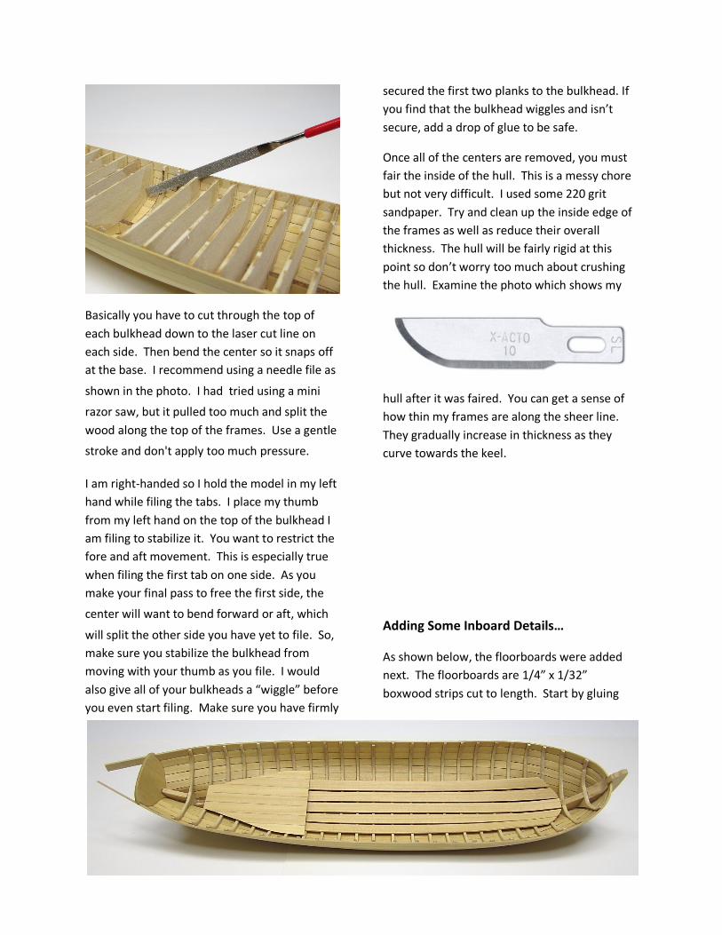
Basically you have to cut through the top of
each bulkhead down to the laser cut line on
each side. Then bend the center so it snaps off
at the base. I recommend using a needle file as
shown in the photo. I had tried using a mini
razor saw, but it pulled too much and split the
wood along the top of the frames. Use a gentle
stroke and don't apply too much pressure.
I am right-handed so I hold the model in my left
hand while filing the tabs. I place my thumb
from my left hand on the top of the bulkhead I
am filing to stabilize it. You want to restrict the
fore and aft movement. This is especially true
when filing the first tab on one side. As you
make your final pass to free the first side, the
center will want to bend forward or aft, which
will split the other side you have yet to file. So, make sure you stabilize the bulkhead from
moving with your thumb as you file. I would
also give all of your bulkheads a “wiggle” before
you even start filing. Make sure you have firmly
secured the first two planks to the bulkhead. If
you find that the bulkhead wiggles and isn’t
secure, add a drop of glue to be safe.
Once all of the centers are removed, you must
fair the inside of the hull. This is a messy chore
but not very difficult. I used some 220 grit
sandpaper. Try and clean up the inside edge of
the frames as well as reduce their overall
thickness. The hull will be fairly rigid at this
point so don’t worry too much about crushing
the hull. Examine the photo which shows my
hull after it was faired. You can get a sense of
how thin my frames are along the sheer line.
They gradually increase in thickness as they
curve towards the keel.
Adding Some Inboard Details…
As shown below, the floorboards were added
next. The floorboards are 1/4” x 1/32”
boxwood strips cut to length. Start by gluing
one down the center of the false keel. Then
add two on each side of that initial strip.
The aft platform was made by gluing 7 small
strips of 1/4” x 1/32” strips together edgewise.
I simulated the caulking between the seams
using a #2 pencil. I created a paper template
from the plans to test the shape of the platform
as drafted. I recommend you do the same. I
placed the paper template in the boat to test
how well it fit. I tweaked that paper template
until I was satisfied. The goal here is to make
sure the platform will sit as low in the hull as
possible, and just above the floorboards. Then I
traced my paper template onto the wood I
glued together. Cut out your platform and glue
it into position.
Installing the Risers…
The risers are long strakes that are nailed to the
inside of the hull. The seats (thwarts) sit on top
of these strakes. They run almost the entire
length of the hull. These two boards are one of
the most important parts of this model. Poorly
placed risers will affect many of the future
parts of the project. Use 1/32” x 3/16”
basswood strips for the risers.
The importance has to do with the position of
the risers. They must be placed an equal
distance from the sheer line. They must also
NOT be placed too high on each side or you
won’t have enough room to create the panels
above them. Examine the plans carefully before
you glue these into position. As a guide, use the
external planking to help you establish the run
for these strips. They should be positioned
along the third exterior planking strip. Use this
as your reference. In fact, the risers might even
be placed just a hair lower (about 1/64”) but
following the run of that third exterior plank. I
have posted a photo of my model above.
You will notice that I placed my risers just a little
bit too high in relation to the third exterior
plank. Unfortunately I didn’t realize it until it
was too late. This will make life somewhat
more difficult when it comes time to create
those panels. I placed mine about 1/32” too
high. My panels will now have to be slightly
narrower when I get to that stage of
construction.
I painted the risers red after they were
installed. I didn’t bother with trying to paint the
underside of each riser since it won’t be seen.
But painting them will be a lot tougher once the
thwarts are installed. These strips should be
pre-bent to shape just like the outside planking
was. Carefully align both risers port-to-
starboard so they are the same distance from
the sheer line. Otherwise your seats (thwarts)
will be crooked and uneven.

Adding the Thwarts and Cockpit Seats…
The first thing I added at this stage was the
seatback for the cockpit area. This can be a
tricky piece to add. The back of the seat has
been laser cut for you and is 1/16” thick. It will
not fit properly after you remove it from the
sheet. The shape is only approximated.
Depending and how you faired the interior and
at what height you placed the risers, there will
be too many variables from model-to model to
laser cut them perfectly.
My solution was to pop the laser cut seatback
from the sheet and trace it onto some card
stock. I used the card stock template as my
working pattern. I tested it on the model. Try
and establish the correct angle when testing
your card stock template. The seatback reclines
as shown on the draft. Slowly and carefully
tweak your template so your seatback fits over
the risers. It should fit snugly against the side of the
hull above the risers too, which means you will
have to notch your template accordingly.
Once you are satisfied, place the template over
your laser cut piece and trace its refined shape.
File and sand your seatback to match the card
stock template and glue it into position. See
the photo of my seatback and its shape prior to
being installed below.
Bypassing the cockpit seats for now, I added the
five thwarts first. The thwarts sit on top of the
risers as I mentioned earlier. The thwarts are
made by cutting a 5/16” x 1/16” strip to the
lengths needed. They were glued into position
and evenly spaced as shown on the plans.
Forward of the first thwart, there is a small
platform. Before gluing this thwart into place at
the bow, I created the platform first.
The platform was made by gluing three small
lengths of 5/16” x 1/16” boxwood strips
together edge-wise. No need to simulate the
caulking this time since the platform will be
painted. I created a card template to create the
shape for the platform just like I discussed for
other aspects of the build earlier. Once I was
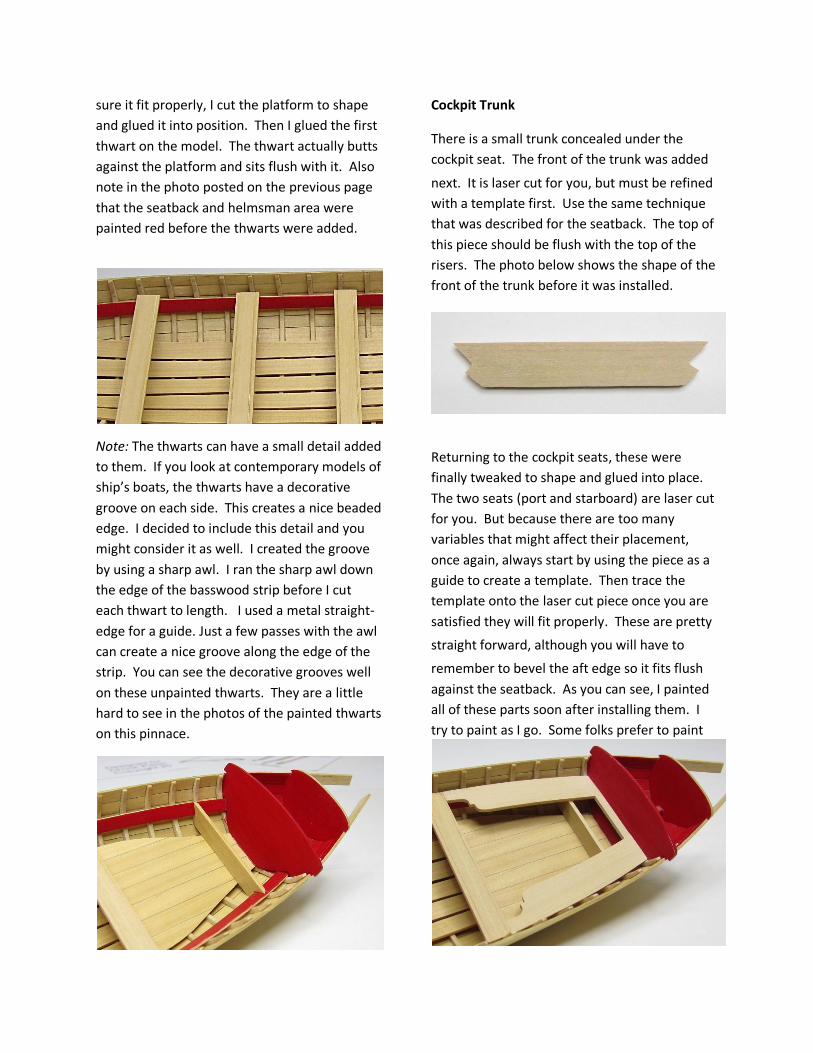
sure it fit properly, I cut the platform to shape
and glued it into position. Then I glued the first
thwart on the model. The thwart actually butts
against the platform and sits flush with it. Also
note in the photo posted on the previous page
that the seatback and helmsman area were
painted red before the thwarts were added.
Note: The thwarts can have a small detail added
to them. If you look at contemporary models of
ship’s boats, the thwarts have a decorative
groove on each side. This creates a nice beaded
edge. I decided to include this detail and you
might consider it as well. I created the groove
by using a sharp awl. I ran the sharp awl down
the edge of the basswood strip before I cut
each thwart to length. I used a metal straight-
edge for a guide. Just a few passes with the awl
can create a nice groove along the edge of the
strip. You can see the decorative grooves well
on these unpainted thwarts. They are a little
hard to see in the photos of the painted thwarts
on this pinnace.
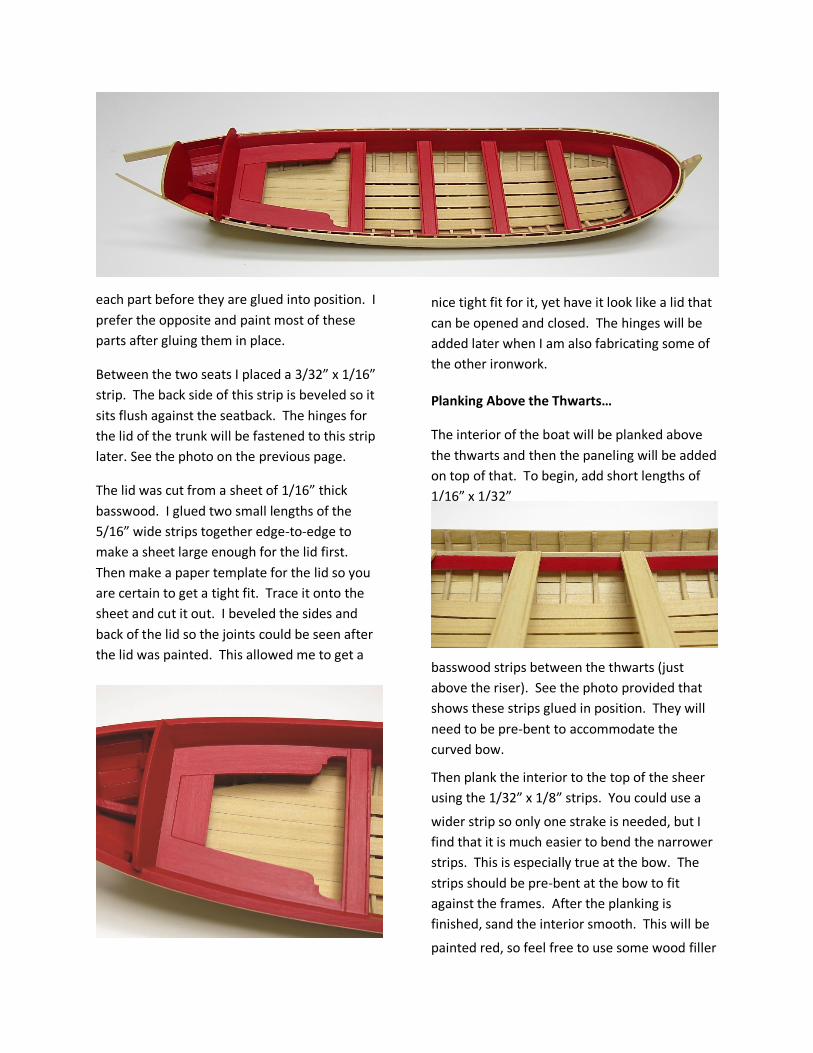
Cockpit Trunk
There is a small trunk concealed under the
cockpit seat. The front of the trunk was added
next. It is laser cut for you, but must be refined
with a template first. Use the same technique
that was described for the seatback. The top of
this piece should be flush with the top of the
risers. The photo below shows the shape of the
front of the trunk before it was installed.
Returning to the cockpit seats, these were
finally tweaked to shape and glued into place.
The two seats (port and starboard) are laser cut
for you. But because there are too many
variables that might affect their placement,
once again, always start by using the piece as a
guide to create a template. Then trace the
template onto the laser cut piece once you are
satisfied they will fit properly. These are pretty
straight forward, although you will have to
remember to bevel the aft edge so it fits flush
against the seatback. As you can see, I painted
all of these parts soon after installing them. I
try to paint as I go. Some folks prefer to paint
each part before they are glued into position. I
prefer the opposite and paint most of these
parts after gluing them in place.
Between the two seats I placed a 3/32” x 1/16”
strip. The back side of this strip is beveled so it
sits flush against the seatback. The hinges for
the lid of the trunk will be fastened to this strip
later. See the photo on the previous page.
The lid was cut from a sheet of 1/16” thick
basswood. I glued two small lengths of the
5/16” wide strips together edge-to-edge to
make a sheet large enough for the lid first.
Then make a paper template for the lid so you
are certain to get a tight fit. Trace it onto the
sheet and cut it out. I beveled the sides and
back of the lid so the joints could be seen after
the lid was painted. This allowed me to get a
nice tight fit for it, yet have it look like a lid that
can be opened and closed. The hinges will be
added later when I am also fabricating some of
the other ironwork.
Planking Above the Thwarts…
The interior of the boat will be planked above
the thwarts and then the paneling will be added
on top of that. To begin, add short lengths of
1/16” x 1/32”
basswood strips between the thwarts (just
above the riser). See the photo provided that
shows these strips glued in position. They will
need to be pre-bent to accommodate the
curved bow.
Then plank the interior to the top of the sheer
using the 1/32” x 1/8” strips. You could use a
wider strip so only one strake is needed, but I
find that it is much easier to bend the narrower
strips. This is especially true at the bow. The
strips should be pre-bent at the bow to fit
against the frames. After the planking is
finished, sand the interior smooth. This will be
painted red, so feel free to use some wood filler
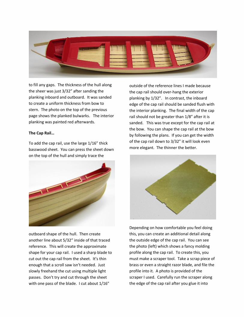
to fill any gaps. The thickness of the hull along
the sheer was just 3/32” after sanding the
planking inboard and outboard. It was sanded
to create a uniform thickness from bow to
stern. The photo on the top of the previous
page shows the planked bulwarks. The interior
planking was painted red afterwards.
The Cap Rail…
To add the cap rail, use the large 1/16” thick
basswood sheet. You can press the sheet down
on the top of the hull and simply trace the
outboard shape of the hull. Then create
another line about 5/32” inside of that traced
reference. This will create the approximate
shape for your cap rail. I used a sharp blade to
cut out the cap rail from the sheet. It’s thin
enough that a scroll saw isn’t needed. Just
slowly freehand the cut using multiple light
passes. Don’t try and cut through the sheet
with one pass of the blade. I cut about 1/16”
outside of the reference lines I made because
the cap rail should over-hang the exterior
planking by 1/32”. In contrast, the inboard
edge of the cap rail should be sanded flush with
the interior planking. The final width of the cap
rail should not be greater than 1/8” after it is
sanded. This was true except for the cap rail at
the bow. You can shape the cap rail at the bow
by following the plans. If you can get the width
of the cap rail down to 3/32” it will look even
more elegant. The thinner the better.
Depending on how comfortable you feel doing
this, you can create an additional detail along
the outside edge of the cap rail. You can see
the photo (left) which shows a fancy molding
profile along the cap rail. To create this, you
must make a scraper tool. Take a scrap piece of
brass or even a straight razor blade, and file the
profile into it. A photo is provided of the
scraper I used. Carefully run the scraper along
the edge of the cap rail after you glue it into

place. Use light passes at first and then several
heavier passes as the profile develops. It will
take many passes along the edge to develop the
fancy edge. Take your time here. If, for
whatever reason, the cap rail doesn’t look right
or the wood becomes damaged, just pop off the
cap rail and replace it.
Adding the Interior Panels…
As you can see from the photos, I painted the
bulwarks red before adding the panels. You
don’t have to do the same. There are pros and
cons to either approach. If you paint the
bulwarks ahead of time, you increase the risk
that you will scuff up and mar the painted
surface. Paint it after the panels are added, and you will need to carefully paint around each
thin strip. This is a tricky decision.
The panels are made using thin strips of
basswood. The kit is supplied with 1/32” x
1/16” strips for this detail.
I started by adding the bottom of each panel
between the thwarts. I used watered down yellow
carpenter’s glue to adhere them to the bulwarks.
Once in position, I cleaned up any excess glue
that squeezed out with a small paint brush dipped
in water. The corners of each panel were mitered.
The sides of each panel were added next.
These are tiny pieces. The tops of these were
spaced 1/16” below the top of the cap rail. To
finish off each square panel, the horizontal top
strip was then glued into position. As you can
see from the photo and the plans, the panels
are 1/16” below the top of the cap rail when
completed. At the bow, only the bottom and
sides where added at this time. Those panels
will be completed after the knee is added at
the bow.
As an added detail, the strips can be scraped
with your “scraper tool” for these as well. Pre-scrape a longer strip. These strips should be
rounded off at a minimum, should you decide
not to create the fancy molding profile. The
strips should be very thin with rounded edges.
They should not appear too heavy or the entire
model will look clunky and less elegant.
Adding the Remaining Inboard Details…
To finish off the interior details, several knees
are added. The photo on the next page shows

three small knees on each side of the hull. They
are placed on top of the thwarts as shown on
the plans and against the bulwarks. These six
knees are optional. I have seen quite a few
contemporary models that show a pinnace with
them and also without them. They were cut
from some scrap lengths of 1/16” x 1/4” strips
and shaped as shown. These details were not
painted in the photos so they would be easier
to see. The decision to paint them is entirely up
to you.
At the bow, you can see the larger knee in
position. I made a paper template using the
plans as a guide. The template was tweaked
until it fit on my model. Then I used it to cut
the knee from the remnants of the 1/16” sheet
of basswood supplied. It was placed 1/16”
below the top of the cap rail. Once glued into
position, the panels at the bow were completed
by adding a tiny pre-bent strip to fill in the area
between the knee and the side of the panels.
The photo above also shows the stanchions
which were positioned under the center of each
thwart. 1/16” x 1/16” strips were used for the
stanchions. They were cut to length and glued
into place. Carefully center them under the
thwarts.
Should you decide to, these stanchions can be
embellished by turning them. They can be
turned by chocking them in a drill or rotary tool
and filing them to shape. Use various needle
files to create a fancy turned column.
Examine the plans and photos provided and you
will notice a small step in the cockpit area.
Abaft of that last thwart is a step down into the
cockpit. I guess the pampered officers couldn’t
handle the steep 14” step and required a more
gradual and easier way to enter the cockpit.
It does add a nice detail to the model, however.
The parts for the step are laser cut for you and
are 1/16” thick. They will, in all likelihood,
require some tweaking to fit your model. There
are many variables that could affect a proper
fit. Depending on how high you placed your
thwarts and how low you placed the cockpit
platform, you will most likely have to adjust the
height of the step. I would also shorten the
length of the step to suit after you determine
the proper height for your model. I assembled
the step completely while it was off the model

and then installed the final assembly. Before I
glued the three pieces to make the step
assembly, I decided to sand them down to
reduce their thickness slightly. This will give the
step a more scaled appearance. I just rubbed
each piece on the top of some 320 grit
sandpaper. This also helped clean up the rough
surface for painting or finishing. On my model, I
decided to leave the step natural rather than
paint it.
The three pieces that create the seats for the
helmsman were shaped using the plans as a
guide. They were cut from the remnants of the
1/16” thick basswood sheet. These three pieces
are pretty straight forward to create. The two
side seats should be cut a little longer, so you
can periodically test them for a snug fit against
the cockpit seat-back and the transom. The
ends for these two pieces are beveled to sit
flush against them. Then I added the center
section against the transom to finish it off. The
aft edge of this piece was also beveled to sit
flush against the inboard side of the transom.
These seats and the knee at the bow were
painted red, but you can pick another color
scheme, should you prefer something different.
The hinges for the cockpit trunk were also
added. I simply used a small square of heavy
card stock for the base. These were glued into
position. On top of these, I centered a length of
22 gauge black wire to simulate the hinge pins.
To add even more detail, I simulated the bolts
on either side of the bin. For these, I drilled some
holes through the paper first and through the
trunk lid. I inserted a small length of 22 gauge
wire in each hole. Then I snipped off the excess
while leaving the wires stand proud of the
paper just a little bit. This does a pretty good
job of simulating a bolt. They were touched up
with black paint afterwards.
To finish off the inboard details, there are three
ringbolts which need to be created. Examine
the plans to find the locations for them. These
were made using the 22 gauge black wire
supplied with the kit. There are two positioned

along the center floorboard and another on top
of the knee at the bow. A photo is provided
that shows the ringbolts before they were glued
into pre-drilled holes. Take a small length of 28
gauge wire and bend it around the ring as
shown. Use a needle-nose plier to crimp the
wire onto itself. Then cut the two lengths which
form the pin on an angle to create a pointed
pin. This should be inserted into the pre-drilled
hole. Some model builders will use an eyebolt
and place the ring in the eye of the eyebolt.
This looks out of scale and shouldn’t be the
method used. Simply crimping a length of wire
tightly around the ring will create a more
historically accurate assembly that looks to
scale.
Outboard Detailing….
It is time to shift our attention outboard. I
added the friezes just below the cap rail. These
are printed sheets that were created on an
inkjet printer. Before you cut them out, it
would be a good idea to apply some sort of
fixative. One approach that is effective without
having to go out and buy some artist’s spray
fixative would be to use some hairspray. This is
an old and cheap trick used by starving artists
to preserve their work. The UV protection also
prevents the colors from fading over time.
The frieze is just 1/8” wide. Carefully cut it out
using a sharp blade. Some extras were
provided just in case. There are two colors to
choose from. The red friezes may be too much
of the same color for some, so another set in
blue was also included. I glued them to the hull
with a child’s glue stick. I have three kids who
use them a lot and I find they work well for
gluing paper onto wood. Apply the glue to the
back of the frieze strip and position it below the
cap rail.
Just below the frieze, add a strip of 1/16” x
1/32” basswood as a molding. You can use the
edge of the frieze strip as a “stop” and guide
while you are gluing it into place. I did run
some sandpaper down the strip to reduce its
thickness slightly. It wasn’t much, but I prefer a
more elegant look, so I try hard to keep the
details like this thin and delicate if possible. See
the photos provided that show the frieze and
molding in position. I also ran the scraper
across the strip to give it a “fancy” profile as

described earlier. You can do the same if you
desire. If you decide not to, I would soften the
top and bottom edges of this molding so it isn’t
square in shape. Just soften the hard corners a
bit.
Note how the outboard edge of the cap rail is
kept natural. I also painted the transom at this
time which is shown in the photo on the
previous page. It was painted red but the top
edge and outline was kept natural. I created a
1/32” natural stripe around the outside of the
entire transom.
At the bow, you can see the iron strip that was
bolted to the front of the stem. It was actually
bolted to the top as well. This was both a
decorative element and also protected the stem
like a bumper. I used a strip of heavy card stock
painted black. It was just a hair narrower than
the stem. Once glued on the model, I drilled
some holes into the stem and through the
paper. They weren’t very deep at all. I inserted
a length of 22 gauge black wire into each hole
and snipped off the excess. The wire was left

slightly proud of the surface so it would
simulate a bolt head. This is a feature that can
be seen on most contemporary models of
barges and pinnaces.
Oar Locks and Cap Rail Details…
The oar locks are finicky little bits. Each
segment is made up of two parts. The
horizontal part was filed to shape from a
3/32"x 1/16” strip of wood. The stepped profile
was filed into to shape prior to cutting it free from
the longer strip. The vertical pin was fashioned
from the 1/32” x 1/32” strip. These pins should
be smaller than the other portion of each
oarlock as can be seen in the photo above.
Glue them along the cap rail as shown on the
plans. Carefully place each pair while
maintaining a consistent gap between them for
the oar. They were painted red to match the
cap rail.
There are two decorative splash guard panels
on top of the cap rail. You can see them
positioned on both sides of the cockpit area.
Each panel is laser cut for you in two layers
(1/32” thick basswood). Glue the two layers
together to create the panel. The “assembly”
will now be 1/16” thick. This is too thick and
should be thinned down to look in scale and
elegant. I just sanded both sides down with
some 320 grit sandpaper. Reduce both sides to
make the final assembly just 1/32” thick or
thereabouts. Otherwise, the splash guards will
look too heavy and clunky.
Each panel needed to be bent ever-so-slightly
to match the curve of the cap rail. The
assembly was dampened and then carefully
bent while drying with the blow dryer. Don’t
apply too much pressure when bending them
because they will break easily. Each splash
guard was painted before being glued into

position once I was sure the correct bend was
established.
NOTE: You may need to cut back the cockpit
seat a bit in order to allow the splash guard to
be centered on top of the cap rail. Just shave
the sides of the seat until the splash guard fits.
Constructing and Installing the Rudder…
The rudder is laser cut for you. After sanding
away the laser char from the edges of the
rudder, shape it as shown on the plans. The
rudder blade should taper aft and gradually be
reduced in thickness to 1/16”. The forward
edge of the rudder should be beveled on each
side rather than be left flat. File a slight bevel
as indicated on the plans. You can see a profile
section of the rudder on the plan sheet.
The gudgeons and pintels (rudder hinges) were
made from the same paper used to make the
iron strap at the bow. I cut strips that were
3/64” wide. The paper hinges were glued onto
the rudder. The hinges should be placed at a
right angle to the forward edge of the rudder.
Then I drilled holes through them to simulate

the bolts, just as I did with the iron strap at the
bow. I used 22 gauge black wire for the bolts.
With the hinges in position already, I still
needed to glue the hinge pins into place. I took
the tiniest lengths of 28 gauge black wire and
glued them into the hinges on the forward side
of the rudder. Both pins faced downward as
shown on the plans. An additional iron band
was simulated with the paper strip where the
tiller will be inserted. To finish off the rudder, I
painted a red panel on each side as shown. I
left about 1/16” of wood showing along the
edges of the panel. See the photo above.
The shape of the tiller was drawn onto the
3/32” thick sheet of basswood supplied. The
tiller needs to be very thin or it will look too
chunky. I carefully filed away the basswood until
only the slender tiller remained. I must admit
that I broke two on previous attemts because it
is very easy to split it along the grain. The tiller
was rounded off with a very light tough using
some 220 grit sandpaper. You could use a
length of heavy wire painted to look like wood if
you wanted to. This would be much easier but
I was determined to make it from basswood.
Drill a small hole throughthe iron band and
insert the tiller. You could also fabricate a
straight tiller rather than the “S” shaped version
shown.
To install the rudder, a corresponding hinge
(the gudgeon) will be placed on the hull to
secure the bottom of the rudder. To establish
the proper position for the gudgeon, hold the
rudder against the stern post and mark its
location. The paper strip used for the gudgeon
should be placed on the hull at a right angle to
the stern post. Simulate the bolt heads as
described earlier.
Temporarily place the rudder into position by
inserting the lower pintle pin into the gudgeon.
This should allow you to easily mark the
location for the eyebolt. The upper pintle pin
will be inserted into the eyebolt. Examine the
plans. Drill a small hole and glue the eyebolt
into place. With this completed, you can
permanently position the rudder. I actually
glued the pintle pins into the gudgeon and
eyebolt. This secured the rudder so it wouldn’t
swing freely or fall off.
Installing the Decorative Transom…
The decorative transom is proved for you as a
casting. You can paint it before you glue it to
the model. See the photo provided. I actually
glued it on the model first and painted it
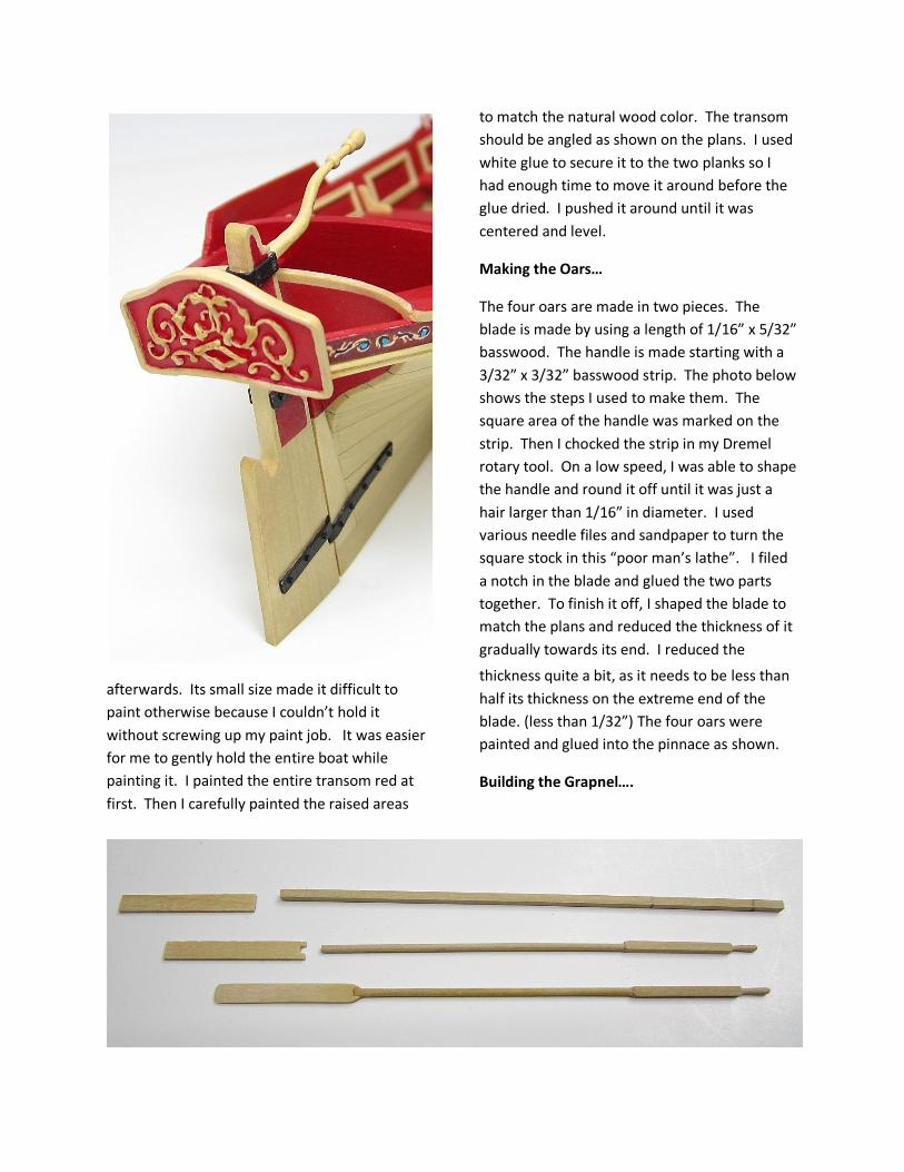
afterwards. Its small size made it difficult to
paint otherwise because I couldn’t hold it
without screwing up my paint job. It was easier
for me to gently hold the entire boat while
painting it. I painted the entire transom red at
first. Then I carefully painted the raised areas
to match the natural wood color. The transom
should be angled as shown on the plans. I used
white glue to secure it to the two planks so I
had enough time to move it around before the
glue dried. I pushed it around until it was
centered and level.
Making the Oars…
The four oars are made in two pieces. The
blade is made by using a length of 1/16” x 5/32”
basswood. The handle is made starting with a
3/32” x 3/32” basswood strip. The photo below
shows the steps I used to make them. The
square area of the handle was marked on the
strip. Then I chocked the strip in my Dremel
rotary tool. On a low speed, I was able to shape
the handle and round it off until it was just a
hair larger than 1/16” in diameter. I used
various needle files and sandpaper to turn the
square stock in this “poor man’s lathe”. I filed
a notch in the blade and glued the two parts
together. To finish it off, I shaped the blade to
match the plans and reduced the thickness of it
gradually towards its end. I reduced the
thickness quite a bit, as it needs to be less than
half its thickness on the extreme end of the
blade. (less than 1/32”) The four oars were
painted and glued into the pinnace as shown.
Building the Grapnel….
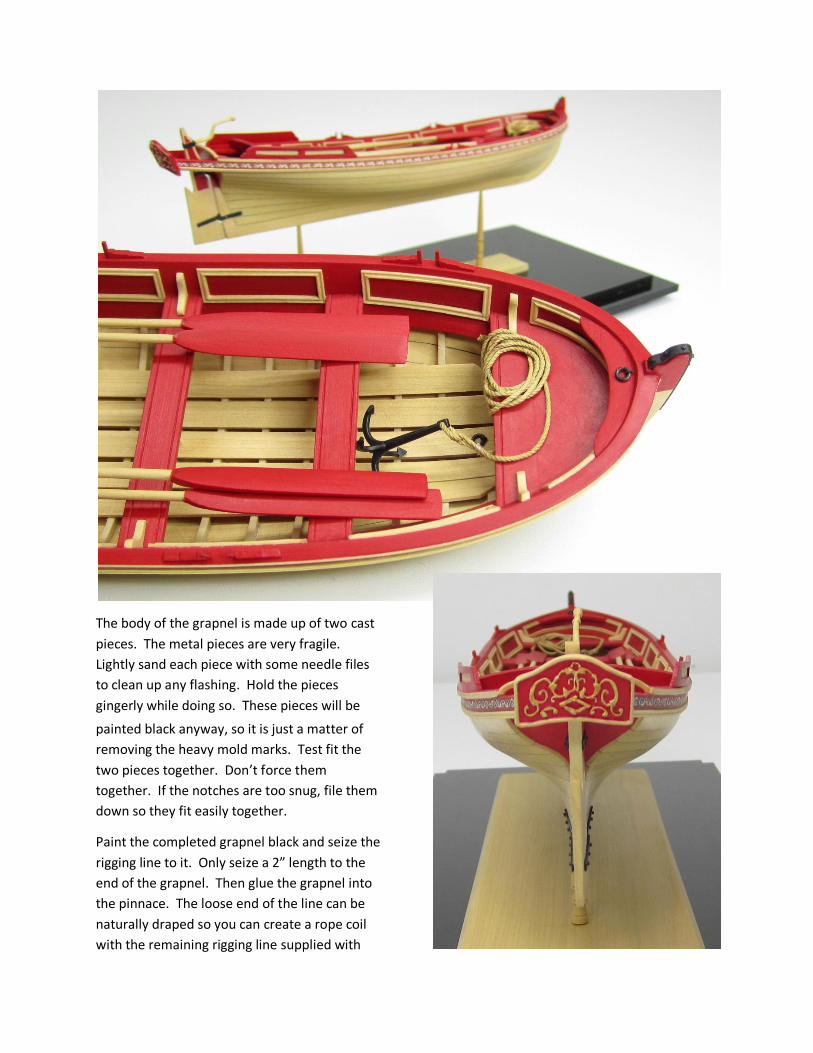
The body of the grapnel is made up of two cast
pieces. The metal pieces are very fragile.
Lightly sand each piece with some needle files
to clean up any flashing. Hold the pieces
gingerly while doing so. These pieces will be
painted black anyway, so it is just a matter of
removing the heavy mold marks. Test fit the
two pieces together. Don’t force them
together. If the notches are too snug, file them
down so they fit easily together.
Paint the completed grapnel black and seize the
rigging line to it. Only seize a 2” length to the
end of the grapnel. Then glue the grapnel into
the pinnace. The loose end of the line can be
naturally draped so you can create a rope coil
with the remaining rigging line supplied with
the kit. Glue the rope coil over the end of the
shorter section so it looks like a naturally
draping and coiled rope.
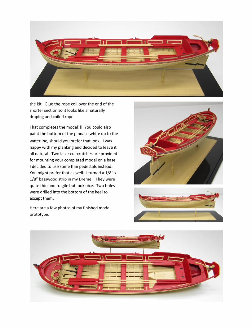
That completes the model!!! You could also
paint the bottom of the pinnace white up to the
waterline, should you prefer that look. I was
happy with my planking and decided to leave it
all natural. Two laser cut crutches are provided
for mounting your completed model on a base.
I decided to use some thin pedestals instead.
You might prefer that as well. I turned a 1/8” x
1/8” basswood strip in my Dremel. They were
quite thin and fragile but look nice. Two holes
were drilled into the bottom of the keel to
except them.
Here are a few photos of my finished model
prototype.