Embed Size (px)
Citation preview
C 25
INSTRUCTION MANUAL
CAP
TURE
AT
SOU
RCE
NR. 148443/012001-10-01
C 25
FILTERMAX
010
1
P
ENGLISH
C 25
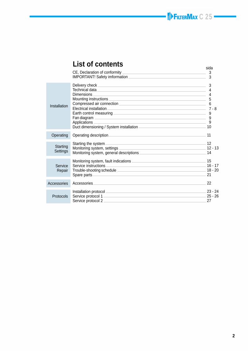
CE, Declaration of conformityIMPORTANT! Safety imformation
Delivery checkTechnical dataDimensionsMounting instructionsCompressed air connectionElectrical installationEarth control measuringFan diagramApplicationsDuct dimensioning / System installation
Operating description
Starting the systemMonitoring system, settingsMonitoring system, general descriptions
Monitoring system, fault indicationsService instructionsTrouble-shooting scheduleSpare parts
Accessories
Installation protocolService protocol 1Service protocol 2
2
sida 3 3
3 4 4 5 6 7 - 8 9 9 9 10
11
12 12 - 13 14
15 16 - 17 18 - 20 21
22
23 - 24 25 - 26 27
List of contents
Starting Settings
ServiceRepair
Accessories
Protocols
Operating
Installation
C 25
3
R
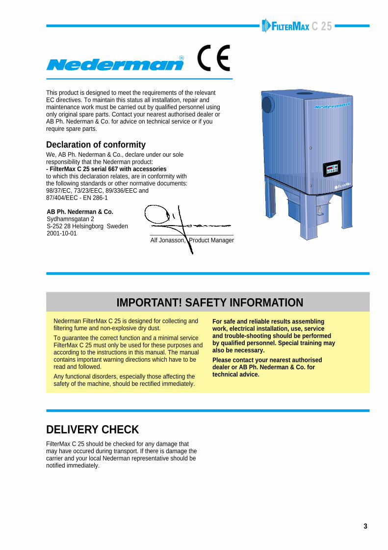
AB Ph. Nederman & Co.Sydhamnsgatan 2S-252 28 Helsingborg Sweden2001-10-01
Alf Jonasson, Product Manager
FILTERMAX
010
1
P
DELIVERY CHECK
This product is designed to meet the requirements of the relevantEC directives. To maintain this status all installation, repair andmaintenance work must be carried out by qualified personnel usingonly original spare parts. Contact your nearest authorised dealer orAB Ph. Nederman & Co. for advice on technical service or if yourequire spare parts.
Declaration of conformityWe, AB Ph. Nederman & Co., declare under our soleresponsibility that the Nederman product:- FilterMax C 25 serial 667 with accessoriesto which this declaration relates, are in conformity withthe following standards or other normative documents:98/37/EC, 73/23/EEC, 89/336/EEC and87/404/EEC - EN 286-1
FilterMax C 25 should be checked for any damage thatmay have occured during transport. If there is damage thecarrier and your local Nederman representative should benotified immediately.
For safe and reliable results assemblingwork, electrical installation, use, serviceand trouble-shooting should be performedby qualified personnel. Special training mayalso be necessary.
Please contact your nearest authoriseddealer or AB Ph. Nederman & Co. fortechnical advice.
IMPORTANT! SAFETY INFORMATIONNederman FilterMax C 25 is designed for collecting andfiltering fume and non-explosive dry dust.
To guarantee the correct function and a minimal serviceFilterMax C 25 must only be used for these purposes andaccording to the instructions in this manual. The manualcontains important warning directions which have to beread and followed.
Any functional disorders, especially those affecting thesafety of the machine, should be rectified immediately.
C 25
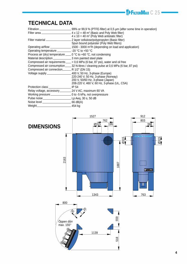
99% or 99,9 % (PTFE-filter) at 0,5 µm (after some time in operation)4 x 12 = 48 m2 (Basic and Poly Web filter)4 x 10 = 40 m2 (Poly Web antistatic filter)2 layer cellulose/polypropylen (Basic filter)Spun bound polyester (Poly Web filters)1500 - 3000 m3/h (depending on load and application)-20 °C to +50 °C0 °C to +60 °C, not condensing3 mm painted steel plate> 0,6 MPa (6 bar, 87 psi), water and oil free32 N-litres / cleaning pulse at 0,6 MPa (6 bar, 87 psi)R 1/2" (DN 15)400 V, 50 Hz, 3-phase (Europe)220-240 V, 50 Hz, 3-phase (Norway)200 V, 50/60 Hz, 3-phase (Japan)208-220 V, 460 V, 60 Hz, 3-phase (UL, CSA)IP 5424 V AC, maximum 60 VA0 to -5 kPa, not overpressureLp Aeq, 30 s, 50 dB66 dB(A)454 kg
FiltrationFilter area
Filter material
Operating airflowOperating temperatureProcess air (dry) temperatureMaterial descriptionCompressed air requirementsCompressed air consumptionCompressed air connectionVoltage supply
Protection classRelay voltage, accessoryWorking pressurePulse noiseNoise levelWeight
4
TECHNICAL DATA
DIMENSIONS
FILTERMAX
762Ø315 195
1527803912
398
1343 763
800
1139
205051
8
2163
1887
Ø31
5
Ø31
5
Öppen dörrmax. 155°
559
C 25
5
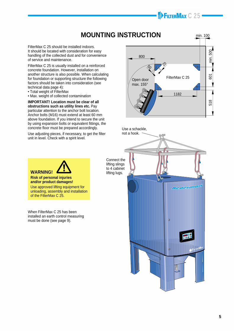
MOUNTING INSTRUCTION
1182
800
50 20
Open doormax. 155°
601
518
min
. 500
min. 100
FilterMax C 25
FilterMax C 25 should be installed indoors.It should be located with consideration for easyhandling of the collected dust and for convenienceof service and maintenance.
FilterMax C 25 is usually installed on a reinforcedconcrete foundation. However, installation onanother structure is also possible. When calculatingfor foundation or supporting structure the followingfactors should be taken into consideration (seetechnical data page 4):• Total weight of FilterMax• Max. weight of collected contamination
IMPORTANT! Location must be clear of allobstructions such as utility lines etc. Payparticular attention to the anchor bolt location.Anchor bolts (M16) must extend at least 60 mmabove foundation. If you intend to secure the unitby using expansion bolts or equivalent fittings, theconcrete floor must be prepared accordingly.
Use adjusting pieces, if necessary, to get the filterunit in level. Check with a spirit level.
WARNING!Risk of personal injuriesand/or product damages!Use approved lifting equipment forunloading, assembly and installationof the FilterMax C 25.
When FilterMax C 25 has beeninstalled an earth control measuringmust be done (see page 9).
FILTERMAX
010
1
P
Use a schackle,not a hook.
Connect thelifting slingsto 4 cabinetlifting lugs.
C 25
6
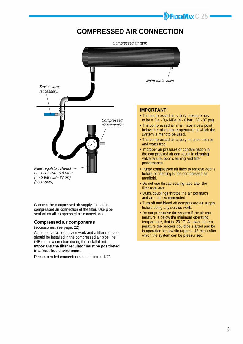
COMPRESSED AIR CONNECTION
Filter regulator, shouldbe set on 0,4 - 0,6 MPa(4 - 6 bar / 58 - 87 psi)(accessory)
IMPORTANT!• The compressed air supply pressure has to be = 0,4 - 0,6 MPa (4 - 6 bar / 58 - 87 psi).• The compressed air shall have a dew point below the minimum temperature at which the system is ment to be used.• The compressed air supply must be both oil and water free.• Improper air pressure or contamination in the compressed air can result in cleaning valve failure, poor cleaning and filter performance.
• Purge compressed air lines to remove debris before connecting to the compressed air manifold.• Do not use thread-sealing tape after the filter regulator.• Quick couplings throttle the air too much and are not recommended.• Turn off and bleed off compressed air supply before doing any service work.• Do not pressurise the system if the air tem- perature is below the minimum operating temperature, that is -20 °C. At lower air tem- perature the process could be started and be in operation for a while (approx. 15 min.) after which the system can be pressurised.
Connect the compressed air supply line to thecompressed air connection of the filter. Use pipesealant on all compressed air connections.
Compressed air components(accessories, see page. 22)A shut off valve for service work and a filter regulatorshould be installed in the compressed air pipe line(NB the flow direction during the installation).Important! the filter regulator must be positionedin a frost free environment.
Recommended connection size: minimum 1/2".
Water drain valve
Compressed air tank
Sevice valve(accessory)
Compressedair connection
C 25
7
010
1
P
P
ACTIVATING THE MENUPush the P-button more than 2 seconds.
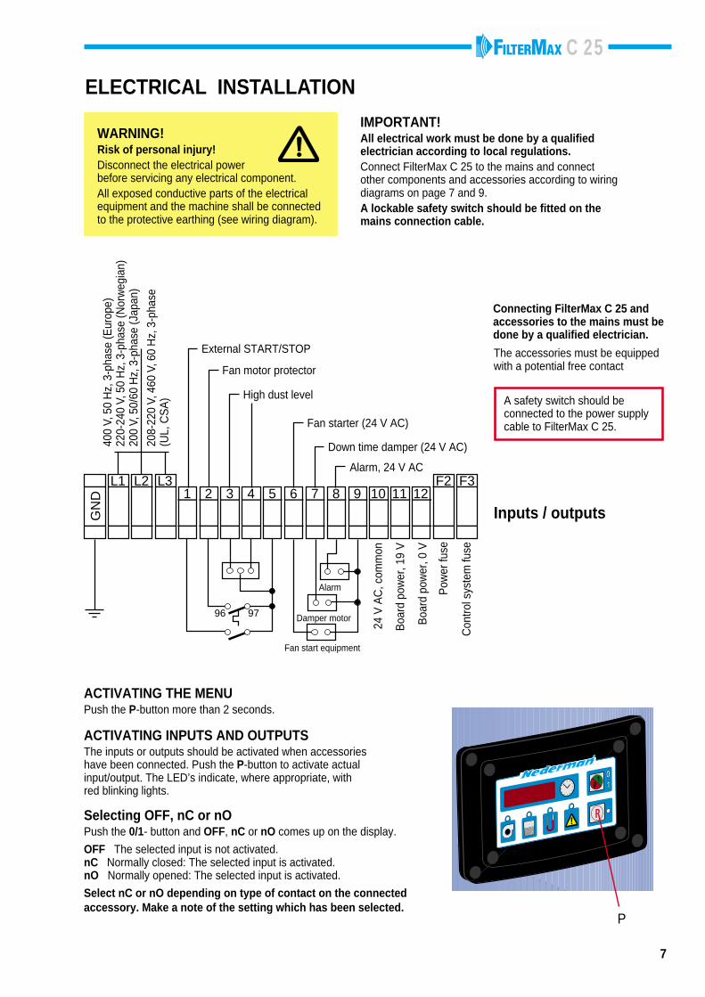
ELECTRICAL INSTALLATION
WARNING!Risk of personal injury!Disconnect the electrical powerbefore servicing any electrical component.All exposed conductive parts of the electricalequipment and the machine shall be connectedto the protective earthing (see wiring diagram).
IMPORTANT!All electrical work must be done by a qualifiedelectrician according to local regulations.Connect FilterMax C 25 to the mains and connectother components and accessories according to wiringdiagrams on page 7 and 9.A lockable safety switch should be fitted on themains connection cable.
1 432 9 12F2 F3L2 L3
GN
D
L111105 876
96 97
400
V, 5
0 H
z, 3
-pha
se (E
urop
e)22
0-24
0 V,
50
Hz,
3-p
hase
(Nor
weg
ian)
200
V, 5
0/60
Hz,
3-p
hase
(Jap
an)
208-
220
V, 4
60 V
, 60
Hz,
3-p
hase
(UL,
CS
A)
External START/STOP
Fan motor protector
High dust level
Alarm, 24 V AC
Down time damper (24 V AC)
Fan starter (24 V AC)
Alarm
Damper motor
Fan start equipment
24 V
AC
, com
mon
Boa
rd p
ower
, 0 V
Pow
er fu
se
Boa
rd p
ower
, 19
V
Con
trol s
yste
m fu
se
Inputs / outputs
A safety switch should beconnected to the power supplycable to FilterMax C 25.
The accessories must be equippedwith a potential free contact
Connecting FilterMax C 25 andaccessories to the mains must bedone by a qualified electrician.
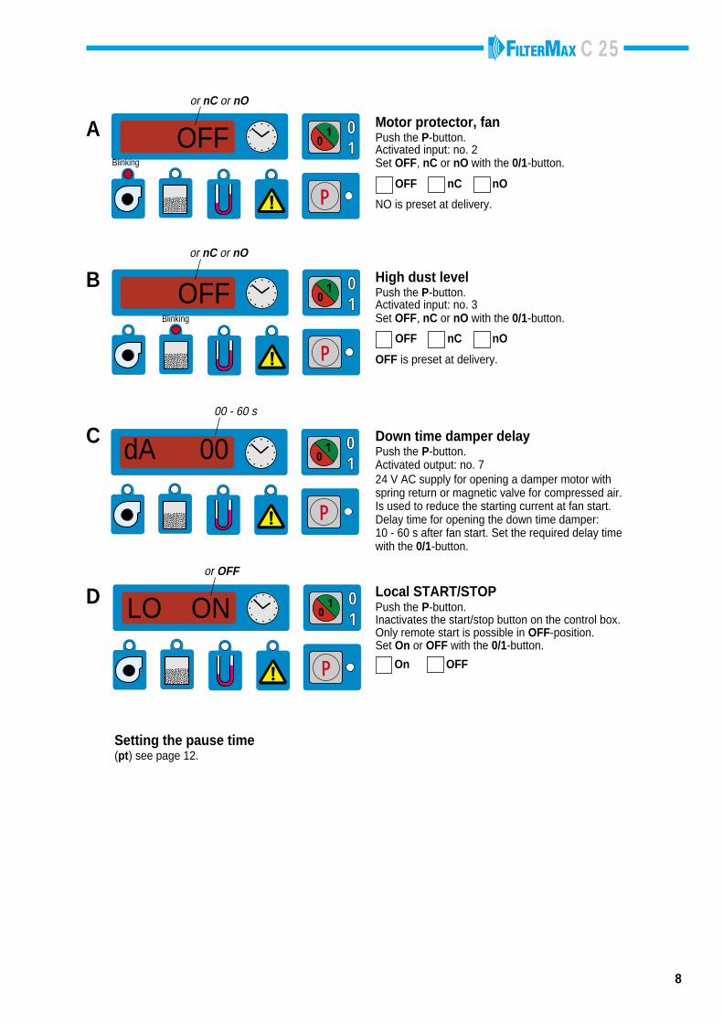
ACTIVATING INPUTS AND OUTPUTSThe inputs or outputs should be activated when accessorieshave been connected. Push the P-button to activate actualinput/output. The LED’s indicate, where appropriate, withred blinking lights.
Selecting OFF, nC or nOPush the 0/1- button and OFF, nC or nO comes up on the display.
OFF The selected input is not activated.nC Normally closed: The selected input is activated.nO Normally opened: The selected input is activated.
Select nC or nO depending on type of contact on the connectedaccessory. Make a note of the setting which has been selected.
C 25
8
010
1
P
Blinking
A OFF
or nC or nO
OFF nC nO
Motor protector, fanPush the P-button.Activated input: no. 2Set OFF, nC or nO with the 0/1-button.
010
1
P
D LO ON
or OFF
Local START/STOPPush the P-button.Inactivates the start/stop button on the control box.Only remote start is possible in OFF-position.Set On or OFF with the 0/1-button.
010
1
P
C dA 00
00 - 60 s
Down time damper delayPush the P-button.Activated output: no. 724 V AC supply for opening a damper motor withspring return or magnetic valve for compressed air.Is used to reduce the starting current at fan start.Delay time for opening the down time damper:10 - 60 s after fan start. Set the required delay timewith the 0/1-button.
010
1
P
B OFF
or nC or nO
Blinking
High dust levelPush the P-button.Activated input: no. 3Set OFF, nC or nO with the 0/1-button.
OFF nC nO
NO is preset at delivery.
OFF is preset at delivery.
On OFF
Setting the pause time(pt) see page 12.
C 25
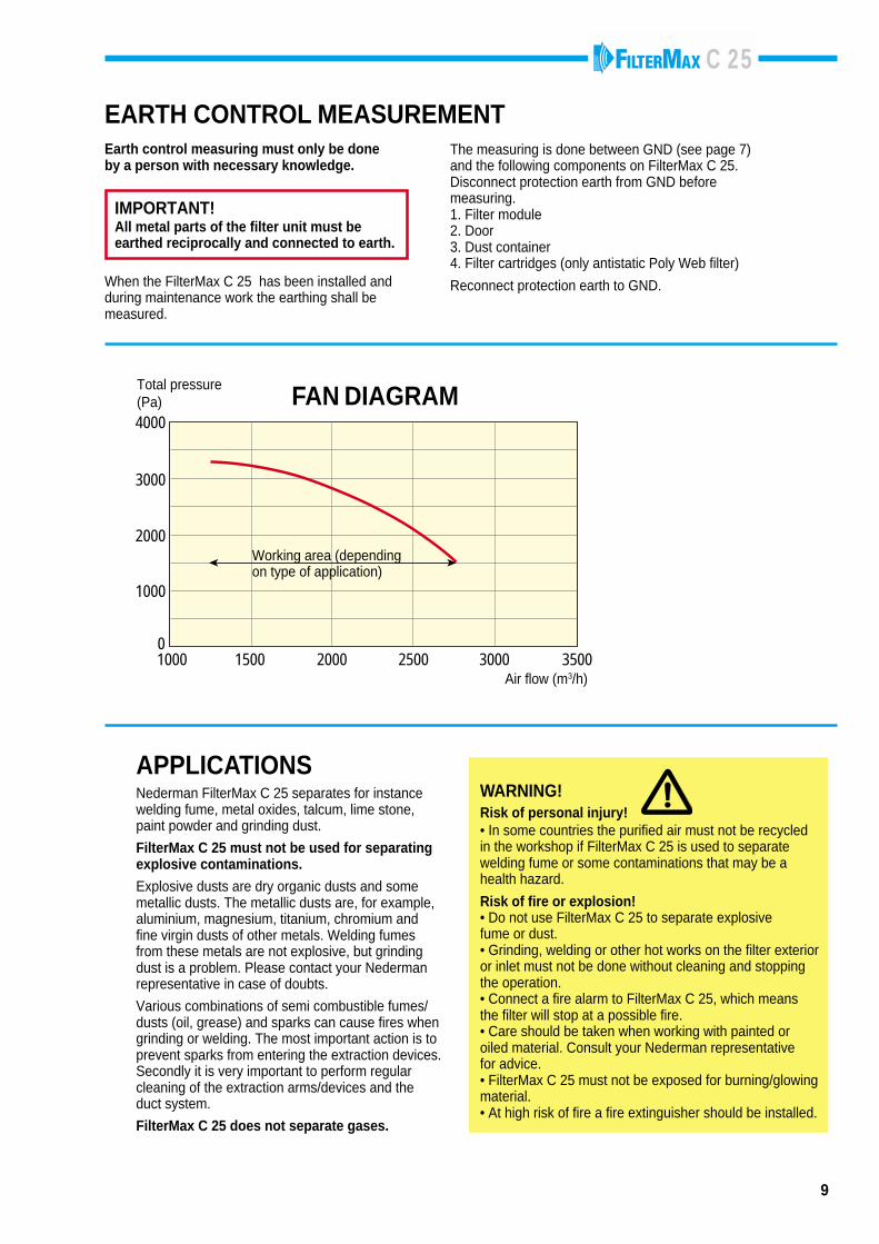
When the FilterMax C 25 has been installed andduring maintenance work the earthing shall bemeasured.
9
EARTH CONTROL MEASUREMENTEarth control measuring must only be doneby a person with necessary knowledge.
IMPORTANT!All metal parts of the filter unit must beearthed reciprocally and connected to earth.
The measuring is done between GND (see page 7)and the following components on FilterMax C 25.Disconnect protection earth from GND beforemeasuring.1. Filter module2. Door3. Dust container4. Filter cartridges (only antistatic Poly Web filter)
Reconnect protection earth to GND.
1000
4000
1000
0
2000
3000
35003000250020001500
Total pressure(Pa)
Air flow (m3/h)
FAN DIAGRAM
Nederman FilterMax C 25 separates for instancewelding fume, metal oxides, talcum, lime stone,paint powder and grinding dust.
FilterMax C 25 must not be used for separatingexplosive contaminations.
Explosive dusts are dry organic dusts and somemetallic dusts. The metallic dusts are, for example,aluminium, magnesium, titanium, chromium andfine virgin dusts of other metals. Welding fumesfrom these metals are not explosive, but grindingdust is a problem. Please contact your Nedermanrepresentative in case of doubts.
Various combinations of semi combustible fumes/dusts (oil, grease) and sparks can cause fires whengrinding or welding. The most important action is toprevent sparks from entering the extraction devices.Secondly it is very important to perform regularcleaning of the extraction arms/devices and theduct system.
FilterMax C 25 does not separate gases.
WARNING!Risk of personal injury!• In some countries the purified air must not be recycledin the workshop if FilterMax C 25 is used to separatewelding fume or some contaminations that may be ahealth hazard.
Risk of fire or explosion!• Do not use FilterMax C 25 to separate explosivefume or dust.• Grinding, welding or other hot works on the filter exterioror inlet must not be done without cleaning and stoppingthe operation.• Connect a fire alarm to FilterMax C 25, which meansthe filter will stop at a possible fire.• Care should be taken when working with painted oroiled material. Consult your Nederman representativefor advice.• FilterMax C 25 must not be exposed for burning/glowingmaterial.• At high risk of fire a fire extinguisher should be installed.
APPLICATIONS
Working area (dependingon type of application)
C 25
10
FILTERMAX
010
1
P
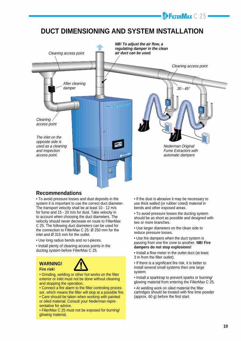
30 - 45°
DUCT DIMENSIONING AND SYSTEM INSTALLATION
Cleaning access point
Cleaning access point
NB! To adjust the air flow, aregulating damper in the cleanair duct can be used.
Nederman OriginalFume Extractors withautomatic dampers
After cleaningdamper
The inlet on theopposite side isused as a cleaningand inspectionaccess point.
Recommendations• To avoid pressure losses and dust deposits in thesystem it is important to use the correct duct diameter.The transport velocity shall be at least 10 - 12 m/sfor fume and 15 - 20 m/s for dust. Take velocity into account when choosing the duct diameters. Thevelocity should never decrease en route to FilterMaxC 25. The following duct diameters can be used forthe connection to FilterMax C 25: Ø 250 mm for theinlet and Ø 315 mm for the outlet.• Use long radius bends and no t-pieces.• Install plenty of cleaning access points in theducting system before FilterMax C 25.
• If the dust is abrasive it may be necessary touse thick walled (or rubber coted) material inbends and other exposed areas.• To avoid pressure losses the ducting systemshould be as short as possible and designed withtwo or more branches.• Use larger diameters on the clean side toreduce pressure losses.• Use fire dampers when the duct system ispassing from one fire zone to another. NB! Firedampers do not stop explosions!• Install a flow meter in the outlet duct (at least3 m from the filter outlet).• If there is a significant fire risk, it is better toinstall several small systems then one largesystem.• Install a sparktrap to prevent sparks or burning/glowing material from entering the FilterMax C 25.
• At welding work on oiled material the filtercartridges should be treated with fine lime powder(approx. 60 g) before the first start.
Cleaningaccess point
WARNING!Fire risk!• Grinding, welding or other hot works on the filterexterior or inlet must not be done without cleaningand stopping the operation.• Connect a fire alarm to the filter controling proces-sor, which means the filter will stop at a possible fire.• Care should be taken when working with paintedor oiled material. Consult your Nederman repre-sentative for advice.• FilterMax C 25 must not be exposed for burning/glowing material.
C 25
11
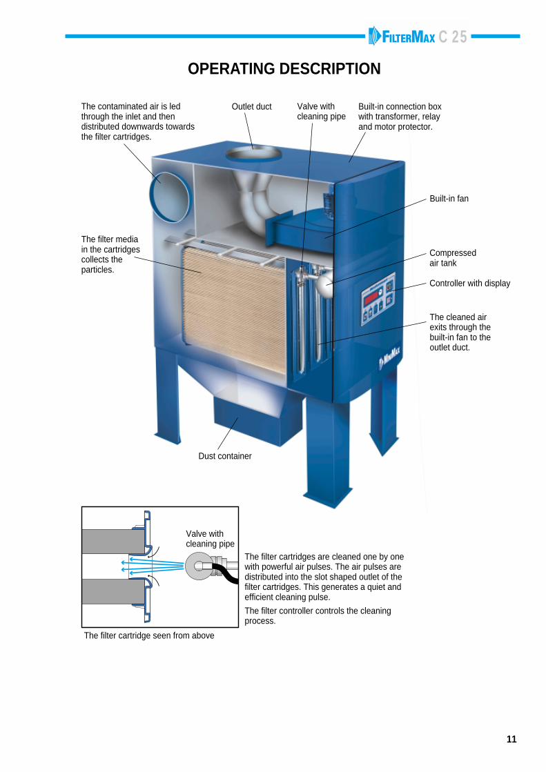
OPERATING DESCRIPTION
The filter mediain the cartridgescollects theparticles.
The contaminated air is ledthrough the inlet and thendistributed downwards towardsthe filter cartridges.
Outlet duct Valve withcleaning pipe
Built-in connection boxwith transformer, relayand motor protector.
The cleaned airexits through thebuilt-in fan to theoutlet duct.
Dust container
Built-in fan
Compressedair tank
Controller with display
Valve withcleaning pipe
The filter cartridge seen from above
The filter cartridges are cleaned one by onewith powerful air pulses. The air pulses aredistributed into the slot shaped outlet of thefilter cartridges. This generates a quiet andefficient cleaning pulse.
The filter controller controls the cleaningprocess.
C 25
12
F TERMAX
010
1
P
Regulatingdamper
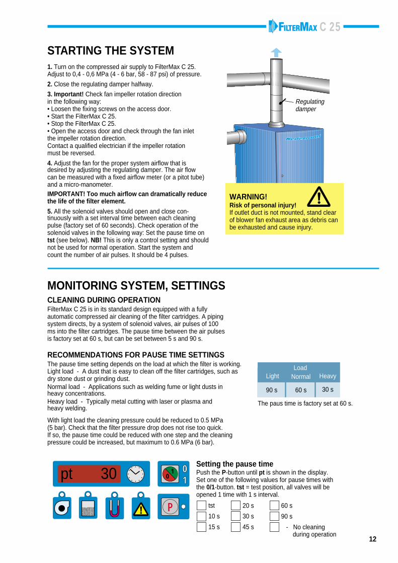
STARTING THE SYSTEM1. Turn on the compressed air supply to FilterMax C 25.Adjust to 0,4 - 0,6 MPa (4 - 6 bar, 58 - 87 psi) of pressure.
2. Close the regulating damper halfway.
3. Important! Check fan impeller rotation directionin the following way:• Loosen the fixing screws on the access door.• Start the FilterMax C 25.• Stop the FilterMax C 25.• Open the access door and check through the fan inletthe impeller rotation direction.Contact a qualified electrician if the impeller rotationmust be reversed.
4. Adjust the fan for the proper system airflow that isdesired by adjusting the regulating damper. The air flowcan be measured with a fixed airflow meter (or a pitot tube)and a micro-manometer.IMPORTANT! Too much airflow can dramatically reducethe life of the filter element.
5. All the solenoid valves should open and close con-tinuously with a set interval time between each cleaningpulse (factory set of 60 seconds). Check operation of thesolenoid valves in the following way: Set the pause time ontst (see below). NB! This is only a control setting and shouldnot be used for normal operation. Start the system andcount the number of air pulses. It should be 4 pulses.
WARNING!Risk of personal injury!If outlet duct is not mounted, stand clearof blower fan exhaust area as debris canbe exhausted and cause injury.
010
1
P
Setting the pause timePush the P-button until pt is shown in the display.Set one of the following values for pause times withthe 0/1-button. tst = test position, all valves will beopened 1 time with 1 s interval.
pt 30
MONITORING SYSTEM, SETTINGSCLEANING DURING OPERATIONFilterMax C 25 is in its standard design equipped with a fullyautomatic compressed air cleaning of the filter cartridges. A pipingsystem directs, by a system of solenoid valves, air pulses of 100ms into the filter cartridges. The pause time between the air pulsesis factory set at 60 s, but can be set between 5 s and 90 s.
RECOMMENDATIONS FOR PAUSE TIME SETTINGSThe pause time setting depends on the load at which the filter is working.Light load - A dust that is easy to clean off the filter cartridges, such asdry stone dust or grinding dust.Normal load - Applications such as welding fume or light dusts inheavy concentrations.Heavy load - Typically metal cutting with laser or plasma andheavy welding.
With light load the cleaning pressure could be reduced to 0.5 MPa(5 bar). Check that the filter pressure drop does not rise too quick.If so, the pause time could be reduced with one step and the cleaningpressure could be increased, but maximum to 0.6 MPa (6 bar).
Heavy
30 s
Normal
60 s
Light
90 s
Load
The paus time is factory set at 60 s.
tst
10 s
15 s
20 s
30 s
45 s
60 s
90 s
- No cleaning during operation
C 25
13
010
1
P
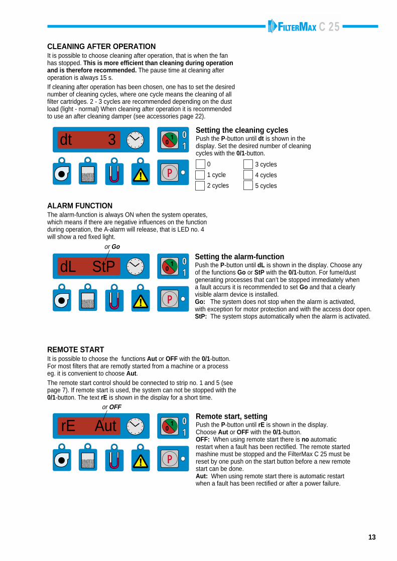
Setting the cleaning cyclesPush the P-button until dt is shown in thedisplay. Set the desired number of cleaningcycles with the 0/1-button.
0
1 cycle
2 cycles
3 cycles
4 cycles
5 cycles
010
1
P
CLEANING AFTER OPERATIONIt is possible to choose cleaning after operation, that is when the fanhas stopped. This is more efficient than cleaning during operationand is therefore recommended. The pause time at cleaning afteroperation is always 15 s.If cleaning after operation has been chosen, one has to set the desirednumber of cleaning cycles, where one cycle means the cleaning of allfilter cartridges. 2 - 3 cycles are recommended depending on the dustload (light - normal) When cleaning after operation it is recommendedto use an after cleaning damper (see accessories page 22).
ALARM FUNCTIONThe alarm-function is always ON when the system operates,which means if there are negative influences on the functionduring operation, the A-alarm will release, that is LED no. 4will show a red fixed light.
Setting the alarm-functionPush the P-button until dL is shown in the display. Choose anyof the functions Go or StP with the 0/1-button. For fume/dustgenerating processes that can’t be stopped immediately whena fault accurs it is recommended to set Go and that a clearlyvisible alarm device is installed.Go: The system does not stop when the alarm is activated,with exception for motor protection and with the access door open.StP: The system stops automatically when the alarm is activated.
REMOTE STARTIt is possible to choose the functions Aut or OFF with the 0/1-button.For most filters that are remotly started from a machine or a processeg. it is convenient to choose Aut.The remote start control should be connected to strip no. 1 and 5 (seepage 7). If remote start is used, the system can not be stopped with the0/1-button. The text rE is shown in the display for a short time.
dt 3
dL StPor Go
010
1
P
rE AutRemote start, settingPush the P-button until rE is shown in the display.Choose Aut or OFF with the 0/1-button.OFF: When using remote start there is no automaticrestart when a fault has been rectified. The remote startedmashine must be stopped and the FilterMax C 25 must bereset by one push on the start button before a new remotestart can be done.Aut: When using remote start there is automatic restartwhen a fault has been rectified or after a power failure.
or OFF
C 25
010
1
P
010
1
P
010
1
P
010
1
P
010
1
P
1 2 4
r E
14
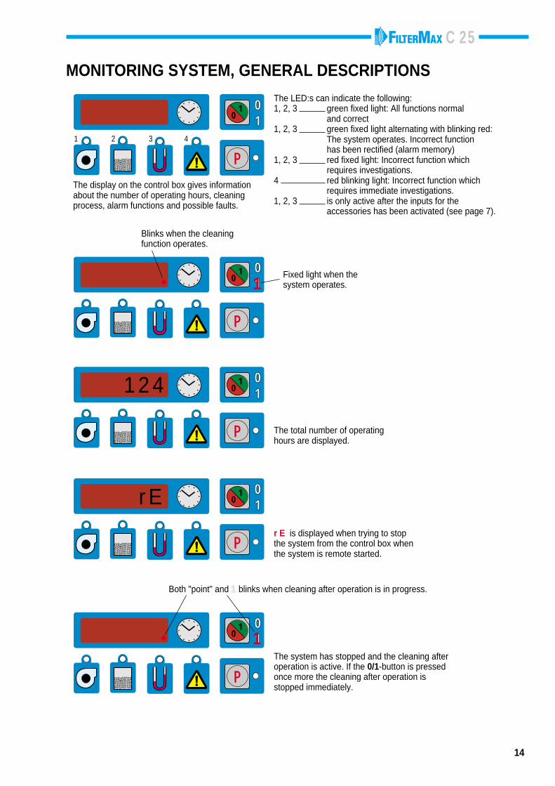
1 2 3 4
MONITORING SYSTEM, GENERAL DESCRIPTIONS
The LED:s can indicate the following:1, 2, 3 green fixed light: All functions normal
and correct1, 2, 3 green fixed light alternating with blinking red:
The system operates. Incorrect functionhas been rectified (alarm memory)
1, 2, 3 red fixed light: Incorrect function whichrequires investigations.
4 red blinking light: Incorrect function whichrequires immediate investigations.
1, 2, 3 is only active after the inputs for theaccessories has been activated (see page 7).
Blinks when the cleaningfunction operates.
Fixed light when thesystem operates.1
The display on the control box gives informationabout the number of operating hours, cleaningprocess, alarm functions and possible faults.
The total number of operatinghours are displayed.
r E is displayed when trying to stopthe system from the control box whenthe system is remote started.
Both "point" and 1 blinks when cleaning after operation is in progress.
1The system has stopped and the cleaning afteroperation is active. If the 0/1-button is pressedonce more the cleaning after operation isstopped immediately.
C 25
15
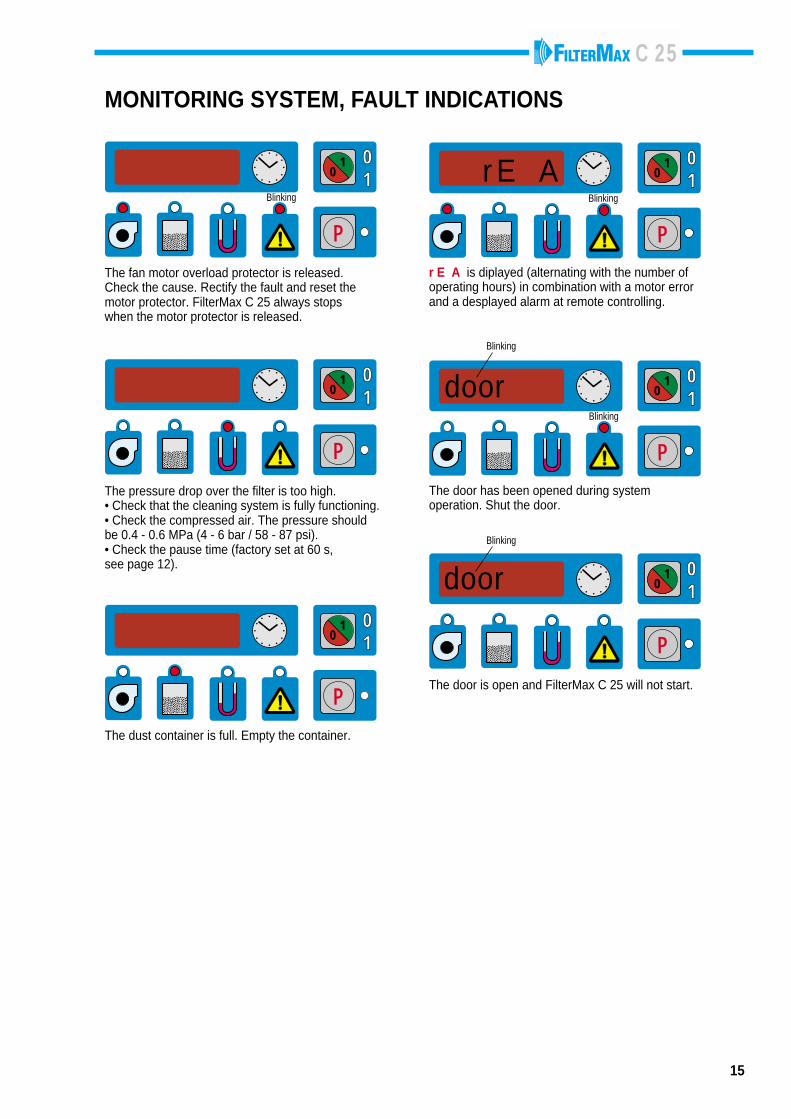
MONITORING SYSTEM, FAULT INDICATIONS
010
1
P
010
1
P
r E ABlinking
The fan motor overload protector is released.Check the cause. Rectify the fault and reset themotor protector. FilterMax C 25 always stopswhen the motor protector is released.
Blinking
r E A is diplayed (alternating with the number ofoperating hours) in combination with a motor errorand a desplayed alarm at remote controlling.
010
1
P
The pressure drop over the filter is too high.• Check that the cleaning system is fully functioning.• Check the compressed air. The pressure shouldbe 0.4 - 0.6 MPa (4 - 6 bar / 58 - 87 psi).• Check the pause time (factory set at 60 s,see page 12).
010
1
P
doorBlinking
The door has been opened during systemoperation. Shut the door.
Blinking
010
1
P
The dust container is full. Empty the container.
010
1
P
door
The door is open and FilterMax C 25 will not start.
Blinking
C 25
16
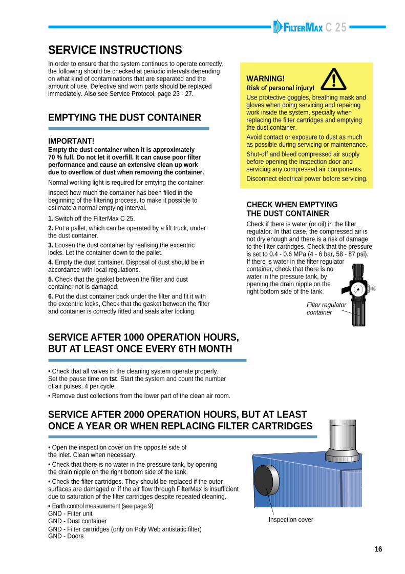
SERVICE INSTRUCTIONSIn order to ensure that the system continues to operate correctly,the following should be checked at periodic intervals dependingon what kind of contaminations that are separated and theamount of use. Defective and worn parts should be replacedimmediately. Also see Service Protocol, page 23 - 27.
IMPORTANT!Empty the dust container when it is approximately70 % full. Do not let it overfill. It can cause poor filterperformance and cause an extensive clean up workdue to overflow of dust when removing the container.
Normal working light is required for emtying the container.
Inspect how much the container has been filled in thebeginning of the filtering process, to make it possible toestimate a normal emptying interval.
1. Switch off the FilterMax C 25.2. Put a pallet, which can be operated by a lift truck, underthe dust container.3. Loosen the dust container by realising the excentriclocks. Let the container down to the pallet.4. Empty the dust container. Disposal of dust should be inaccordance with local regulations.5. Check that the gasket between the filter and dustcontainer not is damaged.6. Put the dust container back under the filter and fit it withthe excentric locks, Check that the gasket between the filterand container is correctly fitted and seals after locking.
EMPTYING THE DUST CONTAINER
SERVICE AFTER 1000 OPERATION HOURS,BUT AT LEAST ONCE EVERY 6TH MONTH
SERVICE AFTER 2000 OPERATION HOURS, BUT AT LEASTONCE A YEAR OR WHEN REPLACING FILTER CARTRIDGES
• Open the inspection cover on the opposite side ofthe inlet. Clean when necessary.• Check that there is no water in the pressure tank, by openingthe drain nipple on the right bottom side of the tank.• Check the filter cartridges. They should be replaced if the outersurfaces are damaged or if the air flow through FilterMax is insufficientdue to saturation of the filter cartridges despite repeated cleaning.• Earth control measurement (see page 9)GND - Filter unitGND - Dust containerGND - Filter cartridges (only on Poly Web antistatic filter)GND - Doors
• Check that all valves in the cleaning system operate properly.Set the pause time on tst. Start the system and count the numberof air pulses, 4 per cycle.• Remove dust collections from the lower part of the clean air room.
WARNING!Risk of personal injury!Use protective goggles, breathing mask andgloves when doing servicing and repairingwork inside the system, specially whenreplacing the filter cartridges and emptyingthe dust container.Avoid contact or exposure to dust as muchas possible during servicing or maintenance.Shut-off and bleed compressed air supplybefore opening the inspection door andservicing any compressed air components.Disconnect electrical power before servicing.
CHECK WHEN EMPTYINGTHE DUST CONTAINER
010
1
P
Inspection cover
Filter regulatorcontainer
Check if there is water (or oil) in the filterregulator. In that case, the compressed air isnot dry enough and there is a risk of damageto the filter cartridges. Check that the pressureis set to 0.4 - 0.6 MPa (4 - 6 bar, 58 - 87 psi).If there is water in the filter regulatorcontainer, check that there is nowater in the pressure tank, byopening the drain nipple on theright bottom side of the tank.
C 25
17
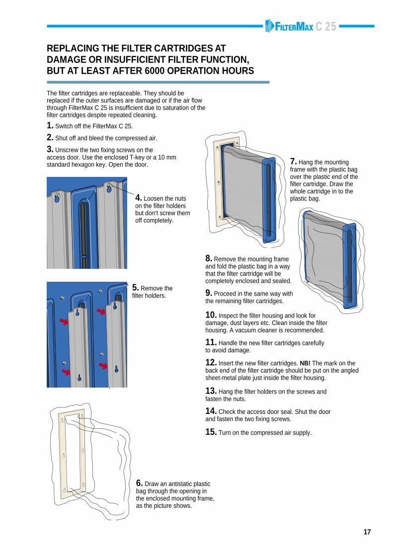
REPLACING THE FILTER CARTRIDGES ATDAMAGE OR INSUFFICIENT FILTER FUNCTION,BUT AT LEAST AFTER 6000 OPERATION HOURS
The filter cartridges are replaceable. They should bereplaced if the outer surfaces are damaged or if the air flowthrough FilterMax C 25 is insufficient due to saturation of thefilter cartridges despite repeated cleaning.
1. Switch off the FilterMax C 25.
2. Shut off and bleed the compressed air.
3. Unscrew the two fixing screws on theaccess door. Use the enclosed T-key or a 10 mmstandard hexagon key. Open the door.
4. Loosen the nutson the filter holdersbut don’t screw themoff completely.
5. Remove thefilter holders.
6. Draw an antistatic plasticbag through the opening inthe enclosed mounting frame,as the picture shows.
7. Hang the mountingframe with the plastic bagover the plastic end of thefilter cartridge. Draw thewhole cartridge in to theplastic bag.
8. Remove the mounting frameand fold the plastic bag in a waythat the filter cartridge will becompletely enclosed and sealed.
9. Proceed in the same way withthe remaining filter cartridges.
10. Inspect the filter housing and look fordamage, dust layers etc. Clean inside the filterhousing. A vacuum cleaner is recommended.
11. Handle the new filter cartridges carefullyto avoid damage.
12. Insert the new filter cartridges. NB! The mark on theback end of the filter cartridge should be put on the angledsheet-metal plate just inside the filter housing.
13. Hang the filter holders on the screws andfasten the nuts.
14. Check the access door seal. Shut the doorand fasten the two fixing screws.
15. Turn on the compressed air supply.
C 25
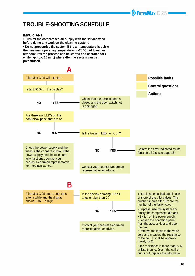
FilterMax C 25 will not start.
A
NO YES
Is text dOOr on the display?
18
TROUBLE-SHOOTING SCHEDULE
IMPORTANT!• Turn off the compressed air supply with the service valvebefore doing any work on the cleaning system.• Do not pressurise the system if the air temperature is belowthe minimum operating temperature (= -20 °C). At lower airtemperatures the process can be started and operated for awhile (approx. 15 min.) whereafter the system can bepressurised.
Check the power supply and thefuses in the connection box. If thepower supply and the fuses arefully functional, contact yournearest Nederman representativefor more assistence.
YESNO
Are there any LED’s on thecontrolbox panel that are on.
Correct the error indicated by thefunction LED’s, see page 15.
YESNO
Is the A-alarm LED no. 7, on?
Contact your nearest Nedermanrepresentative for advice.
Possible faults
Control questions
Actions
NO
Is the display showing ERR +another digit than 0 ?
YES
Contact your nearest Nedermanrepresentative for advice.
There is an electrical fault in oneor more of the pilot valves. Thenumber shown after Err are thenumber of the faulty valve.• Depressurise the system andempty the compressed air tank.• Switch off the power supply.• Loosen the operation panelfrom the access door and openthe box.• Remove the leads to the valvecoils and measure the resistanceof the coil. It shall be approxi-mately xx Ω.If the resistance is more than xx Ωor less than xx Ω or if the coil cir-cuit is cut, replace the pilot valve.
FilterMax C 25 starts, but stopsafter a while and the displayshows ERR + a digit.
B
Check that the access door isclosed and the door switch notis damaged.
C 25
19
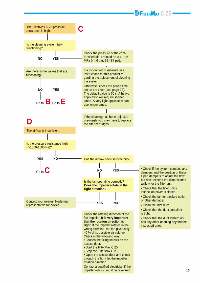
NO YES • Check if the system contains anydampers and the position of these.Open dampers to adjust the flow,but don’t exceed the dimensionedairflow for the filter unit.• Check that the filter unit’sinspection cover is closed.• Check the fan for blocked outletor other damage.• Clean the inlet duct.• Check that the dust containeris tight.• Check that the duct system nothas any other opening beyond theinspected ones.
NOYES
Is the fan operating correctly?Does the impeller rotate in theright direction?
Contact your nearest Nedermanrepresentative for advice.
Has the airflow been satisfactory?NO
The airflow is insufficient.
Go to C
YES
Is the pressure resistance high( >1000-1500 Pa)?
Check the rotating direction of thefan impeller. It is very importantthat the rotation direction isright. If the impeller rotates in thewrong direction, the fan gives only40 % of its possible air volume.Check in the following way:• Loosen the fixing screws on theaccess door.• Start the FilterMax C 25.• Stop the FilterMax C 25.• Open the access door and checkthrough the fan inlet the impellerrotation direction.Contact a qualified electrician if theimpeller rotation must be reversed.
D
YESNO
The FilterMax C 25 pressureresistance is high. C
Are there some valves that arefunctioning?
Go to EGo to B
NO YES
Is the cleaning system fullyfunctioning?
If a dP-control is installed, seeinstructions for this product re-garding the adjustment of cleaningthe system.Otherwise, check the pause timeset on the timer (see page 12).The default value is 60 s. A heavyapplication will require shortertimes. A very light application canuse longer times.
Check the pressure of the com-pressed air. It should be 0.4 - 0.6MPa (4 - 6 bar, 58 - 87 psi).
If the cleaning has been adjustedpreviously you may have to replacethe filter cartridges.
C 25
NOYES
NOYES
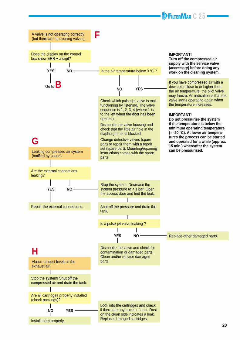
Are the external connectionsleaking?
Stop the system. Decrease thesystem pressure to < 1 bar. Openthe access door and find the leak.
Shut off the pressure and drain thetank.
Is a pulse-jet valve leaking ?
Dismantle the valve and check forcontamination or damaged parts.Clean and/or replace damagedparts.
Replace other damaged parts.
Repair the external connections.
GLeaking compressed air system(notified by sound)
A valve is not operating correctly(but there are functioning valves). F
NOYES
Go to BNO YES
Is the air temperature below 0 °C ?
If you have compressed air with adew point close to or higher thenthe air temperature, the pilot valvemay freeze. An indication is that thevalve starts operating again whenthe temperature increases.
IMPORTANT!Do not pressurise the systemif the temperature is below theminimum operating temperature(= -20 °C). At lower air tempera-tures the process can be startedand operated for a while (approx.15 min.) whereafter the systemcan be pressurised.
Check which pulse-jet valve is mal-functioning by listening. The valvesequence is 1, 2, 3, 4 (where 1 isto the left when the door has beenopened).
Dismantle the valve housing andcheck that the little air hole in thediaphragm not is blocked.
Change defective valves (sparepart) or repair them with a repairset (spare part). Mounting/repairinginstructions comes with the spareparts.
Does the display on the controlbox show ERR + a digit?
IMPORTANT!Turn off the compressed airsupply with the service valve(accessory) before doing anywork on the cleaning system.
20
YESNO
Install them properly.
Look into the cartridges and checkif there are any traces of dust. Duston the clean side indicates a leak.Replace damaged cartridges.
Abnormal dust levels in theexhaust air.
H
Stop the system! Shut off thecompressed air and drain the tank.
Are all cartridges properly installed(check packings)?
C 25
21
4
1
13
01
01
5
1416
3 89
7
15
01
01
6
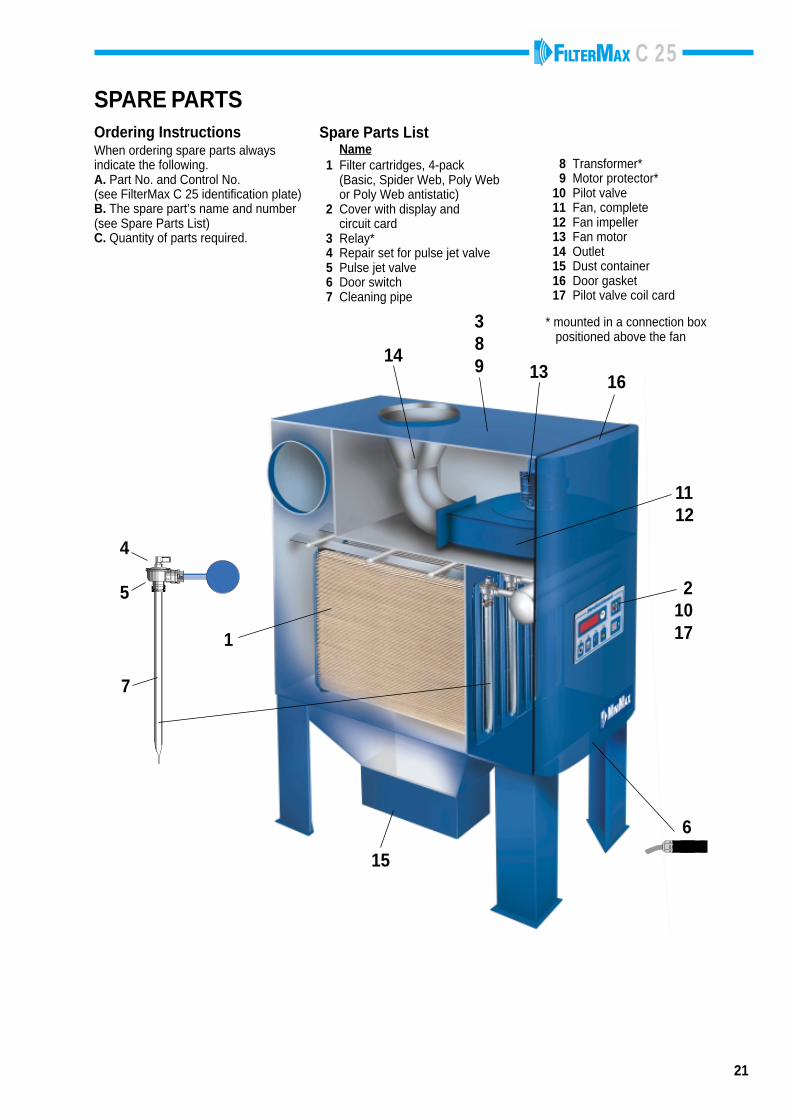
SPARE PARTSSpare Parts List Name 1 Filter cartridges, 4-pack (Basic, Spider Web, Poly Web or Poly Web antistatic) 2 Cover with display and circuit card 3 Relay* 4 Repair set for pulse jet valve 5 Pulse jet valve 6 Door switch 7 Cleaning pipe
8 Transformer* 9 Motor protector*10 Pilot valve11 Fan, complete12 Fan impeller13 Fan motor14 Outlet15 Dust container16 Door gasket17 Pilot valve coil card
Ordering InstructionsWhen ordering spare parts alwaysindicate the following.A. Part No. and Control No.(see FilterMax C 25 identification plate)B. The spare part’s name and number(see Spare Parts List)C. Quantity of parts required.
* mounted in a connection box positioned above the fan
21017
1112
C 25
22
ACCESSORIES
AFTER CLEANING DAMPER(Not a Nederman product) The damper closesthe duct when FilterMax C 25 is shut off, which willprevent dust from being transported back into theworkshop by the air pulses from the down timecleaning. The damper should be mounted closeto the FilterMax C 25 inlet (see page 7 and 10).
FILTER CARTRIDGESBasicDual layer cellulose/polypropylen.Suitable for fumes and fine particles.Efficiency: 99 % at 0,5 µm (after some time in operation)Filter area: 12 m2
BIA class CPart no. 12373300
Poly WebSpun bound polyester.Suitable for medium to coarse particles.Efficiency: 99 % at 0,5 µm (after some time in operation)Filter area: 12 m2
WashableBIA class CPart no. 12373323
Poly Web PTFEPTFE membrane, laminated to spun bound polyester.Suitable for fine to medium particles.Efficiency: 99,9 % at 0,5 µm (after some time in operation)Filter area: 12 m2
WashableBIA class CPart no. 12373325
Poly Web antistatic and Poly Web antistatic PTFEAluminium coated spun bound polyester.Suitable for ignition sencitive, medium to coarse particles.Efficiency: 99 % at 0,5 µm / 99,9 % at 0,5 µm (PTFE)Filter area: 10 m2
WashableBIA class CPart no. 12373303Part no. 12373335 (PTFE)
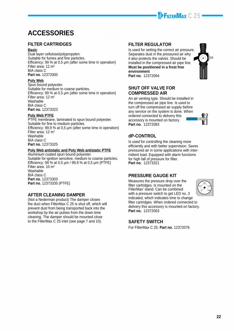
FILTER REGULATORIs used for setting the correct air pressure.Separates dust in the pressured air whyit also protects the valves. Should beinstalled in the compressed air pipe line.Must be positioned in a frost freeenvironmentPart no. 12372064
SHUT OFF VALVE FORCOMPRESSED AIRAn air venting type. Should be installed inthe compressed air pipe line. Is used toturn off the compressed air supply beforeany service on the system is done. Whenordered connected to delivery thisaccessory is mounted on factory.Part no. 12372083
dP-CONTROLIs used for controlling the cleaning moreefficiently and with better supervision. Savespressured air in some applications with inter-mittent load. Equipped with alarm functionsfor high fall of pressure for filter.Part no. 12373321
PRESSURE GAUGE KITMeasures the pressure drop over thefilter cartridges. Is mounted on theFilterMax’ stand. Can be combinedwith a pressure switch to get LED no. 3indicated, which indicates time to changefilter cartridges. When ordered connected todelivery this accessory is mounted on factory.Part no. 12372063
0
500 1500
2000
1500
SAFETY SWITCHFor FilterMax C 25. Part no. 12372076
C 25
FilterMax C 25 No.
23
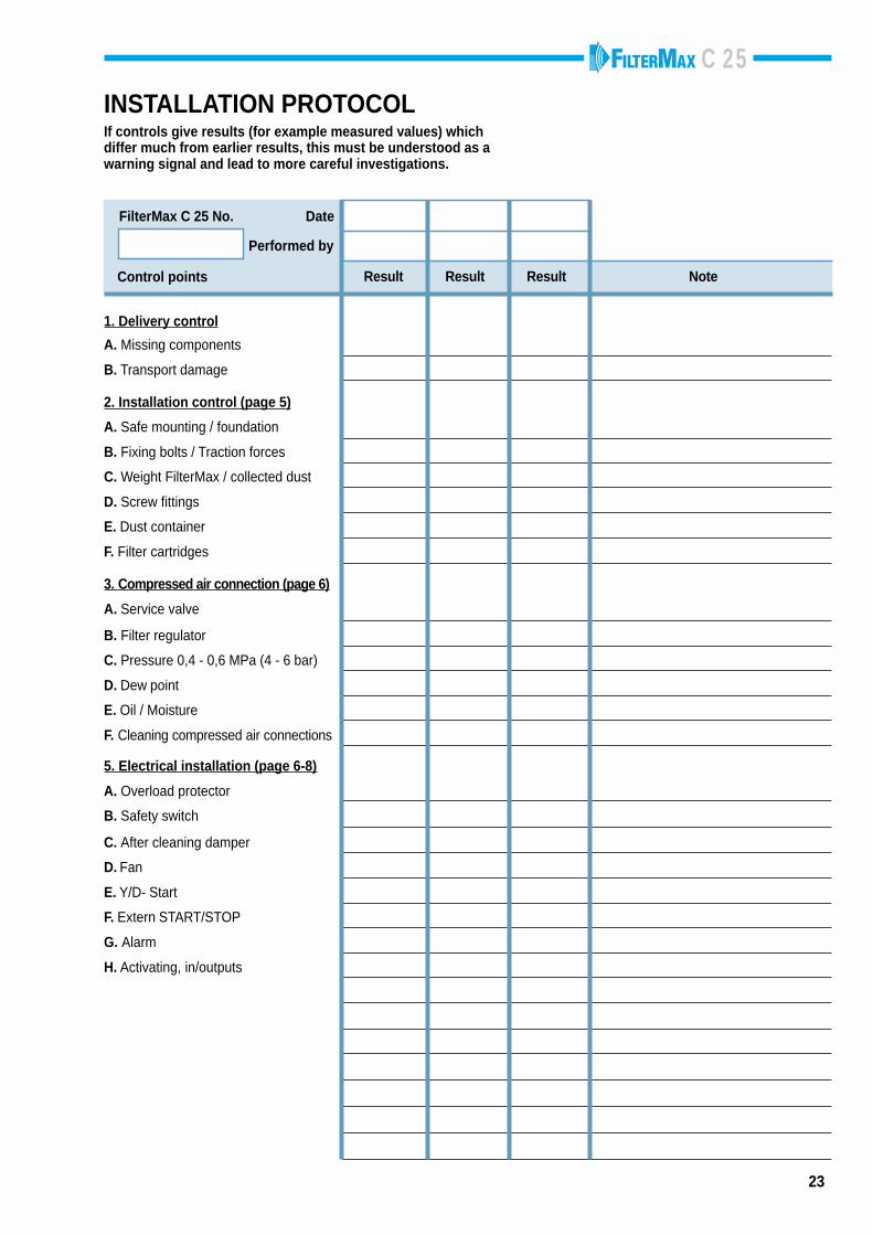
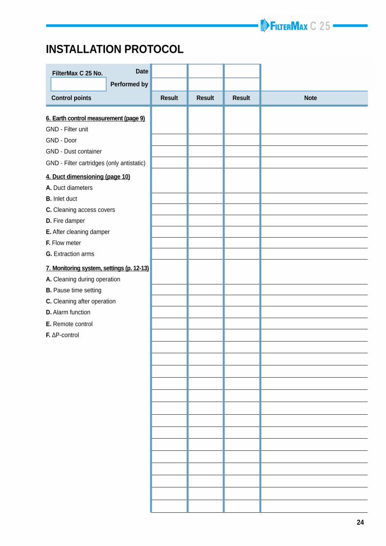
INSTALLATION PROTOCOLIf controls give results (for example measured values) whichdiffer much from earlier results, this must be understood as awarning signal and lead to more careful investigations.
Result Result Result Note
Performed by
Date
Control points
1. Delivery control
A. Missing components
B. Transport damage
2. Installation control (page 5)
A. Safe mounting / foundation
B. Fixing bolts / Traction forces
C. Weight FilterMax / collected dust
D. Screw fittings
E. Dust container
F. Filter cartridges
3. Compressed air connection (page 6)
A. Service valve
B. Filter regulator
C. Pressure 0,4 - 0,6 MPa (4 - 6 bar)
D. Dew point
E. Oil / Moisture
F. Cleaning compressed air connections
5. Electrical installation (page 6-8)
A. Overload protector
B. Safety switch
C. After cleaning damper
D. Fan
E. Y/D- Start
F. Extern START/STOP
G. Alarm
H. Activating, in/outputs
C 25
24
6. Earth control measurement (page 9)
GND - Filter unit
GND - Door
GND - Dust container
GND - Filter cartridges (only antistatic)
4. Duct dimensioning (page 10)
A. Duct diameters
B. Inlet duct
C. Cleaning access covers
D. Fire damper
E. After cleaning damper
F. Flow meter
G. Extraction arms
7. Monitoring system, settings (p. 12-13)
A. Cleaning during operation
B. Pause time setting
C. Cleaning after operation
D. Alarm function
E. Remote control
F. ∆P-control
INSTALLATION PROTOCOL
Result Result Result NoteControl points
FilterMax C 25 No.
Performed by
Date

C 25
FilterMax C 25 No.
ever
y 10
00 h
*ev
ery
2000
h *
ever
y 60
00 h
*
1. Dust container / Filter regulator
A. Empty the dust container (when 70 % full)
B. Water check filter regulator
C. Water check pressure tank
2. Pulse jet valves,function check
3. Remove dust,clean air room
4. Cleaning access cover, cleaning
5. Checking the filter cartridges
6. Earth control measurement (page 9)
A. GND - Filter unit
B. GND - Door
C. GND - Dust container
E. GND - Filter cartridges (support baskets, only on Poly Web antistatic filter)
8. Replacing the filter cartridges(page 17)
9. Check that the cables not aredamaged or connected incorrectly
Control points Result Result Result Result Result
Performed by
Date
Operating hours
25
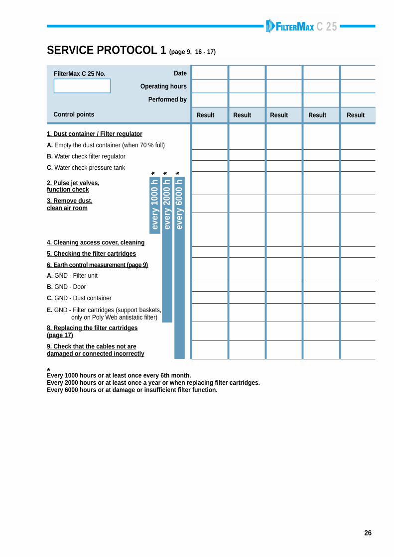
SERVICE PROTOCOL 1 (page 9, 16 - 17)
*Every 1000 hours or at least once every 6th month.Every 2000 hours or at least once a year or when replacing filter cartridges.Every 6000 hours or at damage or insufficient filter function.
C 25
FilterMax C 25 No.
ever
y 10
00 h
*ev
ery
2000
h *
ever
y 60
00 h
*
1. Dust container / Filter regulator
A. Empty the dust container (when 70 % full)
B. Water check filter regulator
C. Water check pressure tank
2. Pulse jet valves,function check
3. Remove dust,clean air room
4. Cleaning access cover, cleaning
5. Checking the filter cartridges
6. Earth control measurement (page 9)
A. GND - Filter unit
B. GND - Door
C. GND - Dust container
E. GND - Filter cartridges (support baskets, only on Poly Web antistatic filter)
8. Replacing the filter cartridges(page 17)
9. Check that the cables not aredamaged or connected incorrectly
Control points Result Result Result Result Result
Performed by
Date
Operating hours
26
SERVICE PROTOCOL 1 (page 9, 16 - 17)
*Every 1000 hours or at least once every 6th month.Every 2000 hours or at least once a year or when replacing filter cartridges.Every 6000 hours or at damage or insufficient filter function.
C 25
27
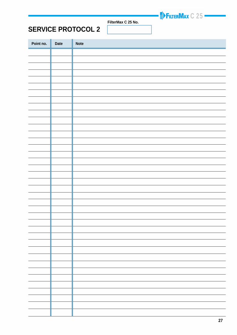
SERVICE PROTOCOL 2FilterMax C 25 No.
Point no. Date Note
C 25