Embed Size (px)
Citation preview
Instruction Manual• Authorized Electricians
KACO blueplanet 32.0 TL3
KACO blueplanet 40.0 TL3
KACO blueplanet 50.0 TL3


Installation Instructions KACO blueplanet 32.0 TL3 / 40.0 TL3 / 50.0 TL3 Page 3
Installation Instructions
for authorized electricians
Contents
1 General Information ................................. 4
1.1 About this document ............................................4
1.2 Layout of Instructions ...........................................4
2 Safety ......................................................... 5
2.1 Intended use ............................................................6
2.2 Protection features ................................................6
2.3 Standards and regulations ..................................6
3 Description ................................................ 7
3.1 Mode of Operation ................................................ 7
3.2 Description of the unit ....................................... 7
4 Technical Data ......................................... 10
4.1 Electrical Data ........................................................ 10
4.2 Mechanical ............................................................... 11
5 Transportation and Delivery ...................12
5.1 Delivery .....................................................................12
5.2 Transportation ........................................................12
6 Mounting the inverter .............................13
6.1 Installing and securing the inverter ............. 15
6.2 Installing the DC and AC isolator switches . 16
7 Installing the inverter ..............................17
7.1 Opening the connection area ...........................17
7.2 Drilling holes for electrical and interface connections ..........................................17
7.3 Making the electrical connection ................... 18
7.4 Connecting the interfaces..................................21
7.5 Sealing the connection area ............................25
7.6 Starting up the inverter......................................26
8 Confi guration and Operation ................. 27
8.1 Controls .................................................................... 27
8.2 Initial commissioning .........................................30
8.3 Menu structure ......................................................30
8.4 Monitoring the inverter .....................................36
8.5 Performing a software update ........................38
9 Maintenance/Troubleshooting .............. 39
9.1 Visual inspection...................................................39
9.2 External cleaning ..................................................39
9.3 Shutting down for maintenance and troubleshooting ....................................................39
9.4 Faults ........................................................................ 40
9.5 "Fault" messages on the display/LED ............42
10 Service ...................................................... 47
11 Shutdown/Disassembly .......................... 47
11.1 Shutting down the inverter ..............................47
11.2 Uninstalling the inverter ................................... 48
11.3 Dismantling the inverter................................... 48
12 Recycling and disposal ...........................48
13 Appendix .................................................49
General Information
Page 4 Installation Instructions KACO blueplanet 32.0 TL3 / 40.0 TL3 / 50.0 TL3
1 General Information
1.1 About this document
WARNING
Improper handling of the inverter can be hazardous
› You must read and understand the operating instructions before you can install and use the inverter
safely.
1.1.1 Other applicable documents
During installation, observe all assembly and installation instructions for components and other parts of the system.
These instructions also apply to the equipment, related components and other parts of the system.
1.1.2 Storing the documents
These instructions and other documents must be stored near the system and be available at all times.
1.2 Layout of Instructions
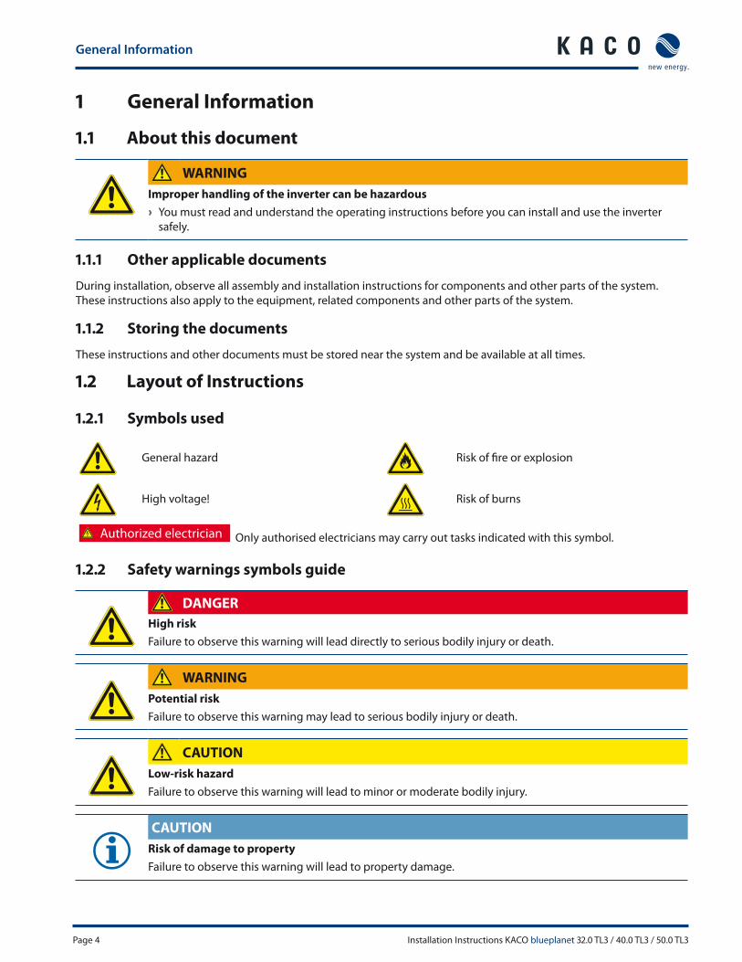
1.2.1 Symbols used
General hazard Risk of fi re or explosion
High voltage! Risk of burns
Authorized electrician Only authorised electricians may carry out tasks indicated with this symbol.
1.2.2 Safety warnings symbols guide
DANGER
High risk
Failure to observe this warning will lead directly to serious bodily injury or death.
WARNING
Potential risk
Failure to observe this warning may lead to serious bodily injury or death.
CAUTION
Low-risk hazard
Failure to observe this warning will lead to minor or moderate bodily injury.
CAUTION
Risk of damage to property
Failure to observe this warning will lead to property damage.
Safety
Installation Instructions KACO blueplanet 32.0 TL3 / 40.0 TL3 / 50.0 TL3 Page 5
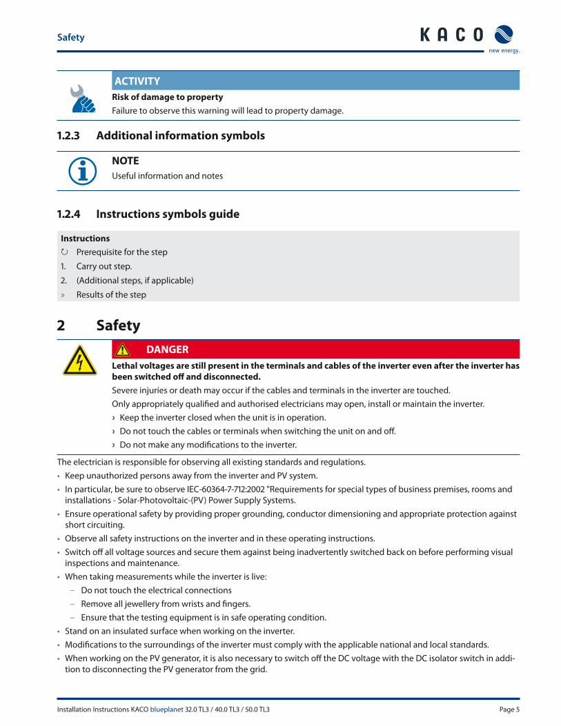
ACTIVITY
Risk of damage to property
Failure to observe this warning will lead to property damage.
1.2.3 Additional information symbols
NOTE
Useful information and notes
1.2.4 Instructions symbols guide
Instructions
↻ Prerequisite for the step
1. Carry out step.
2. (Additional steps, if applicable)
» Results of the step
2 Safety
DANGER
Lethal voltages are still present in the terminals and cables of the inverter even after the inverter has
been switched off and disconnected.
Severe injuries or death may occur if the cables and terminals in the inverter are touched.
Only appropriately qualifi ed and authorised electricians may open, install or maintain the inverter.
› Keep the inverter closed when the unit is in operation.
› Do not touch the cables or terminals when switching the unit on and off .
› Do not make any modifi cations to the inverter.
The electrician is responsible for observing all existing standards and regulations.
• Keep unauthorized persons away from the inverter and PV system.
• In particular, be sure to observe IEC-60364-7-712:2002 "Requirements for special types of business premises, rooms and
installations - Solar-Photovoltaic-(PV) Power Supply Systems.
• Ensure operational safety by providing proper grounding, conductor dimensioning and appropriate protection against
short circuiting.
• Observe all safety instructions on the inverter and in these operating instructions.
• Switch off all voltage sources and secure them against being inadvertently switched back on before performing visual
inspections and maintenance.
• When taking measurements while the inverter is live:
– Do not touch the electrical connections
– Remove all jewellery from wrists and fi ngers.
– Ensure that the testing equipment is in safe operating condition.
• Stand on an insulated surface when working on the inverter.
• Modifi cations to the surroundings of the inverter must comply with the applicable national and local standards.
• When working on the PV generator, it is also necessary to switch off the DC voltage with the DC isolator switch in addi-
tion to disconnecting the PV generator from the grid.
Safety
Page 6 Installation Instructions KACO blueplanet 32.0 TL3 / 40.0 TL3 / 50.0 TL3
2.1 Intended use
The ISO-inverter converts clean renewable DC energy into AC energy for export into the utility. The inverter was designed
in accordance with UL 1741, CSA-C22.2 No. 107.1.01 and the NFPA 70. Authorized personnel who are qualifi ed for the VAC
and VDC voltage ratings are the only people who should install or maintain this equipment. Lethal hazards exist which
may result in serious injury.
Operate the inverter only with a permanent connection to the public power grid.
Any other or additional use of the device is deemed improper. This includes:
• Mobile use,
• Use in rooms where there is a risk of explosion,
• Use in rooms where the humidity is higher than 95%,
• Operation outside of the specifi cations intended by the manufacturer,
• Standalone mode
2.2 Protection features
For your safety, the following monitoring and protective functions are integrated into blueplanet inverters:
• Overvoltage conductors/varistors to protect the power semiconductors from high-energy transients on the grid and
generator side,
• Temperature monitoring of the heat sink,
• EMC fi lters to protect the inverter from high-frequency grid interference,
• Grid-side grounded varistors to protect the inverter against burst and surge pulses,
• Islanding detection according to IEEE 1547
2.3 Standards and regulations
Electrical conformity according to U.S., Canadian and international safety operating standards and code
requirements:
• UL 1741-2nd Ed 2010
• NEC (2011)
• CSA 22.2 No. 107-1:2001 Rev 2011
• IEEE Std. 1547-2003
• IEEE Std. 1547.1-2005
• FCC Part 15 Class B
• NFPA 70
• Wiring method is accordance with the National Electrical Code ANSI/NFPA 70
• Directive concerning Electromagnetic Compatibility with Class B (Council Directive 2004/108/EC)
• Low Voltage Directive (Council Directive 2006/95/EC)
• The Inverter has a on-board overcurrent protection for DC circuit.
• The inverter has no internal overcurrent protection for AC circuit. The overcurrent protection for AC circuit must be
installed by authorized electricians.
• The Inverter has a over-temperature and anti-islanding protection.

Description
Installation Instructions KACO blueplanet 32.0 TL3 / 40.0 TL3 / 50.0 TL3 Page 7
3 Description
3.1 Mode of Operation
The inverter converts the DC voltage generated by the PV modules into AC voltage and feeds it into the grid. The feed-
in process begins when there is suffi cient sunlight and a specifi c minimum voltage is present in the inverter. If, as it gets
dark, the voltage drops below the minimum voltage value, the feed-in operation ends and the inverter switches off .
3.2 Description of the unit
3.2.1 Inverter as part of a PV system
3.2.1.1 System layout
KWhKWh
PV generator PV generator
Inverter with
DC/AC isolator switches
Inverter with
DC/AC isolator switches
Fuse Fuse
Load
Feed-in meterReference
counter
Main switch
Grid connection point
Selective main
switch
Figure 1: Circuit diagram of a system with two inverters

Description
Page 8 Installation Instructions KACO blueplanet 32.0 TL3 / 40.0 TL3 / 50.0 TL3
3.2.1.2 Summary of the components
PV generator
The PV generator, i.e. the PV modules, converts the radiant energy of sunlight into electrical energy.
DC terminal point
Options for parallel connections of several generator strings:
• To a DC terminal point between the DC generator and inverter,
• directly on the inverter (one terminal per 1-line is included on the inverter for each device model (with one or three MPP
trackers)),
• directly to the PV generator with a positive and negative lead to the inverter.
DC isolator switch (2-pole (Model M1 devices) / 6-pole (Model M3 devices))
Use the DC isolator switch to disconnect the inverter from all power sources on the PV generator side.
AC isolator switch (3-pole)
Use the AC isolator switch to disconnect the inverter from all power sources on the grid side.
Feed-in meter
The feed-in meter is to be specifi ed and installed by the power supply company. Some power supply companies also
allow the installation of your own calibrated meters.
3.2.2 Inverter diagram
1
2
3
6
7
8
Figure 2: Inverter diagram
Key
1 Upper housing cover 6 Control panel
2 Doors 7 Fan cover
3 Cover for the connection area 8 Side housing cover
4 AC isolator switch 9 Door locks
5 DC isolator switch
4
5
9
9
Description
Installation Instructions KACO blueplanet 32.0 TL3 / 40.0 TL3 / 50.0 TL3 Page 9
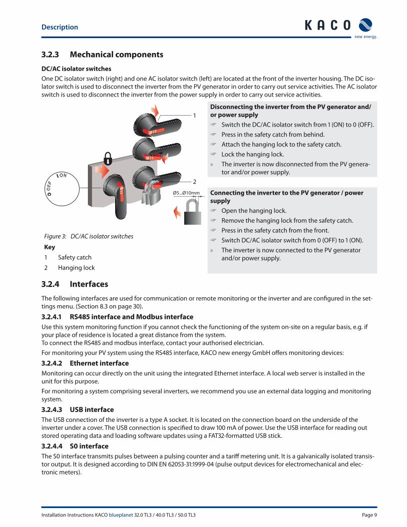
3.2.3 Mechanical components
DC/AC isolator switches
One DC isolator switch (right) and one AC isolator switch (left) are located at the front of the inverter housing. The DC iso-
lator switch is used to disconnect the inverter from the PV generator in order to carry out service activities. The AC isolator
switch is used to disconnect the inverter from the power supply in order to carry out service activities.
NOI
OOFF
OOFF
NOI
NOI
OOFF
NOI
OOFF
OOFF
I ON
Ø5...Ø10mm
N
1
2
Disconnecting the inverter from the PV generator and/
or power supply
Switch the DC/AC isolator switch from 1 (ON) to 0 (OFF).
Press in the safety catch from behind.
Attach the hanging lock to the safety catch.
Lock the hanging lock.
» The inverter is now disconnected from the PV genera-
tor and/or power supply.
Connecting the inverter to the PV generator / power
supply
Open the hanging lock.
Remove the hanging lock from the safety catch.
Press in the safety catch from the front.
Switch DC/AC isolator switch from 0 (OFF) to 1 (ON).
» The inverter is now connected to the PV generator
and/or power supply.
Figure 3: DC/AC isolator switches
Key
1 Safety catch
2 Hanging lock
3.2.4 Interfaces
The following interfaces are used for communication or remote monitoring or the inverter and are confi gured in the set-
tings menu. (Section 8.3 on page 30).
3.2.4.1 RS485 interface and Modbus interface
Use this system monitoring function if you cannot check the functioning of the system on-site on a regular basis, e.g. if
your place of residence is located a great distance from the system.
To connect the RS485 and modbus interface, contact your authorised electrician.
For monitoring your PV system using the RS485 interface, KACO new energy GmbH off ers monitoring devices:
3.2.4.2 Ethernet interface
Monitoring can occur directly on the unit using the integrated Ethernet interface. A local web server is installed in the
unit for this purpose.
For monitoring a system comprising several inverters, we recommend you use an external data logging and monitoring
system.
3.2.4.3 USB interface
The USB connection of the inverter is a type A socket. It is located on the connection board on the underside of the
inverter under a cover. The USB connection is specifi ed to draw 100 mA of power. Use the USB interface for reading out
stored operating data and loading software updates using a FAT32-formatted USB stick.
3.2.4.4 S0 interface
The S0 interface transmits pulses between a pulsing counter and a tariff metering unit. It is a galvanically isolated transis-
tor output. It is designed according to DIN EN 62053-31:1999-04 (pulse output devices for electromechanical and elec-
tronic meters).
Technical Data
Page 10 Installation Instructions KACO blueplanet 32.0 TL3 / 40.0 TL3 / 50.0 TL3
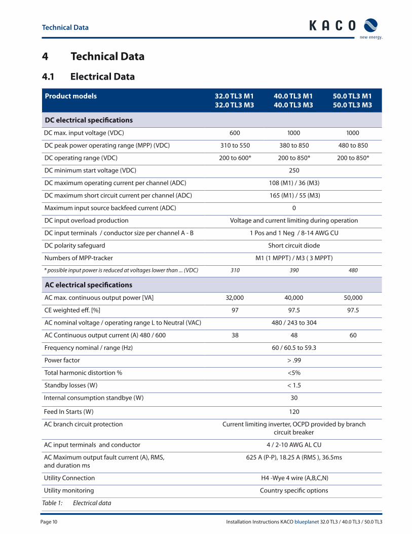
4 Technical Data
4.1 Electrical Data
Product models 32.0 TL3 M1
32.0 TL3 M3
40.0 TL3 M1
40.0 TL3 M3
50.0 TL3 M1
50.0 TL3 M3
DC electrical specifi cations
DC max. input voltage (VDC) 600 1000 1000
DC peak power operating range (MPP) (VDC) 310 to 550 380 to 850 480 to 850
DC operating range (VDC) 200 to 600* 200 to 850* 200 to 850*
DC minimum start voltage (VDC) 250
DC maximum operating current per channel (ADC) 108 (M1) / 36 (M3)
DC maximum short circuit current per channel (ADC) 165 (M1) / 55 (M3)
Maximum input source backfeed current (ADC) 0
DC input overload production Voltage and current limiting during operation
DC input terminals / conductor size per channel A - B 1 Pos and 1 Neg / 8-14 AWG CU
DC polarity safeguard Short circuit diode
Numbers of MPP-tracker M1 (1 MPPT) / M3 ( 3 MPPT)
* possible input power is reduced at voltages lower than ... (VDC) 310 390 480
AC electrical specifi cations
AC max. continuous output power [VA] 32,000 40,000 50,000
CE weighted eff . [%] 97 97.5 97.5
AC nominal voltage / operating range L to Neutral (VAC) 480 / 243 to 304
AC Continuous output current (A) 480 / 600 38 48 60
Frequency nominal / range (Hz) 60 / 60.5 to 59.3
Power factor > .99
Total harmonic distortion % <5%
Standby losses (W) < 1.5
Internal consumption standbye (W) 30
Feed In Starts (W) 120
AC branch circuit protection Current limiting inverter, OCPD provided by branch
circuit breaker
AC input terminals and conductor 4 / 2-10 AWG AL CU
AC Maximum output fault current (A), RMS,
and duration ms
625 A (P-P), 18.25 A (RMS ), 36.5ms
Utility Connection H4 -Wye 4 wire (A,B,C,N)
Utility monitoring Country specifi c options
Table 1: Electrical data

Technical Data
Installation Instructions KACO blueplanet 32.0 TL3 / 40.0 TL3 / 50.0 TL3 Page 11
PV system disconnect
Integrated AC/DC disconnect Yes
AC /DC disconnection means Rotary switch accessible from outside of enclosure
AC disconnection ratings 100 A VAC Break L1-L2-L3
AC LOTO Provision LOTO in OPEN
AC input terminals / conductor size L1-L2-L3 N PE / 4-10 AWG AL CU
DC disconnection ratings 150 A breaking positive and negative
DC Over current protection devices (OCPD) Not provided inside the inverter
DC LOTO Provision LOTO in OPEN
DC input terminals / conductor size per channel 1 Pos and 1 Neg / 6-24 AWG AL CU
Table 1: Electrical data
4.2 Mechanical
Mechanical and environmental specifi cations
Mechanical integration Ground mount
Enclosure construction Cast steel
Unit weight lbs / kg 381 / 173
Unit dimensions HxWxD In / mm 33 x 14 x 53.5/ 840 x 355 x 1360
Operating temp range (°F / °C) (-13 to 140 / -25 to 60) possible derating above 113 °F / 45 °C
Storage temp range (°F / °C) (-22 to 158 / -30 to 70)
Noise emissions <58 db(A)
Humidity % 0 to 95 non condensing
Enclosure rating Inverter / PV system disconnect NEMA 3R
Cooling Forced convection with variable speed fan
Altitude (ft / m) 8000 / 2400
Communications and user interface
User interface Graphical user interface with 3 LED status indicators
Connectivity Ethernet (Modbus (TCP IP)), USB, RS485, S0 output
Safety features and regulatory compliance
UL / IEEE / CSA / FCC UL 1741 2nd Ed 2010 / CSA C22.2No 107.1 /
IEEE 1547 / FCC Class B / UL1998
Fault signal relay Potential free normally open contact
Polarity safeguard Short circuit diode
CE conformity Yes
GFDI compliant with NEC 690.35 for use with
ungrounded PV system arrays.
UL1741 listed for residual ground fault current isolation monitor
and interrupter function.
Table 2: Mechanical data
Transportation and Delivery
Page 12 Installation Instructions KACO blueplanet 32.0 TL3 / 40.0 TL3 / 50.0 TL3
5 Transportation and Delivery
5.1 Delivery
Every inverter leaves our factory in proper electrical and mechanical condition. Special packaging ensures that the units
are transported safely. The shipping company is responsible for any transport damage that occurs.
5.1.1 Scope of delivery
• Inverters
• Housing covers: Cover plates right and left, cover
• Installation kit
• DC and AC isolator switches
• Connection set
• Documentation
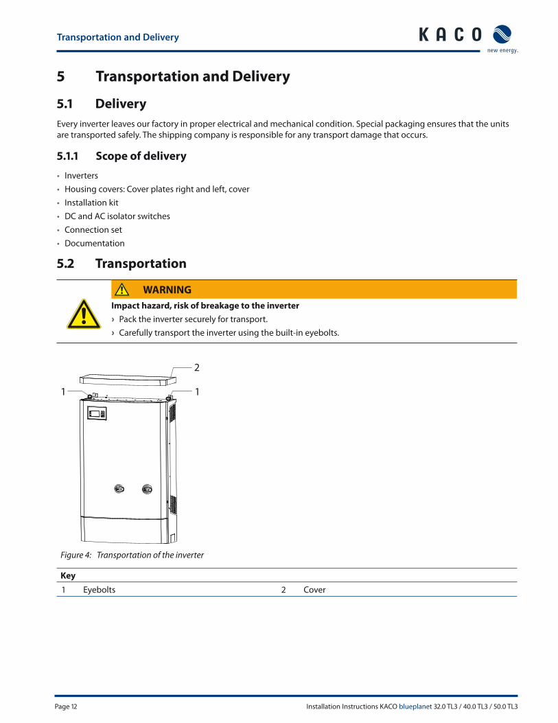
5.2 Transportation
WARNING
Impact hazard, risk of breakage to the inverter
› Pack the inverter securely for transport.
› Carefully transport the inverter using the built-in eyebolts.
1
2
1
Figure 4: Transportation of the inverter
Key
1 Eyebolts 2 Cover

Mounting the inverter
Installation Instructions KACO blueplanet 32.0 TL3 / 40.0 TL3 / 50.0 TL3 Page 13
6 Mounting the inverter
DANGER
Risk of fatal injury from fi re or explosions
Fire caused by fl ammable or explosive materials in the vicinity of the inverter can lead to serious injuries.
› Do not mount the inverter in an area at risk of explosion or in the vicinity of highly fl ammable materials.
CAUTION
Risk of burns from hot housing components.
Coming into contact with the housing can cause burns.
› Mount the inverter so that it cannot be touched unintentionally.
Installation space
• As dry as possible, climate-controlled, with the waste heat dissipated away from the inverter,
• Unobstructed air circulation,
• When installing the unit in a control cabinet, provide forced ventilation so that the heat is suffi ciently dissipated,
• Close to the ground, accessible from the front and sides without requiring additional resources
• Protected from direct sunlight and moisture (rain) in outdoor areas,
• For easy operation, ensure during installation that the display is slightly below eye level.
Wall
• With suffi cient load-bearing capacity,
• Accessible for installation and maintenance,
• Made from heat-resistant material (up to 194°F/90 °C),
• Flame resistant,
• Minimum clearances to be observed during assembly: see Figure 6 on page 14 and Figure 7 on page 15.
NOTE
Access by maintenance personnel for service
Any additional costs arising from unfavourable structural or mounting conditions shall be billed to the
customer.
CAUTION
Property damage due to gases that have an abrasive eff ect on surfaces when they come into con-
tact with
ambient humidity caused by weather conditions
The inverter housing can be severely damaged by gases (ammonia, sulphur, etc.) if it comes into
contact with ambient humidity caused by weather conditions.
If the inverter is exposed to gases, it must be mounted so that it can be seen at all times.
› Perform regular visual inspections.
› Immediately remove any moisture from the housing.
› Take care to ensure suffi cient ventilation of the inverter.
› Immediately remove dirt, especially on vents.
› Failure to observe these warnings may lead to inverter damage which is not covered by the KACO new
energy GmbH manufacturer warranty.
Mounting the inverter
Page 14 Installation Instructions KACO blueplanet 32.0 TL3 / 40.0 TL3 / 50.0 TL3
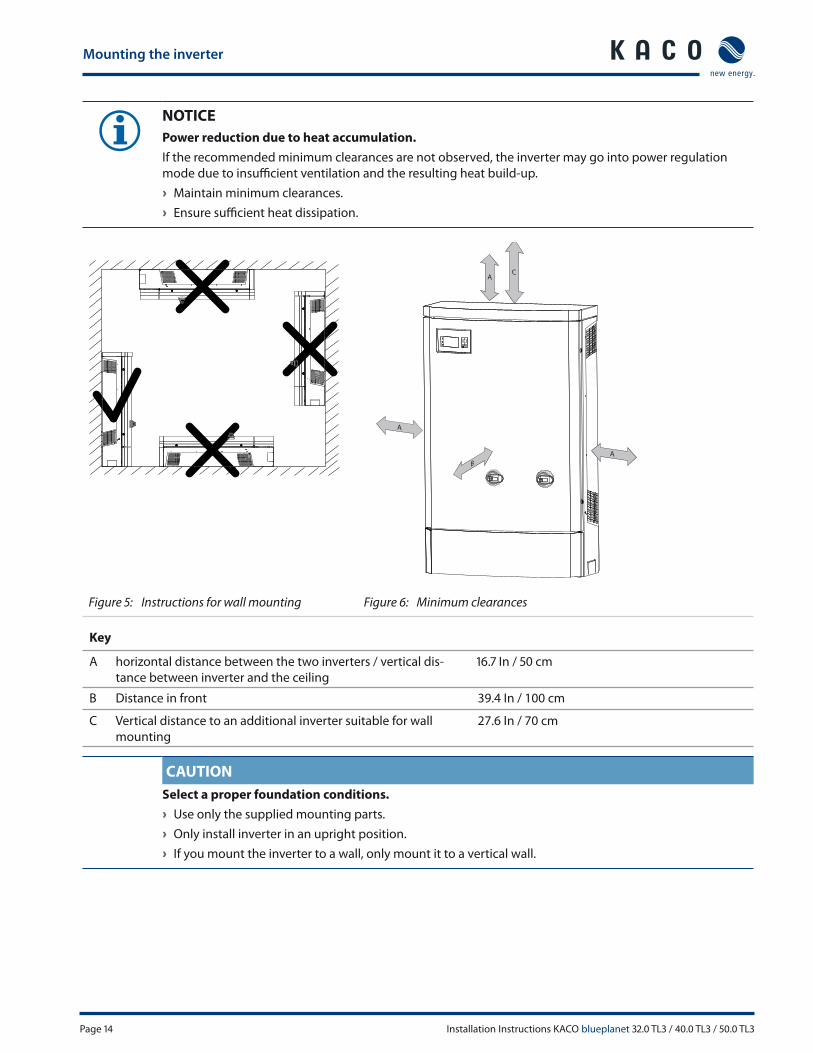
NOTICE
Power reduction due to heat accumulation.
If the recommended minimum clearances are not observed, the inverter may go into power regulation
mode due to insuffi cient ventilation and the resulting heat build-up.
› Maintain minimum clearances.
› Ensure suffi cient heat dissipation.
B
A
AC
A
Figure 5: Instructions for wall mounting Figure 6: Minimum clearances
Key
A horizontal distance between the two inverters / vertical dis-
tance between inverter and the ceiling
16.7 In / 50 cm
B Distance in front 39.4 In / 100 cm
C Vertical distance to an additional inverter suitable for wall
mounting
27.6 In / 70 cm
CAUTION
Select a proper foundation conditions.
› Use only the supplied mounting parts.
› Only install inverter in an upright position.
› If you mount the inverter to a wall, only mount it to a vertical wall.
Mounting the inverter
Installation Instructions KACO blueplanet 32.0 TL3 / 40.0 TL3 / 50.0 TL3 Page 15
CAUTION
Use suitable mounting parts.
› Use only the supplied mounting parts.
› Only install inverter in an upright position.
› If you mount the inverter to a wall, only mount it to a vertical wall.
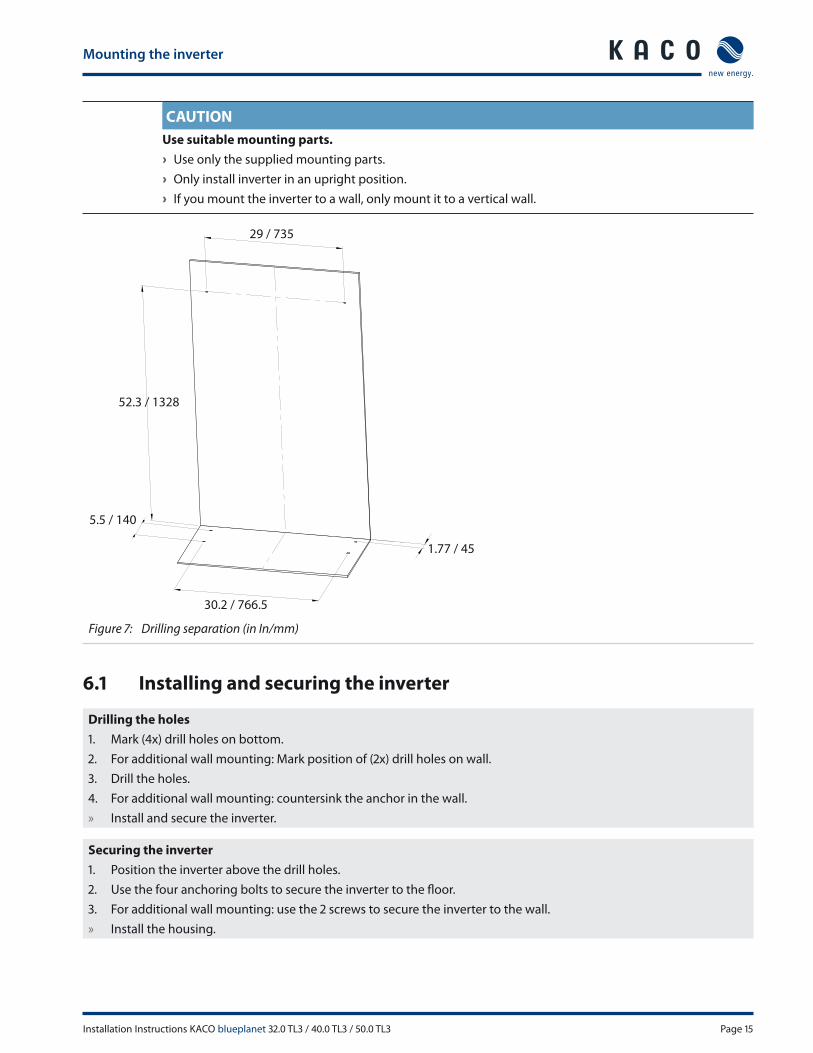
29 / 735
52.3 / 1328
5.5 / 140
30.2 / 766.5
1.77 / 45
Figure 7: Drilling separation (in In/mm)
6.1 Installing and securing the inverter
Drilling the holes
1. Mark (4x) drill holes on bottom.
2. For additional wall mounting: Mark position of (2x) drill holes on wall.
3. Drill the holes.
4. For additional wall mounting: countersink the anchor in the wall.
» Install and secure the inverter.
Securing the inverter
1. Position the inverter above the drill holes.
2. Use the four anchoring bolts to secure the inverter to the fl oor.
3. For additional wall mounting: use the 2 screws to secure the inverter to the wall.
» Install the housing.
Mounting the inverter
Page 16 Installation Instructions KACO blueplanet 32.0 TL3 / 40.0 TL3 / 50.0 TL3
6.2 Installing the DC and AC isolator switches
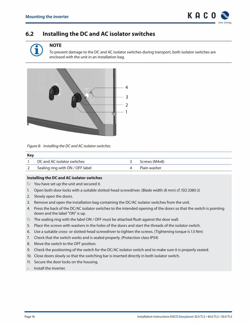
NOTE
To prevent damage to the DC and AC isolator switches during transport, both isolator switches are
enclosed with the unit in an installation bag.
Figure 8: Installing the DC and AC isolator switches
Key
1 DC and AC isolator switches 3 Screws (M4x8)
2 Sealing ring with ON / OFF label 4 Plain washer
Installing the DC and AC isolator switches
↻ You have set up the unit and secured it.
1. Open both door locks with a suitable slotted-head screwdriver. (Blade width (8 mm) cf. ISO 2380-2)
2. Slowly open the doors.
3. Remove and open the installation bag containing the DC/AC isolator switches from the unit.
4. Press the back of the DC/AC isolator switches to the intended opening of the doors so that the switch is pointing
down and the label "ON" is up.
↻ The sealing ring with the label ON / OFF must be attached fl ush against the door wall.
5. Place the screws with washers in the holes of the doors and start the threads of the isolator switch.
6. Use a suitable cross- or slotted-head screwdriver to tighten the screws. (Tightening torque is 1.5 Nm)
7. Check that the switch works and is sealed properly. (Protection class IP54)
8. Move the switch to the OFF position.
9. Check the positioning of the switch for the DC/AC isolator switch and to make sure it is properly seated.
10. Close doors slowly so that the switching bar is inserted directly in both isolator switch.
11. Secure the door locks on the housing.
» Install the inverter.
2
1
3
4
Installing the inverter
Installation Instructions KACO blueplanet 32.0 TL3 / 40.0 TL3 / 50.0 TL3 Page 17
7 Installing the inverter
DANGER
Lethal voltages are still present in the terminals and cables of the inverter even after the inverter has
been switched off and disconnected.
Severe injuries or death may occur if the cables and terminals in the inverter are touched.
Only appropriately qualifi ed and authorised electricians may open and install the inverter.
The inverter must be mounted in a fi xed position before being connected electrically.
› Observe all safety regulations and current technical connection specifi cations of the responsible power
supply company.
› Disconnect the AC and DC sides.
› Secure both sides against being inadvertently switched back on.
› Ensure that the AC and DC sides are completely isolated and voltage free.
› Connect the inverter only after the aforementioned steps have been taken.
NOTICE
The doors can only be opened by switching off both DC/AC isolator switches and then unlocking both
door latches.
7.1 Opening the connection area
Opening the connection area
↻ You have mounted the inverter.
↻ Switch the DC/AC isolator switches to OFF.
» Power has been disconnected from the unit.
1. Open both door locks with a suitable slotted-head screwdriver.
2. Slowly open the doors.
3. Remove the cover of the connection area.
» Make the electrical connection.
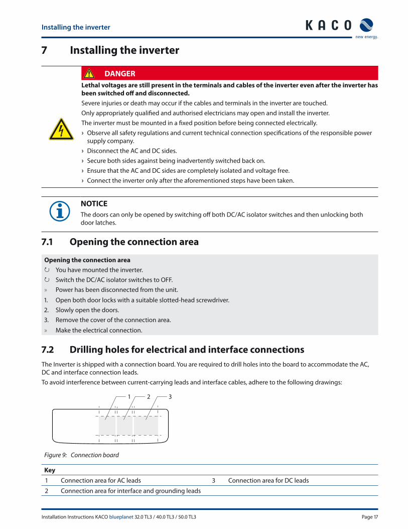
7.2 Drilling holes for electrical and interface connections
The Inverter is shipped with a connection board. You are required to drill holes into the board to accommodate the AC,
DC and interface connection leads.
To avoid interference between current-carrying leads and interface cables, adhere to the following drawings:
321
Figure 9: Connection board
Key
1 Connection area for AC leads 3 Connection area for DC leads
2 Connection area for interface and grounding leads

Installing the inverter
Page 18 Installation Instructions KACO blueplanet 32.0 TL3 / 40.0 TL3 / 50.0 TL3
7.3 Making the electrical connection
ACTIVITY
Cables to the AC and DC screw terminals must be re-tightened at regular intervals to the required torque.
Make the connection to the PV generator as well as the grid connection via the PCB terminals in the connection area of
the inverter. Note the following conductor cross-sections:
AC connection
(M1/M3)
DC connection
(M1)
DC connection
(M3)
Max. conductor cross-section without wire
sleeves
1 AWG / 50 mm² - 8 AWG / 10 mm²
Min. conductor cross-section with wire sleeves 3 AWG / 35 mm² - 8 AWG / 10 mm²
Max. conductor cross-section with cable shoe - 0 AWG / 70mm² with
M8 ring cable lug
-
Length of insulation to be stripped off 0.944 In / 24 mm 0.984 In / 25 mm 0.984 In / 25 mm
Tightening torque 2.5-4 Nm 2.5 Nm 2.5 Nm
Fuses
Overvoltage conductor Built-in, type II
3
21
L1 L2 L3 N GRY3~+N 277/480V 60Hz PV- PV+ L1 L2 L3 N GR
Y3~+N 277/480V 60Hz
3
21
+ I - + I -
PV2
+ I -
PV1 PV3
Figure 10: Electrical connection (M1 Model) Figure 11: Electrical connection (M3 Model)
Key
1 AC connection terminals 3 DC connection terminals
2 N; Ground, (HOT,GND)
7.3.1 Connecting the inverter to the power grid
The power connection wires are connected to the AC terminal on the left of the connection area (see Figure 10 on page
18).
DANGER
Risk of fatal injury due to electric shock
Severe injury or death will result if the live connections are touched.
› Switch off all power sources to the inverter before you insert the grid power cable into the unit.
› Make sure that the device is isolated from the public power supply and the system power supply before
starting work.
Installing the inverter
Installation Instructions KACO blueplanet 32.0 TL3 / 40.0 TL3 / 50.0 TL3 Page 19
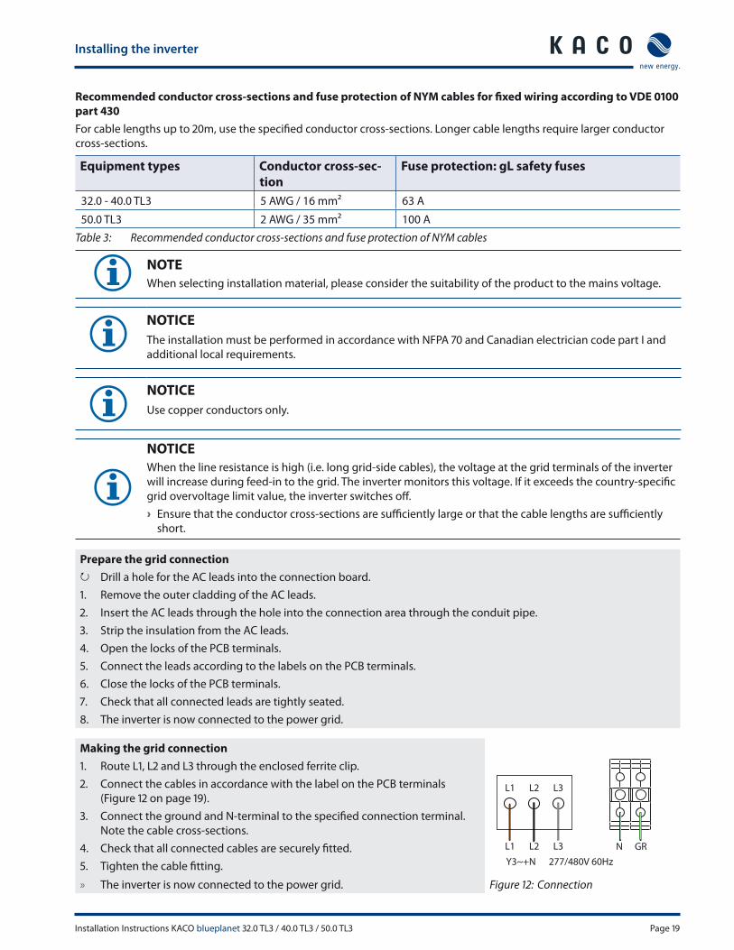
Recommended conductor cross-sections and fuse protection of NYM cables for fi xed wiring according to VDE 0100
part 430
For cable lengths up to 20m, use the specifi ed conductor cross-sections. Longer cable lengths require larger conductor
cross-sections.
Equipment types Conductor cross-sec-
tion
Fuse protection: gL safety fuses
32.0 - 40.0 TL3 5 AWG / 16 mm² 63 A
50.0 TL3 2 AWG / 35 mm² 100 A
Table 3: Recommended conductor cross-sections and fuse protection of NYM cables
NOTE
When selecting installation material, please consider the suitability of the product to the mains voltage.
NOTICE
The installation must be performed in accordance with NFPA 70 and Canadian electrician code part I and
additional local requirements.
NOTICE
Use copper conductors only.
NOTICE
When the line resistance is high (i.e. long grid-side cables), the voltage at the grid terminals of the inverter
will increase during feed-in to the grid. The inverter monitors this voltage. If it exceeds the country-specifi c
grid overvoltage limit value, the inverter switches off .
› Ensure that the conductor cross-sections are suffi ciently large or that the cable lengths are suffi ciently
short.
Prepare the grid connection
↻ Drill a hole for the AC leads into the connection board.
1. Remove the outer cladding of the AC leads.
2. Insert the AC leads through the hole into the connection area through the conduit pipe.
3. Strip the insulation from the AC leads.
4. Open the locks of the PCB terminals.
5. Connect the leads according to the labels on the PCB terminals.
6. Close the locks of the PCB terminals.
7. Check that all connected leads are tightly seated.
8. The inverter is now connected to the power grid.
Making the grid connection
1. Route L1, L2 and L3 through the enclosed ferrite clip.
2. Connect the cables in accordance with the label on the PCB terminals
(Figure 12 on page 19).
3. Connect the ground and N-terminal to the specifi ed connection terminal.
Note the cable cross-sections.
4. Check that all connected cables are securely fi tted.
5. Tighten the cable fi tting.
L1 L2
GRN
L3
L1 L2 L3
Y3~+N 277/480V 60Hz
» The inverter is now connected to the power grid. Figure 12: Connection
Installing the inverter
Page 20 Installation Instructions KACO blueplanet 32.0 TL3 / 40.0 TL3 / 50.0 TL3
7.3.2 Connecting the PV generator
Connect the PV generator on the right of the connection area (see Figure 10 on page 18).
DANGER
Risk of fatal injury due to contact voltages.
› During installation: Electrically disconnect the DC positive and DC negative from the protective earth
(PE).
Removing the plug connection without fi rst disconnecting the inverter from the PV generator may lead to
injuries and damage the inverter.
› Disconnect the inverter from the PV generator using the integrated DC isolator switch.
› Remove the plug connector.
NOTE
Connected PV modules must be dimensioned for the DC system voltage in accordance with IEC 61730
Class A, but at least for the value of the AC grid voltage
7.3.2.1 Before connecting
Ensure that there is no ground fault
1. Determine the DC voltage between the
– protective earth (PE) and the positive cable of the PV generator,
– protective earth (PE) and the negative cable of the PV generator
are identifi ed.
If stable voltages can be measured, there is a ground fault in the DC generator or its wiring. The ratio between the
measured voltages gives an indication as to the location of this fault.
2. Rectify any faults before taking further measurements.
3. Determine the electrical resistance between the
– protective earth (PE) and the positive cable of the PV generator,
– protective earth (PE) and the negative cable of the PV generator
are identifi ed.
In addition, ensure that the PV generator has a total insulation resistance of more than 2.0 mOhm, since the inverter will
not feed in if the insulation resistance is too low.
4. Rectify any faults before connecting the DC generator.
NOTICE
The threshold value from which the insulation monitor reports a fault can be set in the "Parameter" menu.
7.3.2.2 Connecting the PV generator
DANGER
Risk of fatal injury due to electric shock
Severe injury or death will result if the live connections are touched. When there is sunlight present, there is
DC voltage on the open ends of the DC cables.
› Do not touch the exposed ends of the cables.
› Avoid short circuits.

Installing the inverter
Installation Instructions KACO blueplanet 32.0 TL3 / 40.0 TL3 / 50.0 TL3 Page 21
Connecting the PV generator
1. Remove the outer cladding of the DC cables.
2. Route the DC cables into the connection
area.
3. Strip the insulation from the DC cables.
4. Connect the ends of the cables to the DC
connections per string (+/-).
5. Check that all connected cables are securely
fi tted.
» The inverter is connected to the
PV generator. PV - PV+ + I -
PV 1 PV 2 PV 3
+ I - + I -
Figure 13: PV connection (M1) Figure 14: PV connection (M3)
7.3.3 Grounding the housing
An optional grounding of the housing is possible at the grounding point provided for that purpose in the connection
area of the inverter. Please observe any national installation regulations in this regard.
Ground the housing of the inverter, if necessary, at the grounding point provided for that purpose in the connection area
of the inverter. It is marked with the symbol.
optional
Figure 15: Grounding point in the connection area
Grounding the housing
↻ Drill a hole for the grounding lead into the connection board.
1. Remove the outer cladding from the grounding lead.
2. Insert the grounding lead into the connection area through the conduit pipe.
3. Remove the insulation from the grounding lead.
4. Furnish the stripped lead with an M6 ring cable lug.
5. Screw the ring cable lug to the grounding point with an M6x16 screw.
6. Check for fi rm seating of the lead.
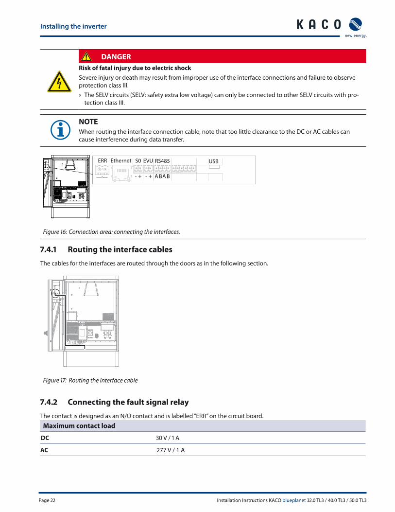
7.4 Connecting the interfaces
All interfaces are located on the connection circuit board in the upper area of the inverter door. Use the cable fi ttings pro-
vided and connect the connection cables to the circuit board.
Installing the inverter
Page 22 Installation Instructions KACO blueplanet 32.0 TL3 / 40.0 TL3 / 50.0 TL3
DANGER
Risk of fatal injury due to electric shock
Severe injury or death may result from improper use of the interface connections and failure to observe
protection class III.
› The SELV circuits (SELV: safety extra low voltage) can only be connected to other SELV circuits with pro-
tection class III.
NOTE
When routing the interface connection cable, note that too little clearance to the DC or AC cables can
cause interference during data transfer.
RS485 USBEVUS0ERR Ethernet
BA BA- + - +
Figure 16: Connection area: connecting the interfaces.
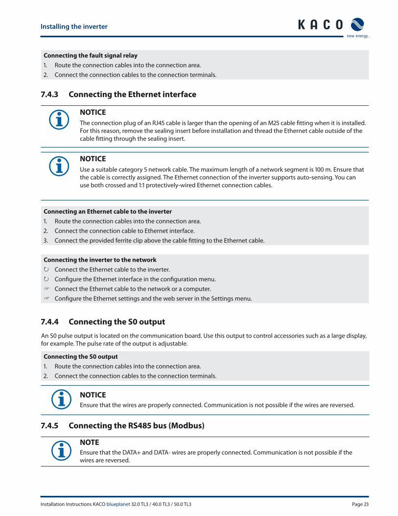
7.4.1 Routing the interface cables
The cables for the interfaces are routed through the doors as in the following section.
Figure 17: Routing the interface cable
7.4.2 Connecting the fault signal relay
The contact is designed as an N/O contact and is labelled “ERR” on the circuit board.
Maximum contact load
DC 30 V / 1 A
AC 277 V / 1 A
Installing the inverter
Installation Instructions KACO blueplanet 32.0 TL3 / 40.0 TL3 / 50.0 TL3 Page 23
Connecting the fault signal relay
1. Route the connection cables into the connection area.
2. Connect the connection cables to the connection terminals.
7.4.3 Connecting the Ethernet interface
NOTICE
The connection plug of an RJ45 cable is larger than the opening of an M25 cable fi tting when it is installed.
For this reason, remove the sealing insert before installation and thread the Ethernet cable outside of the
cable fi tting through the sealing insert.
NOTICE
Use a suitable category 5 network cable. The maximum length of a network segment is 100 m. Ensure that
the cable is correctly assigned. The Ethernet connection of the inverter supports auto-sensing. You can
use both crossed and 1:1 protectively-wired Ethernet connection cables.
Connecting an Ethernet cable to the inverter
1. Route the connection cables into the connection area.
2. Connect the connection cable to Ethernet interface.
3. Connect the provided ferrite clip above the cable fi tting to the Ethernet cable.
Connecting the inverter to the network
↻ Connect the Ethernet cable to the inverter.
↻ Confi gure the Ethernet interface in the confi guration menu.
Connect the Ethernet cable to the network or a computer.
Confi gure the Ethernet settings and the web server in the Settings menu.
7.4.4 Connecting the S0 output
An S0 pulse output is located on the communication board. Use this output to control accessories such as a large display,
for example. The pulse rate of the output is adjustable.
Connecting the S0 output
1. Route the connection cables into the connection area.
2. Connect the connection cables to the connection terminals.
NOTICE
Ensure that the wires are properly connected. Communication is not possible if the wires are reversed.
7.4.5 Connecting the RS485 bus (Modbus)
NOTE
Ensure that the DATA+ and DATA- wires are properly connected. Communication is not possible if the
wires are reversed.
Installing the inverter
Page 24 Installation Instructions KACO blueplanet 32.0 TL3 / 40.0 TL3 / 50.0 TL3
NOTICE
Diff erent manufacturers do not always interpret the standard on which the RS485 protocol is based in the
same way. Note that the wire designations (DATA- and DATA+) for wires A and B may vary from one manu-
facturer to another.
NOTICE
Calculating effi ciency by measuring the current and voltage values can lead to misleading results due to
the tolerances of the measurement devices. The sole purpose of these measured values is to monitor the
basic operation of the system.
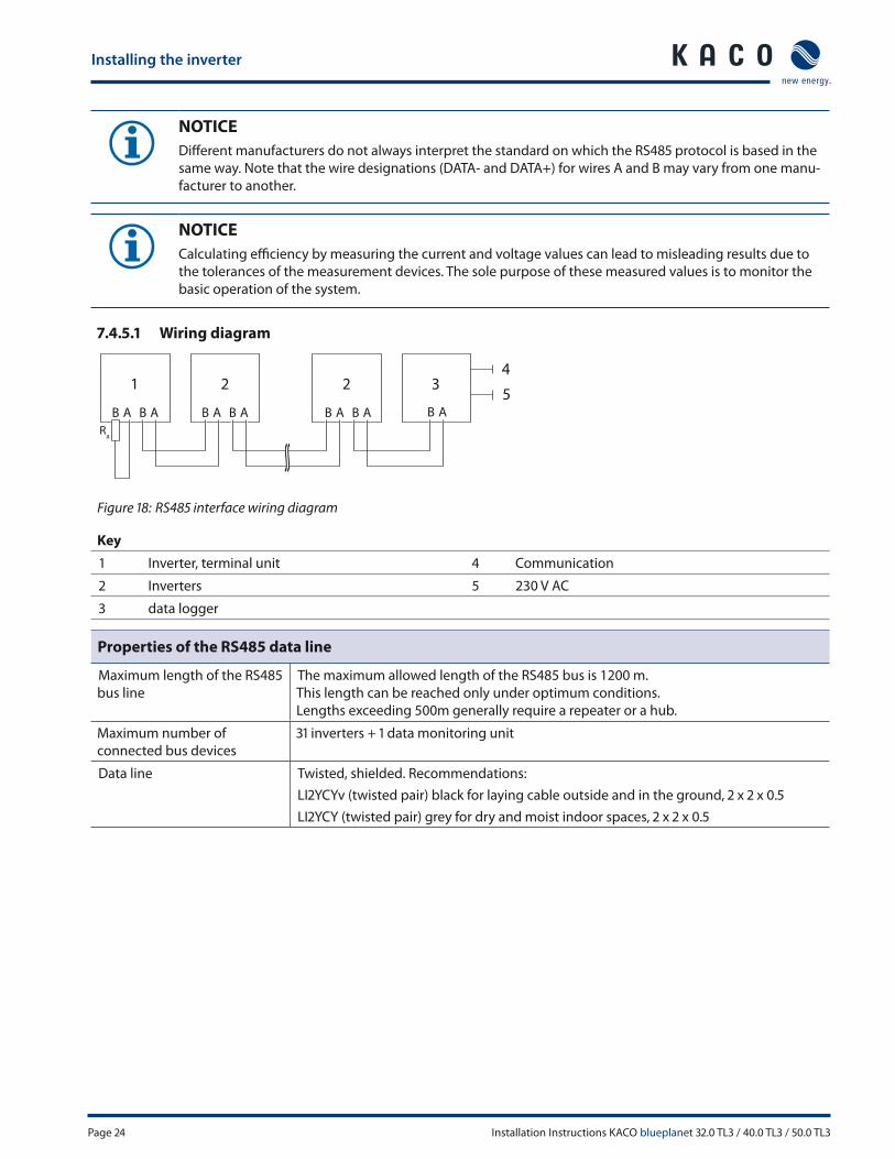
7.4.5.1 Wiring diagram
1 22 34
5
Figure 18: RS485 interface wiring diagram
Key
1 Inverter, terminal unit 4 Communication
2 Inverters 5 230 V AC
3 data logger
Properties of the RS485 data line
Maximum length of the RS485
bus line
The maximum allowed length of the RS485 bus is 1200 m.
This length can be reached only under optimum conditions.
Lengths exceeding 500m generally require a repeater or a hub.
Maximum number of
connected bus devices
31 inverters + 1 data monitoring unit
Data line Twisted, shielded. Recommendations:
LI2YCYv (twisted pair) black for laying cable outside and in the ground, 2 x 2 x 0.5
LI2YCY (twisted pair) grey for dry and moist indoor spaces, 2 x 2 x 0.5

Installing the inverter
Installation Instructions KACO blueplanet 32.0 TL3 / 40.0 TL3 / 50.0 TL3 Page 25
Connecting the RS485 bus
To prevent interference during data transmission:
• Observe the wire pairing when connecting DATA+ and DATA- (see Figure 19 on page
25)
• Do not install RS485 bus lines in the vicinity of live DC/AC cables.
1. Route the connection cables into the connection area.
2. Connect the connection cables to the corresponding connection terminals (see Figure
16 on page 22).
3. The following must be connected to all inverters and to the data monitor unit in the
same way:
– Wire A (-) with wire A (-) and
– Wire B (+) with wire B (+) (see Figure 18 on page 24)
4. Activate the terminating resistor on the terminal unit.
Figure 19: Assignment of
twisted-pair
wires
NOTICE
When using the RS485 bus system, assign a unique address to every bus device (inverter, sensor) and ter-
minate the terminal units (see the “Settings” menu) .
7.4.5.2 activate the terminating resistor in the settings menu
1. Open the menu.
2. Select "Settings"/"Interface."
3. Activate terminating resistor in the "Bus termination" menu entry.
4. Confi rm with "OK".
NOTE
The connection plug of an RJ45 cable is larger than the opening of an M25 cable fi tting when it is installed.
For this reason, remove the sealing insert before installation and thread the Ethernet cable outside of the
cable fi tting through the sealing insert.
7.5 Sealing the connection area
↻ All connections have been installed by specialists.
↻ All plug connections have been checked to ensure they are secure.
5. Put on the lid for the connection area.
6. Check the positioning of the switch for the DC/AC isolator switch and to make sure it is properly seated.
7. Close doors slowly so that the switching bar is inserted directly in both isolator switch.
8. Secure the door with both door locks.
» Start up the inverter.

Installing the inverter
Page 26 Installation Instructions KACO blueplanet 32.0 TL3 / 40.0 TL3 / 50.0 TL3
7.6 Starting up the inverter
DANGER
Lethal voltages are still present in the terminals and cables of the inverter even after the inverter
has been switched off and disconnected.
Severe injuries or death may occur if the cables and terminals in the inverter are touched.
Only appropriately qualifi ed and authorised electricians may start up the inverter.
7.6.1 Switching on the inverter
↻ The inverter has been mounted and electrically installed.
↻ The PV generator supplies a voltage above the confi gured start voltage.
1. Connect the grid voltage using the external circuit breakers.
2. Connect the PV generator using DC isolator switch (OFF → ON).
» The inverter begins to operate.
» During the initial start-up: Follow the instructions of the New Connection Wizard.
Configuration and Operation
Installation Instructions KACO blueplanet 32.0 TL3 / 40.0 TL3 / 50.0 TL3 Page 27
8 Confi guration and Operation
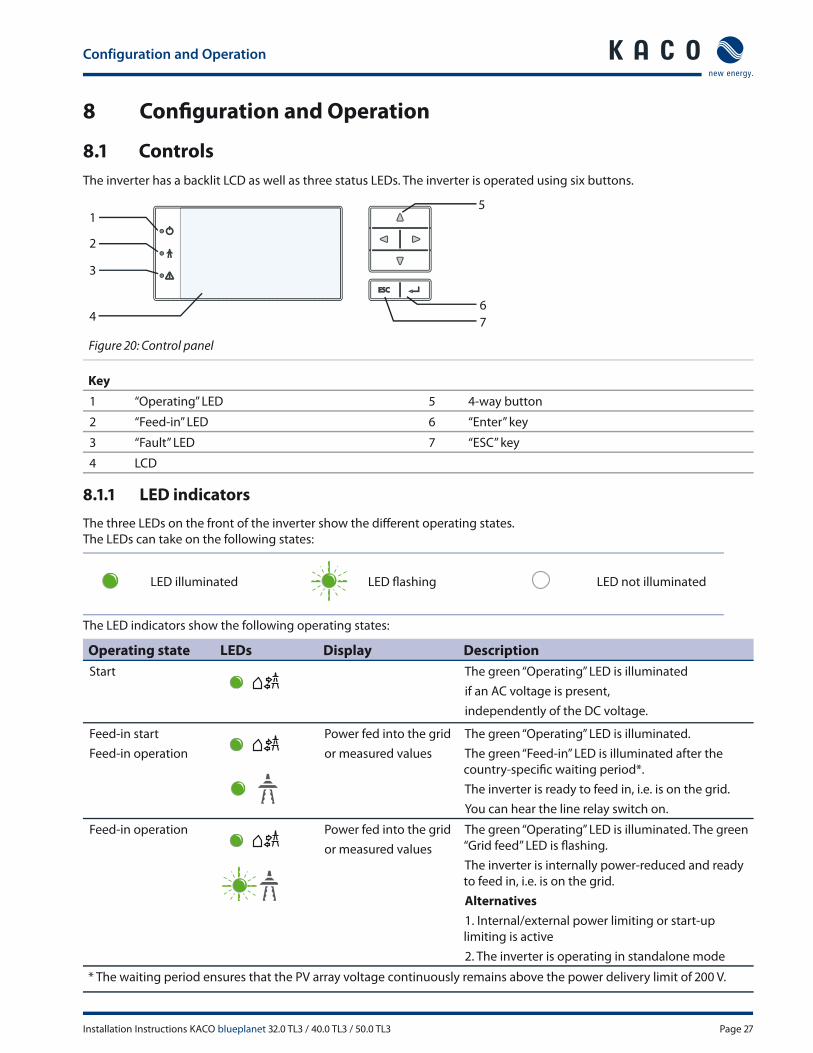
8.1 Controls
The inverter has a backlit LCD as well as three status LEDs. The inverter is operated using six buttons.
1
2
3
4
5
6
7
Figure 20: Control panel
Key
1 “Operating” LED 5 4-way button
2 “Feed-in” LED 6 “Enter” key
3 “Fault” LED 7 “ESC” key
4 LCD
8.1.1 LED indicators
The three LEDs on the front of the inverter show the diff erent operating states.
The LEDs can take on the following states:
LED illuminated LED fl ashing LED not illuminated
The LED indicators show the following operating states:
Operating state LEDs Display Description
Start The green “Operating” LED is illuminated
if an AC voltage is present,
independently of the DC voltage.
Feed-in start
Feed-in operation
Power fed into the grid
or measured values
The green “Operating” LED is illuminated.
The green “Feed-in” LED is illuminated after the
country-specifi c waiting period*.
The inverter is ready to feed in, i.e. is on the grid.
You can hear the line relay switch on.
Feed-in operation Power fed into the grid
or measured values
The green “Operating” LED is illuminated. The green
“Grid feed” LED is fl ashing.
The inverter is internally power-reduced and ready
to feed in, i.e. is on the grid.
Alternatives
1. Internal/external power limiting or start-up
limiting is active
2. The inverter is operating in standalone mode
* The waiting period ensures that the PV array voltage continuously remains above the power delivery limit of 200 V.

Configuration and Operation
Page 28 Installation Instructions KACO blueplanet 32.0 TL3 / 40.0 TL3 / 50.0 TL3
Operating state LEDs Display Description
Non-feed-in
operation
Status message The display shows the corresponding message.
Voltage Fault message The display shows the corresponding message.
The red “Fault” LED is illuminated.
8.1.2 Graphical display
The graphical display shows measured values and data and allows the confi guration of the inverter using a graphical
menu. In normal operation, the backlighting is switched off . As soon as you press one of the control buttons, the back-
lighting is activated. If no button is pressed for an adjustable period of time, it switches off again. You can also activate or
deactivate the backlighting permanently.
NOTICE
Depending on the tolerances of the measuring elements, the measured and displayed values are not
always the actual values. However, the measuring elements ensure maximum solar yield. Due to these
tolerances, the daily yields shown on the display may deviate from the values on the grid operator’s
feed-in meter by up to 15%.
After being switched on and after initial commissioning is complete, the inverter displays the start screen (the desktop). If
you are in the menu and do not touch the control buttons for two minutes, the inverter returns to the desktop.
For initial commissioning, see section 8.2 on page 30.
1
2
34
5
6
7
8
Figure 21: Desktop
Key
1 Current date 6 Status bar
2 Current power 7 Current time
3 Menu indicator 8 Feed-in indicator
4 Daily yield
5 Annual yield
8.1.3 Control buttons
The inverter is operated using the 4-way button and the OK and ESC buttons.

Configuration and Operation
Installation Instructions KACO blueplanet 32.0 TL3 / 40.0 TL3 / 50.0 TL3 Page 29
8.1.3.1 Desktop
Opening the menu
↻ The inverter is operating.
↻ The LCD is showing the desktop.
Press the right arrow button.
» The menu opens up over the desktop from left to right.
Displaying the daily output
↻ The inverter is operating.
↻ The LCD is showing the desktop.
Press the down arrow button.
» The LCD displays the daily yield in a diagram.
To return to the desktop, press any button.
8.1.3.2 Inverter menu
Selecting a menu item
↻ You have left the desktop. The inverter displays the menu.
Use the up and down arrow buttons.
Opening a menu item or a setting
Use the right arrow button and the OK button.
Jump to the next higher menu level/discard changes
Press the left arrow button or the ESC button.
Selecting an option
Use the right and left arrow buttons.
Changing an option/the value of an input fi eld
Use the up and down arrow buttons.
Saving changed settings
Press the OK button.
Configuration and Operation
Page 30 Installation Instructions KACO blueplanet 32.0 TL3 / 40.0 TL3 / 50.0 TL3
8.2 Initial commissioning
When started for the fi rst time, the inverter displays the confi guration assistant. It takes you through the settings neces-
sary for the initial start-up.
NOTE
After confi guration is completed, the confi guration assistant does not appear again when the inverter is
restarted. You can then change the country setting only in the password-protected parameter menu. The
other settings can still be changed in the Settings menu.
NOTICE
The sequence of the settings required for initial commissioning is preset in the confi guration assistant.
Initial confi guration
In order to select a setting, press the up and down buttons.
To select the next menu item, press the OK button.
To return to the most recently selected menu item, press the ESC button.
Set the required settings.
Press the OK button in the last menu item.
» You have completed the initial confi guration. The inverter begins to operate.
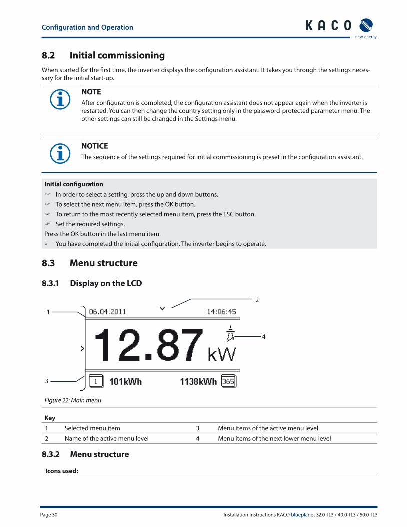
8.3 Menu structure
8.3.1 Display on the LCD
1
3
4
2
Figure 22: Main menu
Key
1 Selected menu item 3 Menu items of the active menu level
2 Name of the active menu level 4 Menu items of the next lower menu level
8.3.2 Menu structure
Icons used:

Configuration and Operation
Installation Instructions KACO blueplanet 32.0 TL3 / 40.0 TL3 / 50.0 TL3 Page 31
0 1 2 3 Menu level (0, 1, 2, 3) Password-protected menu
Display menu Submenu available
Option menu
Menu
level
Display/settings Action in this menu/meaning
Desktop Desktop Press the right arrow key.
0 1 2 30 “Measurements” menu Open the menu: Press the right arrow key or the OK key.
0 1 2 31 Generator Displays the DC-side voltage, amperage and power.
0 1 2 31 Grid Displays the AC-side voltage, amperage and power.
41 2 31 Power controlDisplays the current value of the external
power limitation by the grid operator.
41 2 31 cos-phi Indicates the status of the reactive power control.
0 1 2 31 Unit temperature Displays the temperature in the inverter housing.
0 1 2 31 Yield counterDisplays the yield in kWh.
Reset the counter using the “Reset” key.
0 1 2 31 Yield today Displays the cumulative yield for the current day.
0 1 2 31 Total yield Displays the total yield up to now.
0 1 2 31 CO2 savings Displays the calculated CO
2savings (in kg).
0 1 2 31 Oper. hours counterDisplays the duration of operation in hours.
Reset the counter using the “Reset” key.
0 1 2 31 Oper. time today Displays the duration of operation on the current day.
0 1 2 31 Total op. time Displays the total operating time.
0 1 2 31 Log data view Open the menu: Press the right arrow key or
the OK key.
0 1 2 32 Daily view
Displays the recorded operating data graphically.
1. Select the measured value to be displayed.
Supported measured values:
• Grid power P(grid)
• DC power per string P(PV) 1-2
• DC voltage per string U(PV) 1-2
• Unit temperature
2. Select a date.
3. Press the OK key.
» The display shows the selected data.
Press any key to return to the previous menu.

Configuration and Operation
Page 32 Installation Instructions KACO blueplanet 32.0 TL3 / 40.0 TL3 / 50.0 TL3
Menu
level
Display/settings Action in this menu/meaning
0 1 2 32 Monthly view
Displays the recorded operating data graphically.
1. Select a date.
2. Press the OK key.
» The display shows the selected data.
Press any key to return to the previous menu.
0 1 2 32 Yearly view
Displays the recorded operating data graphically.
1. Select a date.
2. Press the OK key.
» The display shows the selected data.
Press any key to return to the previous menu.
41 2 32 CSV log data Open the menu: Press the right arrow button or the OK button.
41 2 33 Decimal separator Select decimal sign for export of saved operating data.
0 1 2 32 Save to USB
In this menu, you can export the saved operating data to a
connected USB storage device.
↻ You have connected a USB storage device to the inverter.
1. Select the data to be exported (year, month or day) with the 4-way
key.
2. Press the OK key.
» The inverter writes the data to the USB storage device.
0 1 2 30 “Settings” menu Open the menu: Press the right arrow key or
the OK key.
0 1 2 31 Language Select the desired language for the user interface.
0 1 2 31 Defi ne total yield
You set the total yield to a freely selectable value, for example, when you
have received a replacement unit and want to continue the recording
from the present value.
Select the “Save” button and confi rm with the
OK button.
0 1 2 31 Interface
If the inverter is a terminal unit: Activate termination (“Bus termina-
tion” menu item)
Assign a unique RS485 bus address to the inverter
(“proLOG address” menu item). The address must not coincide with
that of another inverter or a proLOG unit.
0 1 2 31 S0 pulse rate Set the pulse rate of the S0 connection.
41 2 31 Quick start Reduce the waiting times during the self test by pressing the “Acti-
vate” key.
0 1 2 31 Logging interval Set the time between two log data recordings.
0 1 2 31 Log data backup
The inverter supports the backing up of all recorded yield data to a
connected USB storage device.
Activate or deactivate log data backup.

Configuration and Operation
Installation Instructions KACO blueplanet 32.0 TL3 / 40.0 TL3 / 50.0 TL3 Page 33
Menu
level
Display/settings Action in this menu/meaning
0 1 2 31 Display
Confi gure the contrast setting for the display.
Set the length of time without user input after which the backlight-
ing of the LCD switches off .
Alternatively: Permanently activate or deactivate backlighting by
selecting “On” or “Off ”.
0 1 2 31 Date & time
Set the time and date.
NOTICE: For self-diagnostic purposes, the inverter carries out a daily
restart at midnight. To avoid having a restart occur during feed-in
operation and to always obtain reliable log data, ensure that the time is
correctly set.
41 2 31 Network Open the menu: Press the right arrow button or the OK button.
41 2 32 DHCP
Activate or deactivate DHCP.
On: Activate DHCP. Once the DHCP server becomes available, the IP
address, subnet mask, gateway and DNS server are automatically
applied and the aforementioned menu items are hidden.
Off : DHCP deactivated, make settings manually.
41 2 32 IP address Allocate a unique IPv4 address in the network.
41 2 32 Subnet mask Allocate a network mask
41 2 32 Gateway Enter IPv4 address of gateway.
41 2 32 DNS server Enter IPv4 address of DNS server.
0 1 2 31 Web server
Activate or deactivate Webserver.
On (Default Status): Activate Webserver.
Defi ne a port number from 1 to 65535. Default setting 80.
Off : Webserver is deactivated.
41 2 32 Powador-web
On: The inverter attempts to connect to the Powador-web web
portal.
Off : The connection to Powador web is deactivated.
41 2 32 Modbus TCP
Activate or deactivate Modbus TCP.
On (Default Status): Activate Modbus TCP.
Defi ne a port number from 1 to 65535. Default setting 502.
Off : Modbus TCP is deactivated.
41 2 32 Connection status Indicates the status of the network connection:
0 1 2 30 “Parameters” menu
Press the right arrow key or the OK key.
NOTICE: The inverter does not display the “Parameters” menu in the
standard confi guration. To display the menu:
1. Open the menu.
2. Simultaneously hold down the up and down keys for several
seconds.

Configuration and Operation
Page 34 Installation Instructions KACO blueplanet 32.0 TL3 / 40.0 TL3 / 50.0 TL3
Menu
level
Display/settings Action in this menu/meaning
0 1 2 31 Country
1. Input the four-character password via the 4-way key. The password is
unit-specifi c.
2. Confi rm the entry with the OK key.
3. Set the desired country setting.
NOTICE: This option infl uences the country-specifi c operating settings of
the inverter. Please consult KACO service for further information.
0 1 2 31Grid type/
Directive
If available, select the type of grid applicable to the use of the
inverter.
0 1 2 31
Overvoltage
shutdown
The inverter is equipped with redundant 3-phase monitoring. If the grid
frequency exceeds or drops below the confi gured values, the inverter
switches off . The minimum switch-off threshold can be set in 1 V incre-
ments.
Confi gure the switch-off values for undervoltage and overvoltage.
Set period from occurrence of the fault to shutdown of the inverter.
Undervoltage
shutdown
0 1 2 31
Overfrequency
shutdown
The inverter monitors the grid frequency continuously. If the grid fre-
quency exceeds or drops below the confi gured values, the inverter
switches off .
Set limit values for underfrequency
and overfrequency in 0.1 Hz increments.
Set period from occurrence of the fault to shutdown of the inverter.
Underfrequency
shutdown
0 1 2 31 DC starting volt.The inverter begins feed-in as soon as this PV voltage is present.
Set the starting voltage.
0 1 2 31 Const. volt. ctrl
Off ers the possibility of deactivating the MPP seek mode in order to
operate the inverter with a constant DC voltage.
Activate or deactivate MPP seek mode.
Set value for constant voltage control (see Chapter 4.1 on page
10).
NOTICE: The possible input power is reduced at voltages under 350V.
The input current is limited to 18.6 A per input.
0 1 2 31 Power limitation
The output power of the inverter can be set permanently to a lower
value than the maximum output power by the internal power limiting.
This may be necessary in order to limit the maximum power rating of the
system at the grid connection point, upon the grid operator's request.
The value can be protected from the very fi rst output limitation entry.
After setting a limitation, the value can only be changed by entering a
device-specifi c password.
1. Activate password protection if necessary.
2. Specify the activation status.
3. Specify the limit value for maximum feed-in power.
4. Confi rm the entry with the OK button.
0 1 2 31 Iso. resistance
Set threshold value (in 1 kOhm steps) at which the insulation monitor
reports a fault.
NOTICE: The PV inverter performs a self detection of RCMU every time
before connecting to grid to make sure the RCMU can operation nor-
mally. Also the output relays are checked after RCMU self-detection.

Configuration and Operation
Installation Instructions KACO blueplanet 32.0 TL3 / 40.0 TL3 / 50.0 TL3 Page 35
Menu
level
Display/settings Action in this menu/meaning
US-277
0 1 2 31Activate FRT
The inverter supports dynamic grid stabilisation (Fault
Ride-Through) in accordance with the BDEW Medium
Voltage Directive.
- Specify constant k.
- Specify the dead band.
- Activate or deactivate FRT.
US-277
0 1 2 31Reactive power
Open the menu: Press the right arrow button or the OK button.
Activating reactive power process: select process and press OK. The
active process is highlighted.
US-277
0 1 2 32
cos-phi const.
Confi gure power factor.
If a power factor not equal to 1 is selected: Select the type of phase
shift (under-excited / over-excited).
Q const. Set the reactive power Q (in %) to a fi xed value.
Select the type of phase shift (under-excited / over-excited).
cos-phi(P / Pn) Open the menu: Press the right arrow button or the OK button.
US-277
0 1 2 33
Number of
nodes
This option defi nes how many support node can be defi ned in the sub-
sequent menu.
up to 10 support nodes can be defi ned
Specify the number of support nodes for the reactive power charac-
teristic curve.
1., 2. ...node
Specify the power factor for the 1st, 2nd (etc.) support nodes
If a power factor not equal to 1 is selected: Select the type of phase
shift (under-excited / over-excited).
US-277
0 1 2 32Q(U) characteristic
Specify the target voltage.
Specify slope.
Specify change time.
0 1 2 30 “Information” menu Open the menu: Press the right arrow key or
the OK key.
0 1 2 31 Inverter type Displays the type designation of the inverter.
0 1 2 31 SW version Displays the installed software version.
0 1 2 31 Serial number Displays the serial number of the inverter.
0 1 2 31 Display countryDisplays the selected country setting.
Optional: Displays the grid type if a grid type has been selected.
0 1 2 30 “Vendor” menu » The display shows information about the unit manufacturer.
Configuration and Operation
Page 36 Installation Instructions KACO blueplanet 32.0 TL3 / 40.0 TL3 / 50.0 TL3
8.4 Monitoring the inverter
The inverter has an integrated web server. This makes it possible to monitor and record the operating state and yield of
your PV system.
You can display the recorded data via:
• The integrated LCD
• The integrated web server using an Internet-capable device connected to the Ethernet interface of the inverter
You can read the recorded data using a storage medium connected to the USB interface of the inverter, e.g. a USB stick.
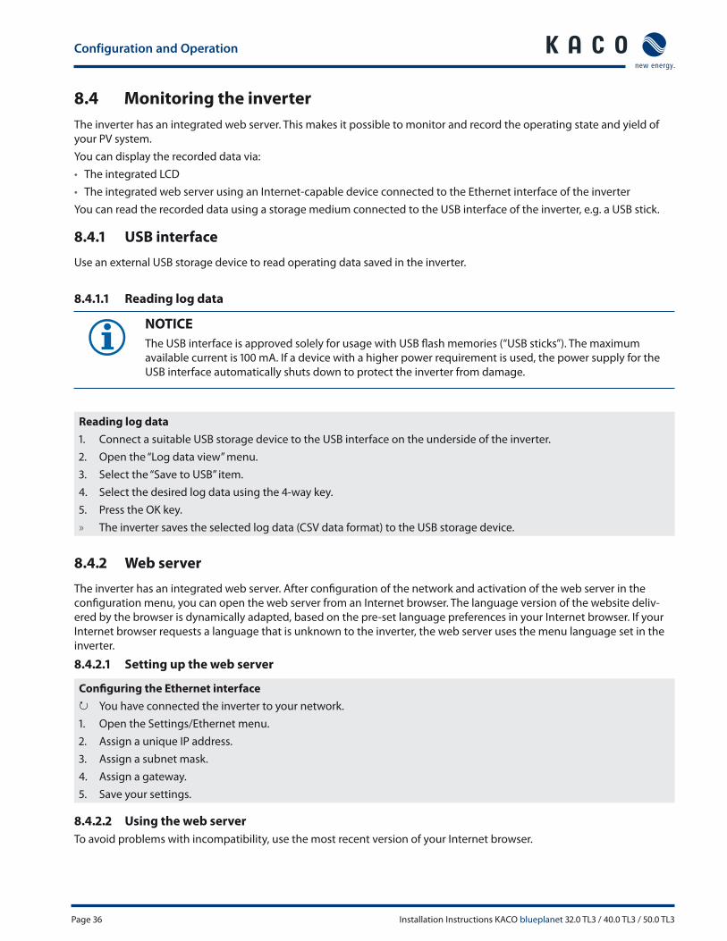
8.4.1 USB interface
Use an external USB storage device to read operating data saved in the inverter.
8.4.1.1 Reading log data
NOTICE
The USB interface is approved solely for usage with USB fl ash memories (“USB sticks”). The maximum
available current is 100 mA. If a device with a higher power requirement is used, the power supply for the
USB interface automatically shuts down to protect the inverter from damage.
Reading log data
1. Connect a suitable USB storage device to the USB interface on the underside of the inverter.
2. Open the “Log data view” menu.
3. Select the “Save to USB” item.
4. Select the desired log data using the 4-way key.
5. Press the OK key.
» The inverter saves the selected log data (CSV data format) to the USB storage device.
8.4.2 Web server
The inverter has an integrated web server. After confi guration of the network and activation of the web server in the
confi guration menu, you can open the web server from an Internet browser. The language version of the website deliv-
ered by the browser is dynamically adapted, based on the pre-set language preferences in your Internet browser. If your
Internet browser requests a language that is unknown to the inverter, the web server uses the menu language set in the
inverter.
8.4.2.1 Setting up the web server
Confi guring the Ethernet interface
↻ You have connected the inverter to your network.
1. Open the Settings/Ethernet menu.
2. Assign a unique IP address.
3. Assign a subnet mask.
4. Assign a gateway.
5. Save your settings.
8.4.2.2 Using the web server
To avoid problems with incompatibility, use the most recent version of your Internet browser.

Configuration and Operation
Installation Instructions KACO blueplanet 32.0 TL3 / 40.0 TL3 / 50.0 TL3 Page 37
NOTICE
You can also access the web server of the inverter via the Internet. To do this, additional settings of your
network confi guration, particularly your Internet router, are required.
Note that communication with the inverter is carried out over an unsecured connection, particularly in the
case of a connection over the Internet.
Calling up the web server
↻ Confi gure the Ethernet interface.
↻ Connect the Ethernet interface.
1. Open an Internet browser.
2. In the address fi eld of the Internet browser, enter the IP address of the inverter and call up the site.
» The Internet browser displays the start screen of the web server.
After it has been called up, the web server displays information about the inverter as well as the current yield data. The
web server supports the display of the following measurement data and yield data:
• Feed-in power • Generator power
• Status • Generator voltage
• Grid power • Unit temperature
• Grid voltage
In order to display and export yield data, proceed as follows:
Select the display period
1. Call up the web server.
2. Select the display period by choosing one of the keys: day view, month view, year view or overall view.
Filtering display data (day view only)
1. Call up the web server.
2. Select the day view.
3. To show or hide measured values, select or deselect the corresponding checkboxes in the “Select display” area.
Exporting data
1. Filter the display data if necessary.
2. Select the display period if applicable (day, month, year or overall view).
3. Click the “Export data” key.
4. Save the fi le.
NOTICE
Regardless of the display data selected in the “Select display” area, an export fi le always contains all
measurement data and yield data available for the selected period.

Configuration and Operation
Page 38 Installation Instructions KACO blueplanet 32.0 TL3 / 40.0 TL3 / 50.0 TL3
8.5 Performing a software update
You can update the software of the inverter to a new version using the integrated USB interface. Use a FAT32-formatted
USB stick to do this. Do not use any storage media with an external power supply (for example: an external hard disk).
NOTICE
Ensure that the power supply of the AC and DC sides is active. It is only possible to update all components
of the inverter to the most current software version in this operating state.
CAUTION
Damage to the inverter
The update can fail if the power supply is interrupted during the update process. Parts of the software or
of the inverter itself can then be damaged.
» Do not interrupt the DC and AC power supply during the update process.
Preparing for the software update
1. Download the software update fi le from the KACO web site and store it on your hard disk.
2. Extract the update fi le (.ZIP) completely onto the USB stick.
» Perform software update.
Performing the software update
↻ Prepare for the software update.
↻ Ensure the supply of DC and AC power.
3. Connect the USB stick to the inverter.
» The message “Confi guration found. Would you like to load it?” appears on the display.
4. If you would like to perform the update, select the "Yes" button.
» The inverter begins the update.
The update can take several minutes. The "Operating" LED fl ashes during the update process. The inverter may restart
several times. The update is fi nished when the desktop is shown on the display screen.
The inverter then returns to feed-in mode. You can check to see if the update was successful in the menu:
Displaying the software version
Open the Information / Software Version menu.
» The inverter will display the versions and checksums of the software that is currently loaded.
Maintenance/Troubleshooting
Installation Instructions KACO blueplanet 32.0 TL3 / 40.0 TL3 / 50.0 TL3 Page 39
9 Maintenance/Troubleshooting
9.1 Visual inspection
Inspect the inverter and the cables for visible damage and note the operating status display of the inverter. In case of
damage, notify your installer. Repairs may only be carried out by authorised electricians.
NOTE
The inverter should be checked for proper operation by a qualifi ed electrician at regular intervals.
9.2 External cleaning
DANGER
Lethal voltages in the inverter
Serious injuries or death can result if moisture enters the inverter.
› Only use completely dry objects to clean the inverter.
› Only the exterior of the inverter should be cleaned.
Cleaning the inverter
Do not use compressed air.
Use a vacuum cleaner or a soft brush to remove dust from the fan cover and from the top of the inverter on a regu-
lar basis.
Remove dust from the ventilation inlets if necessary.
Authorized electrician
9.3 Shutting down for maintenance and troubleshooting
DANGER
Lethal voltages are still present in the terminals and cables of the inverter even after the inverter has
been switched off and disconnected.
Severe injuries or death may occur if the cables and terminals in the inverter are touched.
Only appropriately qualifi ed and authorised electricians may open and maintain the inverter.
› Observe all safety regulations and the currently applicable technical connection specifi cations of the
responsible power supply company.
› Disconnect the AC and DC sides.
› Secure the AC and DC sides from being inadvertently switched back on.
› Do not open the inverter until after these two steps are complete.
› After shutdown, wait at least 30 minutes before working on the inverter.
CAUTION
Destruction of the DC connection
The connection terminals can be destroyed by arcing if disconnected while still live.
› It is absolutely necessary that the shutdown sequence be carried out in the correct order.

Maintenance/Troubleshooting
Page 40 Installation Instructions KACO blueplanet 32.0 TL3 / 40.0 TL3 / 50.0 TL3
Shutting down the inverter
5. Switch off the grid voltage by turning off the external circuit breakers.
6. Disconnect the PV generator using the DC isolator switch.
DANGER! The DC cables are still live.
Ensure that there is no voltage present on the grid connection terminals.
NOTE
The screw connections must be checked by installers at regular intervals to ensure they are tightened to
required torques (see page 7.3 on page 18).
9.4 Faults
9.4.1 Procedure
DANGER
Lethal voltages are still present in the terminals and cables of the inverter even after the inverter has
been switched off and disconnected.
Severe injuries or death may occur if the cables and terminals in the inverter are touched.
When a fault occurs, notify an appropriately authorised and qualifi ed electrician or KACO new energy
GmbH Service.
The operator can only carry out actions marked with a B.
In case of power failure, wait for the system to automatically restart.
Notify your electrician if there is an extended power failure.
9.4.2 Troubleshooting
B = Action of the operator
E = The indicated work may only be carried out by an authorised electrician.
K = The indicated work may only be carried out by a service employee of KACO new energy GmbH.
Fault Cause of fault Explanation/remedy By
The display is
blank and the
LEDs do not light
up.
Grid voltage not avail-
able
Check whether the DC and AC voltages are within the per-
mitted limits (see Technical Data).E
Notify KACO Service. E
The inverter stops
feeding into the
grid shortly after
being switched
on, even though
there is sunlight
present.
Faulty grid separation
relay in the inverter.
If the grid separation relay is defective, the inverter will recog-
nise this during the self-test.
Ensure that there is suffi cient PV generator power. E
If the grid separation relay is defective, have it replaced by
KACO Service.
Notify KACO Service.
E
Table 4: Troubleshooting

Maintenance/Troubleshooting
Installation Instructions KACO blueplanet 32.0 TL3 / 40.0 TL3 / 50.0 TL3 Page 41
Fault Cause of fault Explanation/remedy By
The inverter is
active but does
not feed into the
grid. The display
indicates a line
failure.
Grid-feed is interrupted
due to a grid fault.
Due to a grid fault (grid impedance too high, over/undervolt-
age, over/underfrequency), the inverter stopped the feed-in
process and disconnected from the grid for safety reasons.
Change the line parameters within the permitted operat-
ing limits (see the “Start-Up” section).E
The grid fuse
trips.
The grid fuse capacity is
too low.
In cases of high solar radiation, the inverter exceeds its rated
current for a short period, depending on the PV generator.
Select the capacity of the inverter’s pre-fuse to be some-
what higher than the maximum feed-in current (see the
“Installation” section).
E
Contact the grid operator if the grid failure continues to
occur.
E
Damage to the invert-
er’s hardware.
If the line fuse trips immediately when the inverter goes into
feed-in mode (after the start-up period is complete), the invert-
er’s hardware is probably damaged.
Contact KACO Service to test the hardware. E
The inverter dis-
plays an impos-
sible daily peak
value.
Faults in the grid. The inverter continues to operate as normal without losses to
the yield, even when an erroneous daily peak value is dis-
played. The value is reset overnight.
To reset the value immediately, switch the inverter off by
disconnecting it from the grid and switching off the DC,
then switch it back on.
E
Daily yields do
not correspond to
the yields on the
feed-in meter.
Tolerances of the meas-
uring elements in the
inverter.
The measuring elements of the inverter have been selected
to ensure maximum yields. Due to these tolerances, the daily
yields shown may deviate from the values on the feed-in meter
by up to 15%.
No action -
The inverter is
active but does
not feed into the
grid. Display:
“Waiting for feed-
in”
• Generator voltage too
low
• Grid voltage or PV
generator voltage
unstable.
• The PV generator voltage or power is not suffi cient for feed-
in (solar radiation is too low).
• The inverter checks the grid parameters before the feed-in
process begins. The length of time it takes to switch back on
again diff ers by country according to applicable standards
and regulations and can take several minutes.
• The starting voltage may have been set incorrectly.
Adjust starting voltage in the Parameter menu if required. K
Table 4: Troubleshooting

Maintenance/Troubleshooting
Page 42 Installation Instructions KACO blueplanet 32.0 TL3 / 40.0 TL3 / 50.0 TL3
Fault Cause of fault Explanation/remedy By
Noise emission
from the inverter.
Particular ambient con-
ditions.
When there are certain ambient conditions, the units may emit
audible noises.
• Grid interference or grid failure caused by particular loads
(motors, machines, etc.) which are either connected to
the same point on the grid or located in the vicinity of the
inverter.
• In cases of volatile weather conditions (frequent switching
between sunny and cloudy conditions) or strong solar radia-
tion, a light hum may be audible due to the increased power.
• Under certain grid conditions, resonances may form
between the unit’s input fi lter and the grid, which may be
audible even when the inverter is switched off .
These noise emissions do not aff ect the operation of the
inverter. They do not lead to loss of effi ciency, failure, damage
or to a shortening of the unit’s service life.
People with very sensitive hearing (particularly children) are
able to hear the high-frequency hum caused by the inverter’s
operating frequency of approximately 17 kHz.
No action
In spite of high
radiation levels,
the inverter does
not feed the
maximum power
into the grid.
The device is too hot
and the system limits
the power.
Because the temperatures inside the unit are too high, the
inverter reduces its power to prevent damage to the unit. Note
the technical data. Ensure that the convection cooling is not
impeded from the exterior. Do not cover the cooling fi ns.
Provide for suffi cient cooling of the unit.
Do not cover the cooling fi ns.
B, E
Table 4: Troubleshooting
9.5 "Fault" messages on the display/LED
Many fault signals indicate a fault in the grid. They are not operational faults of the inverter. The triggering levels are
defi ned in standards, e.g. VDE0126-1-1. The inverter shuts down if the values exceed or fall below the approved levels.
9.5.1 Display of status and fault messages
Display Fault LED (red)
FS (fault status) ON• Fault signal relay has switched.
• Feed-in was ended due to a fault.
OS (operating status) OFF
• The fault signal relay releases again.
• The inverter feeds back into the grid again after a coun-
try-specifi c time period.
Details regarding the fault or operating status can be found either on the display or in the data that was recorded through
the RS485 interface.

Maintenance/Troubleshooting
Installation Instructions KACO blueplanet 32.0 TL3 / 40.0 TL3 / 50.0 TL3 Page 43
9.5.2 Status and fault signals
The following table lists the possible status and fault signals that the inverter shows on the LCD and the LEDs.
BS = operating status, FS = fault status;
B = Action of the operator
E = The indicated work may only be carried out by an authorised electrician.
K = The indicated work may only be carried out by a service employee of KACO new energy GmbH.
Status Display Explanation Action
OS 1 Waiting for feed-in Self-test: The grid parameters and gen-
erator voltage are being checked.
- -
OS 2 Generator voltage
too low
Insuffi cient generator voltage and
power,
status before the transition to night
shutdown
- -
OS 8 Self-test Checks the shutdown of the power
electronics as well as the grid relay
before feed-in mode.
- -
FS 10 Temperature in
unit too high
In case of overheating (>140°F(60°C)),
the inverter switches off .
Possible causes:
• Ambient temperature too high,
• Fans covered,
• Inverter defective.
Cool off the area
around the inverter.
Uncover the fans.
Notify your author-
ised electrician.
B
B
E
OS 11 Power
limitation
If the generator power is too high, the inverter limits itself (e.g. around
noon if the generator capacity is too large) or the temperature of the heat
sink on the inverter is hotter than 75°C.
FS 18 Resid. current
shutdown
Residual current was detected. The
feed-in was interrupted.
Notify your author-
ised electrician.E
FS 19 Generator insulation
fault
There is an insulation fault on the PV
generator. The feed-in was interrupted.
Notify your author-
ised electrician if the
fault occurs several
times.
E
FS 30 Fault
Transformer fault
The current and voltage measure-
ments in the inverter are not within
acceptable range.
- -
FS 32 Fault
Self-test
The internal grid separation relay test
has failed.
Notify your author-
ised electrician if the
fault occurs several
times.
E
FS 33 Fault
DC feed-in
The DC feed-in has exceeded the per-
mitted value. This DC feed-in can be
caused by grid conditions and may not
neccessarily indicate a fault.
Notify your author-
ised electrician if the
fault occurs several
times.
E
Table 5: Operating status and fault messages on the display
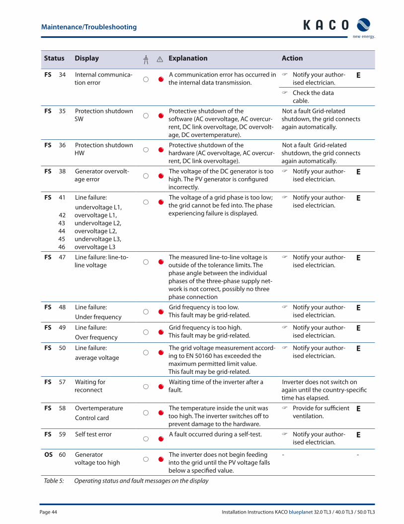
Maintenance/Troubleshooting
Page 44 Installation Instructions KACO blueplanet 32.0 TL3 / 40.0 TL3 / 50.0 TL3
Status Display Explanation Action
FS 34 Internal communica-
tion error
A communication error has occurred in
the internal data transmission.
Notify your author-
ised electrician.E
Check the data
cable.
FS 35 Protection shutdown
SW
Protective shutdown of the
software (AC overvoltage, AC overcur-
rent, DC link overvoltage, DC overvolt-
age, DC overtemperature).
Not a fault Grid-related
shutdown, the grid connects
again automatically.
FS 36 Protection shutdown
HW
Protective shutdown of the
hardware (AC overvoltage, AC overcur-
rent, DC link overvoltage).
Not a fault Grid-related
shutdown, the grid connects
again automatically.
FS 38 Generator overvolt-
age error
The voltage of the DC generator is too
high. The PV generator is confi gured
incorrectly.
Notify your author-
ised electrician.E
FS 41
42
43
44
45
46
Line failure:
undervoltage L1,
overvoltage L1,
undervoltage L2,
overvoltage L2,
undervoltage L3,
overvoltage L3
The voltage of a grid phase is too low;
the grid cannot be fed into. The phase
experiencing failure is displayed.
Notify your author-
ised electrician.E
FS 47 Line failure: line-to-
line voltage
The measured line-to-line voltage is
outside of the tolerance limits. The
phase angle between the individual
phases of the three-phase supply net-
work is not correct, possibly no three
phase connection
Notify your author-
ised electrician.E
FS 48 Line failure:
Under frequency
Grid frequency is too low.
This fault may be grid-related.
Notify your author-
ised electrician.E
FS 49 Line failure:
Over frequency
Grid frequency is too high.
This fault may be grid-related.
Notify your author-
ised electrician.E
FS 50 Line failure:
average voltage
The grid voltage measurement accord-
ing to EN 50160 has exceeded the
maximum permitted limit value.
This fault may be grid-related.
Notify your author-
ised electrician.E
FS 57 Waiting for
reconnect
Waiting time of the inverter after a
fault.
Inverter does not switch on
again until the country-specifi c
time has elapsed.
FS 58 Overtemperature
Control card
The temperature inside the unit was
too high. The inverter switches off to
prevent damage to the hardware.
Provide for suffi cient
ventilation.E
FS 59 Self test error A fault occurred during a self-test. Notify your author-
ised electrician.E
OS 60 Generator
voltage too high
The inverter does not begin feeding
into the grid until the PV voltage falls
below a specifi ed value.
- -
Table 5: Operating status and fault messages on the display

Maintenance/Troubleshooting
Installation Instructions KACO blueplanet 32.0 TL3 / 40.0 TL3 / 50.0 TL3 Page 45
Status Display Explanation Action
OS 61 External
limit (%)
The external limit Power control was activated by the grid operator. The
inverter limits its power. (SCADA)
OS 63 Measured values P(f )/frequency-dependent power reduction: Frequency-dependent
power reduction will be activated when the BDEW (German Association of
Energy and Water Industries) Medium Voltage Directive goes into eff ect.
Power reduction starts at a frequency of 50.2 Hz.
OS 64 Measured values Output current limiting: The AC current is limited once the specifi ed maxi-
mum value has been reached.
FS 67 Fault
at power section 1
There is a fault in the power section. Notify your author-
ised electrician.E
FS 70 Fan error The fan is malfunctioning. Replace
defective fanE
FS 73 Standalone grid err. Standalone mode was detected. - -
OS 74 External idle power
requirement
The grid operator limits the feed-in
power of the inverter.
- -
FS 78 Resid. current shut-
down
Measured AFI fault current was > 180
mA. Fault results in immediate shut-
down of the device.
Notify authorised
electrician / KACO
Service
E/K
OS 79 Insulation measure-
ment
PV generator’s insulation is being
measured
- -
FS 80 Insulation meas. not
possible
The insulation measurement cannot
be performed because the generator
voltage is too volatile.
- -
FS 81,
82,
83
Protection shutdown
line volt.
L1 L2, L3
Overvoltage has been detected on
a conductor. An internal protective
mechanism has disconnected the
device to protect it against damage.
In case of repeated
occurrence:
Notify your author-
ised electrician.
E
FS 84 Protection shutdown
undervolt. DC link
A voltage deviation has been found
in the DC link. An internal protective
mechanism has disconnected the
device to protect it against damage.
In case of repeated
occurrence:
Notify your author-
ised electrician.
E
FS 85 Protection shutdown
overvolt. DC linkE
FS 86 Protect. shutdown
DC link asymmetry
Overvoltage has been found in the DC
link. An internal protective mechanism
has disconnected the device to protect
it against damage.
In case of repeated
occurrence:
Notify your author-
ised electrician.
E
FS 87,
88,
89
Protection shutdown
overcurrent L1, L2, L3
A current that has been found on a
conductor is too high. An internal
protective mechanism has discon-
nected the device to protect it against
damage.
In case of repeated
occurrence:
Notify your author-
ised electrician.
E
FS 93,
94
Self test error Buff er
1, Buff er 2
The control board is defective. Notify authorised
electrician / KACO
Service
E/K
Table 5: Operating status and fault messages on the display
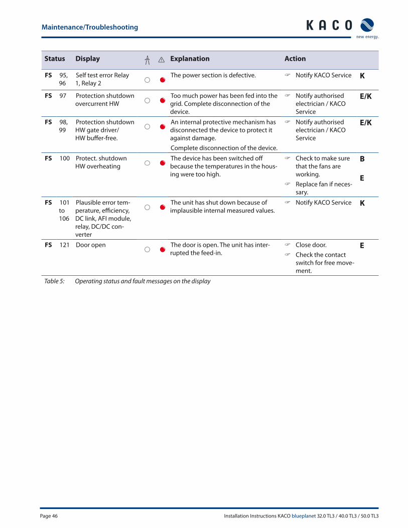
Maintenance/Troubleshooting
Page 46 Installation Instructions KACO blueplanet 32.0 TL3 / 40.0 TL3 / 50.0 TL3
Status Display Explanation Action
FS 95,
96
Self test error Relay
1, Relay 2
The power section is defective. Notify KACO Service K
FS 97 Protection shutdown
overcurrent HW
Too much power has been fed into the
grid. Complete disconnection of the
device.
Notify authorised
electrician / KACO
Service
E/K
FS 98,
99
Protection shutdown
HW gate driver/
HW buff er-free.
An internal protective mechanism has
disconnected the device to protect it
against damage.
Complete disconnection of the device.
Notify authorised
electrician / KACO
Service
E/K
FS 100 Protect. shutdown
HW overheating
The device has been switched off
because the temperatures in the hous-
ing were too high.
Check to make sure
that the fans are
working.
Replace fan if neces-
sary.
B
E
FS 101
to
106
Plausible error tem-
perature, effi ciency,
DC link, AFI module,
relay, DC/DC con-
verter
The unit has shut down because of
implausible internal measured values.
Notify KACO Service K
FS 121 Door open The door is open. The unit has inter-
rupted the feed-in.
Close door.
Check the contact
switch for free move-
ment.
E
Table 5: Operating status and fault messages on the display

Service
Installation Instructions KACO blueplanet 32.0 TL3 / 40.0 TL3 / 50.0 TL3 Page 47
10 Service
If you need help solving a technical problem with one of our KACO products, please contact our service hotline.
Please have the following information ready so that we can help you quickly and effi ciently:
• Inverter type / serial number
• Fault message shown on the display / Description of the fault / Did you notice anything unusual? / What has already
been done to analyse the fault?
• Module type and string circuit
• Date of installation / Start-up report
• Consignment identifi cation / Delivery address / Contact person (with telephone number)
• Information about the accessibility of the installation site.
Any additional costs arising from unfavourable structural or mounting conditions shall be billed to the customer.
You can fi nd our warranty conditions on our website:
http://www.kaco-newenergy.com/service/warranty
From there, you can easily navigate to our international websites by clicking on the appropriate fl ag(s).
Please use our website to register your unit immediately:
http://www.kaco-newenergy.com/service/warranty/online-warranty-registration
In this manner, you can assist us in providing you with the quickest service possible.
Note: The maximum length of the warranty is based on the currently applicable national warranty conditions.
We have prepared a template for complaints. It is located at
http://www.kaco-newenergy.de/en/site/service/kundendienst/index.xml.
Hotlines
Technical troubleshooting +1 866 KACOSOL (1 (866) 522-6765)
Technical consultation +1 866 KACOSOL (1 (866) 522-6765)
(*) Also on Saturdays from 8:00 a.m. to 2:00 p.m. (CET)
11 Shutdown/Disassembly
11.1 Shutting down the inverter
DANGER
Lethal voltages are still present in the terminals and cables of the inverter even after the inverter has
been switched off and disconnected.
Severe injuries or death may occur if the cables and terminals in the inverter are touched.
› After shutdown, wait at least 5 minutes before working on the inverter.
Recycling and disposal
Page 48 Installation Instructions KACO blueplanet 32.0 TL3 / 40.0 TL3 / 50.0 TL3
DANGER
Destruction of the DC plug
DC plugs can be destroyed by arcing if disconnected while still live.
› It is absolutely necessary that the shutdown sequence be carried out in the correct order.
Shutdown sequence
1. Disconnect the mains voltage using the AC isolator switch.
2. Disconnect the photovoltaic generator using the DC isolator switches.
DANGER! The DC cables are still live.
Ensure that there is no voltage present on the grid connection terminals.
11.2 Uninstalling the inverter
↻ Shut down the inverter.
1. Unlock and open the housing door.
2. Open the connection cover connection area.
3. Remove the interface cable.
4. Release the DC and AC cables from the connection terminals.
5. Pull out the cables.
» The uninstallation of the inverter is complete. Continue with dismantling.
11.3 Dismantling the inverter
↻ Shut down the inverter.
↻ Uninstall the inverter.
1. Remove the inverter fastening.
2. Securely pack up the inverter if it is to be used later
or
have the inverter disposed of professionally.
12 Recycling and disposal
For the most part, both the inverter and the corresponding transport packaging are made from recyclable materials.
KACO does its best to ensure our vendors follow a low carbon manufacturing process as we do ourselves. It is not always
possible but if you have questions about our products or the components in our products don’t hesitate to call +1 866
KACOSOL and ask.
Device
Do not dispose of faulty inverters or accessories together with household waste. Ensure that the old unit and, where
applicable, any accessories are disposed of in a proper manner. Most areas have public electronic waste disposal and/or
recycling plants. Feel free to contact KACO at +1 866 KACOSOL to request information about e-waste recycling in your
area.
Packaging
Ensure that the transport packaging is recycled.
Appendix
Installation Instructions KACO blueplanet 32.0 TL3 / 40.0 TL3 / 50.0 TL3 Page 49
13 Appendix
EU Declaration of Conformity
Vendor’s name
and address
KACO new energy GmbH
Carl-Zeiss-Straße 1
74172 Neckarsulm, Germany
Product description Photovoltaic feed-in inverter
Type designation KACO blueplanet 32.0 TL3 – M1/M3
KACO blueplanet 40.0 TL3 – M1/M3
KACO blueplanet 50.0 TL3 – M1/M3
This is to confi rm that the units listed above comply with the protection requirements set forth in the Directive of the
Council of the European Union of 15th December 2004 on the harmonisation of the laws of the member states relating to
electromagnetic compatibility (2004/108/EC) and the Low Voltage Directive (2006/95/EC).
The units conform to the following standards:
2006/95/EC
“Directive relating to electrical
equipment designed for use
within specifi c voltage limits”
Safety of the unit
IEC 62109-1:2010
IEC 62109-2:2011
Interference immunity
EN 61000-6-1:2007
2004/108/EC
“Directive relating to electromagnetic
compatibility”
Emitted interference
EN 61000-6-3:2007
Secondary eff ects on the grid
EN 61000-3-12:2005
EN 61000-3-11:2000
The types mentioned above are therefore labelled with the CE mark.
Unauthorized modifi cations to the supplied units and/or any use of the units that is contrary to their proper use shall
render this Declaration of Conformity null and void.
Neckarsulm, 11/04/2013
KACO new energy GmbH
p.p. Matthias Haag
CTO

Appendix
Page 50 Installation Instructions KACO blueplanet 32.0 TL3 / 40.0 TL3 / 50.0 TL3


KACO new energy (866) 522 6765 [email protected] www.kaco-newenergy.com
Th
e t
ext
an
d fi
gu
res
refl
ect
th
e c
urr
en
t te
chn
ica
l sta
te a
t th
e t
ime
of
pri
nti
ng
. S
ub
ject
to
te
chn
ica
l ch
an
ge
s. E
rro
rs a
nd
om
issi
on
s e
xce
pte
d.
30
05
15
1-0
1-1
30
41
1


![SS90 - Trinity Highway · SS90 HD TMA is certified for various speed levels as shown in TL3.UK: 110 km/h [68 mph]. TL3.UK: 110 km/h [68 mph] Highways Agency directed tests are not](https://img.pdfslide.us/doc/110x75/60e512d5bc3f7548900d7759/ss90-trinity-highway-ss90-hd-tma-is-certified-for-various-speed-levels-as-shown.jpg)