Embed Size (px)
Citation preview

INSTRUCTION MANUALCOMPUTERIZED LENSMETER
CL-200

INTRODUCTION
Thank you for purchasing the TOPCON Computerized Lensmeter CL-200.
This instrument has the following features:• High accuracy measurements with ease of operation• Easy to use color LCD
This Instruction Manual covers an overview of the TOPCON Computerized Lensmeter CL-200, basic operations, troubleshooting, maintenance and cleaning.To ensure the efficient, safe use, read through “Safety Indications” and “Safety Precau-tions” and use the instrument correctly.Keep this Instruction Manual within reach for future reference.
This symbol is applicable for EU member countries only.To avoid potential negative consequences for the environment and possibly human health, this instrument should be disposed of (i) for EU member countries - in accordance with WEEE (Directive on Waste Electrical and Electronic Equipment), or (ii) for all other countries, in accordance with local disposal and recycling laws.
1
WORKING ENVIRONMENT
Indoor use Altitude up to 2,000mPollution degree II Temperature range: 5-40°CMaximum relative humidity 80% for temperatures up to 31°C decreasing linearly to 50% rela-tive humidity at 40°C
STORAGE METHOD (without package)
1. ENVIRONMENTAL CONDITIONSIndoor use Altitude up to 2,000mPollution degree II Temperature range: 5~40°CMaximum relative humidity 80% for temperatures up to 31°C decreasing linearly 50% relativehumidity at 40°C
2. IF THE INSTRUMENT IS PLACED IN STORAGE, KEEP IT(1) Free from water splashes(2) Free from adverse effects due to atmospheric pressure, temperature, moisture, ventila-
tion, sunlight, dust, salt, content, sulfur, etc.(3) Stable and free from vibration shock (including transportation) and insure that it is always
stored in an upright position.(4) Free from chemicals and gases.
TRANSPORT AND STORAGE CONDITIONS (with package)
Temperature: -20°C-50°CHumidity: 10-95%
MAINTENANCE AND CHECKS1. Regularly maintain and check all equipment and parts.2. When the instrument is not in use, protect the instrument by covering it with the dust cover.
2

DISPLAYS FOR SAFE USEIn order to encourage the safe use of this product, warnings labels are placed on the product andwritten in the instruction manual.We suggest that everyone understands the meaning of the following displays and icons beforereading the “Safety Cautions” and text.
DISPLAY MEANING
Improper handling or ignoring this display may lead tothe possibility of death or serious injury.
Improper handling or ignoring this display may causepersonal injury or physical damage.
• Injury refers to cuts, bruises, burns, electric shock, etc.• Physical damage refers to extensive damage that may involve the building, peripheral
equipment and furniture.
ICONS MEANING
This icon indicates an action to be avoided.Specific contents are shown with words or an illustrationclose to the icon.
This icon indicates a Mandatory Action.Specific contents are shown with words or an illustrationclose to the icon.
This icon indicates a Hazard Alerting (Warning).Specific contents are shown with text or an illustrationclose to the icon.
WARNING
CAUTION
3
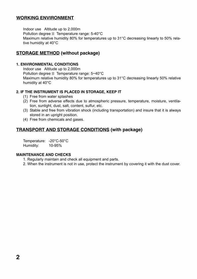
SAFETY PRECAUTIONS
Icons Prevention item Page
To avoid fire/electric shocks, connect the power plug to a 3P ACoutlet (with ground) and secure grounding. 15
To prevent electrical shock, turn off the power switch and discon-nect power cable before replacing fuses. Replace fuses with the same rating and type.
33
To avoid electric shocks, do not attempt disassembling, rebuildingor repairing. For repairs, call your dealer. —
To avoid fire/electric shocks, do not install the instrument in a placewhere it may get wet. —
If there is a malfunction or if the instrument produces smoke, imme-diately turn OFF the POWER switch and unplug the power cable.To a avoid a possible fire due to malfunction, call your dealer andask for repairs.
—
Icons Prevention item Page
To avoid injury by falling, do not install the instrument on a slope orin an unstable place. 15
To avoid electric shocks, do not handle the power plug with wethands. —
This instrument has been tested (with 100-240V) and found to com-ply with IEC60601-1-2: 2001.This instrument radiates radio frequency energy within standardand may affect other devices in vicinity.If you have found out by turning on/off the instrument that it affectsother devices, it is recommended to change the direction, keep aproper distance against other devices or change the outlet.If you have a question, consult with the selling agent.
—
WARNING
CAUTION
4
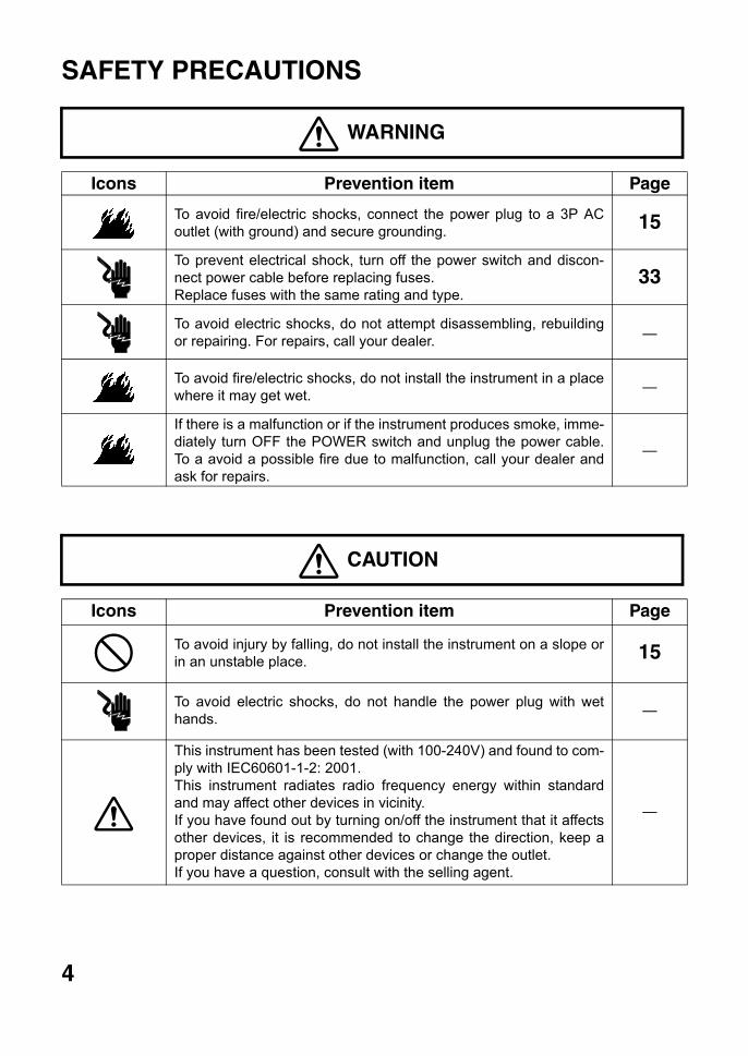
USAGE AND MAINTENANCE
USER MAINTENANCE
To maintain the safety and performance of the equipment, never attempt to repair or performmaintenance. These tasks should be performed by an authorized service representative.Maintenance tasks that can be performed by the user are as follows; for details, follow themanual’s instructions.
OPERATING THE FUSE:The fuse is replaceable.For details, see page 33 of this manual.
CLEANING COVER GLASSESFor details, see page 34 of this manual.
ESCAPE CLAUSE
Usage:This lensmeter is an electric instrument and it must be used in accordance with its Instruction Manual.
• TOPCON shall not take any responsibility for damages due to fire, groundquake, actions bythird person, or the negligence and misuse by the user and used under unusual conditions.
• TOPCON shall not take any responsibility for damage derived from the inability to use thisequipment, such as a loss of business profit and suspension of business.
• TOPCON shall not take any responsibility for damage caused by operations other thanthose described in this Instruction Manual.
5
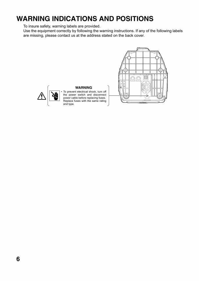
WARNING INDICATIONS AND POSITIONSTo insure safety, warning labels are provided.Use the equipment correctly by following the warning instructions. If any of the following labelsare missing, please contact us at the address stated on the back cover.
WARNING• To prevent electrical shock, turn off
the power switch and disconnectpower cable before replacing fuses.Replace fuses with the same ratingand type.
6
7
CONTENTINTRODUCTION ........................................................................................................1DISPLAYS FOR SAFE USE.......................................................................................3SAFETY PRECAUTIONS...........................................................................................4USAGE AND MAINTENANCE....................................................................................5USER MAINTENANCE...............................................................................................5ESCAPE CLAUSE......................................................................................................5WARNING INDICATIONS AND POSITIONS .............................................................6
COMPONENTSCOMPONENT NAMES...............................................................................................8ACCESSORIES..........................................................................................................9
MONITORMONITOR SCREEN.................................................................................................10MENU SCREEN .......................................................................................................12MENU LIST...............................................................................................................13
PREPARATIONINSTALLATION ........................................................................................................15SETTING THE PAPER.............................................................................................15
USING THE INSTRUMENTMEASURING ............................................................................................................17AXIS MARKING (CARTRIDGE SPECIFICATION/STEEL NEEDLE SPECIFICATION) .....................26PRINTING ADDITIONAL TEXTBOX (WITH PRINTER SPECIFICATION) ..............28SETTING A SEQUENCE NO. ..................................................................................29ABBE COMPENSATION FUNCTION.......................................................................30LENS PROTECTION PAD .......................................................................................30COMPARTMENT SPACE.........................................................................................30MEASURING PD (PD FITTING)(WITH PD SPECIFICATION).................................31
MAINTENANCE ........................................................................................................33
BEFORE REQUESTING SERVICECAUTION MESSAGES ............................................................................................35CHECK ITEMS .........................................................................................................35
SPECIFICATIONSSPECIFICATIONS....................................................................................................36WITH PRINTER SPECIFICATION ...........................................................................36ELECTROMAGNETIC COMPATIBILITY..................................................................37SYSTEM CLASSIFICATION ....................................................................................41OPTIONAL ACCESSORIES.....................................................................................41SHAPE OF PLUG.....................................................................................................42SYMBOL...................................................................................................................42
USING THE INSTRUMENT AS A SYSTEMON - LINE SYSTEM .................................................................................................43USB ..........................................................................................................................43
COMPONENTS
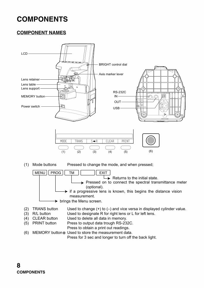
COMPONENT NAMES
(1) Mode buttons Pressed to change the mode, and when pressed;
(2) TRANS button Used to change (+) to (–) and vice versa in displayed cylinder value.(3) R/L button Used to designate R for right lens or L for left lens.(4) CLEAR button Used to delete all data in memory.(5) PRINT button Press to output data trough RS-232C.
Press to obtain a print out readings.(6) MEMORY button Used to store the measurement data.
Press for 3 sec and longer to turn off the back light.
Axis marker lever
BRIGHT control dial
LCD
Lens retainerLens tableLens support
MEMORY button
Power switch
IN
OUT
RS-232C
USB
(6)
PROG TMMENU EXIT
Returns to the initial state.Pressed on to connect the spectral transmittance meter(optional).
if a progressive lens is known, this begins the distance visionmeasurement.
brings the Menu screen.
8COMPONENTS
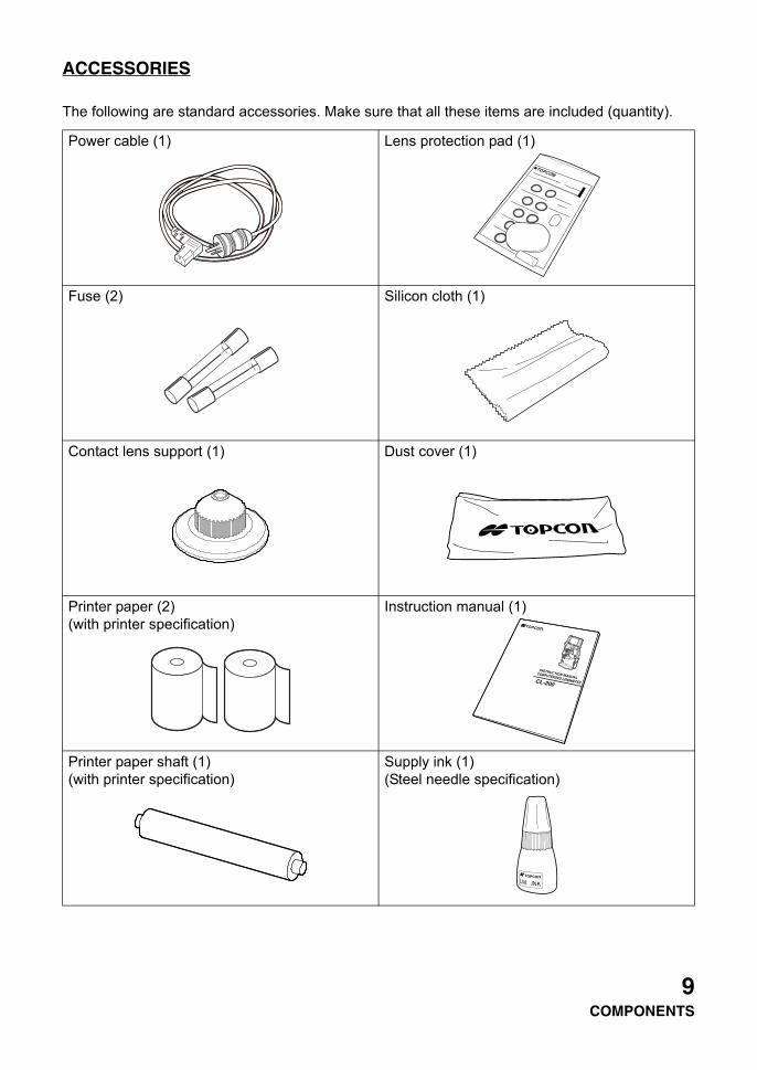
ACCESSORIES
The following are standard accessories. Make sure that all these items are included (quantity).
Power cable (1) Lens protection pad (1)
Fuse (2) Silicon cloth (1)
Contact lens support (1) Dust cover (1)
Printer paper (2)(with printer specification)
Instruction manual (1)
Printer paper shaft (1)(with printer specification)
Supply ink (1)(Steel needle specification)
COMPUTERIZED LENSMETER
9COMPONENTS
MONITOR
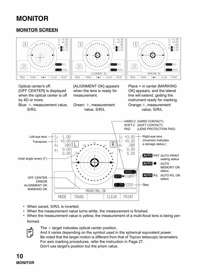
MONITOR SCREEN
• When saved, S/R/L is inverted.• When the measurement value turns white, the measurement is finished.• When the measurement value is yellow, the measurement of a multi-focal lens is being per-
formed.
Optical center's off.[OFF CENTER] is displayed when the optical center is off by 4D or more.Blue: , measurement value,
S/R/L
[ALIGNMENT OK] appears when the lens is ready for measurement.
Green: , measurement value, S/R/L
Place + in center [MARKING OK] appears, and the lateral line will extend, getting the instrument ready for marking.Orange: , measurement
value, S/R/L
The target indicates optical center position.And it varies depending on the symbol used in the spherical equivalent power.Be noted that the target motion is different from that of Topcon telescopic lensmeters.For axis marking procedures, refer the instruction in Page 27.Don't use target's position but the prism value.
Left-eye lensTranspose
Axial angle (every 5°)
OFF CENTERERROR
ALIGNMENT OKMARKING OK
HARD.C (HARD CONTACT)SOFT.C (SOFT CONTACT)PAD (LENS PROTECTION PAD)
Right-eye lens(Inversion indicates a storage status.)
PRT:AUTO PRINT waiting status
:AUTO MEMORY ON status
R/L :AUTO R/L ONstatus
AUTO
AUTO
AUTO
Step
10MONITOR
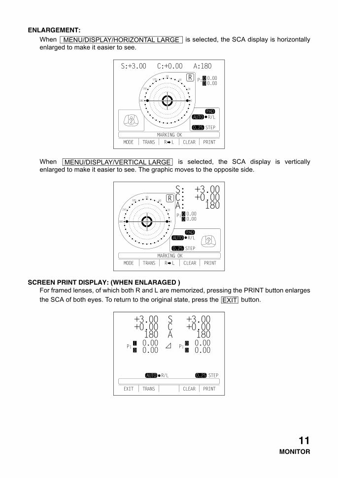
ENLARGEMENT:When is selected, the SCA display is horizontallyenlarged to make it easier to see.
When is selected, the SCA display is verticallyenlarged to make it easier to see. The graphic moves to the opposite side.
SCREEN PRINT DISPLAY: (WHEN ENLARAGED )For framed lenses, of which both R and L are memorized, pressing the PRINT button enlargesthe SCA of both eyes. To return to the original state, press the button.
MENU/DISPLAY/HORIZONTAL LARGE
MENU/DISPLAY/VERTICAL LARGE
EXIT
11MONITOR
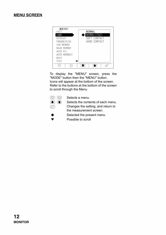
MENU SCREEN
To display the "MENU" screen, press the"MODE" button then the "MENU" button.Icons will appear at the bottom of the screen.Refer to the buttons at the bottom of the screento scroll through the Menu.
Selects a menu.Selects the contents of each menu.Changes the setting, and return to the measurement screen.Selected the present menuPossible to scroll
12MONITOR
MENU LIST
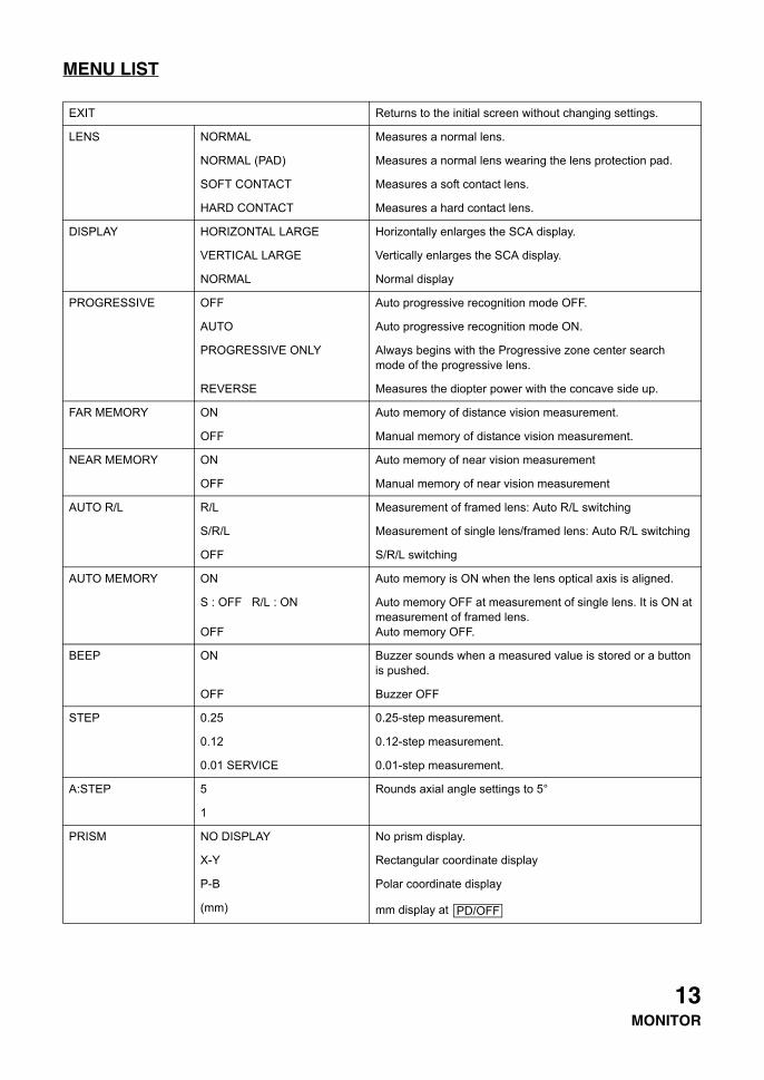
EXIT Returns to the initial screen without changing settings.
LENS NORMAL Measures a normal lens.
NORMAL (PAD) Measures a normal lens wearing the lens protection pad.
SOFT CONTACT Measures a soft contact lens.
HARD CONTACT Measures a hard contact lens.
DISPLAY HORIZONTAL LARGE Horizontally enlarges the SCA display.
VERTICAL LARGE Vertically enlarges the SCA display.
NORMAL Normal display
PROGRESSIVE OFF Auto progressive recognition mode OFF.
AUTO Auto progressive recognition mode ON.
PROGRESSIVE ONLY Always begins with the Progressive zone center search mode of the progressive lens.
REVERSE Measures the diopter power with the concave side up.
FAR MEMORY ON Auto memory of distance vision measurement.
OFF Manual memory of distance vision measurement.
NEAR MEMORY ON Auto memory of near vision measurement
OFF Manual memory of near vision measurement
AUTO R/L R/L Measurement of framed lens: Auto R/L switching
S/R/L Measurement of single lens/framed lens: Auto R/L switching
OFF S/R/L switching
AUTO MEMORY ON Auto memory is ON when the lens optical axis is aligned.
S : OFF R/L : ON
OFF
Auto memory OFF at measurement of single lens. It is ON at measurement of framed lens.Auto memory OFF.
BEEP ON Buzzer sounds when a measured value is stored or a button is pushed.
OFF Buzzer OFF
STEP 0.25 0.25-step measurement.
0.12 0.12-step measurement.
0.01 SERVICE 0.01-step measurement.
A:STEP 5 Rounds axial angle settings to 5°
1
PRISM NO DISPLAY No prism display.
X-Y Rectangular coordinate display
P-B Polar coordinate display
(mm) mm display at PD/OFF
13MONITOR
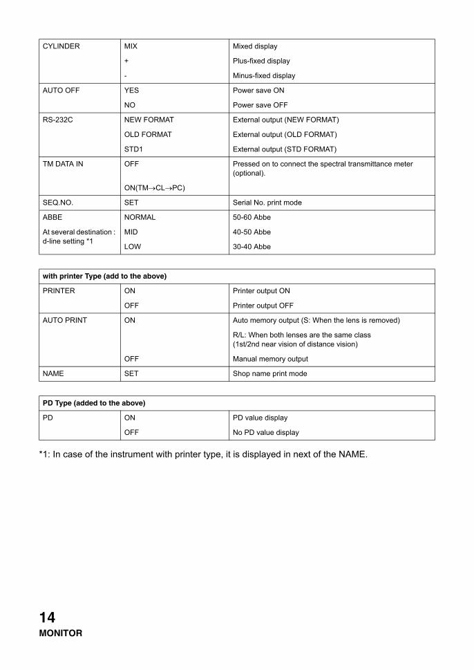
*1: In case of the instrument with printer type, it is displayed in next of the NAME.
CYLINDER MIX Mixed display
+ Plus-fixed display
- Minus-fixed display
AUTO OFF YES Power save ON
NO Power save OFF
RS-232C NEW FORMAT External output (NEW FORMAT)
OLD FORMAT External output (OLD FORMAT)
STD1 External output (STD FORMAT)
TM DATA IN OFF Pressed on to connect the spectral transmittance meter (optional).
ON(TM→CL→PC)
SEQ.NO. SET Serial No. print mode
ABBE NORMAL 50-60 Abbe
At several destination : d-line setting *1
MID 40-50 Abbe
LOW 30-40 Abbe
with printer Type (add to the above)
PRINTER ON Printer output ON
OFF Printer output OFF
AUTO PRINT ON Auto memory output (S: When the lens is removed)
R/L: When both lenses are the same class (1st/2nd near vision of distance vision)
OFF Manual memory output
NAME SET Shop name print mode
PD Type (added to the above)
PD ON PD value display
OFF No PD value display
14MONITOR
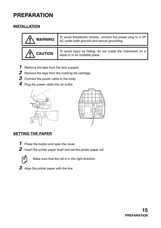
PREPARATION
INSTALLATION
1 Remove the tape from the lens support.
2 Remove the tape from the marking ink cartridge.
3 Connect the power cable to the body.
4 Plug the power cable into an outlet.
SETTING THE PAPER
1 Press the button and open the cover.
2 Insert the printer paper shaft and set the printer paper roll.
3 Align the printer paper with the line.
WARNINGTo avoid fire/electric shocks, connect the power plug to a 3PAC outlet (with ground) and secure grounding.
CAUTIONTo avoid injury by falling, do not install the instrument on aslope or in an unstable place.
Make sure that the roll is in the right direction.
15PREPARATION

4 Close the cover.
• Printer feed function : Press print button while pressing clear button.
• Do not install the instrument in a place which is exposed to direct sunlight, hightemperature, humidity or dust.
• Do not install the instrument at a place exposed to intense light or on a glossytable.
• The instrument may not operate properly or "ERROR" may be displayed.• Working enviroment
Indoor use Altitude up to 2,000mPollution degree II Temperature range: 5-40°CMaximum relative humidity 80% for temperatures up to 31°C decreasing linearlyto 50% relative humidity at 40°C
• Use a power of AC100-240V/±10% (50/60Hz)• Use transient overvoltages typically present on the power.• Do not install the equipment so that it is difficult to operate Power switch.
Button
Cover
Shaft
Align paper with this line.
16PREPARATION
USING THE INSTRUMENT
MEASURING
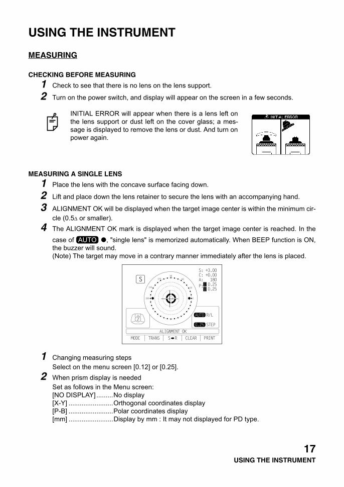
CHECKING BEFORE MEASURING
1 Check to see that there is no lens on the lens support.
2 Turn on the power switch, and display will appear on the screen in a few seconds.
MEASURING A SINGLE LENS
1 Place the lens with the concave surface facing down.
2 Lift and place down the lens retainer to secure the lens with an accompanying hand.
3 ALIGNMENT OK will be displayed when the target image center is within the minimum cir-cle (0.5∆ or smaller).
4 The ALIGNMENT OK mark is displayed when the target image center is reached. In the
case of , "single lens" is memorized automatically. When BEEP function is ON,the buzzer will sound.(Note) The target may move in a contrary manner immediately after the lens is placed.
1 Changing measuring stepsSelect on the menu screen [0.12] or [0.25].
2 When prism display is neededSet as follows in the Menu screen:[NO DISPLAY] .........No display [X-Y] ........................Orthogonal coordinates display[P-B] ........................Polar coordinates display[mm] ........................Display by mm : It may not displayed for PD type.
INITIAL ERROR will appear when there is a lens left onthe lens support or dust left on the cover glass; a mes-sage is displayed to remove the lens or dust. And turn onpower again.
AUTO
17USING THE INSTRUMENT
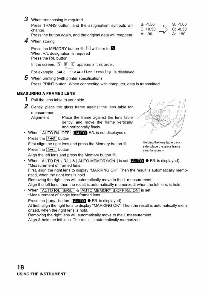
3 When transposing is requiredPress TRANS button, and the astigmatism symbols willchange.Press the button again, and the original data will reappear.
4 When storing
Press the MEMORY button . will turn to .When R/L designation is requiredPress the R/L button.In the screen, appears in this order.
For example, is displayed.5 When printing (with printer specification)
Press PRINT button. When connecting with computer, data is transmitted.
MEASURING A FRAMED LENS
1 Pull the lens table to your side.
2 Gently, place the glass frame against the lens table formeasurement.Alignment Place the frame against the lens table
gently, and move the frame verticallyand horizontally finely.
• When ( R/L is not displayed):Press the button.First align the right lens and press the Memory button .Press the button.Align the left lens and press the Memory button .
• When & is set ( R/L is displayed):*Measurement of framed lens.First, align the right lens to display “MARKING OK”. Then the result is automatically memo-rized, when the right lens is hold.Removing the right lens will automatically move to the L measurement.Align the left lens, then the result is automatically memorized, when the left lens is hold.
• When & is set:*Measurement of single lens/framed lensPress the button. ( R/L is displayed)At first, align the right lens to display "MARKING OK". Then the result is automatically mem-orized, when the right lens is hold.Removing the right lens will automatically move to the L measurement.Align & hold the left lens. The result is automatically memorized.
S: -1.50 S: -1.00C: +0.50 C: -0.50A: 90 A: 180
Holding the lens table back side, place the glass frame simultaneously.
AUTO R/L OFF AUTO
AUTO R/L / R/L AUTO MEMORY/ON AUTO
AUTO R/L S/R/L AUTO MEMORY S:OFF R/L:ON
AUTO
18USING THE INSTRUMENT
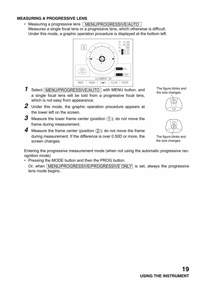
MEASURING A PROGRESSIVE LENS• Measuring a progressive lens
Measures a single focal lens or a progressive lens, which otherwise is difficult.Under this mode, a graphic operation procedure is displayed at the bottom left.
1 Select with MENU button, anda single focal lens will be told from a progressive focal lens,which is not easy from appearance.
2 Under this mode, the graphic operation procedure appears atthe lower left on the screen.
3 Measure the lower frame center (position ); do not move theframe during measurement.
4 Measure the frame center (position ); do not move the frameduring measurement. If the difference is over 0.50D or more, thescreen changes.
Entering the progressive measurement mode (when not using the automatic progressive rec-ognition mode)• Pressing the MODE button and then the PROG button.
Or, when is set, always the progressivelens mode begins.
MENU/PROGRESSIVE/AUTO
The figure blinks and the size changes.
The figure blinks and the size changes.
MENU/PROGRESSIVE/AUTO
1
2
MENU/PROGRESSIVE/PROGRESSIVE ONLY
19USING THE INSTRUMENT
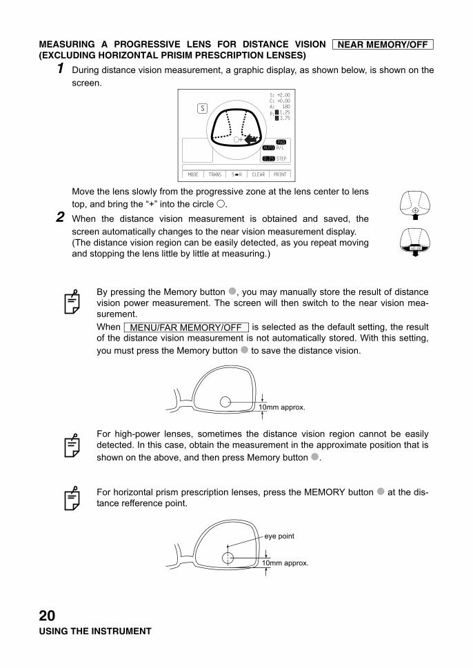
MEASURING A PROGRESSIVE LENS FOR DISTANCE VISION (EXCLUDING HORIZONTAL PRISIM PRESCRIPTION LENSES)
1 During distance vision measurement, a graphic display, as shown below, is shown on thescreen.
Move the lens slowly from the progressive zone at the lens center to lenstop, and bring the “+” into the circle .
2 When the distance vision measurement is obtained and saved, thescreen automatically changes to the near vision measurement display.(The distance vision region can be easily detected, as you repeat movingand stopping the lens little by little at measuring.)
By pressing the Memory button , you may manually store the result of distancevision power measurement. The screen will then switch to the near vision mea-surement.When is selected as the default setting, the resultof the distance vision measurement is not automatically stored. With this setting,you must press the Memory button to save the distance vision.
For high-power lenses, sometimes the distance vision region cannot be easilydetected. In this case, obtain the measurement in the approximate position that isshown on the above, and then press Memory button .
For horizontal prism prescription lenses, press the MEMORY button at the dis-tance refference point.
NEAR MEMORY/OFF
MENU/FAR MEMORY/OFF
10mm approx.
10mm approx.
eye point
20USING THE INSTRUMENT
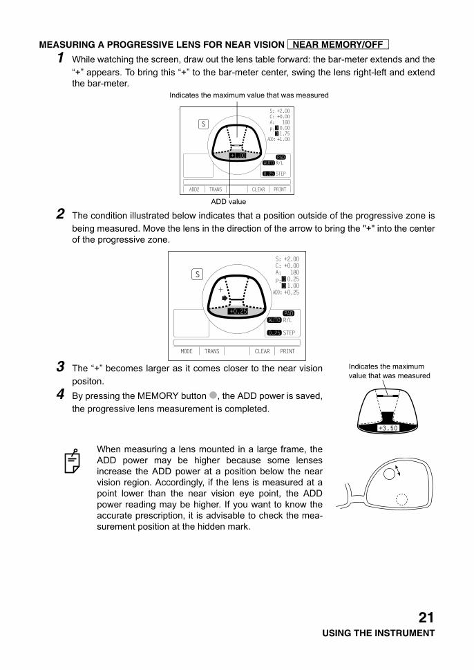
MEASURING A PROGRESSIVE LENS FOR NEAR VISION
1 While watching the screen, draw out the lens table forward: the bar-meter extends and the“+” appears. To bring this “+” to the bar-meter center, swing the lens right-left and extendthe bar-meter.
2 The condition illustrated below indicates that a position outside of the progressive zone isbeing measured. Move the lens in the direction of the arrow to bring the "+" into the centerof the progressive zone.
3 The “+” becomes larger as it comes closer to the near visionpositon.
4 By pressing the MEMORY button , the ADD power is saved,the progressive lens measurement is completed.
When measuring a lens mounted in a large frame, theADD power may be higher because some lensesincrease the ADD power at a position below the nearvision region. Accordingly, if the lens is measured at apoint lower than the near vision eye point, the ADDpower reading may be higher. If you want to know theaccurate prescription, it is advisable to check the mea-surement position at the hidden mark.
NEAR MEMORY/OFF
Indicates the maximum value that was measured
ADD value
Indicates the maximum value that was measured
21USING THE INSTRUMENT
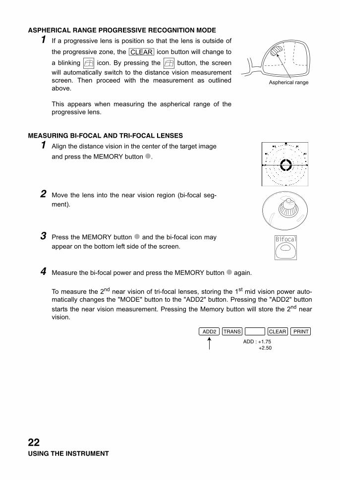
ASPHERICAL RANGE PROGRESSIVE RECOGNITION MODE
1 If a progressive lens is position so that the lens is outside of
the progressive zone, the icon button will change to
a blinking icon. By pressing the button, the screenwill automatically switch to the distance vision measurementscreen. Then proceed with the measurement as outlinedabove.
This appears when measuring the aspherical range of theprogressive lens.
MEASURING BI-FOCAL AND TRI-FOCAL LENSES
1 Align the distance vision in the center of the target imageand press the MEMORY button .
2 Move the lens into the near vision region (bi-focal seg-ment).
3 Press the MEMORY button and the bi-focal icon mayappear on the bottom left side of the screen.
4 Measure the bi-focal power and press the MEMORY button again.
To measure the 2nd near vision of tri-focal lenses, storing the 1st mid vision power auto-matically changes the "MODE" button to the "ADD2" button. Pressing the "ADD2" buttonstarts the near vision measurement. Pressing the Memory button will store the 2nd nearvision.
Aspherical range
CLEAR
22USING THE INSTRUMENT
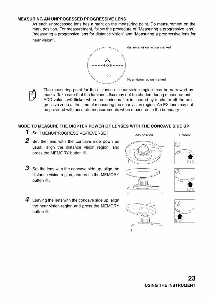
MEASURING AN UNPROCESSED PROGRESSIVE LENSAs each unprocessed lens has a mark on the measuring point. Do measurement on themark position. For measurement, follow the procedure of “Measuring a progressive lens”,“measuring a progressive lens for distance vision” and “Measuring a progressive lens fornear vision”.
MODE TO MEASURE THE DIOPTER POWER OF LENSES WITH THE CONCAVE SIDE UP
1 Set .
2 Set the lens with the concave side down asusual, align the distance vision region, andpress the MEMORY button .
3 Set the lens with the concave side up, align thedistance vision region, and press the MEMORYbutton .
4 Leaving the lens with the concave side up, alignthe near vision region and press the MEMORYbutton .
The measuring point for the distance or near vision region may be narrowed bymarks. Take care that the luminous flux may not be shaded during measurement. ADD values will flicker when the luminous flux is shaded by marks or off the pro-gressive zone at the time of measuring the near vision region. An EX lens may notbe provided with accurate measurements when measured in the boundary.
distance vision region marked
Near vision region marked
Lens position ScreenMENU/PROGRESSIVE/REVERSE
23USING THE INSTRUMENT
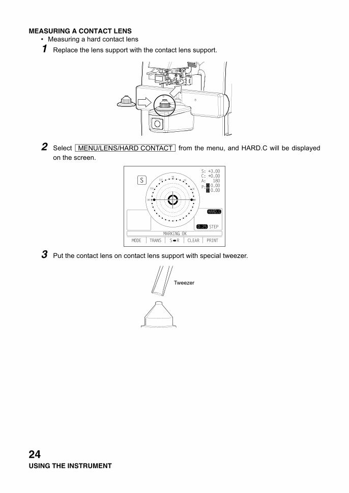
MEASURING A CONTACT LENS• Measuring a hard contact lens1 Replace the lens support with the contact lens support.
2 Select from the menu, and HARD.C will be displayedon the screen.
3 Put the contact lens on contact lens support with special tweezer.
MENU/LENS/HARD CONTACT
TweezerTweezer
24USING THE INSTRUMENT

• Measuring a soft contact lens without astigmatism
1 Use the contact lens support for measuring as measuring a hard contact lens.
2 Select and SOFT.C will be displayed on the screen.
3 Pinch the soft contact lens with special tweezers to remove moisture from the lens. Put
the lens between paper and move three times to remove moisture from the surface.
4 If there is moisture dews on the surface when the contact lens is held to the light, put thelens in the special solution again, and repeat the above. Moreover, take care about turninginside out. When in the normal position, the lens looks like a bowl. However, when thelens turns inside out, the rim looks warped. If the lens is ready for measurement, place iton the contact lens holder and observe the shape (with tweezers) for alignment. After 30seconds or more, the lens power changes since the internal moisture evaporates, there-fore, measure it as quickly as possible.
A:STEP MODESelect and press MODE button:
Press .
A soft contact lens cannot be accurately measured because of its structure.Although you can measure a soft contact lens power in following way, consider theresults an average and not the exact value.
If there is moisture on the soft contact lens surface, it is not possible to measurebecause the luminous flux malfunctions.
Use the hard contact mode when measuring a toric soft contact lens.
MENU/LENS/SOFT CONTACT
MENU/A:STEP/5
A:5
25USING THE INSTRUMENT
The axial angle is rounded to 5°. The unit's place blinks.It is convenient for inputting the result by doing measurement with the trial lens left in thetemporary frame.To reset, press below:
The 5° rounding is reset.
AXIS MARKING (CARTRIDGE SPECIFICATION/STEEL NEEDLE SPECIFICATION)
Using the cartridge, one light touch to the lens can put a clear ink mark.
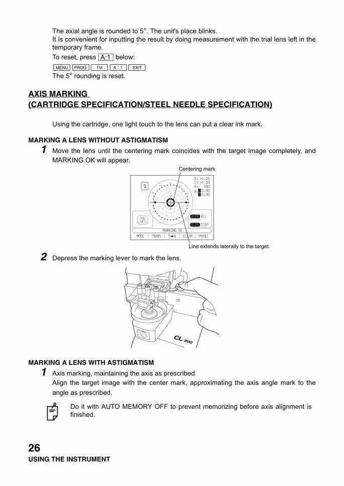
MARKING A LENS WITHOUT ASTIGMATISM
1 Move the lens until the centering mark coincides with the target image completely, andMARKING OK will appear.
2 Depress the marking lever to mark the lens.
MARKING A LENS WITH ASTIGMATISM
1 Axis marking, maintaining the axis as prescribedAlign the target image with the center mark, approximating the axis angle mark to theangle as prescribed.
Do it with AUTO MEMORY OFF to prevent memorizing before axis alignment isfinished.
A:1
Centering mark
Line extends laterally to the target.
26USING THE INSTRUMENT
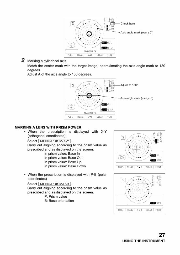
2 Marking a cylindrical axisMatch the center mark with the target image, approximating the axis angle mark to 180degrees.Adjust A of the axis angle to 180 degrees.
MARKING A LENS WITH PRISM POWER• When the prescription is displayed with X-Y
(orthogonal coordinates):Select .Carry out aligning according to the prism value asprescribed and as displayed on the screen.
in prism value: Base Inin prism value: Base Outin prism value: Base Upin prism value: Base Down
• When the prescription is displayed with P-B (polarcoordinates)Select .Carry out aligning according to the prism value asprescribed and as displayed on the screen.
P: Prism valueB: Base orientation
Check here
Axis angle mark (every 5°)
Adjust to 180°.
Axis angle mark (every 5°)
MENU/PRISM/X-Y
MENU/PRISM/P-B
27USING THE INSTRUMENT

PRINTING ADDITIONAL TEXTBOX (WITH PRINTER SPECIFICATION)
On the print out with the measuring data, the user can input his own text, like office name,address or special message. The available space is three line of 20 characters each.
Select and press the button below the icon , and the world ofmarking of text will appear (as shown at below).
: Moves to the left the cursor in Section A.: Moves to the right the cursor in Section A.: Moves to the left where to write in Section B.: Moves to the right where to write in Section B.: Writes the character in Section B.
Upon completing Section B, move the cursor to END of Section A and press , and writ-ing may be possible, returning the measurement screen. Once the characters are written,they will remain even after the instrument power is turned off.
Take care that the polar coordinates are not the same as the value on the angularscale in the target image.
• When the unit is mm.
Select .The marks show the optical centerreaches the center of measurement by movingthe lens in the arrow directions by the distanceas displayed.
3.0mm2.0mm
0 will be displayed if the spherical power S is around 0.
MENU/PRISM/mm
MENU/NAME/SETS
ection AS
ection B
(Characters to
be written)
1 2 3 4 5
12345
28USING THE INSTRUMENT
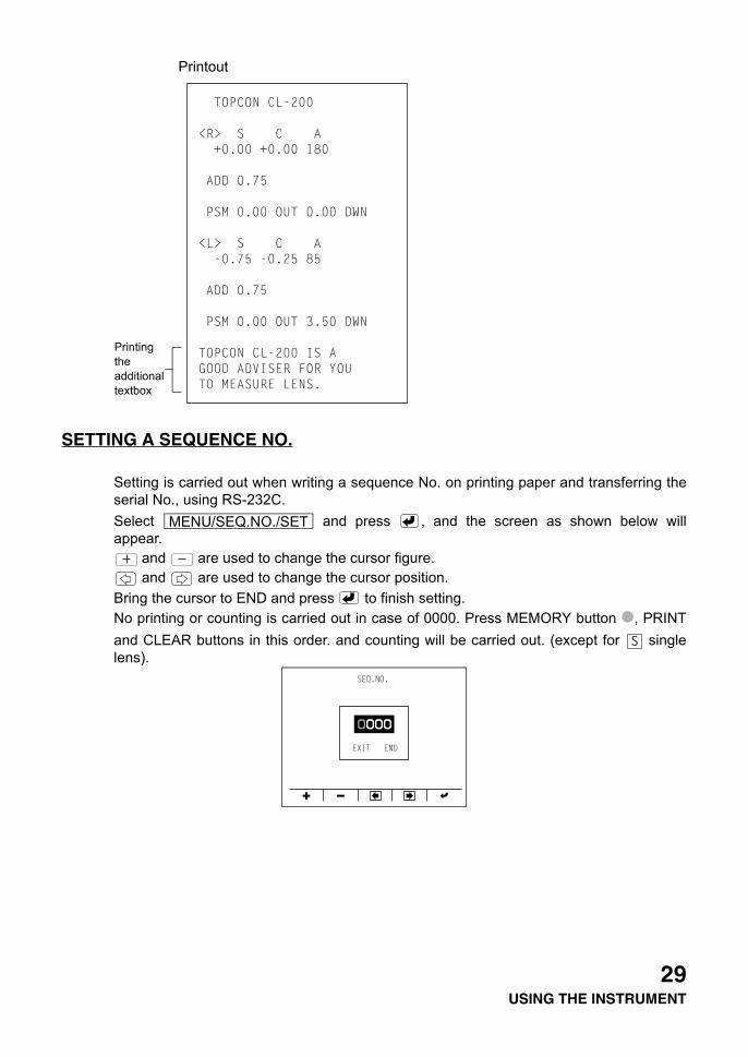
Printout
SETTING A SEQUENCE NO.
Setting is carried out when writing a sequence No. on printing paper and transferring theserial No., using RS-232C.Select and press , and the screen as shown below willappear.
and are used to change the cursor figure. and are used to change the cursor position.
Bring the cursor to END and press to finish setting.No printing or counting is carried out in case of 0000. Press MEMORY button , PRINTand CLEAR buttons in this order. and counting will be carried out. (except for singlelens).
Printing the additional textbox
MENU/SEQ.NO./SET
29USING THE INSTRUMENT
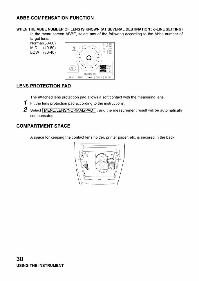
ABBE COMPENSATION FUNCTION
WHEN THE ABBE NUMBER OF LENS IS KNOWN:(AT SEVERAL DESTINATION : d-LINE SETTING)In the menu screen ABBE, select any of the following according to the Abbe number oftarget lens:Normal (50-60)MID (40-50)LOW (30-40)
LENS PROTECTION PAD
The attached lens protection pad allows a soft contact with the measuring lens.1 Fit the lens protection pad according to the instructions.
2 Select , and the measurement result will be automaticallycompensated.
COMPARTMENT SPACE
A space for keeping the contact lens holder, printer paper, etc. is secured in the back.
MENU/LENS/NORMAL(PAD)
30USING THE INSTRUMENT
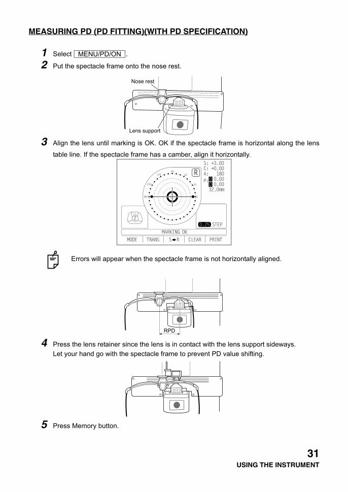
MEASURING PD (PD FITTING)(WITH PD SPECIFICATION)
1 Select .
2 Put the spectacle frame onto the nose rest.
3 Align the lens until marking is OK. OK if the spectacle frame is horizontal along the lens
table line. If the spectacle frame has a camber, align it horizontally.
4 Press the lens retainer since the lens is in contact with the lens support sideways.Let your hand go with the spectacle frame to prevent PD value shifting.
5 Press Memory button.
Errors will appear when the spectacle frame is not horizontally aligned.
MENU/PD/ON
Nose rest
Lens support
RPD
31USING THE INSTRUMENT

6 Follow the similar steps to measure the lens on the opposite side.Totaled PD will be displayed.
7 Bring the nose rest to the extreme right and fold it. It will stick to the lens table by means ofa magnet.Range 25 — 45mm on one side (minimum 0.5mm)
8 Difference may occur by the measurement technique and with low-power lenses having alarge camber angle.
If the measured PD value differs from that of marking PD.
No camber angle A camber angle
Since the optical center of the glasses mounted forthe infinite far is searched, the measured PD valueof CL-200 is called the PD/fitting value.
Marking
Principal point PD fitting(by PD mechanism)
Marking PD
0∆ flux
When the pupil is on the marking position in the case of a concave lens, a prism is added outside.
32USING THE INSTRUMENT
MAINTENANCE
AUTO SHUT-OFF
1 The monitor screen will shut off automatically if not in use for about 10 minutes.
2 Press any button to resume.
3 Select if it is not desirable.Press the button for 3 sec and longer, and the monitor screen goes OFF.
FUSE
1 The fuse holder is provided at the bottom of the instrument.
2 Disconnect the power cable.
3 The cap of fuse holder comes off when screwdriver truns the cap.
4 A glass tube fuse is provided in the holder.
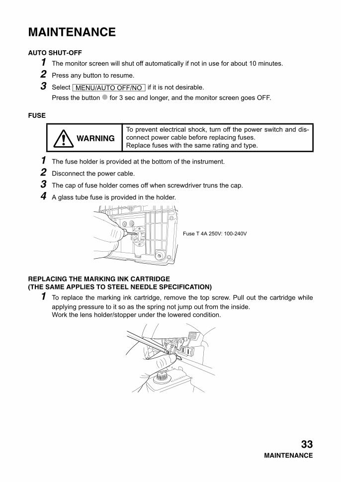
REPLACING THE MARKING INK CARTRIDGE (THE SAME APPLIES TO STEEL NEEDLE SPECIFICATION)
1 To replace the marking ink cartridge, remove the top screw. Pull out the cartridge whileapplying pressure to it so as the spring not jump out from the inside.Work the lens holder/stopper under the lowered condition.
WARNINGTo prevent electrical shock, turn off the power switch and dis-connect power cable before replacing fuses.Replace fuses with the same rating and type.
MENU/AUTO OFF/NO
Fuse T 4A 250V: 100-240V
33MAINTENANCE
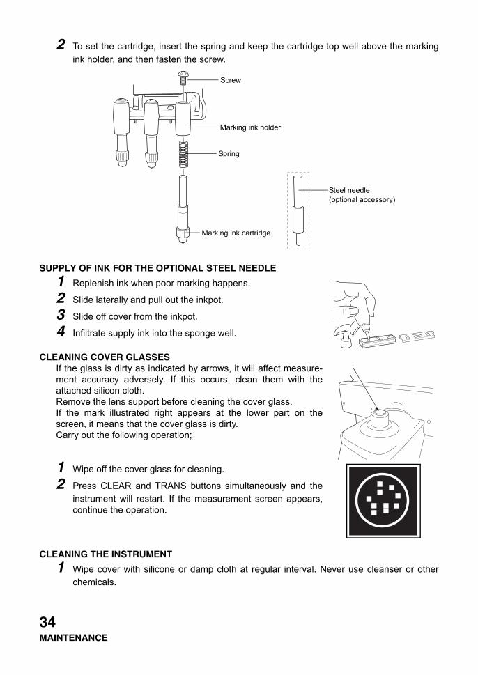
2 To set the cartridge, insert the spring and keep the cartridge top well above the markingink holder, and then fasten the screw.
SUPPLY OF INK FOR THE OPTIONAL STEEL NEEDLE
1 Replenish ink when poor marking happens.
2 Slide laterally and pull out the inkpot.
3 Slide off cover from the inkpot.
4 Infiltrate supply ink into the sponge well.
CLEANING COVER GLASSESIf the glass is dirty as indicated by arrows, it will affect measure-ment accuracy adversely. If this occurs, clean them with theattached silicon cloth.Remove the lens support before cleaning the cover glass.If the mark illustrated right appears at the lower part on thescreen, it means that the cover glass is dirty.Carry out the following operation;
1 Wipe off the cover glass for cleaning.
2 Press CLEAR and TRANS buttons simultaneously and theinstrument will restart. If the measurement screen appears,continue the operation.
CLEANING THE INSTRUMENT
1 Wipe cover with silicone or damp cloth at regular interval. Never use cleanser or otherchemicals.
Steel needle(optional accessory)
Screw
Marking ink holder
Spring
Marking ink cartridge
34MAINTENANCE
35BEFORE REQUESTING SERVICE
BEFORE REQUESTING SERVICE
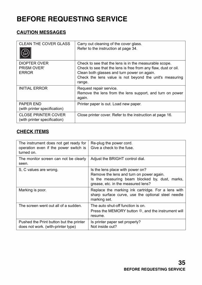
CAUTION MESSAGES
CHECK ITEMS
CLEAN THE COVER GLASS Carry out cleaning of the cover glass.Refer to the instruction at page 34.
DIOPTER OVERPRISM OVER'ERROR
Check to see that the lens is in the measurable scope.Check to see that the lens is free from any flaw, dust or oil.Clean both glasses and turn power on again.Check the lens value is not beyond the unit's measuringrange.
INITIAL ERROR Request repair service.Remove the lens from the lens support, and turn on poweragain.
PAPER END (with printer specification)
Printer paper is out. Load new paper.
CLOSE PRINTER COVER (with printer specification)
Close printer cover. Refer to the instruction at page 16.
The instrument does not get ready foroperation even if the power switch isturned on.
Re-plug the power cord.Give a check to the fuse.
The monitor screen can not be clearlyseen.
Adjust the BRIGHT control dial.
S, C values are wrong. Is the lens place with power on?Remove the lens and turn on power again.Is the measuring beam blocked by, dust, marks,grease, etc. in the measured lens?
Marking is poor. Replace the marking ink cartridge. For a lens withsharp surface curve, use the optional steel needlemarking set.
The screen went out all of a sudden. The auto shut-off function is on.Press the MEMORY button , and the instrument willresume.
Pushed the Print button but the printer does not work. (with-printer type)
Is printer paper set properly?Not inside out?
SPECIFICATIONS
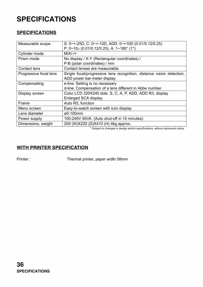
SPECIFICATIONS
WITH PRINTER SPECIFICATION
Printer : Thermal printer, paper width 58mm
Measurable scope S: 0~+-25D, C: 0~+-10D, ADD: 0~+10D (0.01/0.12/0.25)P: 0~10∆ (0.01/0.12/0.25), A: 1~180° (1°)
Cylinder mode MIX/-/+Prism mode No display / X-Y (Rectangular coordinates) /
P-B (polar coordinates) / mmContact lens Contact lenses are measurable.Progressive focal lens Single focal/progressive lens recognition, distance vision detection,
ADD power bar-meter displayCompensating e-line: Setting is no necessary
d-line: Compensation of a lens different in Abbe number.Display screen Color LCD 320X240 dots S, C, A, P, ADD, ADD R/L display
Enlarged SCA display.Frame Auto R/L functionMenu screen Easy-to-watch screen with icon displayLens diameter ø5-100mmPower supply 100-240V 50VA (Auto shut-off in 10 minutes)Dimensions, weight 200 (W)X220 (D)X410 (H) 4kg approx.
* Subject to changes in design and/or specifications, without advanced notice.
36SPECIFICATIONS
ELECTROMAGNETIC COMPATIBILITY
This product conforms to the EMC Standard (IEC 60601-1-2:2001).
a) MEDICAL ELECTRICAL EQUIPMENT needs special precautions regarding EMC and needs tobe installed and put into service according to the EMC information provided in the ACCOMPA-NYING DOCUMENTS.
b) Portable and mobile RF communications equipment can affect MEDICAL ELECTRICALEQUIPMENT.
c) The use of ACCESSORIES, transducers and cables other than those specified, with theexception of transducers and cables sold by the manufacturer of the EQUIPMENT or SYSTEMas replacement parts for internal components, may result in increased EMISSIONS ordecreased IMMUNITY of the EQUIPMENT or SYSTEM.
d) The EQUIPMENT or SYSTEM should not be used adjacent to or stacked with other equipment.IF adjacent or stacked use is necessary, the EQUIPMENT or SYSTEM should be observed toverify normal operation in the configuration in which it will be used.
e) The use of the ACCESSORY, transducer or cable with EQUIPMENT and SYSTEMS other thanthose specified may result in increased EMISSION or decreased IMMUNITY of the EQUIP-MENT or SYSTEM.
Item Article code Model No. Length(m)
RS-232C on-line cable 418120002 - 4.8USB CABLE (USB 2.0 Shielded) - - 1.7
Guidance and manufacturer's declaration - electromagnetic emissionsThe CL-200 is intended for use in the electromagnetic environment specified below.The customer or the user of the CL-200 should assure that it is used in such an environment.
Emissions test Compliance Electromagnetic environment - guidance
RF emissionsCISPR 11
Group 1 The CL-200 uses RF energy only for its internalfunction. Therefore, its RF emissions are very lowand are not likely to cause any interference innearby electronic equipment.
RF emissions CISPR 11
Class A The CL-200 is suitable for use in all establish-ments other than domestic and those directly con-nected to the public low-voltage power supplynetwork that supplies buildings used for domesticpurposes.
Harmonic emissions IEC61000-3-2
Class A
Voltage fluctuations/ flicker emissions IEC61000-3-3
Complies
37SPECIFICATIONS

Guidance and manufacturer's declaration - electromagnetic immunityThe CL-200 is intended for use in the electromagnetic environment specified below.The customer or the user of the CL-200 should assure that it is used in such an environment.
Immunity test IEC 60601test level
Compliance level
Electromagnetic environment - guidance
Electrostaticdischarge (ESD)IEC 61000-4-2
±6 kV contact
±8 kV air
±6 kV contact
±8 kV air
Floors should be wood, concreteor ceramic tile. If floors are cov-ered with synthetic material, therelative humidity should be atleast 30%.
Electrical fasttransient/burstIEC 61000-4-4
±2 kV for powersupply lines
±1 kV forinput/output lines
±2 kV for powersupply lines
±1 kV forinput/output lines
Mains power quality should bethat of a typical commercial orhospital environment.
SurgeIEC 61000-4-5
±1 kVdifferential mode
±2 kVcommon mode
±1 kVdifferential mode
±2 kVcommon mode
Mains power quality should bethat of a typical commercial orhospital environment.
Voltage dips, shortinterruptions andVoltage variationson power supplyinput linesIEC 61000-4-11
<5% Ut(>95% dip in Ut)for 0.5 cycle40% Ut(60% dip in Ut)for 5 cycles70% Ut(30% dip in Ut)for 25 cycles<5% Ut(>95% dip in Ut)for 5 sec.
<5% Ut (>95% dip in Ut)for 0.5 cycle40% Ut(60% dip in Ut)for 5 cycles70% Ut(30% dip in Ut)for 25 cycles<5% Ut(>95% dip in Ut)for 5 sec.
Mains power quality should bethat of a typical commercial orhospital environment. If the useror the CL-200 requires continuedoperation during power mainsinterruptions, it is recommendedthat the CL-200 be powered froman uninterruptible power supplyor battery.
Power frequency(50/60 Hz)magnetic fieldIEC 61000-4-8
3 A/m 3 A/m Power frequency magnetic fieldsshould be at levels characteristicof a typical location in a typicalcommercial or hospital environ-ment.
NOTE Ut is the a.c. mains voltage prior to application of the test level.
38SPECIFICATIONS
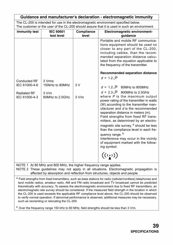
Guidance and manufacturer's declaration - electromagnetic immunityThe CL-200 is intended for use in the electromagnetic environment specified below.The customer or the user of the CL-200 should assure that it is used in such an environment.Immunity test IEC 60601
test levelCompliance
levelElectromagnetic environment-
guidance
Conducted RFIEC 61000-4-6
Radiated RFIEC 61000-4-3
3 Vrms150kHz to 80MHz
3 V/m80MHz to 2.5GHz
3 V
3 V/m
Portable and mobile RF communica-tions equipment should be used nocloser to any part of the CL-200,including cables, than the recom-mended separation distance calcu-lated from the equation applicable tothe frequency of the transmitter.
Recommended separation distance
80MHz to 800MHz 800MHz to 2.5GHz
where P is the maximum outputpower rating of the transmitter in watts(W) according to the transmitter man-ufacturer and d is the recommendedseparation distance in meters (m).Field strengths from fixed RF trans-mitters, as determined by an electro-magnetic site survey, a should be lessthan the compliance level in each fre-quency range. bInterference may occur in the vicinityof equipment marked with the follow-ing symbol:
NOTE 1 At 80 MHz and 800 MHz, the higher frequency range applies.NOTE 2 These guidelines may not apply in all situations. Electromagnetic propagation is
affected by absorption and reflection from structures, objects and people.a Field strengths from fixed transmitters, such as base stations for radio (cellular/cordless) telephones and
land mobile radios, amateur radio, AM and FM radio broadcast and TV broadcast cannot be predictedtheoretically with accuracy. To assess the electromagnetic environment due to fixed RF transmitters, anelectromagnetic site survey should be considered. If the measured field strength in the location in whichthe CL-200 is used exceeds the applicable RF compliance level above, the CL-200 should be observedto verify normal operation. If abnormal performance is observed, additional measures may be necessary,such as reorienting or relocating the CL-200.
b Over the frequency range 150 kHz to 80 MHz, field strengths should be less than 3 V/m.
d 1.2 P=
d 1.2 P=d 2.3 P=
39SPECIFICATIONS
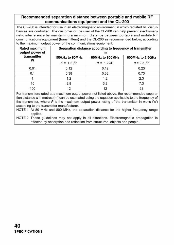
Recommended separation distance between portable and mobile RF communications equipment and the CL-200
The CL-200 is intended for use in an electromagnetic environment in which radiated RF distur-bances are controlled. The customer or the user of the CL-200 can help prevent electromag-netic interference by maintaining a minimum distance between portable and mobile RFcommunications equipment (transmitters) and the CL-200 as recommended below, accordingto the maximum output power of the communications equipment.
Rated maximum output power of
transmitterW
Separation distance according to frequency of transmitterm
150kHz to 80MHz 80MHz to 800MHz 800MHz to 2.5GHz
0.01 0.12 0.12 0.230.1 0.38 0.38 0.731 1.2 1.2 2.3
10 3.8 3.8 7.3100 12 12 23
For transmitters rated at a maximum output power not listed above, the recommended separa-tion distance d in metres (m) can be estimated using the equation applicable to the frequency ofthe transmitter, where P is the maximum output power rating of the transmitter in watts (W)according to the transmitter manufacturer.NOTE 1 At 80 MHz and 800 MHz, the separation distance for the higher frequency range
applies.NOTE 2 These guidelines may not apply in all situations. Electromagnetic propagation is
affected by absorption and reflection from structures, objects and people.
d 1.2 P= d 1.2 P= d = 2.3 P
40SPECIFICATIONS
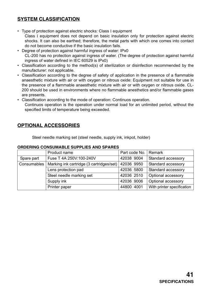
SYSTEM CLASSIFICATION
• Type of protection against electric shocks: Class I equipmentClass I equipment does not depend on basic insulation only for protection against electricshocks. It can also be earthed; therefore, the metal parts with which one comes into contactdo not become conductive if the basic insulation fails.
• Degree of protection against harmful ingress of water: IPx0CL-200 has no protection against ingress of water. (The degree of protection against harmfulingress of water defined in IEC 60529 is IPx0)
• Classification according to the method(s) of sterilization or disinfection recommended by themanufacturer: not applicable.
• Classification according to the degree of safety of application in the presence of a flammableanaesthetic mixture with air or with oxygen or nitrous oxide: Equipment not suitable for use inthe presence of a flammable anaesthetic mixture with air or with oxygen or nitrous oxide. CL-200 should be used in environments where no flammable anesthetics and/or flammable gasesare presents.
• Classification according to the mode of operation: Continuos operation.Continuos operation is the operation under normal load for an unlimited period, without thespecified limits of temperature being exceeded.
OPTIONAL ACCESSORIES
Steel needle marking set (steel needle, supply ink, inkpot, holder)
ORDERING CONSUMABLE SUPPLIES AND SPARESProduct name Part code No. Remark
Spare part Fuse T 4A 250V:100-240V 42038 9004 Standard accessoryConsumables Marking ink cartridge (3 cartridges/set) 42036 9950 Standard accessory
Lens protection pad 42036 5800 Standard accessorySteel needle marking set 42036 2510 Optional accessorySupply ink 42036 9006 Optional accessoryPrinter paper 44800 4001 With printer specification
41SPECIFICATIONS
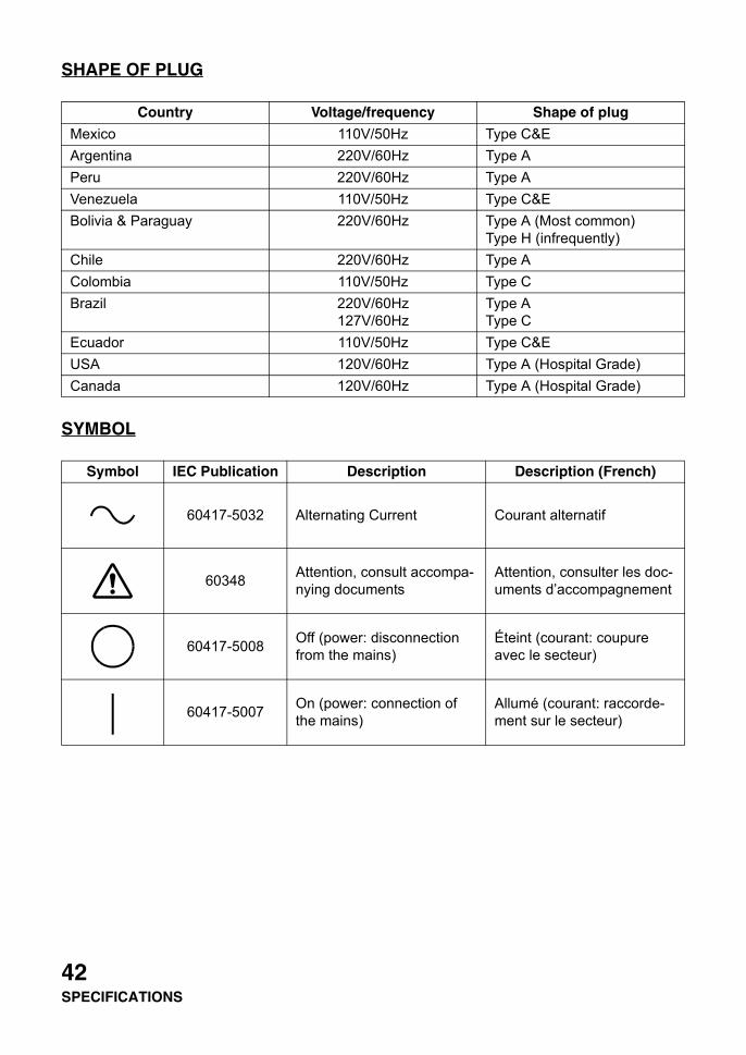
SHAPE OF PLUG
SYMBOL
Country Voltage/frequency Shape of plug
Mexico 110V/50Hz Type C&EArgentina 220V/60Hz Type APeru 220V/60Hz Type AVenezuela 110V/50Hz Type C&EBolivia & Paraguay 220V/60Hz Type A (Most common)
Type H (infrequently)Chile 220V/60Hz Type AColombia 110V/50Hz Type CBrazil 220V/60Hz
127V/60HzType AType C
Ecuador 110V/50Hz Type C&EUSA 120V/60Hz Type A (Hospital Grade)Canada 120V/60Hz Type A (Hospital Grade)
Symbol IEC Publication Description Description (French)
60417-5032 Alternating Current Courant alternatif
60348 Attention, consult accompa-nying documents
Attention, consulter les doc-uments d’accompagnement
60417-5008 Off (power: disconnection from the mains)
Éteint (courant: coupure avec le secteur)
60417-5007 On (power: connection of the mains)
Allumé (courant: raccorde-ment sur le secteur)
42SPECIFICATIONS
43USING THE INSTRUMENT AS A SYSTEM
USING THE INSTRUMENT AS A SYSTEM
ON - LINE SYSTEM
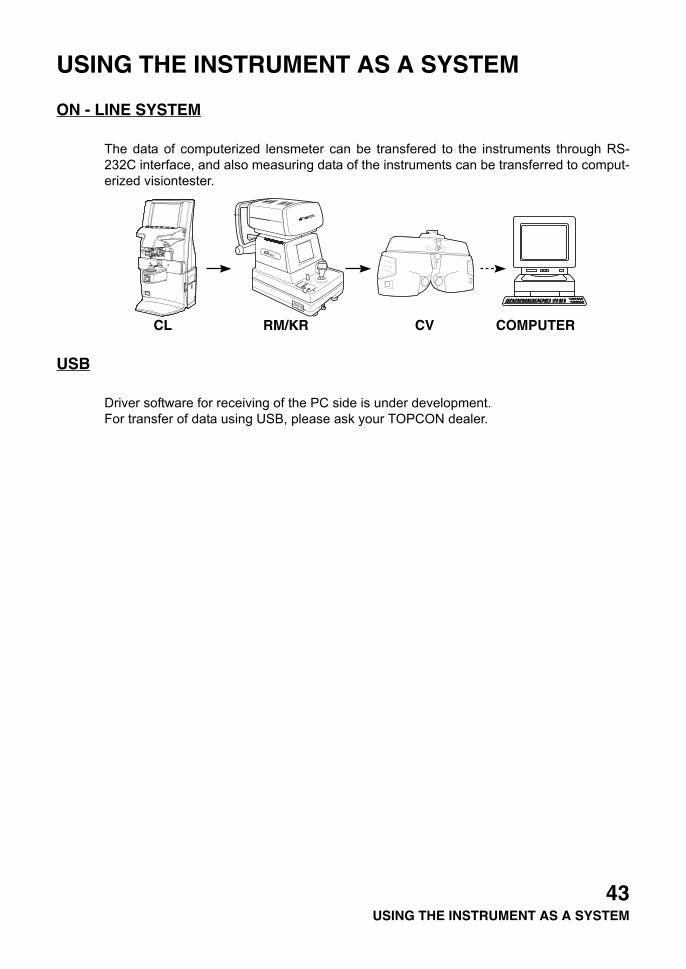
The data of computerized lensmeter can be transfered to the instruments through RS-232C interface, and also measuring data of the instruments can be transferred to comput-erized visiontester.
USB
Driver software for receiving of the PC side is under development.For transfer of data using USB, please ask your TOPCON dealer.
RK AUTO KERATO-REFRACTOMETER
.8800
When calling please give us the following information aboutyour unit:• Machine type: CL-200• Manufacturing No. (Shown on the rating plate on the back
of the instrument)• Period of Usage (Please give us the date of purchase).• Description of Problem (as detailed as possible).
COMPUTERIZED LENSMETER CL-200
INSTRUCTION MANUALVersion of 2006 (2006.04-500LW1)Date of issue: 1th, April, 2006
Published by TOPCON CORPORATION
75-1 Hasunuma-cho, Itabashi-ku, Tokyo, 174-8580 Japan.
©2004 TOPCON CORPORATION ALL RIGHTS RESERVED

CL-200
COMPUTERIZED LENSMETER
42039 91991
Printed in Japan 2006.04-500LW1


![Huvitz Auto Lensmeter HLM-9000 - Norwood Vision Group · [All New] HLM-9000 Auto Lensmeter Striving both accuracy in measurement and efficiency in operation at a time leads you to](https://img.pdfslide.us/doc/110x75/5f50f0cbb78a6552946849dd/huvitz-auto-lensmeter-hlm-9000-norwood-vision-all-new-hlm-9000-auto-lensmeter.jpg)