Embed Size (px)
Citation preview
FLZA4054
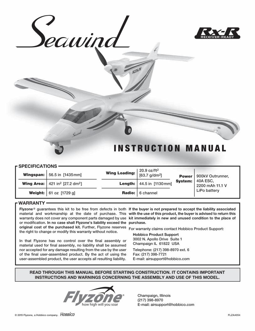
SPECIFICATIONS
PowerSystem:
900kV Outrunner,40A ESC,2200 mAh 11.1 VLiPo battery
Wing Loading:20.9 oz/ft2
[63.7 g/dm2]
Length: 44.5 in [1130mm]
Radio: 6 channel
Wingspan: 56.5 in [1435mm]
Wing Area: 421 in2 [27.2 dm2]
Weight: 61 oz [1729 g]
READ THROUGH THIS MANUAL BEFORE STARTING CONSTRUCTION. IT CONTAINS IMPORTANT
INSTRUCTIONS AND WARNINGS CONCERNING THE ASSEMBLY AND USE OF THIS MODEL.
READ THROUGH THIS MANUAL BEFORE STARTING CONSTRUCTION. IT CONTAINS IMPORTANT
INSTRUCTIONS AND WARNINGS CONCERNING THE ASSEMBLY AND USE OF THIS MODEL.
Flyzone ® guarantees this kit to be free from defects in both material and workmanship at the date of purchase. This warranty does not cover any component parts damaged by use or modification. In no case shall Flyzone’s liability exceed the
original cost of the purchased kit. Further, Flyzone reserves the right to change or modify this warranty without notice.
In that Flyzone has no control over the final assembly or material used for final assembly, no liability shall be assumed nor accepted for any damage resulting from the use by the user of the final user-assembled product. By the act of using the user-assembled product, the user accepts all resulting liability.
If the buyer is not prepared to accept the liability associated
with the use of this product, the buyer is advised to return this
kit immediately in new and unused condition to the place of
purchase.
For warranty claims contact Hobbico Product Support:
Hobbico Product Support
3002 N. Apollo Drive Suite 1Champaign IL 61822 USA
Telephone: (217) 398-8970 ext. 6Fax: (217) 398-7721E-mail: [email protected]
WARRANTY
I N S T R U C T I O N M A N U A L
© 2015 Flyzone, a Hobbico company.
® Champaign, Illinois(217) 398-8970E-mail: [email protected]
2
INTRODUCTION
Thank you for purchasing the Flyzone Seawind. The Flyzone Seawind is scaled after the popular full size Seawind. The retractable landing gear allows the plane to be fl own from your favorite runway or lake. The plane is quick to build so you can spend more time fl ying.
For the latest technical updates or manual corrections scan the QR code, or visit the Flyzone web site at www.fl yzoneplanes.com. Click the airplane icon at the top of the page, then select the Seawind when the airplane page opens. A “Tech Notice” box indicates corrected or updated technical information.
ADDITIONAL ITEMS REQUIRED
Radio System
To operate all the functions of the Flyzone Seawind (ailerons, elevator, throttle, rudder, fl aps and landing gear) a minimum of 6 channels is required. The lighting harness is connected to the fl ap channel. The Futaba 6J 6-channel 2.4GHz FHSS airplane radio (FUTK6000) or the Tactic TTX610 SLT transmitter (TACJ2610) and TR625 SLT receiver (TACL0625) are suitable and capable of operating all the functions.
LiPo Battery
A 3S 2200mAh LiPo battery is recommend to fl y the Seawind:
❍ 3S 11.1V 2200mAh 30C LiPo (GPMP0861)
For additional batteries more adhesive-back hook-&-loop Velcro is also required:
❍ Great Planes Velcro Hook & Loop 1x6" (GPMQ4480)
LiPo Charger
We recommend the DuraTrax® Onyx 235 AC/DC Advance Peak Charger (DTXP4235). The 235 features 110V AC or 12V DC input power, adjustable charge rate (to charge the recommended 2200 mAh batteries in as little as 30 minutes) and an LCD digital display screen (so you can see how much capacity it took to charge the battery – handy for calculating optimum fl ight time).
SAFETY PRECAUTIONS
Protect Your Model, Yourself & Others…
Follow These Important Safety Precautions
1. Your Seawind should not be considered a toy, but rather a sophisticated, working model that functions very much like a full-size airplane. Because of its performance capabilities, the Seawind, if not assembled and operated correctly, could possibly cause injury to yourself or spectators and damage to property.
2. You must assemble the Seawind according to the
instructions. Do not alter or modify the model, as doing so may result in an unsafe or unfl yable model. In a few cases the instructions may differ slightly from the photos. In those instances the written instructions should be considered as correct.
3. You must use an R/C radio system that is in good condition. All components must be correctly installed so that the model operates correctly on the ground and in the air. You must check the operation of the model and all components before every fl ight.
4. If you are not an experienced pilot or have not fl own this type of model before, we recommend that you get the assistance of an experienced pilot in your R/C club for your fi rst fl ights. If you’re not a member of a club, your local hobby shop has information about clubs in your area whose membership includes experienced pilots.
5. While this kit has been fl ight tested to exceed normal use, if the plane will be used for extremely high stress fl ying, such as racing, or if a battery larger than the one recommended is used, the modeler is responsible for taking steps to reinforce the high stress points and /or substituting hardware more suitable for the increased stress.
We, as the kit manufacturer, provide you with a top quality, thoroughly tested kit and instructions, but ultimately the quality and fl yability of your fi nished model depends on how you build it; therefore, we cannot in any way guarantee the performance of your completed model, and no representations are expressed or implied as to the performance or safety of your completed model.
ADDITIONAL ITEMS REQUIRED . . . . . . . . . . . . . . . . . . .2ASSEMBLE THE MODEL . . . . . . . . . . . . . . . . . . . . . . . . .3
Install the Main Landing Gear . . . . . . . . . . . . . . . . . . . .3Install the Horizontal Stabilizer . . . . . . . . . . . . . . . . . . .3Install the Wing Halves. . . . . . . . . . . . . . . . . . . . . . . . . .4Install the Receiver. . . . . . . . . . . . . . . . . . . . . . . . . . . . .5Set the Fail Safe . . . . . . . . . . . . . . . . . . . . . . . . . . . . . . .6Finish the Assembly . . . . . . . . . . . . . . . . . . . . . . . . . . . .6Check/Set the Control Throws . . . . . . . . . . . . . . . . . . .7Mount the Propeller . . . . . . . . . . . . . . . . . . . . . . . . . . . .7
Check the C.G. (Center of Gravity) . . . . . . . . . . . . . . . .8PREFLIGHT . . . . . . . . . . . . . . . . . . . . . . . . . . . . . . . . . . . .8
Identify Your Model . . . . . . . . . . . . . . . . . . . . . . . . . . . .8Ground Check and Range Check . . . . . . . . . . . . . . . . .8
ELECTRIC MOTOR SAFETY . . . . . . . . . . . . . . . . . . . . . .9FLIGHT TIPS . . . . . . . . . . . . . . . . . . . . . . . . . . . . . . . . . . .9
Takeoff . . . . . . . . . . . . . . . . . . . . . . . . . . . . . . . . . . . . . .9Flight . . . . . . . . . . . . . . . . . . . . . . . . . . . . . . . . . . . . . . . .9Landing. . . . . . . . . . . . . . . . . . . . . . . . . . . . . . . . . . . . . .9
REPLACEMENT PARTS . . . . . . . . . . . . . . . . . . . . . . . . .10
TABLE OF CONTENTS
3
Academy of Model Aeronautics
If you are not already a member of the AMA, please join! The AMA is the governing body of model aviation and membership provides liability insurance coverage, protects modelers’ rights and interests and is required to fl y at most R/C sites.
Academy of Model Aeronautics
5151 East Memorial DriveMuncie, IN 47302-9252
Tele. (800) 435-9262Fax (765) 741-0057
Or via the Internet at: http://www.modelaircraft.org
ASSEMBLE THE MODEL
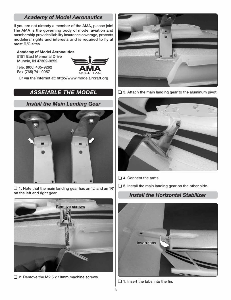
Install the Main Landing Gear
❑ 1. Note that the main landing gear has an ‘L’ and an ‘R’ on the left and right gear.
❑ 2. Remove the M2.5 x 10mm machine screws.
❑ 3. Attach the main landing gear to the aluminum pivot.
❑ 4. Connect the arms.
❑ 5. Install the main landing gear on the other side.
Install the Horizontal Stabilizer
❑ 1. Insert the tabs into the fi n.
4
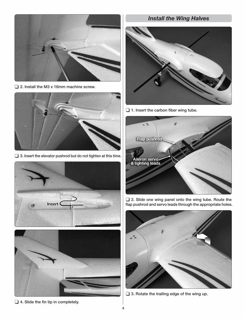
❑ 2. Install the M3 x 16mm machine screw.
❑ 3. Insert the elevator pushrod but do not tighten at this time.
❑ 4. Slide the fi n tip in completely.
Install the Wing Halves
❑ 1. Insert the carbon fi ber wing tube.
❑ 2. Slide one wing panel onto the wing tube. Route the fl ap pushrod and servo leads through the appropriate holes.
❑ 3. Rotate the trailing edge of the wing up.
5
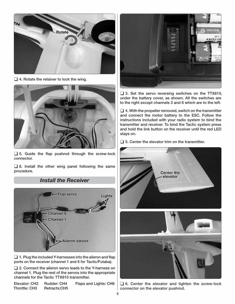
❑ 4. Rotate the retainer to lock the wing.
❑ 5. Guide the fl ap pushrod through the screw-lock connector.
❑ 6. Install the other wing panel following the same procedure.
Install the Receiver
❑ 1. Plug the included Y-harnesses into the aileron and fl ap ports on the receiver (channel 1 and 6 for Tactic/Futaba).
❑ 2. Connect the aileron servo leads to the Y-harness on channel 1. Plug the rest of the servos into the appropriate channels for the Tactic TTX610 transmitter.
Elevator: CH2 Rudder: CH4 Flaps and Lights: CH6Throttle: CH3 Retracts:CH5
❑ 3. Set the servo reversing switches on the TTX610, under the battery cover, as shown. All the switches are to the right except channels 3 and 6 which are to the left.
❑ 4. With the propeller removed, switch on the transmitter and connect the motor battery to the ESC. Follow the instructions included with your radio system to bind the transmitter and receiver. To bind the Tactic system press and hold the link button on the receiver until the red LED stays on.
❑ 5. Center the elevator trim on the transmitter.
❑ 6. Center the elevator and tighten the screw-lock connector on the elevator pushrod.
6
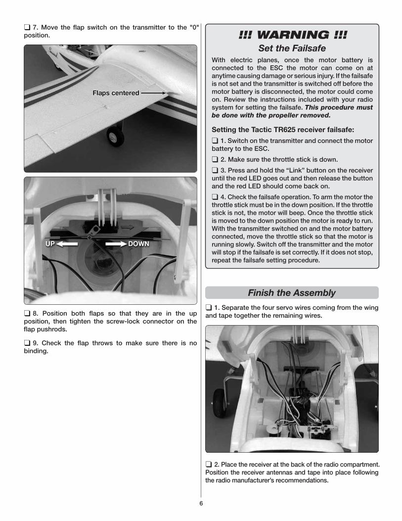
❑ 7. Move the fl ap switch on the transmitter to the "0" position.
❑ 8. Position both fl aps so that they are in the up position, then tighten the screw-lock connector on the fl ap pushrods.
❑ 9. Check the fl ap throws to make sure there is no binding.
!!! WARNING !!!Set the Failsafe
With electric planes, once the motor battery is connected to the ESC the motor can come on at anytime causing damage or serious injury. If the failsafe is not set and the transmitter is switched off before the motor battery is disconnected, the motor could come on. Review the instructions included with your radio system for setting the failsafe. This procedure must be done with the propeller removed.
Setting the Tactic TR625 receiver failsafe:
❑ 1. Switch on the transmitter and connect the motor battery to the ESC.
❑ 2. Make sure the throttle stick is down.
❑ 3. Press and hold the “Link” button on the receiver until the red LED goes out and then release the button and the red LED should come back on.
❑ 4. Check the failsafe operation. To arm the motor the throttle stick must be in the down position. If the throttle stick is not, the motor will beep. Once the throttle stick is moved to the down position the motor is ready to run. With the transmitter switched on and the motor battery connected, move the throttle stick so that the motor is running slowly. Switch off the transmitter and the motor will stop if the failsafe is set correctly. If it does not stop, repeat the failsafe setting procedure.
Finish the Assembly
❑ 1. Separate the four servo wires coming from the wing and tape together the remaining wires.
❑ 2. Place the receiver at the back of the radio compartment. Position the receiver antennas and tape into place following the radio manufacturer’s recommendations.
7
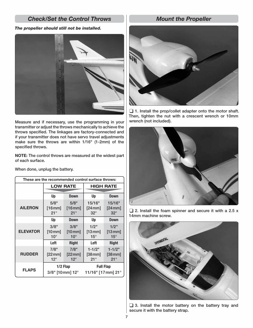
Check/Set the Control Throws
The propeller should still not be installed.
Measure and if necessary, use the programming in your transmitter or adjust the throws mechanically to achieve the throws specifi ed. The linkages are factory-connected and if your transmitter does not have servo travel adjustments make sure the throws are within 1/16" (1-2mm) of the specifi ed throws.
NOTE: The control throws are measured at the widest part of each surface.
When done, unplug the battery.
DownUp Up Down
3/8" [10mm] 12° FLAPS1/2 Flap
11/16" [17mm] 21° Full Flap
These are the recommended control surface throws:
5/8"[16mm]
21°
7/8"[22mm]
12°
3/8"[10mm]
10°
15/16"[24mm]
32°
1-1/2"[38mm]
21°
1/2"[13 mm]
15°
5/8"[16mm]
21°
7/8"[22mm]
12°
3/8"[10mm]
10°
15/16"[24mm]
32°
1-1/2"[38mm]
21°
1/2"[13 mm]
15°
AILERON
ELEVATOR
LOW RATE HIGH RATE
RUDDER
DownUp Up Down
RightLeft RightLeft
Mount the Propeller
❑ 1. Install the prop/collet adapter onto the motor shaft. Then, tighten the nut with a crescent wrench or 10mm wrench (not included).
❑ 2. Install the foam spinner and secure it with a 2.5 x 14mm machine screw.
❑ 3. Install the motor battery on the battery tray and secure it with the battery strap.
8
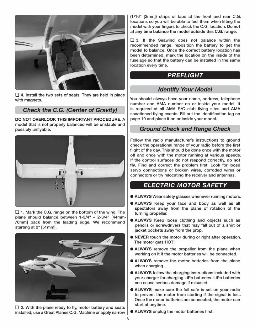
❑ 4. Install the two sets of seats. They are held in place with magnets.
Check the C.G. (Center of Gravity)
DO NOT OVERLOOK THIS IMPORTANT PROCEDURE. A model that is not properly balanced will be unstable and possibly unfl yable.
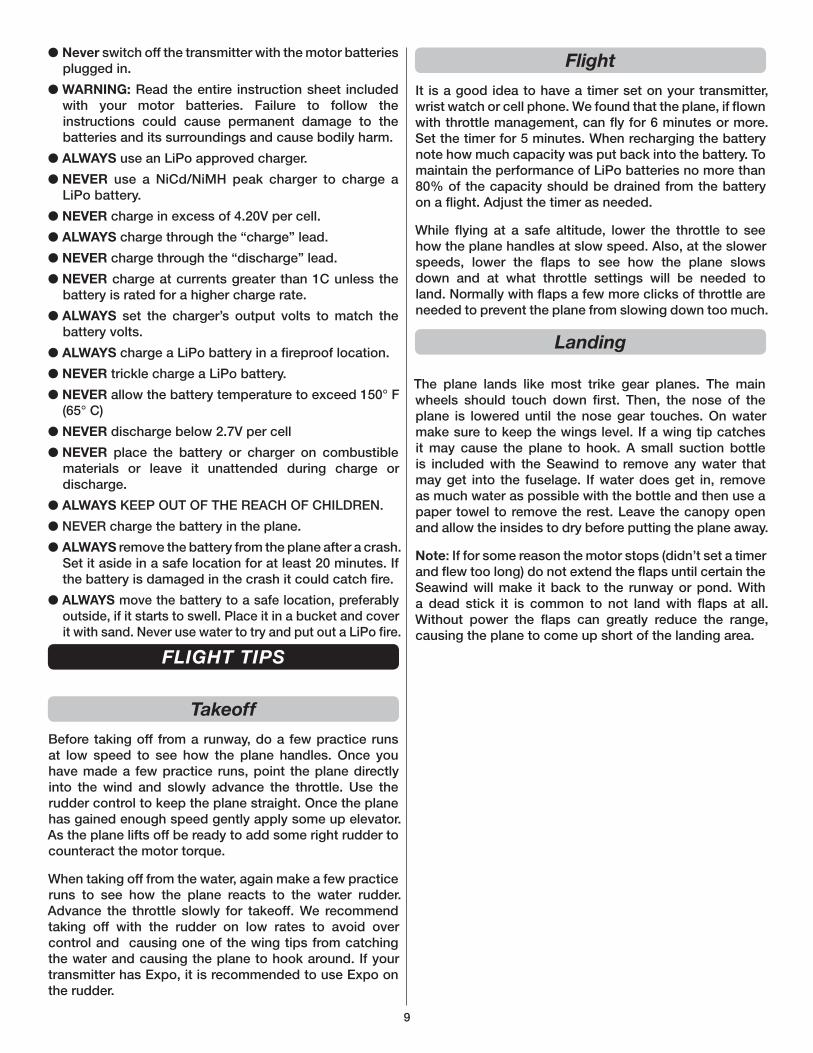
❑ 1. Mark the C.G. range on the bottom of the wing. The plane should balance between 1-3/4" – 2-3/4" [44mm-70mm] back from the leading edge. We recommend starting at 2" [51mm].
❑ 2. With the plane ready to fl y, motor battery and seats installed, use a Great Planes C.G. Machine or apply narrow
(1/16" [2mm]) strips of tape at the front and rear C.G. locations so you will be able to feel them when lifting the model with your fi ngers to check the C.G. location. Do not
at any time balance the model outside this C.G. range.
❑ 3. If the Seawind does not balance within the recommended range, reposition the battery to get the model to balance. Once the correct battery location has been determined, mark the location on the inside of the fuselage so that the battery can be installed in the same location every time.
PREFLIGHT
Identify Your Model
You should always have your name, address, telephone number and AMA number on or inside your model. It is required at all AMA R/C club fl ying sites and AMA sanctioned fl ying events. Fill out the identifi cation tag on page 10 and place it on or inside your model.
Ground Check and Range Check
Follow the radio manufacturer’s instructions to ground check the operational range of your radio before the fi rst fl ight of the day. This should be done once with the motor off and once with the motor running at various speeds. If the control surfaces do not respond correctly, do not
fl y. Find and correct the problem fi rst. Look for loose servo connections or broken wires, corroded wires or connectors or try relocating the receiver and antennas.
ELECTRIC MOTOR SAFETY
● ALWAYS Wear safety glasses whenever running motors.
● ALWAYS Keep your face and body as well as all spectators away from the plane of rotation of the turning propeller.
● ALWAYS Keep loose clothing and objects such as pencils or screwdrivers that may fall out of a shirt or jacket pockets away from the prop.
● NEVER touch the motor during or right after operation. The motor gets HOT!
● ALWAYS remove the propeller from the plane when working on it if the motor batteries will be connected.
● ALWAYS remove the motor batteries from the plane when charging.
● ALWAYS follow the charging instructions included with your charger for charging LiPo batteries. LiPo batteries can cause serious damage if misused.
● ALWAYS make sure the fail safe is set on your radio to prevent the motor from starting if the signal is lost. Once the motor batteries are connected, the motor can start at anytime.
● ALWAYS unplug the motor batteries fi rst.
9
● Never switch off the transmitter with the motor batteries plugged in.
● WARNING: Read the entire instruction sheet included with your motor batteries. Failure to follow the instructions could cause permanent damage to the batteries and its surroundings and cause bodily harm.
● ALWAYS use an LiPo approved charger.
● NEVER use a NiCd/NiMH peak charger to charge a LiPo battery.
● NEVER charge in excess of 4.20V per cell.
● ALWAYS charge through the “charge” lead.
● NEVER charge through the “discharge” lead.
● NEVER charge at currents greater than 1C unless the battery is rated for a higher charge rate.
● ALWAYS set the charger’s output volts to match the battery volts.
● ALWAYS charge a LiPo battery in a fi reproof location.
● NEVER trickle charge a LiPo battery.
● NEVER allow the battery temperature to exceed 150° F (65° C)
● NEVER discharge below 2.7V per cell
● NEVER place the battery or charger on combustible materials or leave it unattended during charge or discharge.
● ALWAYS KEEP OUT OF THE REACH OF CHILDREN.
● NEVER charge the battery in the plane.
● ALWAYS remove the battery from the plane after a crash. Set it aside in a safe location for at least 20 minutes. If the battery is damaged in the crash it could catch fi re.
● ALWAYS move the battery to a safe location, preferably outside, if it starts to swell. Place it in a bucket and cover it with sand. Never use water to try and put out a LiPo fi re.
FLIGHT TIPS
Takeoff
Before taking off from a runway, do a few practice runs at low speed to see how the plane handles. Once you have made a few practice runs, point the plane directly into the wind and slowly advance the throttle. Use the rudder control to keep the plane straight. Once the plane has gained enough speed gently apply some up elevator. As the plane lifts off be ready to add some right rudder to counteract the motor torque.
When taking off from the water, again make a few practice runs to see how the plane reacts to the water rudder. Advance the throttle slowly for takeoff. We recommend taking off with the rudder on low rates to avoid over control and causing one of the wing tips from catching the water and causing the plane to hook around. If your transmitter has Expo, it is recommended to use Expo on the rudder.
Flight
It is a good idea to have a timer set on your transmitter, wrist watch or cell phone. We found that the plane, if fl own with throttle management, can fl y for 6 minutes or more. Set the timer for 5 minutes. When recharging the battery note how much capacity was put back into the battery. To maintain the performance of LiPo batteries no more than 80% of the capacity should be drained from the battery on a fl ight. Adjust the timer as needed.
While fl ying at a safe altitude, lower the throttle to see how the plane handles at slow speed. Also, at the slower speeds, lower the fl aps to see how the plane slows down and at what throttle settings will be needed to land. Normally with fl aps a few more clicks of throttle are needed to prevent the plane from slowing down too much.
Landing
The plane lands like most trike gear planes. The main wheels should touch down fi rst. Then, the nose of the plane is lowered until the nose gear touches. On water make sure to keep the wings level. If a wing tip catches it may cause the plane to hook. A small suction bottle is included with the Seawind to remove any water that may get into the fuselage. If water does get in, remove as much water as possible with the bottle and then use a paper towel to remove the rest. Leave the canopy open and allow the insides to dry before putting the plane away.
Note: If for some reason the motor stops (didn’t set a timer and fl ew too long) do not extend the fl aps until certain the Seawind will make it back to the runway or pond. With a dead stick it is common to not land with fl aps at all. Without power the fl aps can greatly reduce the range, causing the plane to come up short of the landing area.

10
REPLACEMENT PARTS
Replacement parts may be purchased from your local hobby dealer or on-line. For assistance with defective or missing parts contact Hobbico Product Support at the contact information on the front cover of this manual.
FLZA6026 BRUSHLESS MOTOR 41-19-900kVFLZA6061 9g MICRO SERVOFLZA6214 PROP ADAPTERFLZA6576 40A ELECTRONIC SPEED CONTROLFLZA6578 MOTOR MOUNTFLZA6579 17g NOSE WHEEL RETRACT SERVOFLZA6580 36g MAIN GEAR RETRACT SERVOFLZA6640 WING SETFLZA6641 FUSELAGEFLZA6642 HORIZONTAL STABFLZA6643 VERTICAL FINFLZA6644 COCKPIT SEATFLZA6645 CANOPY SUPPORTFLZA6646 CANOPYFLZA6647 LIGHT PCBFLZA6648 MIXERFLZA6649 Y-HARNESSFLZA6650 REAR RETRACTSFLZA6651 FRONT RETRACTSFLZA6652 WHEELS ONLYFLZA6653 COWLFLZA6654 SPINNERFLZA6655 WATER RUDDERFLZA6656 WING JOINERFLZA6657 PROP 11.5X6
Fill out this tag and tape it inside your Seawind:
This model belongs to:
Name
Address
City, State, Zip
Phone Number
AMA Number

11

®


![Vectored Thrust Flying Wing - Hobbicomanuals.hobbico.com/flz/flza3612-14-manual.pdf · Vectored Thrust Flying Wing ... Weight: 29.6 – 31.3 oz [840 – 885 g] Wing Loading: 10.4](https://img.pdfslide.us/doc/110x75/5af1af897f8b9a8b4c8f147a/vectored-thrust-flying-wing-thrust-flying-wing-weight-296-313-oz-840.jpg)