Embed Size (px)
Citation preview

inSTrucTiOn manuaLcHain Saw
600sx
WARNINGRead the instructions carefully and follow the rules for safe operation.Failure to do so could result in serious injury.
X750-026 02 0X750 326-420 0
echo, incorporated400 Oakwood Road, Lake Zurich, Illinois 60047-1564Phone : 847-540-8400
1506Brh 0200 ESPrinted in Japan
Copyright © 2015 All Rights Reserved.
The engine exhaust from this product contains chemicals known to the State of California to cause
cancer, birth defects or other reproductive harm.
WARNING
1 600sx
RULES FOR SAFE OPERATIONA. Kickback Safety Precautions for Chain Saw Users
1. With a basic understanding of kickback, you can reduce or eliminate the element of surprise. Sudden surprise contributes to accidents.
2. Keep a good firm grip on the saw with both hands, the right hand on the rear handle, and the left hand on the front handle, when the engine is running. Use a firm grip with thumbs and fingers encircling the chain saw handles. A firm grip will help you reduce kickback and maintain control of the saw. Don’t let go.
3. Make sure that the area in which you are cutting is free from obstructions. Do not let the nose of the guide bar contact a log, branch, or any other obstruction which could be hit while you are operating the saw.
4. Cut at high engine speeds.
5. Do not overreach or cut above shoulder height.
6. Follow manufacturer’s sharpening and maintenance instructions for the saw chain.
7. Only use replacement bars and chains specified by the manufacturer or the equivalent.
WARNING!
KICKBACK may occur when the nose or tip of the guide bar touches an object, or when the wood closes in and pinches the saw chain in the cut.
Tip contact in some cases may cause a lightning fast reverse REACTION, Kicking the guide bar up and back towards the operator. Pinching the saw chain along the top of the guide bar may push the guide bar rapidly back towards the operator. Either of these reactions may cause you to lose control of the saw which could result in serious personal injury.
The Kick Guard® device is not installed on the guide bar when you purchase your shindaiwa chain saw. The Kick Guard® can be used in a majority of cutting operations, and is especially recommended for beginners, homeowners, or chain saw novices. Most cutting operations can be accomplished with the Kick Guard® in place.
Do not rely exclusively upon the safety devices built into your saw. As a chain saw user, you should take several steps to keep your cutting jobs free from accident or injury.
2600sx
1. Do not operate a chain saw with one hand! Serious injury to the operator, helpers, bystanders, or any combination of these persons may result from one-handed operation. A chain saw is intended for two-handed use.
2. Do not operate a chain saw when you are fatigued.
3. Use safety footwear, snug-fitting clothing and protective gloves. Wear eye, hearing, and head protection devices.
4. Use caution when handling fuel. Move the chain saw at least 3 m (10 feet) from the fueling point before starting the engine.
5. Do not allow other persons to be near the chain saw when starting or cutting with the chain saw. Keep bystanders and animals out of the work area.
6. Do not start cutting until you have a clear work area, secure footing, and a planned retreat path from the falling tree.
7. Keep all parts of your body away from the saw chain when the engine is running.
8. Before you start the engine, make sure that the saw chain is not contacting anything.
9. Carry the chain saw with the engine stopped, the guide bar and saw chain to the rear, and the muffler away from your body. When carrying a chain saw with the engine running, push the front hand guard forward to engage the chain brake.
10. Do not operate a chain saw that is damaged, improperly adjusted, or not completely and securely assembled. Be sure that the saw chain stops moving when the throttle control trigger is released.
11. Shut off the engine before setting the chain saw down.
12. Use extreme caution when cutting small size brush and saplings because slender material may catch the saw chain and be whipped toward you or pull you off balance.
13. When cutting a limb that is under tension, be alert for spring-back so that you will not be struck when the tension in the wood fibers is released.
14. Keep the handles dry, clean, and free of oil or fuel mixture.
15. Operate the chain saw only in well ventilated areas.
16. Do not operate a chain saw in a tree unless you have been specifically trained to do so.
17. All chain saw service, other than items listed in the Instruction manual maintenance instructions, should be performed by competent service personnel. (For example, if improper tools are used to remove the flywheel or if an improper tool is used to hold the flywheel in order to remove the clutch, structural damage to the flywheel could occur and could subsequently cause the flywheel to burst.)
18. When transporting your chain saw, use the appropriate guide bar scabbard.
19. Spark arrestor mufflers approved to SAE Standard J335 are standard on shindaiwa chain saws to reduce the possibility of forest fires. Do not operate the chain saw with a loose or defective muffler. Do not remove the spark arrestor screen.
B. Other Safety Precautions
3 600sx
WARNINGThe safety alert symbol accompanied by the word “WARNING” calls attention to an act or condition which CAN lead to serious personal injury or death if not avoided.
CAUTIONThe safety alert symbol accompanied by the word “CAUTION” calls attention to an act or condition which may lead to minor or moderate personal injury if not avoided.
NOTICEThis enclosed message provides tips for use, care and maintenance of the unit.
IMPORTANTThe enclosed message provides information necessary for the protection of the unit.
DANGERThe safety alert symbol accompanied by the word “DANGER” calls attention to an act or condition which WILL lead to serious personal injury or death if not avoided.
SYMBOLS AND SIGNS
CONTENTSRULES FOR SAFE OPERATION ............................................................................ 1SYMBOLS AND SIGNS ........................................................................................... 3PACKING LIST ......................................................................................................... 5NOMENCLATURE OF PARTS ................................................................................ 6OPERATOR SAFETY .............................................................................................. 8CORRECT USE OF CHAIN BRAKE ........................................................................ 9PREPARATION FOR USE ....................................................................................... 10FUEL AND LUBRICANT .......................................................................................... 12EMISSION DATA ..................................................................................................... 14OPERATION ............................................................................................................ 15CUTTING INSTRUCTION ........................................................................................ 18CHAIN AND GUIDE BAR COMBINATION ............................................................... 23MAINTENANCE AND CARE .................................................................................... 24SETTING THE SAW CHAIN .................................................................................... 28TROUBLESHOOTING ............................................................................................. 30STORAGE AFTER USE ........................................................................................... 31TECHNICAL DATA ................................................................................................... 32WARRANTY STATEMENTS .................................................................................... 33WARRANTY REGISTRATION SHEET .................................................................... 35
This chain saw is designed for cutting wood or wood products. Do not cut solid metal, sheet metal, plastic or any non-wood materials.
Specifications, descriptions and illustrative material in this literature are as accurate as known at the time of publication, but are subject to change without notice. Illustrations may include optional equipment and accessories, and may not include all standard equipment.
CIRCLE AND SLASH SYMBOLThis symbol means the specific action shown is prohibited. Ignoring these prohibitions can result in serious or fatal injury.
4600sx
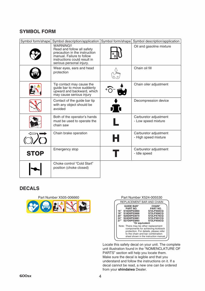
SYMBOL FORM
Locate this safety decal on your unit. The complete unit illustration found in the “NOMENCLATURE OF PARTS” section will help you locate them. Make sure the decal is legible and that you understand and follow the instructions on it. If a decal cannot be read, a new one can be ordered from your shindaiwa Dealer.
DECALS
Part Number X524-005530Part Number X505-006660
Symbol form/shape Symbol description/application Symbol form/shape Symbol description/applicationWARNING!! Read and follow all safety precaution in the instruction manual. Failure to follow instructions could result in serious personal injury.
Oil and gasoline mixture
Wear eyes, ears and head protection
Chain oil fill
Tip contact may cause the guide bar to move suddenly upward and backward, which may cause serious injury
Chain oiler adjustment
Contact of the guide bar tip with any object should be avoided
Decompression device
Both of the operator’s hands must be used to operate the chain saw L
Carburetor adjustment - Low speed mixture
Chain brake operation
HCarburetor adjustment - High speed mixture
STOPEmergency stop
TCarburetor adjustment - Idle speed
Choke control “Cold Start” position (choke closed)
REPLACEMENT BAR AND CHAIN GUIDE BAR* CHAIN* PART NO. PART NO.16” S16D0PS3860 S72LPX60CQ18” S18D0PS3866 S72LPX66CQ20” S20D0PS3870 S72LPX70CQ24” S24D0PS3881 S72LPX81CQ27” S27D0PS3893 S72LPX93CQ
*Or equivalentNote: There may be other replacement
components for achieving kickback protection. For details, please refer to the chain and bar combination sheet shown in the instruction manual.
5 600sx
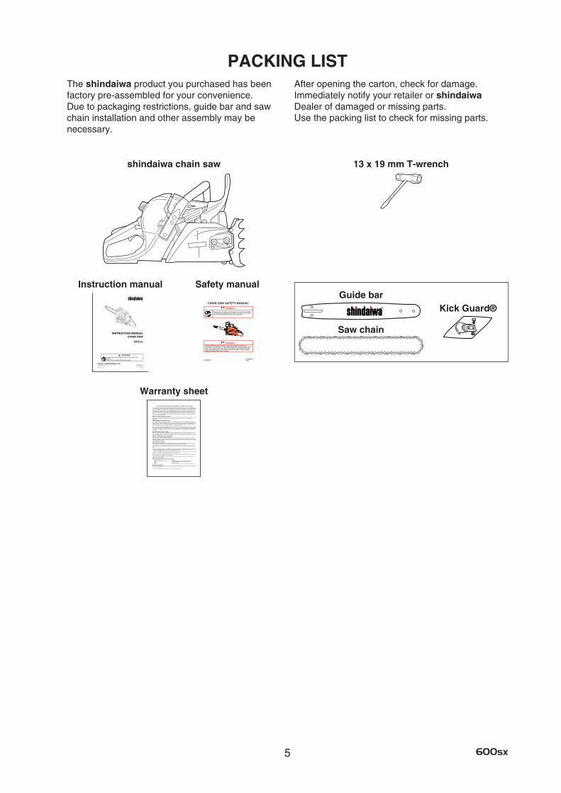
PACKING LISTThe shindaiwa product you purchased has been factory pre-assembled for your convenience. Due to packaging restrictions, guide bar and saw chain installation and other assembly may be necessary.
After opening the carton, check for damage. Immediately notify your retailer or shindaiwa Dealer of damaged or missing parts. Use the packing list to check for missing parts.
13 x 19 mm T-wrench
Instruction manual Safety manual
shindaiwa chain saw
Saw chain
Guide barKick Guard®
Warranty sheet
• •• •• •• •• •
6600sx
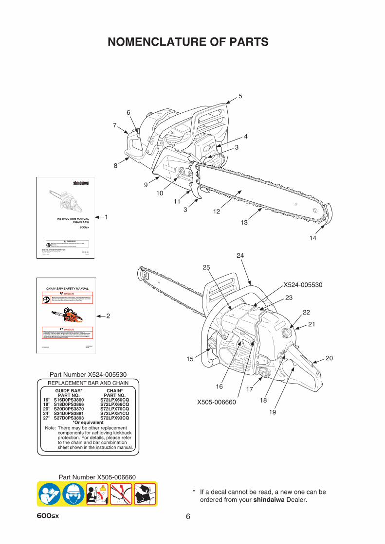
NOMENCLATURE OF PARTS
* If a decal cannot be read, a new one can be ordered from your shindaiwa Dealer.
19
14
15
1716
5
4
8
7
1011
12
3
2
1
X524-005530
9
21
6
22
20
23
18
13
3
24
25
X505-006660
Part Number X505-006660
Part Number X524-005530REPLACEMENT BAR AND CHAIN
GUIDE BAR* CHAIN* PART NO. PART NO.16” S16D0PS3860 S72LPX60CQ18” S18D0PS3866 S72LPX66CQ20” S20D0PS3870 S72LPX70CQ24” S24D0PS3881 S72LPX81CQ27” S27D0PS3893 S72LPX93CQ
*Or equivalentNote: There may be other replacement
components for achieving kickback protection. For details, please refer to the chain and bar combination sheet shown in the instruction manual.

7 600sx
1. Instruction manual - Included with unit.
Read before operation and keep for future
reference to learn proper, safe operating
techniques.
2. Safety manual - Describe operating and safety
instructions for this chain saw.
3. Spiked bumpers - Device, fitted in front of the
guide bar mounting point, acting as a pivot
when in contact with a tree or log.
4. Spark arrestor muffler - The spark arrestor
muffler controls the exhaust noise and
prevents hot, glowing particles of carbon
from leaving the muffler.
5. Front hand guard - Guard between the front
handle and the saw chain for protecting the
hand from injuries and aiding in control of the
chain saw if the hand slips off the handle.
This guard is used to lock the chain brake
which is to stop the saw chain rotation.
6. Choke control knob - Device for enriching the
fuel/air mixture in the carburetor to aid cold
starting.
Also activates fast idle throttle latch.
7. Rear handle (for the right hand) - Support
handle located towards the rear of the
engine housing.
8. Rear hand guard - Extension on the lower part
of the rear handle for protecting the hand
from the chain if it breaks or degrooves.
9. Clutch cover - Protective cover to the guide
bar, saw chain, clutch and sprocket when
the chain saw is in use.
10. Chain tension adjuster - Device to adjust
chain tension.
11. Chain catcher - A projection designed to
reduce the risk of the operator’s right hand
from being hit by a chain which has broken
or derailed from the guide bar during cutting.
NOMENCLATURE OF PARTS 12. Guide bar - The part that supports and guides
the saw chain.
13. Saw chain - Chain, serving as a cutting tool.
14. Bar tip guard - Anti-kickback device attached
on the bar nose.
15. Oil tank cap - For closing the oil tank.
16. Starter handle - Pull handle slowly until starter
engages then quickly and firmly.
When engine starts, return handle slowly.
Do not let handle snap back or damage to
unit will occur.
17. Fuel tank cap - For closing the fuel tank.
18. Ignition switch - Device for connecting and
disconnecting the ignition system and thus
allowing the engine to be started or stopped.
19. Throttle trigger - Device activated by the
operator’s finger, for controlling the engine
speed.
20. Throttle trigger lockout - A safety lever which
must be depressed before the throttle trigger
can be activated in order to prevent the
accidental operation of the throttle trigger.
21. Air cleaner cover - Covers air cleaner.
22. Cleaner cover knob - Device for installing the
air cleaner cover.
23. Decompression device - Device for lowering
the compression in the cylinder, to aid
starting.
24. Front handle (for the left hand) - Support
handle located at the front of the engine
housing.
25. Cylinder cover - The cooling airflow grill.
It covers the cylinder, spark plug and
silencer.
8600sx
OPERATOR SAFETYVIBRATION AND COLD• ItisbelievedthataconditioncalledRaynaud’s
Phenomenon, which affects the fingers of certain individuals, may be brought about by exposure to vibration and cold. Exposure to vibration and cold may cause tingling and burning followed by loss of color and numbness in the fingers. The following precautions are strongly recommended because the minimum exposure which might trigger the ailment is unknown.
• Keepyourbodywarm,especiallytheheadandneck, feet and ankles and hands and wrists.
• Maintaingoodbloodcirculationbyperformingvigorous arm exercises during frequent work breaks and also by not smoking.
• Limitthenumberofhoursofoperation. Try to fill each day with jobs where operating the chain saw, or other hand-held power equipment is not required.
• Ifyouexperiencediscomfortrednessand swelling of the fingers, followed by whitening and loss of feeling, consult your physician before further exposing yourself to cold and vibration.
REPETITIVE STRESS INJURY• Itisbelievedthatover-usingthemusclesand
tendons of the finger, hands, arms and shoulders may cause soreness, swelling, numbness, weakness and extreme pain to the areas just mentioned. Certain repetitive hand activities may put you at a high risk for developing a repetitive stress injury (RSI).
• AnextremeRSIconditionisCarpalTunnelSyndrome (CTS) which could occur when your wrist swells and squeezes a vital nerve that runs through the area. Some believe that prolonged exposure to vibration may contribute to CTS. CTS can cause severe pain for months or even years.
To reduce the risk of RSI/CTS, do the following:
• Avoidusingyourwristinabent,extendedortwisted position.
• Takeperiodicbreakstominimizerepetitionandrest your hands.
• Reducethespeedandforceinwhichyoudotherepetitive movement.
• Doexercisestostrengthenhandandarmmuscles.
• Seeadoctorifyoufeeltingling,numbnessorpain in your fingers, hands, wrists or arms. The sooner RSI/CTS is diagnosed, the more likely permanent nerve and muscle damage can be prevented.
EYE AND HEARING PROTECTION• WeareyeprotectiongogglesthatmeetANSI
Z 87.1 requirements. Goggles meeting the requirements have the mark “Z 87” stamped on them.
• Wearhearingprotection. If this guideline is not followed, hearing loss can occur. shindaiwa recommends wearing hearing protection at all times.
WEAR PROPER CLOTHING• Snugfittingdurableclothingshouldbeworn.
Pants should have long legs, do not wear shorts. Do not wear loose fitting clothing, scarves, neckties, jewelry or any item that may become tangled in surrounding growth or the chain saw itself.
• Wearshoeswithnon-skidsoles. Do not wear open toed shoes or operate unit barefooted.
• Wearno-slip,heavydutyworkglovestoimproveyour grip on the chain saw handles. The gloves also help reduce the transmission of machine vibration to your hands.
HOT HUMID WEATHER• Heavyprotectiveclothingcanincreaseoperator
fatigue which may lead to heat stroke. Schedule heavy work for early morning, or late afternoon hours when temperatures are cooler.
AVOID HOT SURFACES• Duringoperation,themufflerorcatalyticmuffler
and surrounding cover become hot. • Neversuspendthesawonalanyardwiththe
engine running. • Alwaysusethesawfromtheright-handsideof
your body - never from the left side. • Alwayswearpropersafetyclothingtoprotect
your lower body from sharp saw chain and hot muffler.
• Alwayskeepexhaustareaclearofflammabledebris during transportation or when storing, otherwise serious property damage or personal injury may result.
9 600sx
SPARK ARRESTOR MUFFLER• Thesparkarrestormufflercontrolstheexhaust
noise and prevents hot, glowing particles of carbon from leaving the muffler. Make sure the spark arrestor screen is in good repair and properly seated in the muffler.
• Certaininternalcombustionenginesoperatedonforest, brush, and/or grass-covered areas in the states of Washington, Oregon, Idaho, California, Minnesota, New Jersey and Maine, are required to be equipped with a spark arrestor.
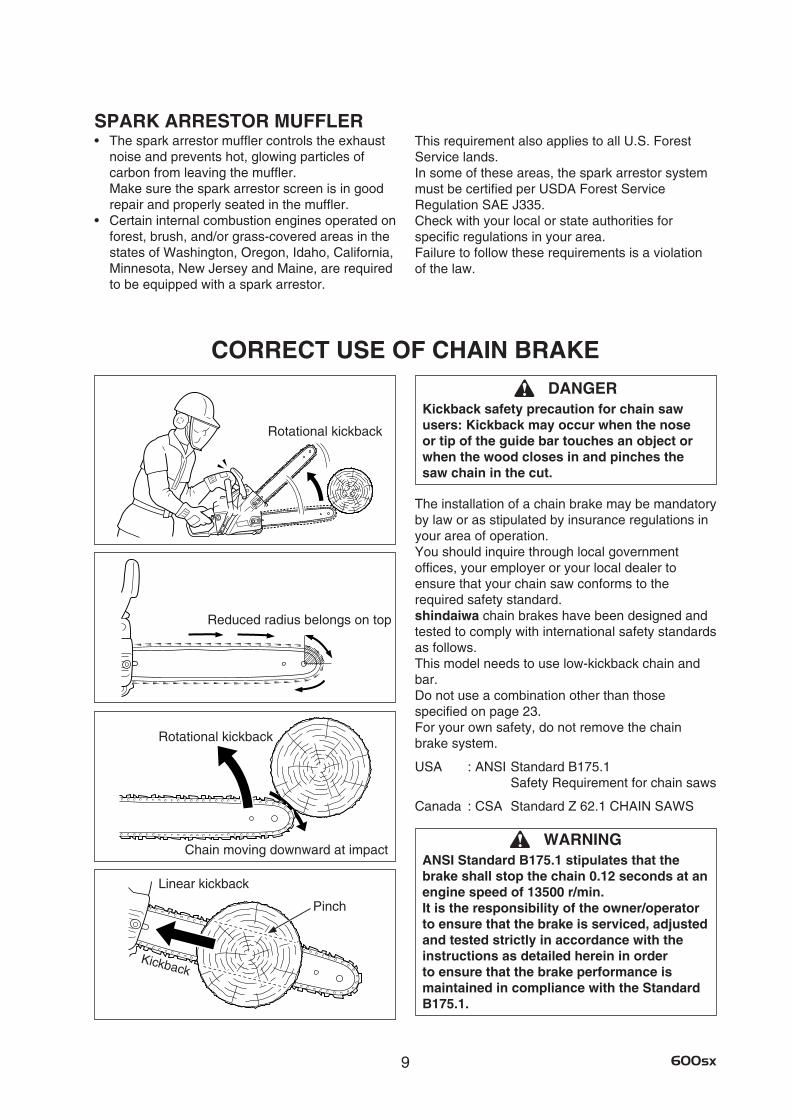
CORRECT USE OF CHAIN BRAKE
Linear kickback
Rotational kickback
Chain moving downward at impact
Rotational kickback
Reduced radius belongs on top
Pinch
Kickback
This requirement also applies to all U.S. Forest Service lands. In some of these areas, the spark arrestor system must be certified per USDA Forest Service Regulation SAE J335. Check with your local or state authorities for specific regulations in your area. Failure to follow these requirements is a violation of the law.
DANGERKickback safety precaution for chain saw users: Kickback may occur when the nose or tip of the guide bar touches an object or when the wood closes in and pinches the saw chain in the cut.
The installation of a chain brake may be mandatory by law or as stipulated by insurance regulations in your area of operation. You should inquire through local government offices, your employer or your local dealer to ensure that your chain saw conforms to the required safety standard. shindaiwa chain brakes have been designed and tested to comply with international safety standards as follows. This model needs to use low-kickback chain and bar. Do not use a combination other than those specified on page 23. For your own safety, do not remove the chain brake system.
USA : ANSI Standard B175.1 Safety Requirement for chain saws
Canada : CSA Standard Z 62.1 CHAIN SAWS
WARNINGANSI Standard B175.1 stipulates that the brake shall stop the chain 0.12 seconds at an engine speed of 13500 r/min. It is the responsibility of the owner/operator to ensure that the brake is serviced, adjusted and tested strictly in accordance with the instructions as detailed herein in order to ensure that the brake performance is maintained in compliance with the Standard B175.1.
10600sx
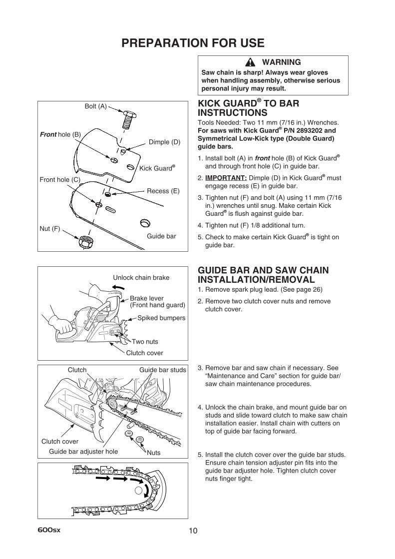
WARNINGSaw chain is sharp! Always wear gloves when handling assembly, otherwise serious personal injury may result.
KICK GUARD® TO BAR INSTRUCTIONSTools Needed: Two 11 mm (7/16 in.) Wrenches.For saws with Kick Guard® P/N 2893202 and Symmetrical Low-Kick type (Double Guard) guide bars.
1. Install bolt (A) in front hole (B) of Kick Guard® and through front hole (C) in guide bar.
2. IMPORTANT: Dimple (D) in Kick Guard® must engage recess (E) in guide bar.
3. Tighten nut (F) and bolt (A) using 11 mm (7/16 in.) wrenches until snug. Make certain Kick Guard® is flush against guide bar.
4. Tighten nut (F) 1/8 additional turn.
5. Check to make certain Kick Guard® is tight on guide bar.
GUIDE BAR AND SAW CHAIN INSTALLATION/REMOVAL1. Remove spark plug lead. (See page 26)
2. Remove two clutch cover nuts and remove clutch cover.
3. Remove bar and saw chain if necessary. See “Maintenance and Care” section for guide bar/saw chain maintenance procedures.
4. Unlock the chain brake, and mount guide bar on studs and slide toward clutch to make saw chain installation easier. Install chain with cutters on top of guide bar facing forward.
5. Install the clutch cover over the guide bar studs. Ensure chain tension adjuster pin fits into the guide bar adjuster hole. Tighten clutch cover nuts finger tight.
Guide bar adjuster hole
Clutch cover
Nuts
Clutch Guide bar studs
PREPARATION FOR USE
Bolt (A)
Dimple (D)
Recess (E)
Front hole (C)
Front hole (B)
Nut (F)Guide bar
Kick Guard®
Clutch cover
Brake lever(Front hand guard)
Two nuts
Unlock chain brake
Spiked bumpers
11 600sx
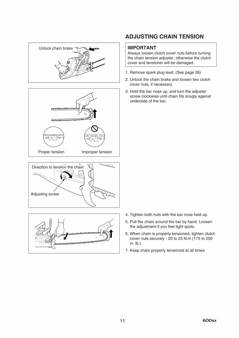
ADJUSTING CHAIN TENSION
IMPORTANTAlways loosen clutch cover nuts before turning the chain tension adjuster, otherwise the clutch cover and tensioner will be damaged.
1. Remove spark plug lead. (See page 26)
2. Unlock the chain brake and loosen two clutch cover nuts, if necessary.
3. Hold the bar nose up, and turn the adjuster screw clockwise until chain fits snugly against underside of the bar.
4. Tighten both nuts with the bar nose held up.
5. Pull the chain around the bar by hand. Loosen the adjustment if you feel tight spots.
6. When chain is properly tensioned, tighten clutch cover nuts securely - 20 to 23 N·m (175 to 200 in. lb.).
7. Keep chain properly tensioned at all times.
Adjusting screw
Proper tension Improper tension
Unlock chain brake
Direction to tension the chain
12600sx
WARNINGAlternative fuels, such as E-15 (15 % ethanol), E-85 (85 % ethanol) or any fuels not meeting shindaiwa requirements are not approved for use in shindaiwa gasoline engines. Use of alternative fuels may cause performance problems, loss of power, overheating, fuel vapor lock, and unintended machine operation, including, but not limited to, improper clutch engagement. Alternative fuels may also cause premature deterioration of fuel lines, gaskets, carburetors and other engine components.
IMPORTANT •shindaiwa Red Armor™ engine oil may
be mixed at 50 : 1 ratio for application in all shindaiwa engines sold in the past, regardless of ratio specified in those manuals.
•Useofunmixed,improperlymixed,orfuelolderthan 90 days, (stale fuel), may cause hard starting, poor performance, or severe engine damage and void the product warranty. Read and follow instructions in the Storage section of this manual.
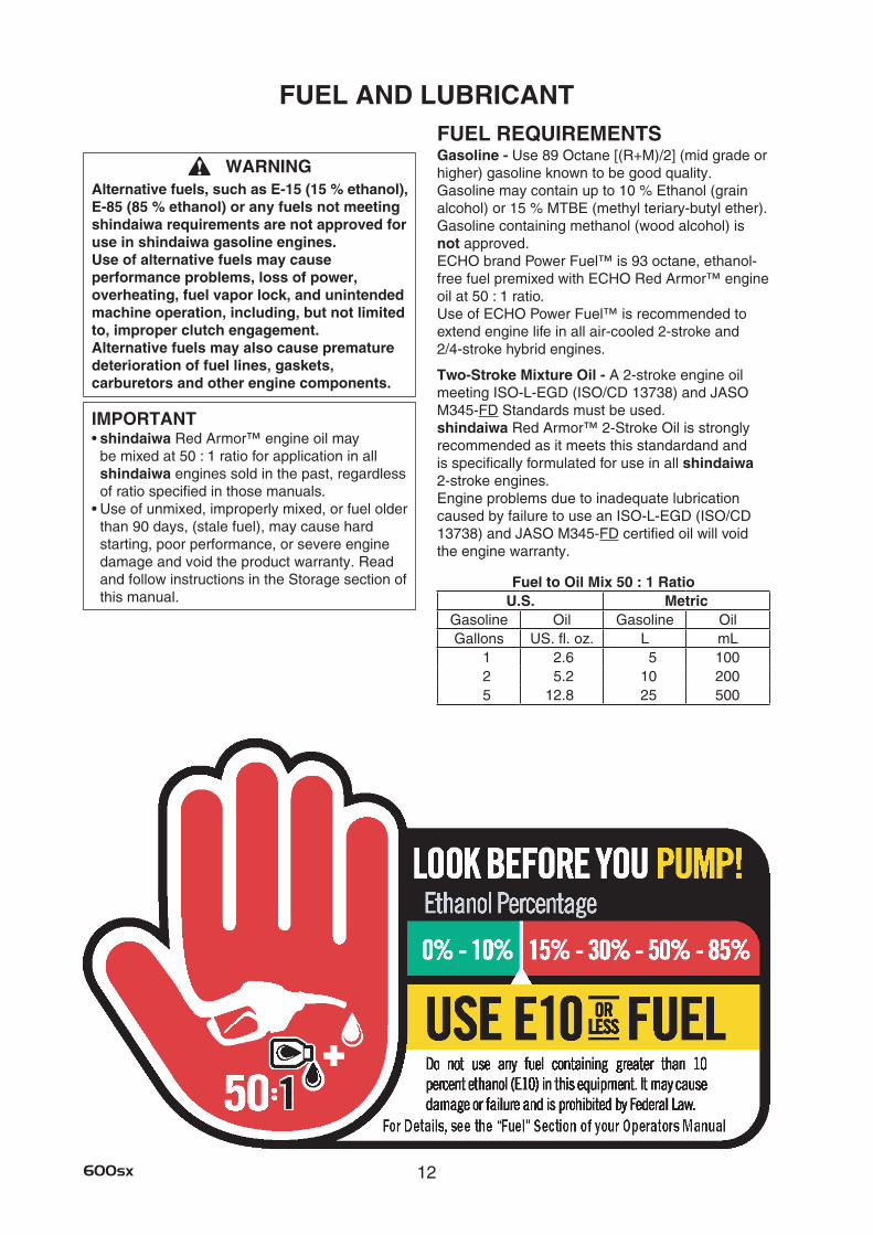
Fuel to Oil Mix 50 : 1 RatioU.S. Metric
Gasoline Oil Gasoline OilGallons US. fl. oz. L mL
1 2.6 5 1002 5.2 10 2005 12.8 25 500
FUEL AND LUBRICANTFUEL REQUIREMENTSGasoline - Use 89 Octane [(R+M)/2] (mid grade or higher) gasoline known to be good quality. Gasoline may contain up to 10 % Ethanol (grain alcohol) or 15 % MTBE (methyl teriary-butyl ether). Gasoline containing methanol (wood alcohol) is not approved. ECHO brand Power Fuel™ is 93 octane, ethanol-free fuel premixed with ECHO Red Armor™ engine oil at 50 : 1 ratio. Use of ECHO Power Fuel™ is recommended to extend engine life in all air-cooled 2-stroke and 2/4-stroke hybrid engines.
Two-Stroke Mixture Oil - A 2-stroke engine oil meeting ISO-L-EGD (ISO/CD 13738) and JASO M345-FD Standards must be used. shindaiwa Red Armor™ 2-Stroke Oil is strongly recommended as it meets this standardand and is specifically formulated for use in all shindaiwa 2-stroke engines. Engine problems due to inadequate lubrication caused by failure to use an ISO-L-EGD (ISO/CD 13738) and JASO M345-FD certified oil will void the engine warranty.
13 600sx
HANDLING FUELMixing Instructions - 1. Fill an approved fuel container with half of the
required amount of gasoline.
2. Add the proper amount of engine oil to gasoline.
3. Close container and shake to mix oil with gasoline.
4. Add remaining gasoline, close fuel container, and remix.
IMPORTANT •Spilledfuelisaleadingcauseofhydrocarbon
emissions. Some states may require the use of automatic fuel shut-off containers to reduce fuel spillage.
•Storedfuelages. Do not mix more fuel than you expect to use in thirty (30) days, ninety (90) days when a fuel stabilizer is added.
•Storedtwo-strokefuelmayseparate. Always shake fuel container thoroughly before each use.
After Use - Do not store a unit with fuel in its tank. Leaks can occur. Return unused fuel to an approved fuel storage container.
Storage - Fuel storage laws vary by locality. Contact your local government for the laws affecting your area. As a precaution, store fuel in an approved, airtight container. Store in a well-ventilated, unoccupied building, away from sparks and flames.
DANGERFuel is very flammable. Use extreme care when mixing, storing or handling, or serious personal injury may result. •Useanapprovedfuelcontainer.•Donotsmokenearfuel.•Donotallowflamesorsparksnearfuel.•Fueltanks/cansmaybeunderpressure.
Always loosen fuel caps slowly allowing pressure to equalize.
•Neverrefuelaunitwhentheengineishotor running!
•Donotfillfueltanksindoors. Alwaysfillfueltanksoutdoorsoverbareground.
•Donotoverfillfueltank. Wipe up spills immediately.
•Securelytightenfueltankcapandfuelcontainer after refueling.
•Inspectforfuelleakage. If fuel leakage is found, do not start or operate unit until leakage is repaired.
•Moveatleast3m(10feet)fromrefuelinglocation before starting the engine.
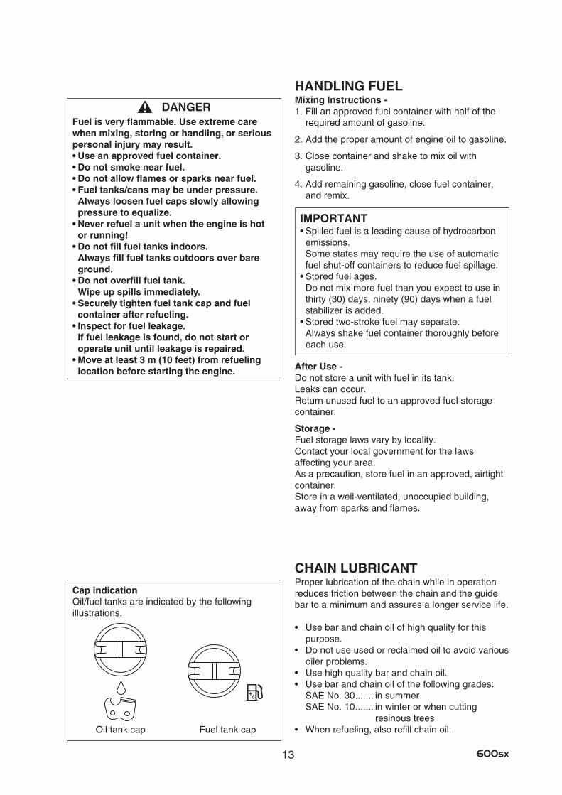
Oil tank cap
CHAIN LUBRICANTProper lubrication of the chain while in operation reduces friction between the chain and the guide bar to a minimum and assures a longer service life.
• Usebarandchainoilofhighqualityforthis purpose.
• Donotuseusedorreclaimedoiltoavoidvariousoiler problems.
• Usehighqualitybarandchainoil.• Usebarandchainoilofthefollowinggrades:
SAE No. 30 ....... in summerSAE No. 10 ....... in winter or when cutting
resinous trees• Whenrefueling,alsorefillchainoil.Fuel tank cap
Cap indicationOil/fuel tanks are indicated by the following illustrations.

14600sx
EMISSION DATAEMISSION CONTROL(EXHAUST and EVAPORATIVE) EPA 2010 and later and/or C.A.R.B. TIER IIIThe emission control system for the engine is EM (Engine Modification) and, if the second to last character of the Engine Family on the Emission Control Information label (sample below) is “C”, “K”, or “T”, the emission control system is EM and TWC (3-way Catalyst). The fuel tank/fuel line emission control system is EVAP (Evaporative Emissions). Evaporative emissions for California models are only applicable to fuel tanks.
Product Emission Durability (Emission Compliance Period)The 50 or 300 hours emission compliance period is the time span selected by the manufacturer certifying the engine emissions output meets applicable emissions regulations, provided that approved maintenance procedures are followed as listed in the Maintenance Section of this manual.
EMISSION CONTROL INFORMATIONENGINE FAMILY: #EHXS.0605EC DISPLACEMENT: 59.8 cc EMISSION COMPLIANCE PERIOD: 300 Hours THIS ENGINE MEETS U.S. EPA EXH/EVP EMISSION REGULATIONS FOR MODEL YEAR * * * * REFER TO OWNER’S MANUAL FOR MAINTENANCE SPECIFICATIONS AND ADJUSTMENTS.
* * * ? ? ? ?
15 600sx
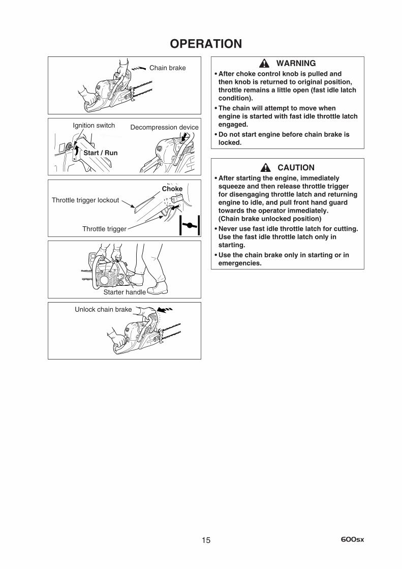
WARNING•Afterchokecontrolknobispulledand
then knob is returned to original position, throttle remains a little open (fast idle latch condition).
•Thechainwillattempttomovewhenengine is started with fast idle throttle latch engaged.
•Donotstartenginebeforechainbrakeislocked.
CAUTION•Afterstartingtheengine,immediately
squeeze and then release throttle trigger for disengaging throttle latch and returning engine to idle, and pull front hand guard towards the operator immediately. (Chain brake unlocked position)
•Neverusefastidlethrottlelatchforcutting. Use the fast idle throttle latch only in starting.
•Usethechainbrakeonlyinstartingorinemergencies.
OPERATION
Start / Run
Ignition switch
Chain brake
Starter handle
Unlock chain brake
Throttle trigger
Choke
Throttle trigger lockout
Decompression device
16600sx
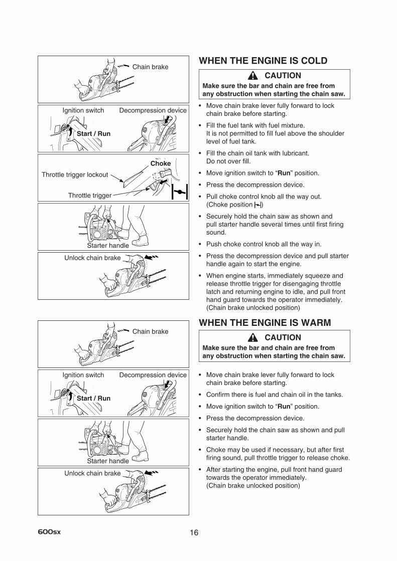
WHEN THE ENGINE IS COLD
CAUTIONMake sure the bar and chain are free from any obstruction when starting the chain saw.
• Movechainbrakeleverfullyforwardtolockchain brake before starting.
• Fillthefueltankwithfuelmixture. It is not permitted to fill fuel above the shoulder level of fuel tank.
• Fillthechainoiltankwithlubricant. Do not over fill.
• Moveignitionswitchto“Run” position.
• Pressthedecompressiondevice.
• Pullchokecontrolknoballthewayout. (Choke position )
• Securelyholdthechainsawasshownandpull starter handle several times until first firing sound.
• Pushchokecontrolknoballthewayin.
• Pressthedecompressiondeviceandpullstarterhandle again to start the engine.
• Whenenginestarts,immediatelysqueezeandrelease throttle trigger for disengaging throttle latch and returning engine to idle, and pull front hand guard towards the operator immediately. (Chain brake unlocked position)
WHEN THE ENGINE IS WARM
CAUTIONMake sure the bar and chain are free from any obstruction when starting the chain saw.
• Movechainbrakeleverfullyforwardtolockchain brake before starting.
• Confirmthereisfuelandchainoilinthetanks.
• Moveignitionswitchto“Run” position.
• Pressthedecompressiondevice.
• Securelyholdthechainsawasshownandpullstarter handle.
• Chokemaybeusedifnecessary,butafterfirstfiring sound, pull throttle trigger to release choke.
• Afterstartingtheengine,pullfronthandguardtowards the operator immediately. (Chain brake unlocked position)
Chain brake
Chain brake
Start / Run
Ignition switch Decompression device
Start / Run
Ignition switch Decompression device
Starter handle
Starter handle
Throttle trigger
Choke
Throttle trigger lockout
Unlock chain brake
Unlock chain brake
17 600sx
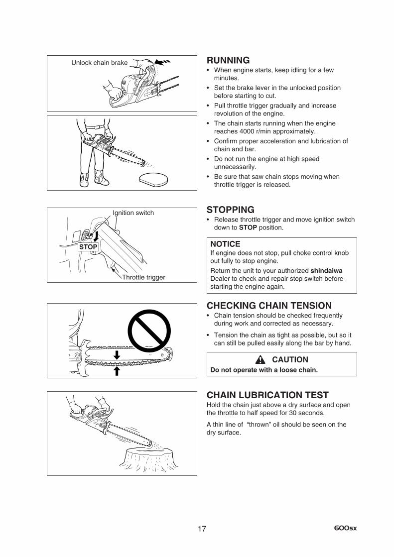
RUNNING• Whenenginestarts,keepidlingforafew
minutes.
• Setthebrakeleverintheunlockedposition before starting to cut.
• Pullthrottletriggergraduallyandincrease revolution of the engine.
• Thechainstartsrunningwhentheenginereaches 4000 r/min approximately.
• Confirmproperaccelerationandlubricationofchain and bar.
• Donotruntheengineathighspeed unnecessarily.
• Besurethatsawchainstopsmovingwhen throttle trigger is released.
STOPPING• Releasethrottletriggerandmoveignitionswitch
down to STOP position.
NOTICEIf engine does not stop, pull choke control knob out fully to stop engine.
Return the unit to your authorized shindaiwa Dealer to check and repair stop switch before starting the engine again.
CHECKING CHAIN TENSION• Chaintensionshouldbecheckedfrequently
during work and corrected as necessary.
• Tensionthechainastightaspossible,butsoitcan still be pulled easily along the bar by hand.
CAUTIONDo not operate with a loose chain.
CHAIN LUBRICATION TESTHold the chain just above a dry surface and open the throttle to half speed for 30 seconds.
A thin line of “thrown” oil should be seen on the dry surface.
Ignition switch
Throttle trigger
Unlock chain brake
STOP
18600sx
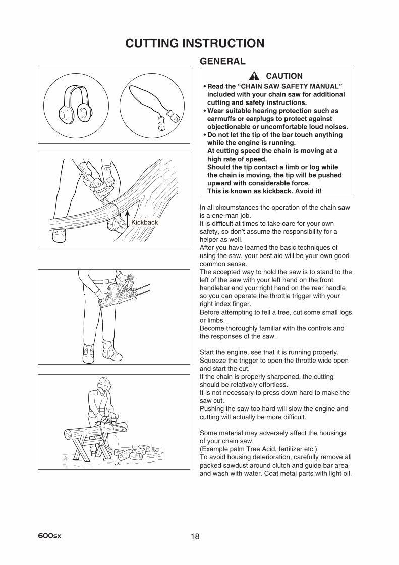
CUTTING INSTRUCTIONGENERAL
CAUTION•Readthe“CHAINSAWSAFETYMANUAL”
included with your chain saw for additional cutting and safety instructions.
•Wearsuitablehearingprotectionsuchasearmuffs or earplugs to protect against objectionable or uncomfortable loud noises.
•Donotletthetipofthebartouchanythingwhile the engine is running. At cutting speed the chain is moving at a high rate of speed. Should the tip contact a limb or log while the chain is moving, the tip will be pushed upward with considerable force. This is known as kickback. Avoid it!
In all circumstances the operation of the chain saw is a one-man job. It is difficult at times to take care for your own safety, so don’t assume the responsibility for a helper as well. After you have learned the basic techniques of using the saw, your best aid will be your own good common sense. The accepted way to hold the saw is to stand to the left of the saw with your left hand on the front handlebar and your right hand on the rear handle so you can operate the throttle trigger with your right index finger. Before attempting to fell a tree, cut some small logs or limbs. Become thoroughly familiar with the controls and the responses of the saw.
Start the engine, see that it is running properly. Squeeze the trigger to open the throttle wide open and start the cut. If the chain is properly sharpened, the cutting should be relatively effortless. It is not necessary to press down hard to make the saw cut. Pushing the saw too hard will slow the engine and cutting will actually be more difficult.
Some material may adversely affect the housings of your chain saw. (Example palm Tree Acid, fertilizer etc.) To avoid housing deterioration, carefully remove all packed sawdust around clutch and guide bar area and wash with water. Coat metal parts with light oil.
Kickback
19 600sx
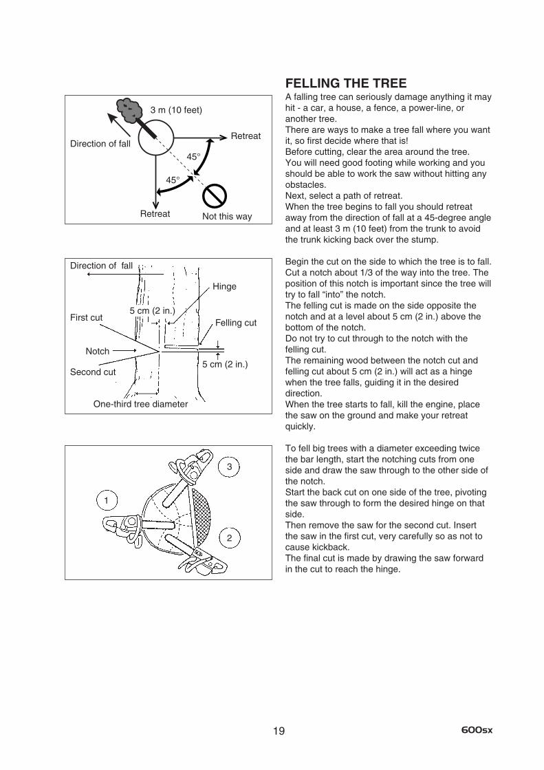
FELLING THE TREEA falling tree can seriously damage anything it may hit - a car, a house, a fence, a power-line, or another tree. There are ways to make a tree fall where you want it, so first decide where that is! Before cutting, clear the area around the tree. You will need good footing while working and you should be able to work the saw without hitting any obstacles. Next, select a path of retreat. When the tree begins to fall you should retreat away from the direction of fall at a 45-degree angle and at least 3 m (10 feet) from the trunk to avoid the trunk kicking back over the stump.
Begin the cut on the side to which the tree is to fall. Cut a notch about 1/3 of the way into the tree. The position of this notch is important since the tree will try to fall “into” the notch. The felling cut is made on the side opposite the notch and at a level about 5 cm (2 in.) above the bottom of the notch. Do not try to cut through to the notch with the felling cut. The remaining wood between the notch cut and felling cut about 5 cm (2 in.) will act as a hinge when the tree falls, guiding it in the desired direction. When the tree starts to fall, kill the engine, place the saw on the ground and make your retreat quickly.
To fell big trees with a diameter exceeding twice the bar length, start the notching cuts from one side and draw the saw through to the other side of the notch. Start the back cut on one side of the tree, pivoting the saw through to form the desired hinge on that side. Then remove the saw for the second cut. Insert the saw in the first cut, very carefully so as not to cause kickback. The final cut is made by drawing the saw forward in the cut to reach the hinge.
1
2
3
Felling cut
Hinge
Direction of fall
First cut
Notch
Second cut
One-third tree diameter
Direction of fall
5 cm (2 in.)
5 cm (2 in.)
45°
45°
Not this way
Retreat
Retreat
3 m (10 feet)
20600sx
LIMBINGLimbing a fallen tree is much the same as bucking.
Never stand on the tree that you are limbing.
When limbing, caution is the word. Be careful of the tip touching other limbs. Always use both hands.
Don’t cut with the saw overhead or aligned vertically with your body. If the saw should kick-back, you may not have enough control to prevent possible injury.
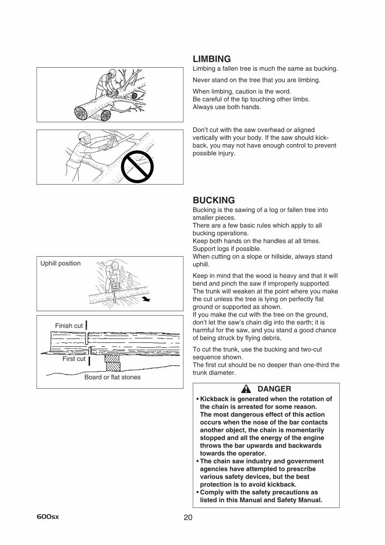
BUCKINGBucking is the sawing of a log or fallen tree into smaller pieces. There are a few basic rules which apply to all bucking operations. Keep both hands on the handles at all times. Support logs if possible. When cutting on a slope or hillside, always stand uphill.
Keep in mind that the wood is heavy and that it will bend and pinch the saw if improperly supported. The trunk will weaken at the point where you make the cut unless the tree is lying on perfectly flat ground or supported as shown. If you make the cut with the tree on the ground, don’t let the saw’s chain dig into the earth; it is harmful for the saw, and you stand a good chance of being struck by flying debris.
To cut the trunk, use the bucking and two-cut sequence shown. The first cut should be no deeper than one-third the trunk diameter.
DANGER•Kickbackisgeneratedwhentherotationof
the chain is arrested for some reason. The most dangerous effect of this action occurs when the nose of the bar contacts another object, the chain is momentarily stopped and all the energy of the engine throws the bar upwards and backwards towards the operator.
•Thechainsawindustryandgovernmentagencies have attempted to prescribe various safety devices, but the best protection is to avoid kickback.
•Complywiththesafetyprecautionsaslisted in this Manual and Safety Manual.
Uphill position
Finish cut
First cut
Board or flat stones
21 600sx
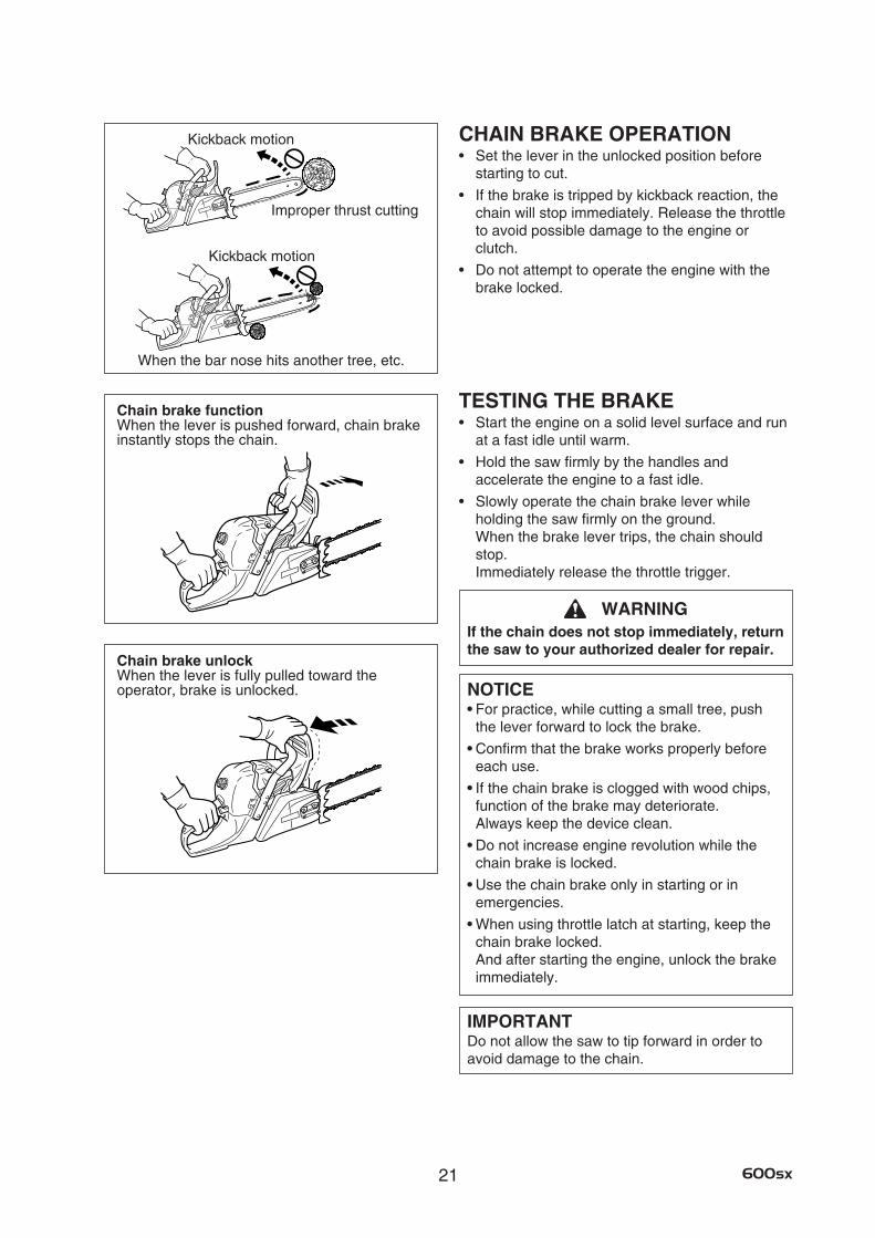
Chain brake functionWhen the lever is pushed forward, chain brake instantly stops the chain.
Chain brake unlockWhen the lever is fully pulled toward the operator, brake is unlocked.
When the bar nose hits another tree, etc.
Improper thrust cutting
CHAIN BRAKE OPERATION• Settheleverintheunlockedpositionbefore
starting to cut.
• Ifthebrakeistrippedbykickbackreaction,thechain will stop immediately. Release the throttle to avoid possible damage to the engine or clutch.
• Donotattempttooperatetheenginewiththebrake locked.
TESTING THE BRAKE• Starttheengineonasolidlevelsurfaceandrun
at a fast idle until warm.
• Holdthesawfirmlybythehandlesand accelerate the engine to a fast idle.
• Slowlyoperatethechainbrakeleverwhile holding the saw firmly on the ground. When the brake lever trips, the chain should stop. Immediately release the throttle trigger.
WARNINGIf the chain does not stop immediately, return the saw to your authorized dealer for repair.
NOTICE•For practice, while cutting a small tree, push
the lever forward to lock the brake.
•Confirm that the brake works properly before each use.
•If the chain brake is clogged with wood chips, function of the brake may deteriorate. Always keep the device clean.
•Do not increase engine revolution while the chain brake is locked.
•Use the chain brake only in starting or in emergencies.
•When using throttle latch at starting, keep the chain brake locked. And after starting the engine, unlock the brake immediately.
IMPORTANTDo not allow the saw to tip forward in order to avoid damage to the chain.
Kickback motion
Kickback motion
22600sx
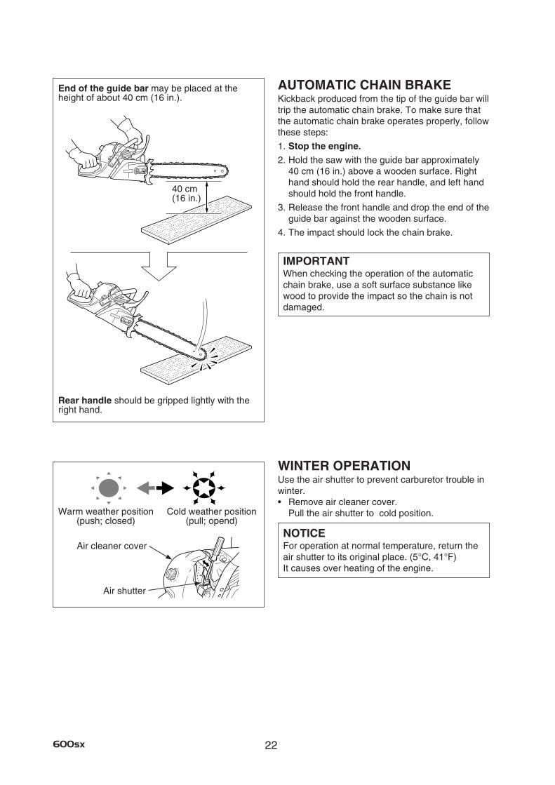
End of the guide bar may be placed at the height of about 40 cm (16 in.).
40 cm(16 in.)
AUTOMATIC CHAIN BRAKEKickback produced from the tip of the guide bar will trip the automatic chain brake. To make sure that the automatic chain brake operates properly, follow these steps:
1. Stop the engine. 2. Hold the saw with the guide bar approximately
40 cm (16 in.) above a wooden surface. Right hand should hold the rear handle, and left hand should hold the front handle.
3. Release the front handle and drop the end of the guide bar against the wooden surface.
4. The impact should lock the chain brake.
IMPORTANTWhen checking the operation of the automatic chain brake, use a soft surface substance like wood to provide the impact so the chain is not damaged.
WINTER OPERATIONUse the air shutter to prevent carburetor trouble in winter.• Removeaircleanercover.
Pull the air shutter to cold position.
NOTICEFor operation at normal temperature, return the air shutter to its original place. (5°C, 41°F) It causes over heating of the engine.
Rear handle should be gripped lightly with the right hand.
Air cleaner cover
Air shutter
Warm weather position (push; closed)
Cold weather position (pull; opend)
23 600sx
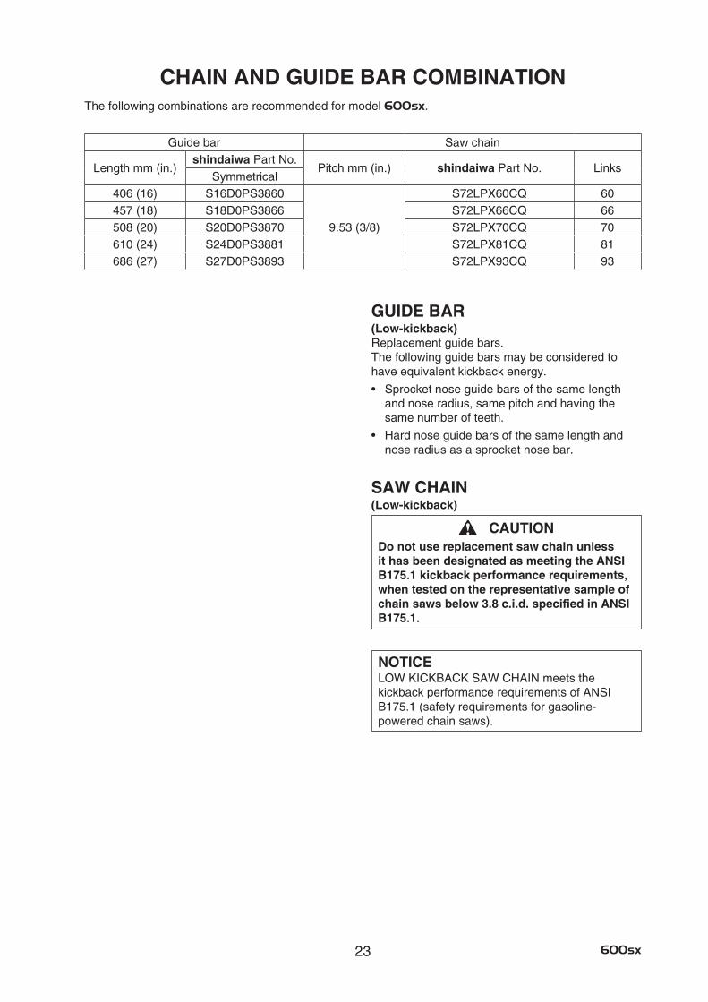
CHAIN AND GUIDE BAR COMBINATIONThe following combinations are recommended for model 600sx.
GUIDE BAR(Low-kickback)Replacement guide bars. The following guide bars may be considered to have equivalent kickback energy.
• Sprocketnoseguidebarsofthesamelengthand nose radius, same pitch and having the same number of teeth.
• Hardnoseguidebarsofthesamelengthandnose radius as a sprocket nose bar.
SAW CHAIN(Low-kickback)
CAUTIONDo not use replacement saw chain unless it has been designated as meeting the ANSI B175.1 kickback performance requirements, when tested on the representative sample of chainsawsbelow3.8c.i.d.specifiedinANSIB175.1.
NOTICELOW KICKBACK SAW CHAIN meets the kickback performance requirements of ANSI B175.1 (safety requirements for gasoline-powered chain saws).
Guide bar Saw chain
Length mm (in.)shindaiwa Part No.
Pitch mm (in.) shindaiwa Part No. LinksSymmetrical
406 (16) S16D0PS3860
9.53 (3/8)
S72LPX60CQ 60457 (18) S18D0PS3866 S72LPX66CQ 66508 (20) S20D0PS3870 S72LPX70CQ 70610 (24) S24D0PS3881 S72LPX81CQ 81686 (27) S27D0PS3893 S72LPX93CQ 93
24600sx
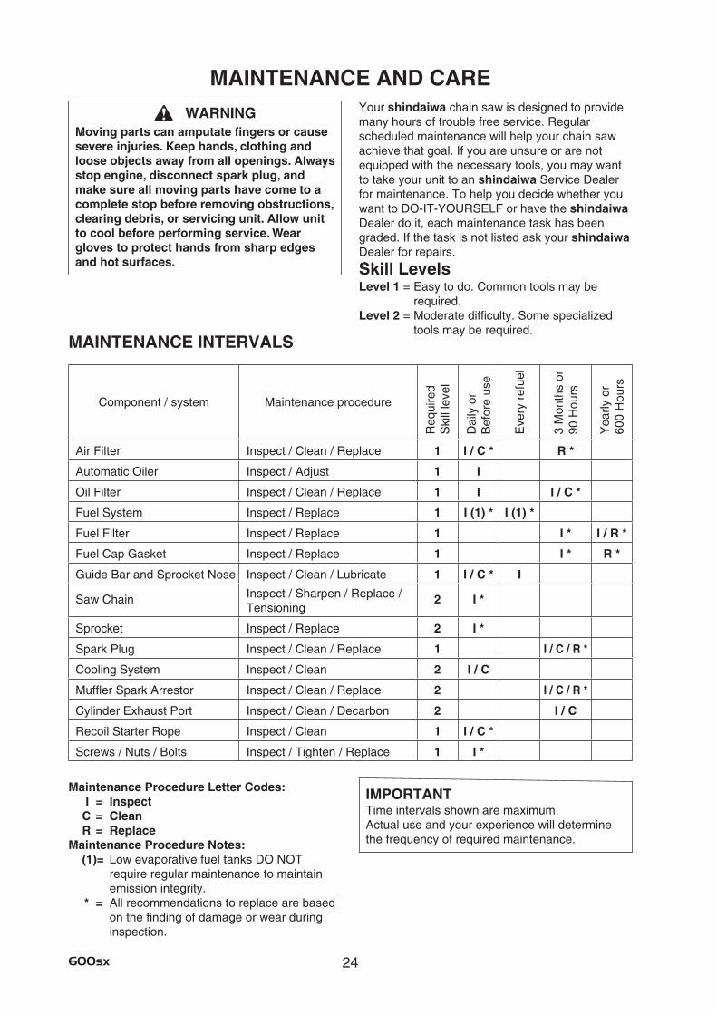
MAINTENANCE AND CARE
IMPORTANTTime intervals shown are maximum. Actual use and your experience will determine the frequency of required maintenance.
WARNINGMovingpartscanamputatefingersorcausesevere injuries. Keep hands, clothing and loose objects away from all openings. Always stop engine, disconnect spark plug, and make sure all moving parts have come to a complete stop before removing obstructions, clearing debris, or servicing unit. Allow unit to cool before performing service. Wear gloves to protect hands from sharp edges and hot surfaces.
Your shindaiwa chain saw is designed to provide many hours of trouble free service. Regular scheduled maintenance will help your chain saw achieve that goal. If you are unsure or are not equipped with the necessary tools, you may want to take your unit to an shindaiwa Service Dealer for maintenance. To help you decide whether you want to DO-IT-YOURSELF or have the shindaiwa Dealer do it, each maintenance task has been graded. If the task is not listed ask your shindaiwa Dealer for repairs.
Skill LevelsLevel 1 = Easy to do. Common tools may be
required. Level 2 = Moderate difficulty. Some specialized
tools may be required. MAINTENANCE INTERVALS
Maintenance Procedure Letter Codes: I = Inspect C = Clean R = Replace
Maintenance Procedure Notes:(1)= Low evaporative fuel tanks DO NOT
require regular maintenance to maintain emission integrity.
* = All recommendations to replace are based on the finding of damage or wear during inspection.
Component / system Maintenance procedure
Req
uire
d S
kill
leve
l
Dai
ly o
r B
efor
e us
e
Eve
ry r
efue
l
3 M
onth
s or
90
Hou
rs
Yea
rly o
r 60
0 H
ours
Air Filter Inspect / Clean / Replace 1 I / C * R *
Automatic Oiler Inspect / Adjust 1 I
Oil Filter Inspect / Clean / Replace 1 I I / C *
Fuel System Inspect / Replace 1 I (1) * I (1) *
Fuel Filter Inspect / Replace 1 I * I / R *
Fuel Cap Gasket Inspect / Replace 1 I * R *
Guide Bar and Sprocket Nose Inspect / Clean / Lubricate 1 I / C * I
Saw Chain Inspect / Sharpen / Replace / Tensioning
2 I *
Sprocket Inspect / Replace 2 I *
Spark Plug Inspect / Clean / Replace 1 I / C / R *
Cooling System Inspect / Clean 2 I / C
Muffler Spark Arrestor Inspect / Clean / Replace 2 I / C / R *
Cylinder Exhaust Port Inspect / Clean / Decarbon 2 I / C
Recoil Starter Rope Inspect / Clean 1 I / C *
Screws / Nuts / Bolts Inspect / Tighten / Replace 1 I *
25 600sx
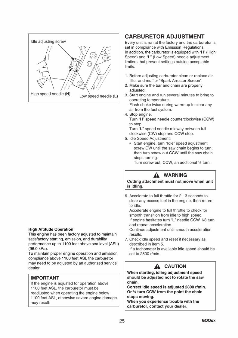
CARBURETOR ADJUSTMENTEvery unit is run at the factory and the carburetor is set in compliance with Emission Regulations. In addition, the carburetor is equipped with “H” (High Speed) and “L” (Low Speed) needle adjustment limiters that prevent settings outside acceptable limits.
1. Before adjusting carburetor clean or replace air filter and muffler “Spark Arrestor Screen”.
2. Make sure the bar and chain are properly adjusted.
3. Start engine and run several minutes to bring to operating temperature. Flash choke twice during warm-up to clear any air from the fuel system.
4. Stop engine. Turn “H” speed needle counterclockwise (CCW) to stop. Turn “L” speed needle midway between full clockwise (CW) stop and CCW stop.
5. Idle Speed Adjustment: • Startengine,turn“Idle”speedadjustment
screw CW until the saw chain begins to turn, then turn screw out CCW until the saw chain stops turning. Turn screw out, CCW, an additional ¼ turn.
WARNINGCutting attachment must not move when unit is idling.
6. Accelerate to full throttle for 2 - 3 seconds to clear any excess fuel in the engine, then return to idle. Accelerate engine to full throttle to check for smooth transition from idle to high speed. If engine hesitates turn “L” needle CCW 1/8 turn and repeat acceleration. Continue adjustment until smooth acceleration results.
7. Check idle speed and reset if necessary as described in item 5. If a tachometer is available idle speed should be set to 2800 r/min.
CAUTIONWhen starting, idling adjustment speed should be adjusted not to rotate the saw chain. Correct idle speed is adjusted 2800 r/min. Or ¼ turn CCW from the point the chain stops moving. When you experience trouble with the carburetor, contact your dealer.
Idle adjusting screw
Low speed needle (L)High speed needle (H)
High Altitude OperationThis engine has been factory adjusted to maintain satisfactory starting, emission, and durability performance up to 1100 feet above sea level (ASL) (96.0 kPa). To maintain proper engine operation and emission compliance above 1100 feet ASL the carburetor may need to be adjusted by an authorized service dealer.
IMPORTANTIf the engine is adjusted for operation above 1100 feet ASL, the carburetor must be readjusted when operating the engine below 1100 feet ASL, otherwise severe engine damage may result.
26600sx
Oil filter
Fuel filterOil tank cap Fuel tank cap
0.65 mm (0.026 in.)
Cleaner cover knob
Air filterAir cleaner cover
AIR FILTER• Checkbeforeeveryuse.• Closechoke( ). • Turncleanercoverknobcounterclockwiseby
hand and remove air cleaner cover and air filter.• Brushoffdustlightly,orcleanwithcompressed
air, or replace the air filter. • Reinstallairfilterandcover.
CHECK FUEL SYSTEM• Checkbeforeeveryuse.• Afterrefueling,makesurefueldoesnotleak
from around fuel pipe, fuel grommet or fuel tank cap.
• Incaseoffuelleakagethereisadangeroffire.Stop using the machine immediately and request your dealer to inspect or replace.
SPARK PLUG• Checkperiodically.• Thestandardsparkgapis0.65mm
(0.026 in.). • Correctthesparkgapifitiswiderornarrower
than the standard gap. • Fasteningtorque: 15to17N·m
(130 to 145 in. lb.).
FUEL FILTER• Checkperiodically.• Donotallowdusttoenterfueltank.• Acloggedfilterwillcausedifficultyinstarting
engine or abnormalities in engine performance. • Pullthefuelfilteroutthroughfuelinletportwith
a piece of steel wire or the like. • Whenthefilterisdirty,replaceit.• Whentheinsideofthefueltankisdirty,rinsing
the tank out with gasoline can clean it.
OIL FILTER• Checkperiodically.• Donotallowdusttoenterintooiltank.• Acloggedoilfilterwillaffectthenormal
lubricating system. • Pullitoutthroughoilfillingholewithapieceof
steel wire or the like. • Ifthefilterisdirty,washitingasolineorreplace
it. • Whentheinsideofthetankgetsdirty,rinsing
the tank out with gasoline can clean it.
Cylinder coverSpark plug
27 600sx
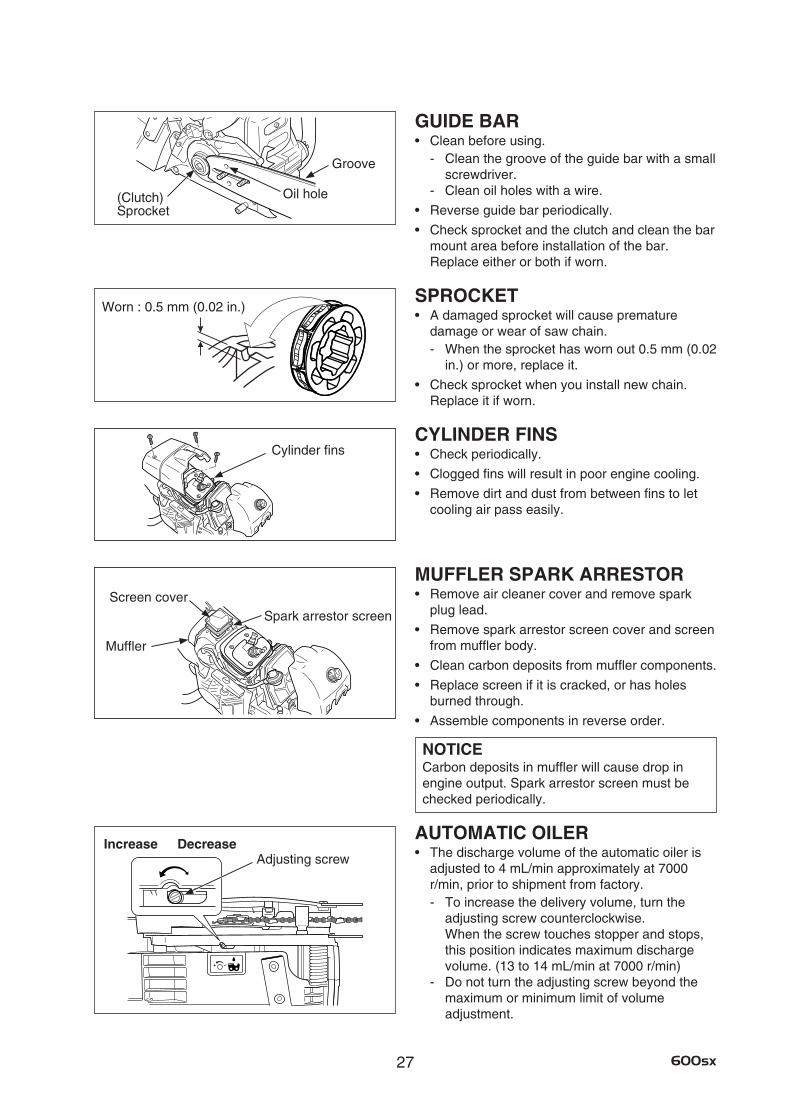
GUIDE BAR• Cleanbeforeusing.
- Clean the groove of the guide bar with a small screwdriver.
- Clean oil holes with a wire.
• Reverseguidebarperiodically.
• Checksprocketandtheclutchandcleanthebarmount area before installation of the bar. Replace either or both if worn.
SPROCKET• Adamagedsprocketwillcausepremature
damage or wear of saw chain. - When the sprocket has worn out 0.5 mm (0.02
in.) or more, replace it.
• Checksprocketwhenyouinstallnewchain. Replace it if worn.
CYLINDER FINS• Checkperiodically.
• Cloggedfinswillresultinpoorenginecooling.
• Removedirtanddustfrombetweenfinstoletcooling air pass easily.
MUFFLER SPARK ARRESTOR• Removeaircleanercoverandremovespark
plug lead.
• Removesparkarrestorscreencoverandscreenfrom muffler body.
• Cleancarbondepositsfrommufflercomponents.
• Replacescreenifitiscracked,orhasholesburned through.
• Assemblecomponentsinreverseorder.
NOTICECarbon deposits in muffler will cause drop in engine output. Spark arrestor screen must be checked periodically.
AUTOMATIC OILER• Thedischargevolumeoftheautomaticoileris
adjusted to 4 mL/min approximately at 7000 r/min, prior to shipment from factory. - To increase the delivery volume, turn the
adjusting screw counterclockwise. When the screw touches stopper and stops, this position indicates maximum discharge volume. (13 to 14 mL/min at 7000 r/min)
- Do not turn the adjusting screw beyond the maximum or minimum limit of volume adjustment.
Worn : 0.5 mm (0.02 in.)
Groove
Oil hole
Cylinder fins
Spark arrestor screen
Muffler
Screen cover
(Clutch) Sprocket
DecreaseIncreaseAdjusting screw
28600sx
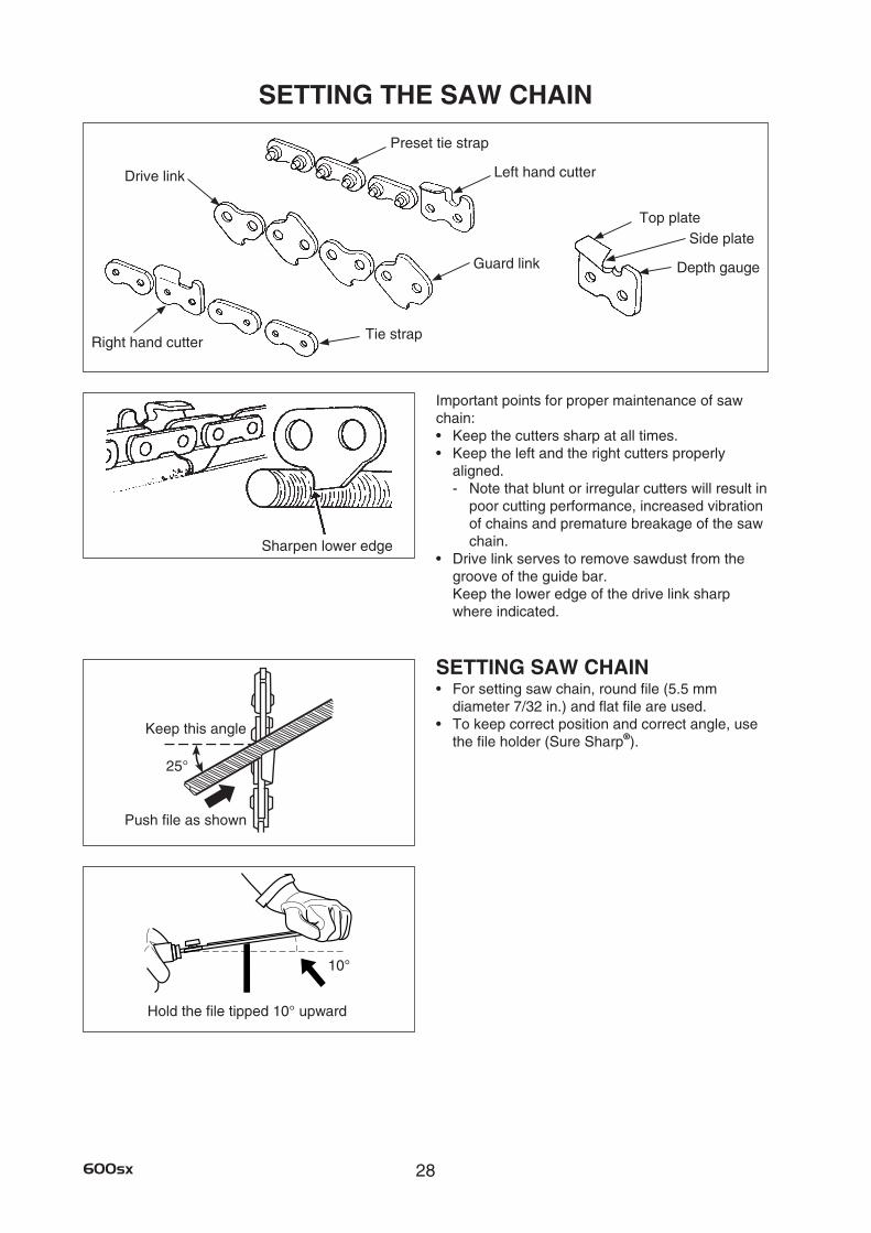
SETTING THE SAW CHAIN
Sharpen lower edge
Drive link
Tie strapRight hand cutter
Preset tie strap
Left hand cutter
Guard link
Top plateSide plate
Depth gauge
Hold the file tipped 10° upward
10°
Important points for proper maintenance of saw chain: • Keepthecutterssharpatalltimes.• Keeptheleftandtherightcuttersproperly
aligned. - Note that blunt or irregular cutters will result in
poor cutting performance, increased vibration of chains and premature breakage of the saw chain.
• Drivelinkservestoremovesawdustfromthegroove of the guide bar. Keep the lower edge of the drive link sharp where indicated.
SETTING SAW CHAIN• Forsettingsawchain,roundfile(5.5mm
diameter 7/32 in.) and flat file are used. • Tokeepcorrectpositionandcorrectangle,use
the file holder (Sure Sharp®).
25°
Push file as shown
Keep this angle
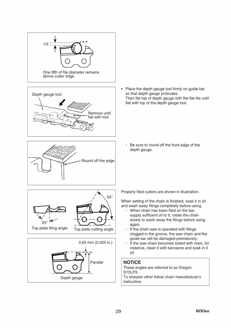
29 600sx
• Placethedepthgaugetoolfirmlyonguidebarso that depth gauge protrudes. Then file top of depth gauge with the flat file until flat with top of the depth gauge tool.
- Be sure to round off the front edge of the depth gauge.
Properly filed cutters are shown in illustration.
When setting of the chain is finished, soak it in oil and wash away filings completely before using.
- When chain has been filed on the bar, supply sufficient oil to it, rotate the chain slowly to wash away the filings before using again.
- If the chain saw is operated with filings clogged in the groove, the saw chain and the guide bar will be damaged prematurely.
- If the saw chain becomes soiled with resin, for instance, clean it with kerosene and soak in it oil.
NOTICEThese angles are referred to as Oregon S72LPX. To sharpen other follow chain manufacturer’s instruction.
Remove until flat with tool
Depth gauge tool
Round off the edge
1/5
One fifth of file diameter remains above cutter edge
Top plate filing angle
55°
25°
Parallel
0.65 mm (0.025 in.)
Top plate cutting angle
Depth gauge
30600sx
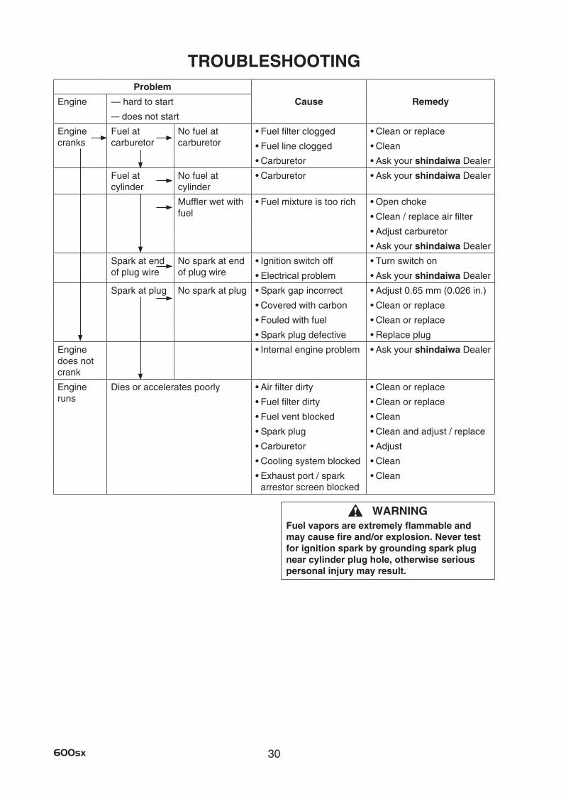
TROUBLESHOOTING
WARNINGFuel vapors are extremely flammable and maycausefireand/orexplosion.Nevertestfor ignition spark by grounding spark plug near cylinder plug hole, otherwise serious personal injury may result.
Problem
Engine — hard to start Cause Remedy
— does not start
Engine cranks
Fuel at carburetor
No fuel at carburetor
•Fuelfilterclogged •Cleanorreplace
•Fuellineclogged •Clean
•Carburetor •Askyourshindaiwa Dealer
Fuel at cylinder
No fuel at cylinder
•Carburetor •Askyourshindaiwa Dealer
Muffler wet with fuel
•Fuelmixtureistoorich •Openchoke
•Clean/replaceairfilter
•Adjustcarburetor
•Askyourshindaiwa Dealer
Spark at end of plug wire
No spark at end of plug wire
•Ignitionswitchoff •Turnswitchon
•Electricalproblem •Askyourshindaiwa Dealer
Spark at plug No spark at plug •Sparkgapincorrect •Adjust0.65mm(0.026in.)
•Coveredwithcarbon •Cleanorreplace
•Fouledwithfuel •Cleanorreplace
•Sparkplugdefective •Replaceplug
Engine does not crank
•Internalengineproblem •Askyourshindaiwa Dealer
Engine runs
Dies or accelerates poorly •Airfilterdirty •Cleanorreplace
•Fuelfilterdirty •Cleanorreplace
•Fuelventblocked •Clean
•Sparkplug •Cleanandadjust/replace
•Carburetor •Adjust
•Coolingsystemblocked •Clean
•Exhaustport/spark arrestor screen blocked
•Clean
31 600sx
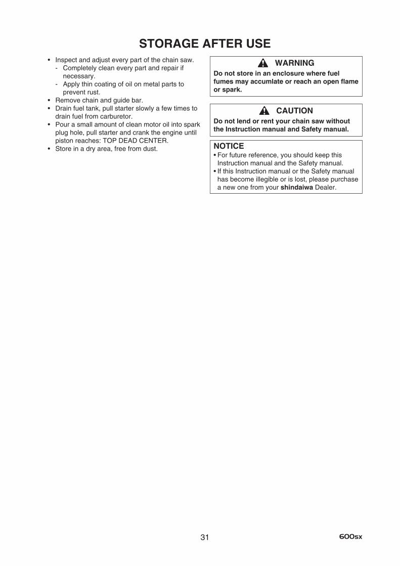
STORAGE AFTER USE• Inspectandadjusteverypartofthechainsaw.
- Completely clean every part and repair if necessary.
- Apply thin coating of oil on metal parts to prevent rust.
• Removechainandguidebar.• Drainfueltank,pullstarterslowlyafewtimesto
drain fuel from carburetor. • Pourasmallamountofcleanmotoroilintospark
plug hole, pull starter and crank the engine until piston reaches: TOP DEAD CENTER.
• Storeinadryarea,freefromdust.
WARNINGDo not store in an enclosure where fuel fumes may accumlate or reach an open flame or spark.
CAUTIONDo not lend or rent your chain saw without the Instruction manual and Safety manual.
NOTICE•Forfuturereference,youshouldkeepthis
Instruction manual and the Safety manual. •IfthisInstructionmanualortheSafetymanual
has become illegible or is lost, please purchase a new one from your shindaiwa Dealer.
32600sx
* Technical data subject to change without notice.
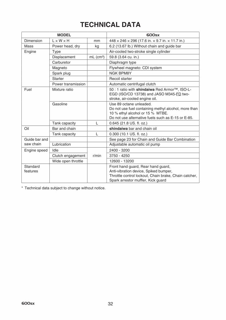
TECHNICAL DATAMODEL 600sx
Dimension L × W × H mm 448 × 246 × 296 (17.6 in. × 9.7 in. × 11.7 in.)Mass Power head, dry kg 6.2 (13.67 lb.) Without chain and guide barEngine Type Air-cooled two-stroke single cylinder
Displacement mL (cm³) 59.8 (3.64 cu. in.)Carburetor Diaphragm typeMagneto Flywheel magneto: CDI systemSpark plug NGK BPM8YStarter Recoil starterPower transmission Automatic centrifugal clutch
Fuel Mixture ratio 50 : 1 ratio with shindaiwa Red Armor™, ISO-L- EGD (ISO/CD 13738) and JASO M345-FD two-stroke, air-cooled engine oil.
Gasoline Use 89 octane unleaded. Do not use fuel containing methyl alcohol, more than 10 % ethyl alcohol or 15 % MTBE. Do not use alternative fuels such as E-15 or E-85.
Tank capacity L 0.645 (21.8 US. fl. oz.)Oil Bar and chain shindaiwa bar and chain oil
Tank capacity L 0.300 (10.1 US. fl. oz.)Guide bar and saw chain
See page 23 for Chain and Guide Bar CombinationLubrication Adjustable automatic oil pump
Engine speed Idler/min
2400 - 3200Clutch engagement 3750 - 4250Wide open throttle 12600 - 13200
Standard features
Front hand guard, Rear hand guard, Anti-vibration device, Spiked bumper, Throttle control lockout, Chain brake, Chain catcher, Spark arrestor muffler, Kick guard
33 600sx
WARRANTY STATEMENTSshindaiwa LIMITED WARRANTY STATEMENT FOR PRODUCT SOLD IN USA AND CANADA BEGINNING
01/01/2013
ECHO’S RESPONSIBILITYECHO Incorporated’s (ECHO, Inc.) Limited Warranty, provides to the original purchaser that this shindaiwa product is free from defects in material and workmanship. Under normal use and maintenance from date of purchase, ECHO, Inc. agrees to repair or replace at it’s discretion, any defective product free of charge at any authorized shindaiwa servicing dealer within listed below application time periods, limitations and exclusions. THIS LIMITED WARRANTY IS ONLY APPLICABLE TO shindaiwa PRODUCTS SOLD BY AUTHORIZED shindaiwa DEALERS. IT IS EXTENDED TO THE ORIGINAL PURCHASER ONLY, AND IS NOT TRANSFERABLE TO SUBSEQUENT OWNERS EXCEPT FOR EMISSION RELATED PARTS. Repair parts and accessories replaced under this warranty are warranted only for the balance of the original unit or accessory warranty period. Any damage caused by improper installation or improper maintenance is not covered by this warranty. All parts or products replaced under warranty become the property of ECHO, Inc. This warranty is separate from the Emission Control Warranty Statement supplied with your new product. Please consult the Emission Control Warranty Statement for details regarding emission related parts. For a list of Authorized shindaiwa Dealers refer to WWW.SHINDAIWA.COM or call 1-877-986-7783.
OWNER’S RESPONSIBILITYTo ensure trouble free warranty coverage it is important that you register your shindaiwa equipment on-line at WWW.SHINDAIWA.COM or by filling out the warranty registration card supplied with your unit. Registering your product confirms your warranty coverage and provides a direct link if we find it necessary to contact you.
The owner shall demonstrate reasonable care and use, and follow preventative maintenance, storage, fuel and oil usage as prescribed in the operator’s manual. Should a product difficulty occur, you must, at your expense, deliver or ship your shindaiwa unit to an authorized shindaiwa servicing dealer for warranty repairs (within the applicable warranty period), and arrange for pick-up or return of your unit after the repairs have been made. For your nearest authorized shindaiwa servicing dealer, call shindaiwa’s Dealer Referral Center, at 1-877-986-7783 or you can locate a shindaiwa servicing dealer at WWW.SHINDAIWA.COM. Should you require assistance or have questions concerning shindaiwa’s Warranty Statement, you can contact our Consumer Product Support Department at 1-800-673-1558 or contact us through the web at WWW.SHINDAIWA.COM.
PRODUCT WARRANTY PERIOD
RESIDENTIAL APPLICATION•5 YEAR WARRANTY - Units for homeowner, or non-income producing use will be covered by this limited warranty for five(5)
years from date of purchase.
EXCEPTIONS:•Forenginepoweredproducts,theelectronicignitionmodule,flexibledrivecable,andsoliddriveshaftarewarrantedforthelife*
of the product on parts only.•Cuttingattachmentssuchas,butnotlimitedto,bars,chains,sprockets,tines,blades,PowerBroom™, belts, and nylon trimmer
heads for homeowner or non-income producing use will be covered for failures due to defects in material or workmanship for a period of 60 days from original product purchase date. Any misuse from contact with concrete, rocks, or other structures is not covered by this warranty.
•MultipurposeToolAttachmentscarrythesamewarrantydurationastheunitstheyaredesignedtofit.
COMMERCIAL APPLICATION•90 day - All Chain Saws and Cut-Off Saws for commercial, institutional, agricultural, industrial, or income producing use will be
covered by this limited warranty for 90 Days from the date of purchase.•2 YEAR WARRANTY - All other units for commercial, institutional, agricultural, industrial, or income producing use will be covered
by this limited warranty for a period of two (2) years from the date of purchase.
EXCEPTIONS:•Forenginepoweredproducts,theelectronicignitionmodule,flexibledrivecables,andsoliddriveshaftsarewarrantedforthe
life* of the product on parts only.•Cuttingattachmentssuchas,butnotlimitedto,bars,chains,sprockets,tines,blades,PowerBroom™, belts, and nylon trimmer
heads for commercial, institutional, agricultural, industrial, rental, or income producing will be covered for failures due to defects in material or workmanship for a period of 30 days from original product purchase date. Any misuse from contact with concrete, rocks, or other structures is not covered by this warranty.
•MultipurposeToolAttachmentscarrythesamewarrantydurationastheunitstheyaredesignedtofit.
RENTAL APPLICATION - 90 DAYS WARRANTY•Unitsforrentalusewillbecoveredagainstdefectsinmaterialandworkmanshipforaperiodof90 days from the date of purchase.
* ECHO, Inc’s liability under the “Lifetime” coverage is limited to furnishing parts specified under the PRODUCT WARRANTY PERIOD section of this Warranty Statement for “Life” free of charge for a period of ten (10) years after the date of the complete unit’s final production.
34600sx
PURCHASED REPAIR PARTS AND ACCESSORIES•90-dayallapplications.
ATTENTION ENGINE POWER PRODUCT OWNERSThis shindaiwa engine powered product is a quality-engineered unit which has been manufactured to exact tolerances to provide superior performance. To help ensure the performance of the unit, it is required to use engine oil which meets the ISO-L-EGD Standard per ISO/CD 13738 and JASO M345-FD Standards. shindaiwa Red Armor™ is a premium engine oil specifically formulated to meet ISO-L-EGD (ISO/CD 13738) and JASO M345-FD Standards. The use of engine oils designed for other applications, such as for outboard motors or lawnmowers can result in severe engine damage, and will void your engine limited warranty.
THIS WARANTY DOES NOT COVER DAMAGE CAUSED BY:•Lackoflubricationorenginefailure,duetotheuseofengineoilsthat do not meet the ISO-L-EGD (ISO/CD 13738) and JASO
M345-FD Standards. shindaiwa Red Armor™ Engine Oil meets the ISO-L-EGD and JASO M345-FD Standard. Emission related parts are covered for 5 years homeowner or 2 years commercial use regardless of two-stroke oil used, per the statement listed in the EPA or California Emission Defect Warranty Explanation.
•Damagecausedbyuseofgasohol,containingmethanol(woodalcohol),orgasolinecontainingless than 89 octane. Only use gasoline which contains 89 octane or higher. Gasohol which contains a maximum 10 % ethanol (grain alcohol) or 15 % MTBE (methyl/tertiary/butyl/ether) is also approved. The prescribed mixing ratio of gasoline to oil is listed on the shindaiwa oil label and covered in your operator’s manual.
•Enginedamagecausedbyuseofetheroranystartingfluids.•Damagecausedbytamperingwithenginespeedgovernororemissioncomponents,orrunningenginesabovespecifiedand
recommended engine speeds as listed in your operator’s manual.•Operationoftheunitwithimproperlymaintained/removedcuttingshieldorremoved/damagedairfilter.•Damagecausedbydirt,pressureorsteamcleaningtheunit,saltwater,corrosion,rust,varnish,abrasives,andmoisture.•Defects,malfunctionsorfailuresresultingfromabuse,misuse,neglect,modifications,alterations,normalwear,improperservicing,
or use of unauthorized attachments.•Incorrectstorageprocedures,stalefuel,includingfailuretoprovideorperformrequiredmaintenanceservicesasprescribedinthe
operator’s manual. Preventative maintenance as outlined in the operator’s manual is the customer’s responsibility.•Failuresduetoimproperset-up,pre-deliveryserviceorrepairservicebyanyoneotherthanauthorizedshindaiwa servicing dealer
during the warranty period.•Certainparts and other items are not warranted, including but not limited to: lubricants, starter cords, and engine tune-ups.•UseofsparkplugsotherthanthosemeetingperformanceanddurabilityrequirementsoftheOEMsparkpluglistedinthe
Operator’s Manuals.•Overheatingorcarbonscoringfailuresduetorestricted,cloggedexhaustportorcombustionchamber,includingdamagetospark
arrester screen.•Adjustmentsafterthefirst(30)thirtydaysandbeyond,suchascarburetoradjustmentandthrottlecableadjustment.•Damagetogearsorgearcasescausedbycontaminatedgreaseoroil,useofincorrecttypeorviscosityoflubricants,and/orfailure
to comply with recommended grease or oil change intervals.•Damagecausedbypumporsprayerrunningdry,pumpingorsprayingcausticorflammablematerials,orlackoforbroken
strainers.•Additionaldamagetopartsorcomponentsduetocontinueduseafteroperationalproblemorfailureoccurs.Shouldoperational
problem or failure occur, the product should not be used, but delivered as is to an authorized shindaiwa servicing dealer.
It is a dealer’s and/or customer’s responsibility to complete and return the warranty registration card supplied with your shindaiwa product or by visiting WWW.SHINDAIWA.COM. Your receipt of purchase including date, model and serial number must be maintained and presented to an authorized shindaiwa servicing dealer for warranty service. Proof of purchase rests solely with the customer. Some states do not allow limitations on how long an implied warranty lasts, so the above limitations may not apply to you. Some states do not allow the exclusion or limitation of incidental or consequential damages, so you may also have other specific legal rights which vary from state to state. This limited warranty is given by ECHO Incorporated, 400 Oakwood Rd., Lake Zurich, IL 60047.
DISCLAIMER OF IMPLIED WARANTIES
This limited warranty is in lieu of all other expressed or implied warranties, including any warranty of FITNESS FOR A PARTICULAR PURPOSE OR USE and any implied warranty of MERCHANTABILITY otherwise applicable to this product. ECHO, Inc. and its affiliated companies shall not be liable for any special incidental or consequential damage, including lost profits. There are no warranties extended other than as provided herein. This limited warranty may be modified only by ECHO, Inc.
35 600sx
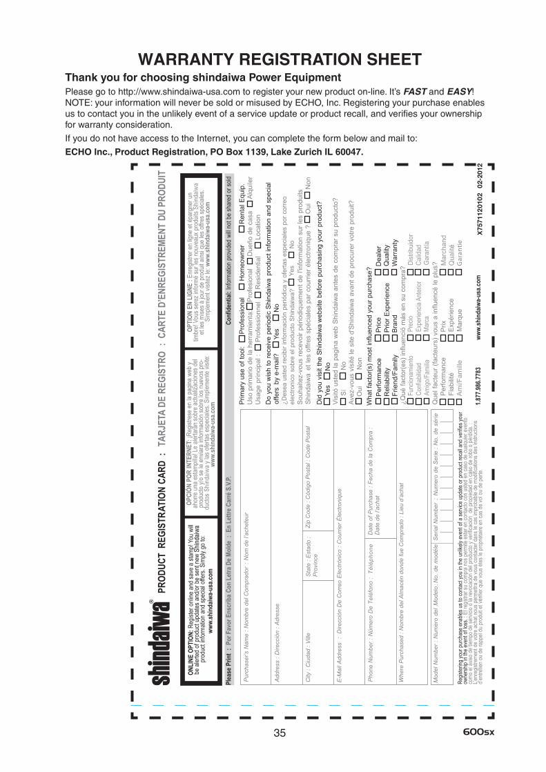
WARRANTY REGISTRATION SHEETThank you for choosing shindaiwa Power EquipmentPlease go to http://www.shindaiwa-usa.com to register your new product on-line. It’s FAST and EASY! NOTE: your information will never be sold or misused by ECHO, Inc. Registering your purchase enables us to contact you in the unlikely event of a service update or product recall, and verifies your ownership for warranty consideration.
If you do not have access to the Internet, you can complete the form below and mail to:
ECHO Inc., Product Registration, PO Box 1139, Lake Zurich IL 60047.