Embed Size (px)
Citation preview

INSTRUCTION MANUAL
MODEL W1668131⁄4" Oscillating Drill Press
Phone: 1-800-840-8420 • On-Line Technical Support: [email protected]
COPYRIGHT © 2000 BY WOODSTOCK INTERNATIONAL, INC.WARNING: NO PORTION OF THIS MANUAL MAY BE REPRODUCED IN ANY SHAPE OR FORM WITHOUT
THE WRITTEN APPROVAL OF WOODSTOCK INTERNATIONAL, INC. Printed in China

-1-
Table Of ContentsPAGE
1. INTRODUCTIONABOUT YOUR NEW DRILL PRESS ......................................................2WOODSTOCK SERVICE AND SUPPORT ................................................2WARRANTY AND RETURNS..............................................................3MACHINE SPECIFICATIONS ..............................................................3
2. SAFETY..........................................................................................4STANDARD SAFETY INSTRUCTIONS ................................................4-5DRILL PRESS SAFETY ....................................................................5ELECTRICAL REQUIREMENTS ..........................................................6AVOIDING POTENTIAL INJURIES ......................................................7
3. ASSEMBLY INSTRUCTIONS ..................................................................8BOX CONTENTS ..........................................................................8BASE AND COLUMN ......................................................................9DUST PORT ................................................................................9TABLE SUPPORT ....................................................................10-11MOUNTING TABLE ......................................................................11HEADSTOCK ..............................................................................12DRILL CHUCK ............................................................................13HANDLES..................................................................................13
4. ADJUSTMENTS ..............................................................................14SPEED CHANGE......................................................................14-15SPINDLE ADJUSTMENTS ..............................................................15OSCILLATING FEATURE ................................................................16TABLE ADJUSTMENTS ..................................................................17
5. OPERATIONS..................................................................................18TEST RUN ................................................................................18DRILL CHANGES ........................................................................19
6. MAINTENANCE................................................................................20GENERAL..................................................................................20TABLE AND BASE........................................................................20LUBRICATION ............................................................................20
7. CLOSURE ......................................................................................21PARTS BREAKDOWN AND PARTS LISTS ........................................22-23YOUR NOTES ............................................................................24
ASSEM
BLYO
PERATIO
NS
MA
INTEN
AN
CEPA
RTSA
DJU
STMEN
TSSA
FETYIN
TROD
UCTIO
N
USE THE QUICK GUIDE PAGE LABELS TO SEARCH OUT INFORMATION FAST!

-2-
INTRODUCTION
ABOUT YOUR NEW DRILL PRESSThis new Shop Fox® Oscillating Drill Press has been specially designed by WoodstockInternational, Inc. to provide many years of trouble free service. Close attention to detail,ruggedly built parts and a rigid quality control program assure safe and reliable operation.
The Shop Fox® Model W1668 is a drill press and oscillating sander in one compact machine. It iscapable of a wide variety of drilling and sanding operations. A sanding spindle is included foruse with drums ranging in size from 1" to 2" diameter and 4 1⁄4" long. Purchasing drums andsleeves will allow you to sand small or finely detailed pieces and with the oscillating feature,your abrasives will last longer and provide a smoother finish. Included are table inserts to givemaximum support for the workpiece and a dust port to connect to your dust collection system.The W1668 is packaged with a drill chuck, chuck key, motor and paddle switch with removablesafety key.
Woodstock International, Inc. is committed to customer satisfaction in providing this manual. Itis our intent to make sure all the information necessary for safety, ease of assembly, practicaluse and durability of this product be included.
If you should have any comments regarding this manual, please feel free to contact us at:
Woodstock International, Inc.P.O. Box 2309Bellingham, WA 98227
WOODSTOCK SERVICE AND SUPPORTWe stand behind our machines! In the event that a defect is found, parts are missing or questions ariseabout your machine, please contact Woodstock Service and Support at:
1-360-734-3482 or
Our knowledgeable staff will help you troubleshoot problems, send out parts or arrange warrantyreturns.
INTR
OD
UCT
ION

-3-
WARRANTY AND RETURNSWoodstock International, Inc. warrants all SHOP FOX® machinery to be free of defects from workman-ship and materials for a period of 2 years from the date of original purchase by the original owner. Thiswarranty does not apply to defects due directly or indirectly to misuse, abuse, negligence or accidents,lack of maintenance, or to repair or alterations made or specifically authorized by anyone other thanWoodstock International, Inc.
Woodstock International, Inc. will repair or replace, at its expense and at its option, the SHOP FOX®
machine or machine part which in normal use has proven to be defective, provided that the originalowner returns the product prepaid to the SHOP FOX® factory service center or authorized repair facilitydesignated by our Bellingham, WA office, with proof of their purchase of the product within 2 years, andprovides Woodstock International, Inc. reasonable opportunity to verify the alleged defect throughinspection. If it is determined there is no defect, or that the defect resulted from causes not within thescope of Woodstock International Inc.'s warranty, then the original owner must bear the cost of storingand returning the product.
This is Woodstock International, Inc.'s sole written warranty and any and all warranties that may beimplied by law, including any merchantability or fitness, for any particular purpose, are hereby limitedto the duration of this written warranty. We do not warrant that SHOP FOX® machinery complies withthe provisions of any law or acts. In no event shall Woodstock International, Inc.'s liability under this war-ranty exceed the purchase price paid for the product, and any legal actions brought against WoodstockInternational, Inc. shall be tried in the State of Washington, County of Whatcom. We shall in no eventbe liable for death, injuries to persons or property or for incidental, contingent, special or consequen-tial damages arising from the use of our products.
Every effort has been made to ensure that all SHOP FOX® machinery meets high quality and durabilitystandards. We reserve the right to change specifications at any time because of our commitment to con-tinuously improve the quality of our products.
Machine SpecificationsCapacities:
Oscillating Stoke Length............................................................................................3⁄4"Spindle Travel ......................................................................................................31⁄4''Max. Distance, Spindle to Base ....................................................................................24'' Max. Distance, Spindle to Table................................................................................171⁄4''Spindle Taper ......................................................................................................B-16Swing................................................................................................................131⁄4'' Chuck Size ........................................................................................5⁄8'' (13mm), keyedSpeeds..............................................................................................12, Belt ControlledRange of Speeds ......................250, 330, 380, 500, 590, 640, 980, 1530, 1600, 1870, 2580, 3050 RPM Drilling Capacity ..............................................................................3⁄4'' Diameter in Steel
Motor:Type ................................................................................TEFC Capacitor Start InductionHorsepower........................................................................................................3⁄4 HPPhase ⁄ Cycle ..................................................................................Single Phase ⁄ 60 HzVoltage ..............................................................................................................110VAmps......................................................................................................................9RPM ..................................................................................................................1720Power Transfer .......................................................................................... V-Belt DriveBearings ......................................................................Shielded & Lubricated Ball BearingsSwitch ................................................................Toggle ON/OFF Switch, w/ Safety Lock Tab
INTRO
DU
CTION

-4-
READ MANUAL BEFORE OPERATING MACHINEFAILURE TO FOLLOW INSTRUCTIONS BELOW WILL
RESULT IN PERSONAL INJURY
SAFETY FIRST!
1. Thoroughly read the instruction manual before operating your machine. Learn the applications,limitations and potential hazards of this machine. Keep manual in a safe, convenient place for futurereference.
2. Keep work area clean and well lighted. Clutter and inadequate lighting invite potential hazards.
3. Ground all tools. If a machine is equipped with a three-prong plug, it must be plugged into a three-hole electrical outlet or grounded extension cord. If using an adapter to aid in accommodating a two-hole receptacle, ground using a screw to a known ground.
4. Wear eye protection at all times. Use safety glasses with side shields or safety goggles, meeting thenational safety standards, while operating this machine.
5. Avoid dangerous environment. Do not operate this machine in wet or open flame environments.Airborne dust particles could cause an explosion and severe fire hazard.
6. Ensure all guards are securely in place and in working condition.
7. Make sure switch is in the “OFF” position before connecting power to machine.
8. Keep work area clean; free of clutter, grease, etc.
9. Keep children and visitors away. All visitors should be kept a safe distance away while operatingunit.
10. Childproof workshop with padlocks, master switches or by removing starter keys.
Indicates an imminently hazardous situation which, if not avoided, WILLresult in death or serious injury.
Indicates a potentially hazardous situation which, if not avoided, COULDresult in death or serious injury.
Indicates a potentially hazardous situation which, if not avoided, MAYresult in minor or moderate injury. It may also be used to alert againstunsafe practices.
This symbol is used to alert the user to useful information about properoperation of the equipment.NOTICE
SAFE
TY

1. Always operate your drill press at speeds that are appropriate for the drill bit size and the mate-rial that you are drilling.
2. Feed the drill bit evenly into the workpiece. Back the bit out of deep holes and clear the chipswith a brush after you have turned the machine off.
3. Make sure the drill bit you are using is tightened properly. Use only round, hex or triangular shankdrill bits.
4. Never do maintenance or change speeds with this machine plugged in.
5. Never use tools that are in poor condition. Cutting tools that are dull or damaged are difficult tocontrol and may cause serious injury.
6. Never drill sheet metal unless it is clamped securely to the table.
7. Work should be positioned in such a way as to avoid drilling into the table.
8. A face guard used with safety glasses is recommended.
9. Always clamp workpiece securely to table before drilling. Never hold a workpiece by hand whiledrilling.
10. Always remove handles before using oscillating feature.
11. Habits – good and bad – are hard to break. Develop good habits in your shop and safety will becomesecond-nature to you.
Additional Safety Instructions For Drill Presses
11. Disconnect machine when cleaning, adjusting or servicing.
12. Do not force tool. The machine will do a safer and better job at the rate for which it was designed.
13. Use correct tool. Do not force machine or attachment to do a job for which it was not designed.
14. Wear proper apparel. Do not wear loose clothing, neck ties, gloves, jewelry, etc.
15. Remove adjusting keys and wrenches. Before turning the machine on, make it a habit to check thatall adjusting keys and wrenches have been removed.
16. Use proper extension cord. When using an extension cord, make sure it is in good condition. Whenextension cord is 100’ and less in length, use those that are rated Hard Service (grade S) or better,and that have a conductor size of 16 A.W.G. A drop in line voltage, loss of power and overheatingcan result when using an undersized cord. The extension cord should have a ground wire and groundplug pin, as well.
17. Keep proper footing and balance at all times.
18. Do not leave machine unattended. Wait until it comes to a complete stop before leaving the area.
19. Perform machine maintenance and care. Follow lubrication and accessory attachment instructionsin the manual.
20. Keep machine away from open flame. Operating machines near pilot lights and/or open flames cre-ates a high risk if dust is dispersed in the area. Dust particles and an ignition source may cause anexplosion. Do not operate the machine in high risk areas, including but not limited to, those men-tioned above.
SAFETY
-5-
-6-
110V Operation
ELECTRICAL REQUIREMENTS
When it is necessary to use an extension cord,use the following guidelines:
•Use cords rated for Hard Service•Never exceed a length of 100 feet•Use cords with 14 ga. wire or bigger•Insure cord has a ground wire and pin•Do not use cords in need of repair
Extension Cords
Grounding
This equipment must be grounded. Verifythat any existing electrical outlet and circuityou intend to plug into is actually grounded.If it is not, it will be necessary to run a sep-arate 12 A.W.G. copper grounding wire fromthe outlet to a known ground. Under no cir-cumstances should the grounding pin fromany three-pronged plug be removed. Seriousinjury may occur.
This machine must be grounded! See Figure 1.The electrical cord supplied with the Shop Fox®
W1668 comes with a grounding pin. Do notremove it. If your outlet does not accommodatea ground pin, have it replaced by a qualifiedelectrician or have an appropriate adapterinstalled with a proven ground source. Anadapter does not ensure a grounded system ifthe adapter is not grounded.
The Shop Fox® W1668 131⁄4" Oscillating DrillPress can only be operated at 110 volts. Themotor supplied with your new drill press is ratedat 3⁄4 horse power and will draw approximately9 amps. When choosing an outlet for thismachine, consider using one with a 15 amp cir-cuit breaker or fuse. Keep in mind that a circuitbeing used by other machines or tools at thesame time will add to the electrical load beingapplied by the drill press. Add up the load rat-ings of all machines on the circuit. If this num-ber exceeds the rating of the circuit breaker orfuse, use a different outlet.
Figure 1. Typical 110V 3-prong plug and outlet.
SAFE
TY

AVOIDING POTENTIAL INJURIES
-7-
Figure 2. Never drill, holding workpiece by hand. Figure 3. Keep fingers away from spinning tool.
Fig. 4. Remove Switch Safety Key when not in use. Figure 5. Remove handles when using oscillatingmode.
SAFETY

-8-
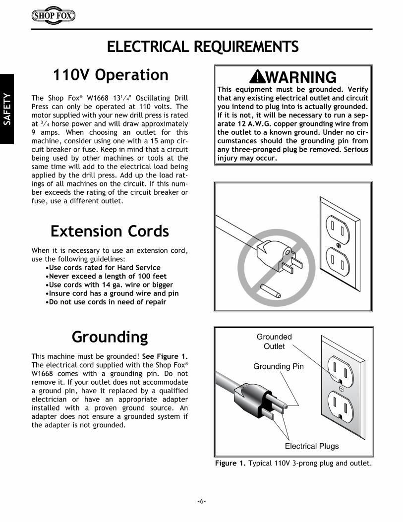
Figure 6. Components laid out for identification.
The following is a description of the components shipped with the Shop Fox® W1668 Oscillating DrillPress. It is recommended that the components be laid out in a similar fashion to those in Figure 6. Thiswill help in identification before beginning assembly. Should any part be missing, examine the packag-ing carefully and check under the belt guard. If any key parts are missing call Woodstock Internationalat 360-734-3482 or at [email protected]. Headstock Assembly2. Base3. Column4. Table5. Table Bracket6. Pinion Gear7. Clamp Shoe8. Hand Crank9. Dust Port10. Drill Chuck and Key11. Table Inserts (4)12. Spindle Handles (3)13. Belt Tension Lock Knob14. Sanding Mandrel
15. Hex Head Bolts (4)16. Phillips® Head Screws (4)17. Cap Screw18. Mandrel Washers (4)19. Allen® Wrenches (3)20. Open End Wrench21. Lock Handles (2)22. Rack23. Rack Ring24. Belt Cover Knob25. Machine Screw w/ Washer26. Sanding Sleeves27. Sanding Drums28. Mandrel Nut
ASSEMBLY INSTRUCTIONS
ASS
EMBL
Y

-9-
ASSEMBLYWhile the main components of the Shop Fox® W1668 Oscillating Drill Press are assembled at the factory,some assembly is required. The following is the recommended sequence best suited for final assembly.
TOOLS REQUIRED: You will need a 10mm, 12mm and 14mm open end wrench, a flat tipped screwdriv-er, a Phillips® screwdriver (not supplied) and a 3mm, 4mm and 5mm Allen® wrench (supplied).
Base/Column
1. Ensure machine is unplugged before begin-ning assembly!
2. Place base on a stable work bench. Makesure the work bench will handle the weightof the drill press and workpiece.
3. It is recommended that the base be securedto the bench. Otherwise a tipping hazardwill exist.
4. Clamp the base to the table once a suitablelocation is found. Use 5⁄16" lag bolts orthrough bolts with washers, lock washersand nuts. Use the mounting holes in thebase as a drill guide. Figure 7.
5. Place the column on the base and line upthe 4 mounting holes. Secure tightly withthe M10-1.5 x 25mm hex head bolts usingopen end wrench provided.
Figure 7. Using holes in base as drill guide.
Do not connect themachine to power at thistime. The drill press mustremain unplugged through-out the entire assemblyprocess. Failure to do thismay result in serious per-sonal injury.
Dust PortThe two-piece dust port is assembled to the bot-tom of the table using the four M4- 0.7 x 22mmPhillip® head screws. Figure 8.
Figure 8. Installing the dust port.
Wear safety glasses dur-ing the entire assemblyprocess. Failure to com-ply may result in seriouspersonal injury.
ASSEM
BLY

-10-Figure 11. Lock shoe Inserted into table bracket.
Figure 9. Insert the pinion gear from the inside.
Figure 10. Align setscrew with flat on pinion.
Table Support1. Thread the 12mm table lock handle 3 turns
into the table support bracket.
2. Insert the pinion into the hole on the side ofthe table support bracket from the inside,starting with the pinion shaft. Figure 9.Align setscrew in crank handle with flat,Figure 10, on pinion shaft and secure usingthe 3mm Allen® wrench provided.
3. Insert the lock shoe into the table supportbracket and secure with setscrews on eitherside. Figure 11.
Lock shoe
ASS
EMBL
Y

-11-
Figure 12. Hold rack in position while installing.
Figure 13. Inside bevel in the correct position.
Figure 14. Lock shoe in place and secured.
Table Support, Cont.4. Examine the rack and note that the gear
teeth extend further on one end than theother. Insert the rack into the table supportbracket and align with pocket. The end ofthe rack where the gear teeth are closest tothe end should be positioned down whenthe support bracket is oriented as in Figure12. The gear teeth on the rack must alsoface out.
5. Slide the table support bracket onto thecolumn while holding the rack in place.Allow the bracket to go down until the bot-tom of the rack contacts the shoulder on thecolumn support. Secure the table with thelock handle.
6. Slide the column ring onto the column with theinside bevel in the down position. Figure 13.Adjust the ring until the tip of the rack fitsinside the bevel. Tighten the setscrew on thering. Do not over tighten.
Use caution when tightening set screw. Over tight-ening will split column ring.
Mounting Table1. Thread the 10mm lock handle into the table
bracket.
2. Insert the lock shoe into the table supportbracket and secure with setscrews on eitherside. Refer to step 3 under heading TableSupport if needed.
3. Align the shaft under the table with the holeon the end of the table support bracket.Figure 14.
ASSEM
BLY

-12-
HeadStock
1. The bottom of the headstock has a pocketfor inserting the column. Position the pock-et over the column, as in Figure 15. Allowthe headstock to slide down until it stops(approximately 31⁄2").
2. Align the headstock directly over the foot ofthe base by using a plumb bob. Lay a mea-suring tape or ruler across the drill pressbase and find its center. Suspend the plumbline from the center of the headstock labelas in Figure 16 and lower the bob until it isnear the tape/ruler. Adjust headstock fromside to side until the tip is equidistant fromthe left and right sides.
3. Tighten the two setscrews in Figure 17 tosecure the headstock to the column.
The headstock repre-sents a heavy load. Seekassistance before begin-ning this step.
Figure 15. Align pocket in headstock with column.
Figure 16. Align headstock with base.
Figure 17. Tighten setscrews to secure headstock.
ASS
EMBL
Y

-13-
HandlesThree handles are supplied with your newOscillating Drill Press. Thread them into the hubas in Figure 20.
Figure 20. Spindle handle installation.
Drill Chuck
Figure 19. Securing drill chuck with screw.
Figure 18. Jaws adjusted inside chuck body.
The drill chuck is attached to the drill spindle bymeans of matched tapers and screw. To mountthe drill chuck to the spindle, carefully followthe instructions below:
1. The drill chuck and spindle must be thor-oughly cleaned before assembly. It is rec-ommended that mineral spirits be used forthis task. Refer to the safety warnings onthe container. Failure to clean the matingsurfaces may result in separation and wear.
2. Use the chuck key provided to adjust thejaws of the chuck until they are well insidethe drill chuck body. Figure 18.
3. Place the drill chuck on the spindle. Insertthe Allen® head cap screw into the hole ofthe drill chuck as in Figure 19. Tighten thescrew. The drill chuck should be seatedsecurely on the spindle at this time andshould be checked for looseness. If thechuck fails to remain secure on the spindle,repeat step 1 and 2.
Unplug machine andremove handles beforeusing the oscillating fea-ture. Handles swing dur-ing oscillating operation.
ASSEM
BLY
DO NOT use a hammer on the drill chuck toseat it onto the spindle. Damage will occur tothe oscillating mechanism.

-14-
Speed Change
ADJUSTMENTS
Unplug the drill press before changing speeds.The Oscillating Drill Press has 12 speeds rangingfrom 250 to 3050 RPM. There is a speed chartlocated under the belt guard and one on the fol-lowing page. Refer to the speed chart whilereading these instructions.
1. Loosen the belt tension lock knob.Figure 21.
2. The motor is now free to move and can bepulled toward the front of the drill press.This will take tension off the V-belts.
3. Locate the desired speed on the chart andmove the V-belts to the desired V-grooveson the motor, idler and spindle pulleys.Figure 22.
4. Push the motor toward the back of theheadstock, the motor support rod is springloaded and will follow the motor. Figure23. Tighten the lock knob.
5. Close the cover. The motor will not startuntil the cover is closed.
Figure 21. Loosening lock knob
Figure 22. Adjusting belt to desired speed.
Figure 23. Push motor toward back of machine.
Unplug the drill pressbefore changing speedsto avoid accidental startup. Failure to do this mayresult in serious personalinjury.
AD
JUST
MEN
TS

-15-
Spindle AdjustmentsYour new drill press comes fitted with a depthstop for use when drilling. Follow the instruc-tions below for use.
1. Loosen the depth collar lock knob. Figure24.
2. Rotate the depth collar to the desired depthindicated by the scale on the collar. Securethe collar with the lock knob.
3. Test the depth stop by measuring how farthe spindle actually moves when the han-dles are rotated. Figure 25. Make adjust-ment using step 1 and step 2 if needed.
The depth stop for drilling must be adjustedbefore using the oscillating feature. If thedepth stop is left adjusted for a shallow hole,damage will occur to the oscillating mecha-nism. Loosen the depth collar lock knob androtate the collar until the scale indicates 3".Tighten the lock knob.
More About Speed Change
Figure 24. Loosening collar lock knob.
Figure 25. Actual stop depth being measured.
�
The speed chart above is included to help illustrate belt changes necessary to produce a desired speed.Select the proper speed for the job at hand and find it on the speed chart above. Move the belts to theindicated location on the chart. The belt setting in the example above shows the belt in the #1 spindlepulley position and the belt is in the #7 motor pulley location. This will produce a speed of 1,870 RPM.
AD
JUSTM
ENTS

-16-
Oscillating FeatureOne of the great features of the W1668 DrillPress is its capability for oscillating sanding. Thedrill press can be converted from drilling opera-tions to sanding operations in just a few steps.
1. Unplug the drill press and remove thespindle handles.
2. Install the round rubber belt onto the topgroove in the spindle pulley and the oscil-lating pulley located between the idler pul-ley and the spindle pulley. The belt willstretch for this purpose. Figure 22.
4. Remove the 3 spindle handles. If left inplace, the operator may be struck by themwhile the spindle travels up and down.
3. Close the cover. The motor will not startuntil the cover is closed.
4. Loosen the knob for depth stop.
If the depth stop is left adjusted for a shallowhole, damage will occur to the oscillatingmechanism. Check and adjust depth stopbefore using oscillating feature.
Figure 26. Stretch the belt to fit on pulleys.
AD
JUST
MEN
TS
-17-
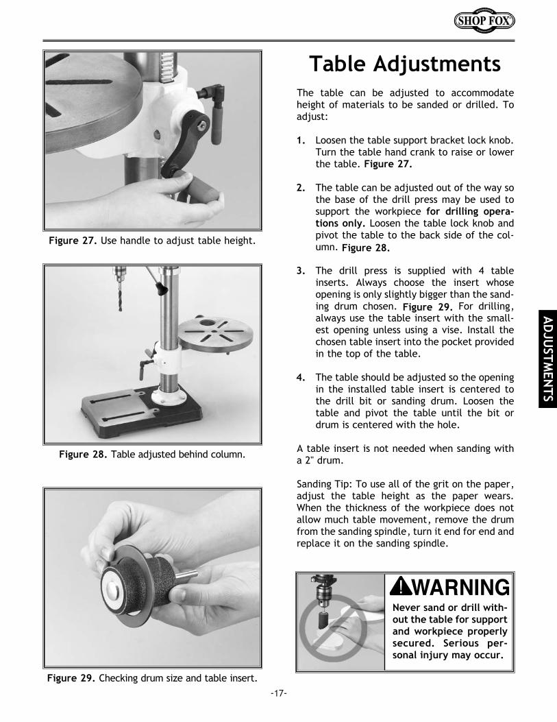
Table AdjustmentsThe table can be adjusted to accommodateheight of materials to be sanded or drilled. Toadjust:
1. Loosen the table support bracket lock knob.Turn the table hand crank to raise or lowerthe table. Figure 27.
2. The table can be adjusted out of the way sothe base of the drill press may be used tosupport the workpiece for drilling opera-tions only. Loosen the table lock knob andpivot the table to the back side of the col-umn. Figure 28.
3. The drill press is supplied with 4 tableinserts. Always choose the insert whoseopening is only slightly bigger than the sand-ing drum chosen. Figure 29. For drilling,always use the table insert with the small-est opening unless using a vise. Install thechosen table insert into the pocket providedin the top of the table.
4. The table should be adjusted so the openingin the installed table insert is centered tothe drill bit or sanding drum. Loosen thetable and pivot the table until the bit ordrum is centered with the hole.
A table insert is not needed when sanding witha 2" drum.
Sanding Tip: To use all of the grit on the paper,adjust the table height as the paper wears.When the thickness of the workpiece does notallow much table movement, remove the drumfrom the sanding spindle, turn it end for end andreplace it on the sanding spindle.
Figure 27. Use handle to adjust table height.
Figure 29. Checking drum size and table insert.
Figure 28. Table adjusted behind column.
Never sand or drill with-out the table for supportand workpiece properlysecured. Serious per-sonal injury may occur.
AD
JUSTM
ENTS

Always wear safety glass-es when operating drillpress. Failure to complymay result in serious per-sonal injury.
-18-
OPERATIONS
Once assembly is complete and adjustments aredone to your satisfaction, you are ready to testrun the machine.
Make sure the starting switch is off. The paddleis down when off. Make sure all the fastenersand lock handles are tight. Plug in the powercord. Pull the START paddle. Make sure that yourfinger is poised over the paddle,as in Figure 30,just in case there is a problem. The drill pressshould run smoothly, with little or no vibration orrubbing noises. Strange or unnatural noisesrequire you to stop the machine, investigate andcorrect before continuing. If source of unusualnoise or vibration is not readily apparent, con-tact our service department for help at 360-734-3482 or: [email protected].
Test Run
DO NOT attempt to inves-tigate or adjust themachine while it is run-ning. Wait until themachine is turned off,unplugged and all work-ing parts have come to astop before proceeding!
Figure 30. Hand poised over stop paddle.
OPE
RATI
ON
S
Installing the sanding drum spindle is identical to installing a drill bit. However, it is important to installthe paper and drum before installing the spindle into the drill chuck. See your local retailer for drumsand paper.
-19-
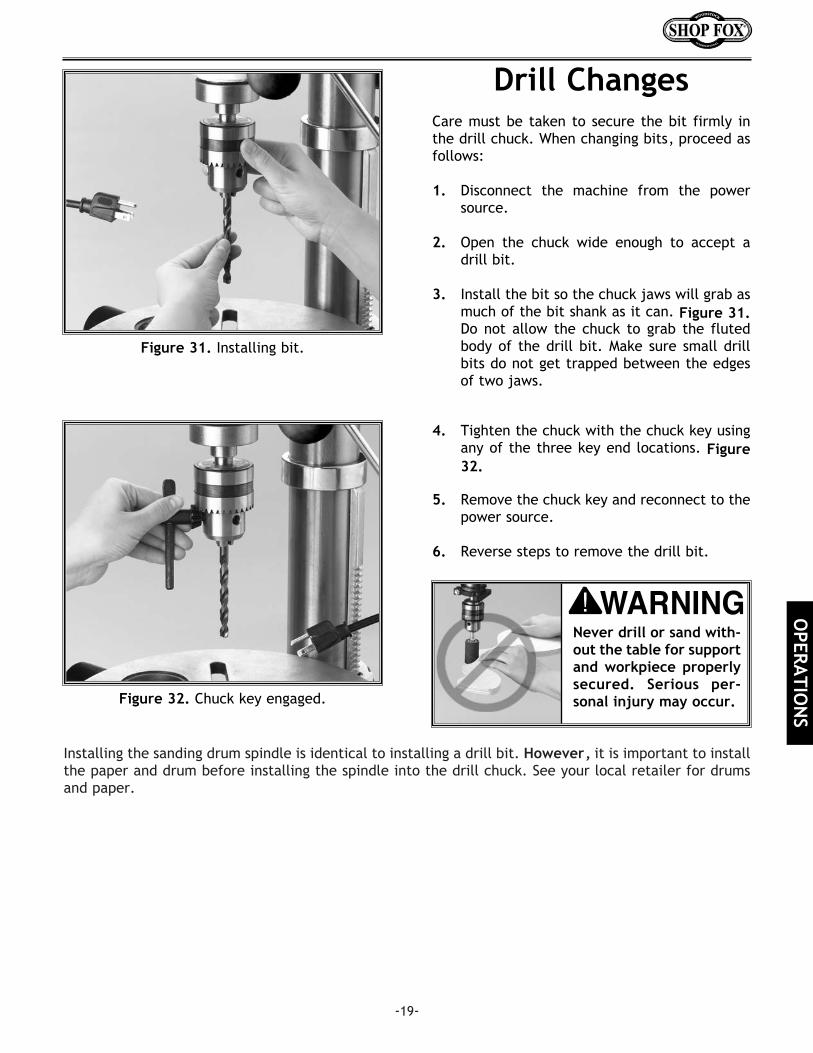
Care must be taken to secure the bit firmly inthe drill chuck. When changing bits, proceed asfollows:
1. Disconnect the machine from the powersource.
2. Open the chuck wide enough to accept adrill bit.
3. Install the bit so the chuck jaws will grab asmuch of the bit shank as it can. Figure 31.Do not allow the chuck to grab the flutedbody of the drill bit. Make sure small drillbits do not get trapped between the edgesof two jaws.
Drill Changes
Figure 32. Chuck key engaged.
Figure 31. Installing bit.
4. Tighten the chuck with the chuck key usingany of the three key end locations. Figure32.
5. Remove the chuck key and reconnect to thepower source.
6. Reverse steps to remove the drill bit.
Never drill or sand with-out the table for supportand workpiece properlysecured. Serious per-sonal injury may occur.
OPERA
TION
S
-20-
MAINTENANCE
LubricationSince all bearings are shielded and permanentlylubricated, simply leave them alone until theyneed to be replaced. Do not lubricate them.
For other items on this machine, such as thequill, table and column, an occasional shot oflight machine oil is all that is necessary. Beforeapplying lubricant, clean off sawdust and metalchips.
Your goal is to achieve adequate lubrication.Too much lubrication will attract dirt and saw-dust. Various parts of your machine could loosetheir freedom of movement as a result.
Regular periodic maintenance on your ModelW1668 Oscillating Drill Press will ensure its opti-mum performance. Make a habit of inspectingyour drill press each time you use it. Check forthe following conditions and repair or replacewhen necessary.
1. Loose mounting bolts.
2. Worn switch.
3. Worn or damaged cords and plugs.
4. Damaged V-belt.
5. Any other condition that could hamper thesafe operation of this machine.
General Table And BaseTables can be kept rust-free with regular appli-cations of products like Boeshield® T-9. For longterm storage you may want to consider productslike Kleen Bore's Rust Guardit™.Disconnect power to the
machine when perform-ing any maintenance orrepairs. Failure to do thismay result in serious per-sonal injury.
MA
INTE
NA
NCE
-21-
The following pages contain general machinedata, parts diagrams/lists and warranty/returninformation for your Shop Fox® Model W1668Drill Press.
If you need parts or help in assembling yourmachine, or if you need operational informa-tion, we encourage you to call our ServiceDepartment. Our trained service technicians willbe glad to help you.
If you have comments dealing specifically withthis manual, please write to us using the addressin the General Information. The specifications,drawings, and photographs illustrated in thismanual represent the Model W1668 as suppliedwhen the manual was prepared. However, dueto Woodstock International, Inc.’s policy of con-tinuous improvement, changes may be made atany time with no obligation on the part ofWoodstock International, Inc. Whenever possi-ble, though, we send manual updates to all own-ers of a particular tool or machine that have reg-istered their purchase with our warranty card.Should you receive one, add the new informa-tion to this manual and keep it for reference.
We have included some important safety mea-sures that are essential to this machine’s opera-tion. While most safety measures are generallyuniversal, we remind you that each workshop isdifferent and safety rules should be consideredas they apply to your specific situation.
We recommend you keep this manual for com-plete information regarding WoodstockInternational, Inc.’s warranty and return policy.Should a problem arise, we recommend that youkeep proof of purchase with your manual. If youneed additional technical information relatingto this machine, or if you need general assis-tance or replacement parts, please contact theService Department at 1-360-734-3482.
Additional information sources are necessary torealize the full potential of this machine. Tradejournals, woodworking magazines, and your
local library are good places to start. The Model W1668 was specifically designed fordrilling and drum sanding operations. DO NOTMODIFY AND/OR USE THIS DRILL PRESS FORANY OTHER PURPOSE. MODIFICATIONS ORIMPROPER USE OF THIS TOOL WILL VOID THEWARRANTY. If you are confused about anyaspect of this machine, DO NOT use it until youhave answered all your questions.
CLOSURE
As with all power tools, there is danger asso-ciated with the Model W1668 Drill Press. Usethe tool with respect and caution to lessenthe possibility of mechanical damage oroperator injury. If normal safety precautionsare overlooked or ignored, injury to theoperator or others in the area is likely.
Keep your shop “KidSafe”. Always removethe switch safety keywhen drill press is not inuse. Serious injury mayoccur.
CLOSU
RE

PART
S

-23-
55 XPB07M HEX BOLT M8-1.25 X 2556 XPB09M HEX BOLT M8-1.25 X 2057 X1668057 PUSH ROD58 X1668058 SPRING59 X1668059 RUBBER WASHER60 X1668060 OSCILLATING MECHANISM61 X1668061 ROUND DRIVE BELT62 X1668062 PULLEY COVER63 XP6203 BALL BEARING 620364 X1668064 COLLAR65 X1668065 INTERNAL SPLINE SLEEVE67 X1668067 MOTOR MOUNT68 X1668068 LOCK NUT69 X1668069 SPINDLE PULLEY70 XPS31M PHLP HD SCR M6-1.0 X 2071 XPLW03M LOCK WASHER 6MM72 XPS09M PHLP HD SCR M5-0.8 X 1073 XPW02M FLAT WASHER 5MM74 X1668074 KNOB75 X1668075 IDLER PULLEY76 X1668076 KEY77 X1668077 IDLER ARM78 X1668078 IDLER PULLEY79 XP6202 BALL BEARING 620280 X1668080 RETAINING RING81 XPW01M MOTOR V-BELT82 X1668082 SPINDLE V-BELT83 X1668083 RETAINING RING84 XP6201 BALL BEARING 620185 X1668085 RUBBER WASHER86 X1668086 QUILL87 XP6204 BALL BEARING 620488 X1668088 SPINDLE89 X1668089 DRILL CHUCK90 X1668090 CHUCK KEY91 XPSB15M CAP SCREW M5-0.8 X 2092 XPN03M HEX NUT M8-1.2593 X1668093 MANDREL94 X1668094 MANDREL WASHER 13⁄4"95 X1668095 MANDREL WASHER 7⁄8"96 X1668096 MANDREL WASHER 3⁄4"97 X1668097 OPEN END WRENCH98 XPW03M 3mm ALLEN® WRENCH 99 XPW04M 4mm ALLEN® WRENCH 100 XPW04M 5mm ALLEN® WRENCH 101 X1667MANUAL MANUAL102 X1668102 TABLE INSERT 5⁄8"103 X1668103 TABLE INSERT 1"104 X1668104 TABLE INSERT 13⁄8"105 X1668105 TABLE INSERT 17⁄8"106 X1668106 LONG HAIR SAFETY LABEL107 X1668107 GLASSES SAFETY LABEL108 X1668108 MACHINE LABEL
01 X1668001 BASE02 X1668002 COLUMN FLANGE03 X1668003 COLUMN04 X1668004 TABLE BRACKET06 XPB32M HEX BOLT M10-1.5 X 2507 X1668007 RACK08 X1668008 COLUMN RING09 XPSS01M SET SCREW M6-1.0 X 1010 X1668010 TABLE BRACKET11 X1668011 TABLE12 X1668012 WORM PINION13 X1668013 LOCK HANDLE M1014 X1668014 LOCK SHOE15 X1668015 WORM GEAR16 X1668016 LIFT HANDLE17 XPSS01M SET SCREW M6-1.0 X 10¹⁸ XPSS22M SET SCREW M4-0.7 X 1219 X1668019 LOCK HANDLE M820 X1668020 DUST PORT21 XPS33M PHLP HD SCR M4-0.7 X 2222 X1668022 HEAD CASTING23 XPN02M HEX NUT M10-1.524 X1668016 SPRING COVER25 X1668025 RETURN SPRING26 X1668026 SPRING WASHER27 X1668027 BUSHING28 XPN01M HEX NUT M6-1.029 X1668029 SPECIAL SET SCREW30 X1668030 FEED SHAFT31 X1668031 DEPTH COLLAR32 XPRP07M ROLL PIN 6MM X 2033 X1668033 FEED COLLAR34 X1668034 HANDLE BAR35 X1668035 KNOB36 X1668036 LOCK KNOB37 X1668037 POINTER38 X1668038 RIVET38C X1668038C DEPTH CHART39 XPSS16M SET SCREW M8-1.25 X 1040 XPSS13M SET SCREW M10-1.5 X 1241 XPS32M PHLP HD SCR M4-0.7 X 1042 X1668042 STAR WASHER43 XPRP07M ROLL PIN 6MM X 2044 XPS32M PHLP HD SCR M4-0.7 X 1045 X1668045 SWITCH BOX46 X1668046 LIMIT SWITCH48 X1668048 STRAIN RELIEF49 X1668049 SAFETY SWITCH50 X1668050 SWITCH KEY51 X1668051 POWER CORD52 X1668052 MOTOR 3⁄4 HP53 XPN03M HEX NUT M8-1.2554 XPW01M FLAT WASHER M8
REF PART # DESCRIPTIONREF PART # DESCRIPTION
PARTS

-24-
NOTES:

CUT
ALO
NG
DO
TTED
LIN
E
10. What stationary woodworking tools do you own? Check all that apply.
___Air Compressor ___Panel Saw___Band Saw ___Planer___Drill Press ___Power Feeder___Drum Sander ___Radial Arm Saw___Dust Collector ___Shaper___Horizontal Boring Machine ___Spindle Sander___Jointer ___Table Saw___Lathe ___Vacuum Veneer Press___Mortiser ___Wide Belt Sander___Other__________________________________________________
11. Which benchtop tools do you own? Check all that apply.
___1" x 42" Belt Sander ___6" - 8" Grinder___5" - 8" Drill Press ___Mini Lathe___8" Table Saw ___10" - 12" Thickness Planer ___8" - 10" Bandsaw ___Scroll Saw___Disc/Belt Sander ___Spindle/Belt Sander___Mini Jointer ___Power Tools___Other__________________________________________________
12. Which portable/hand held power tools do you own? Check all that apply.
___Belt Sander ___Orbital Sander___Biscuit Joiner ___Palm Sander___Circular Saw ___Portable Planer___Detail Sander ___Saber Saw___Drill/Driver ___Reciprocating Saw___Miter Saw ___Router___Other__________________________________________________
13. What machines/supplies would you like to see?
___12" Table Saw ___Radial Arm Saw___12" Jointer ___Panel Saw___Combination Planer/Jointer ___Brass Hardware___Paint & Finnish Supplies ___Lumber___Contractor’s Supplies_____other________________________________________________
14. What new accessories would you like Woodstock International to carry?__________________________________________________________________________________________________________________
15. Do you think your purchase represents good value?
___Yes ___No
16. Would you recommend Shop Fox® products to a friend?
___Yes ___No
17. Comments:_________________________________________________________________________________________________________________________________________________________________________________________________________________________________________________________________________________________
1. Where did you purchase your Shop Fox® machine?Store?______________________City?______________________
2. How did you first learn about us?
___Advertisement ___Friend___Mail order Catalog ___Local Store___World Wide Web Site
___Other__________________________________________________
3. Which of the following magazines do you subscribe to.
___American Woodworker ___Today’s Homeowner___Cabinetmaker ___WOOD___Family Handyman ___Wooden Boat___Fine Homebuilding ___Woodshop News___Fine Woodworking ___Woodsmith___Home Handyman ___Woodwork___Journal of Light Construction ___Woodworker___Old House Journal ___Woodworker’s Journal___Popular Mechanics ___Workbench___Popular Science ___American How-To___Popular Woodworking___Other__________________________________________________
4. Which of the following woodworking/remodeling shows do you watch?
___Backyard America ___The New Yankee Workshop___Home Time ___This Old House___The American Woodworker ___Woodwright’s Shop___Other__________________________________________________
5. What is your annual household income?
___$20,000-$29,999 ___$60,000-$69,999___$30,000-$39,999 ___$70,000-$79,999___$40,000-$49,999 ___$80,000-$89,999___$50,000-$59,999 ___$90,000 +
6. What is your age group?
___20-29 ___50-59___30-39 ___60-69___40-49 ___70 +
7. How long have you been a woodworker?
___0 - 2 Years ___8 - 20 Years___2 - 8 Years ___20+ Years
8. How would you rank your woodworking skills?
___Simple ___Advanced___Intermediate ___Master Craftsman
9. How many Shop Fox® machines do you own? _____________
WARRANTY CARDName __________________________________________________________________________________________Street __________________________________________________________________________________________City ____________________________________________________________________State________Zip_________Phone Number_______________________E-Mail_______________________FAX________________________MODEL #________________________________________________________________________________________
The following information is given on a voluntary basis and is strictly confidential.

TAPE ALONG EDGES--PLEASE DO NOT STAPLE
FOLD ALONG DOTTED LINE
FOLD ALONG DOTTED LINE
WOODSTOCK INTERNATIONAL, INC.P.O. BOX 2309BELLINGHAM, WA 98227-2309
PlaceStampHere