Embed Size (px)
Citation preview
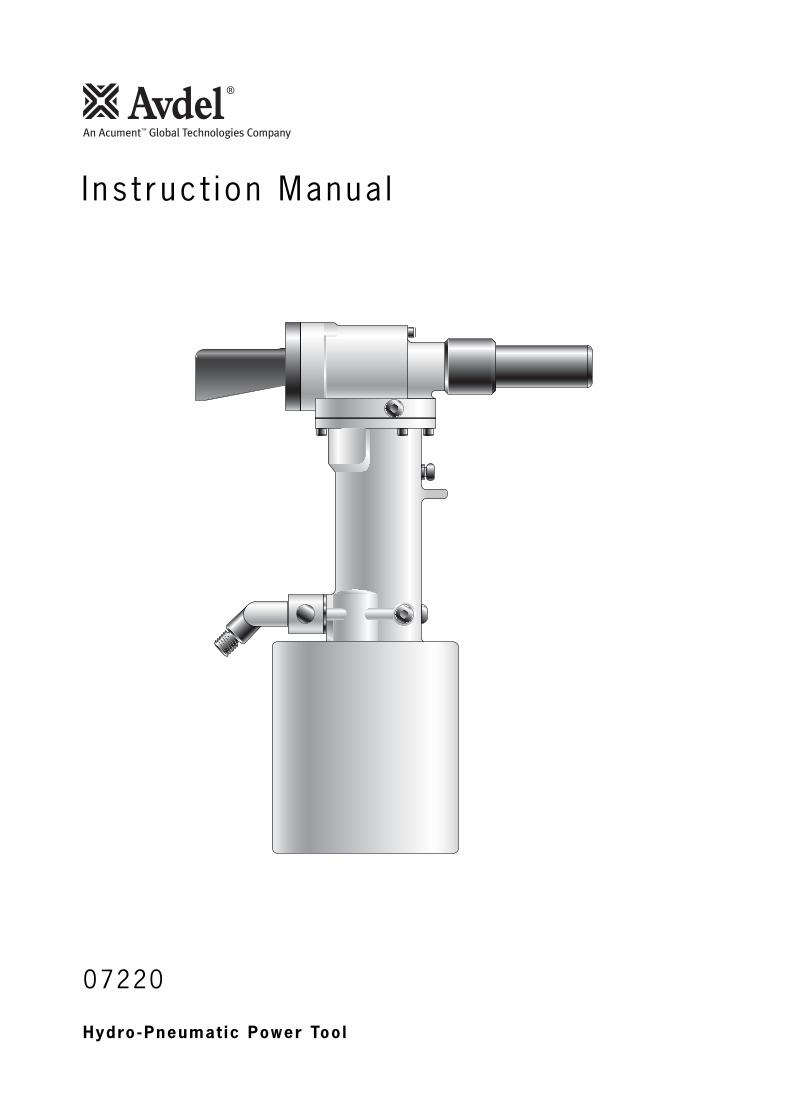
Hydro-Pneumat ic Power Too l
07220
I ns t ruc t i on Manua l

3
Contents
Safety Rules 4
SpecificationsTool Specifications 5
Intent of Use 6Tool Dimensions 6
Putting into ServiceAir Supply 7Operating Procedure 7
AccessoriesConnectors and Hose Assembly 8Collar Splitters 8Collar Splitter Assembly, Adaptor Kit (07220-09000)and Stop Kit (07229-08973) 9
Nose AssembliesSelection 10Fitting Instructions 10-11 Servicing Instructions 11Components 12
Servicing the ToolDaily / Weekly 13Moly Lithium Grease EP 3735 Safety Data 13Service Kit 14
MaintenanceDismantling Procedures 15-17
General Assembly of Base ToolGeneral Assembly 07220-00200 18 Parts List for 07220-00200 19
PrimingOil Details 20Hyspin® VG32 Oil Safety Data 20Priming Procedure 20
Fault DiagnosisSymptom, Possible Cause & Remedy 21
LIMITED WARRANTY
Avdel makes the limited warranty that it’s products will be free of defects in workmanship and materials
which occur under normal operating conditions. This Limited Warranty is contingent upon: (1) the product
being installed, maintained and operated in accordance with product literature and instructions, and (2)
confirmation by Avdel of such defect, upon inspection and testing. Avdel makes the foregoing limited
warranty for a period of twelve (12) months following Avdel’s delivery of the product to the direct purchaser
from Avdel. In the event of any breach of the foregoing warranty, the sole remedy shall be to return the
defective Goods for replacement or refund for the purchase price at Avdel’s option. THE FOREGOING
EXPRESS LIMITED WARRANTY AND REMEDY ARE EXCLUSIVE AND ARE IN LIEU OF ALL OTHER WARRANTIES
AND REMEDIES. ANY IMPLIED WARRANTY AS TO QUALITY, FITNESS FOR PURPOSE, OR MERCHANTABILITY
ARE HEREBY SPECIFICALLY DISCLAIMED AND EXCLUDED BY AVDEL.
Avdel UK Limited policy is one of continuous product development and improvement and we reserve the right to change the specification of any product without prior notice.
4
Sa fe ty Ru les
1 Do not use outside the design intent.
2 Do not use equipment with this tool/machine other than that recommended and supplied by Avdel UK Limited.
3 Any modification undertaken by the customer to the tool/machine, nose assemblies, accessories or any equipment supplied by
Avdel UK Limited or their representatives, shall be the customer’s entire responsibility. Avdel UK Limited will be pleased to advise
upon any proposed modification.
4 The tool/machine must be maintained in a safe working condition at all times and examined at regular intervals for damage and
function by trained competent personnel. Any dismantling procedure shall be undertaken only by personnel trained in Avdel UK
Limited procedures. Do not dismantle this tool/machine without prior reference to the maintenance instructions. Please contact
Avdel UK Limited with your training requirements.
5 The tool/machine shall at all times be operated in accordance with relevant Health and Safety legislation. In the U.K. the “Health
and Safety at Work etc. Act 1974” applies. Any question regarding the correct operation of the tool/machine and operator safety
should be directed to Avdel UK Limited.
6 The precautions to be observed when using this tool/machine must be explained by the customer to all operators.
7 Always disconnect the airline from the tool/machine inlet before attempting to adjust, fit or remove a nose assembly.
8 Do not operate a tool/machine that is directed towards any person(s) or the operator.
9 Always adopt a firm footing or a stable position before operating the tool/machine.
10 Ensure that vent holes do not become blocked or covered and that hoses are always in good condition.
11 The operating pressure shall not exceed 8.5 bar (125 lbf/in2).
12 Do not operate the tool without full nose equipment in place.
13 Care shall be taken to ensure that spent pintails are not allowed to create a hazard.
14 07220 tools must be fitted with an undamaged pintail deflector before operating.
15 If the 07220 tool is used in the vertical nose downward position, the pintail deflector should be rotated until the aperture is facing
away from the operator and other person(s) working in the vicinity.
16 When using the tool, the wearing of safety glasses is required both by the operator and others in the vicinity to protect against pin
ejection, should a fastener be placed ‘in air’. We recommend wearing gloves if there are sharp edges or corners on the
application.
17 Take care to avoid entanglement of loose clothes, ties, long hair, cleaning rags etc. in the moving parts of the tool which should
be kept dry and clean for best possible grip.
18 When carrying the tool from place to place keep hands away from the trigger/lever to avoid inadvertent start up.
19 Excessive contact with hydraulic oil should be avoided. To minimise the possibility of rashes, care should be taken to wash
thoroughly.
20 C.O.S.H.H. data for all hydraulic oils and lubricants is available on request from your tool supplier.
This instruction manual must be read with particular attention to the following safety rules, by any personinstalling, operating, or servicing this tool.

5
Air Pressure Minimum - Maximum 5.4-8.5 bar (80-125 lbf/in2)
Free Air Volume Required @ 5.5 bar/80 lbf/in2 14.6 litres (0.516 ft3)
Stroke Minimum 19 mm (0.75 in)
Pull Force @ 5.5 bar/80 lbf/in2 26.7 kN (6000 lbf)
Cycle time Approximately 3 seconds
Noise Level 71.8 dB(A)
Weight Without nose equipment 5.0 kg (11 lb)
Vibration Less than 2.5 m/s2
Spec i f i ca t ionsTool Spec i f icat ions
6
I n ten t o f Use
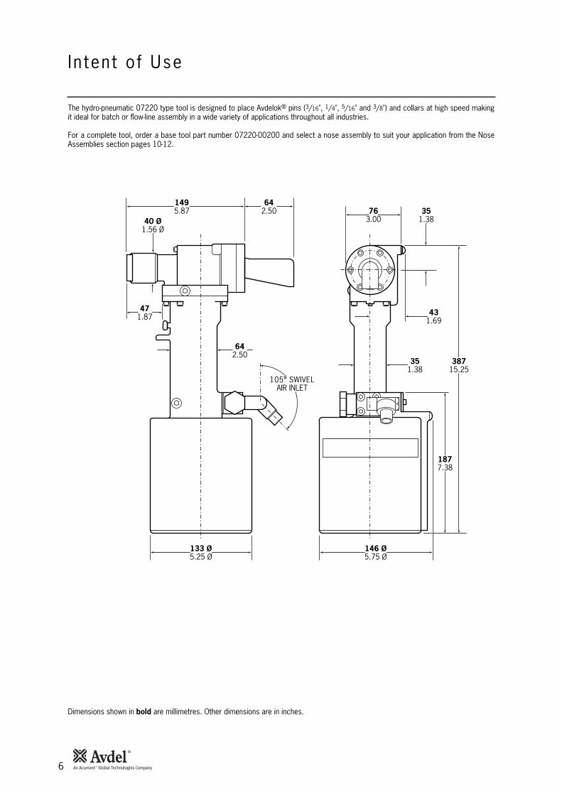
The hydro-pneumatic 07220 type tool is designed to place Avdelok® pins (3/16", 1/4", 5/16" and 3/8") and collars at high speed makingit ideal for batch or flow-line assembly in a wide variety of applications throughout all industries.
For a complete tool, order a base tool part number 07220-00200 and select a nose assembly to suit your application from the NoseAssemblies section pages 10-12.
471.87
642.50
1495.87
642.50 76
3.0035
1.38
133 Ø5.25 Ø
146 Ø5.75 Ø
1877.38
38715.25
431.69
351.38
40 Ø1.56 Ø
105O SWIVELAIR INLET
Dimensions shown in bold are millimetres. Other dimensions are in inches.
7
Operat ing Procedure
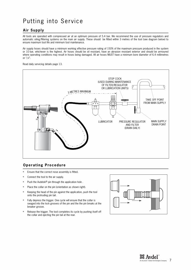
Put t ing in to Serv iceAir Supp lyAll tools are operated with compressed air at an optimum pressure of 5.4 bar. We recommend the use of pressure regulators andautomatic oiling/filtering systems on the main air supply. These should be fitted within 3 metres of the tool (see diagram below) toensure maximum tool life and minimum tool maintenance.
Air supply hoses should have a minimum working effective pressure rating of 150% of the maximum pressure produced in the systemor 10 bar, whichever is the highest. Air hoses should be oil resistant, have an abrasion resistant exterior and should be armouredwhere operating conditions may result in hoses being damaged. All air hoses MUST have a minimum bore diameter of 6.4 millimetresor 1/4”.
Read daily servicing details page 13.
• Ensure that the correct nose assembly is fitted.
• Connect the tool to the air supply.
• Push the Avdelok® pin through the application hole .
• Place the collar on the pin (orientation as shown right).
• Keeping the head of the pin against the application, push the toolonto the protruding pin tail.
• Fully depress the trigger. One cycle will ensure that the collar isswaged into the lock grooves of the pin and the the pin breaks at thebreaker groove.
• Release the trigger. The tool completes its cycle by pushing itself offthe collar and ejecting the pin tail at the rear.
86
42
0
10121416
TAKE OFF POINTFROM MAIN SUPPLY
STOP COCK(USED DURING MAINTENANCE
OF FILTER/REGULATOR OR LUBRICATION UNITS)
MAIN SUPPLYDRAIN POINT
PRESSURE REGULATORAND FILTER
(DRAIN DAILY)
LUBRICATOR
3 METRES MAXIMUM
8
Col lar Sp l i t ters
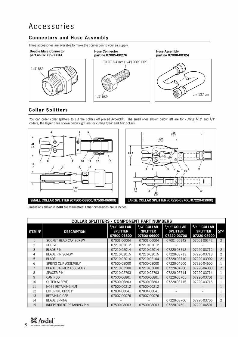
Accessor iesConnectors and Hose Assembly
Three accessories are available to make the connection to your air supply.
1/4" BSP
TO FIT 6.4 mm (1/4") BORE PIPE
1/4" BSPL = 137 cm
Double Male Connectorpart no 07005-00041
Hose Assemblypart no 07008-00324
Hose Connectorpart no 07005-00276
You can order collar splitters to cut the collars off placed Avdelok®. The small ones shown below left are for cutting 3/16” and 1/4”collars, the larger ones shown below right are for cutting 5/16” and 3/8” collars.
1074.2
6 157
85
411.6
18.7
2 10 11 12 13
1 94
3
Dimensions shown in bold are millimetres. Other dimensions are in inches.
63.52.5
1857.27
1094.31
1758 3 6 9
10
14 15
414.57
301.18
COLLAR SPLITTERS - COMPONENT PART NUMBERS
DESCRIPTION QTYITEM Nº
3/16" COLLAR SPLITTER
07500-06800
1/4" COLLAR SPLITTER
07500-06900
5/16" COLLAR SPLITTER
07220-03700
3/8 " COLLAR SPLITTER
07220-039001 SOCKET HEAD CAP SCREW 07001-00004 07001-00004 07001-00142 07001-00142 22 SLEEVE 07210-02012 07210-02012 -- -- 13 BLADE PIN 07210-02014 07210-02014 07220-03712 07220-03712 24 BLADE PIN SCREW 07210-02015 07210-02015 07220-03713 07220-03713 25 BLADE 07210-02016 07210-02104 07220-03710 07220-03902 26 SPRING CLIP ASSEMBLY 07500-08000 07500-08000 07220-04500 07220-04500 17 BLADE CARRIER ASSEMBLY 07210-02500 07210-02600 07220-04200 07220-04300 28 SPACER PIN 07210-02703 07210-02703 07220-03714 07220-03714 19 CAM ROD 07500-06801 07500-06801 07220-03701 07220-03701 1
10 OUTER SLEEVE 07500-06803 07500-06803 07220-03715 07220-03715 111 NOSE RETAINING NUT 07500-00212 07500-00212 -- -- 112 EXTERNAL CIRCLIP 07004-00041 07004-00041 -- -- 113 RETAINING CAP 07007-00076 07007-00076 -- -- 114 BLADE SPRING -- -- 07220-03706 07220-03706 215 INDEPENDENT RETAINING PIN 07500-08003 07500-08003 07220-04501 07220-04501 1
SMALL COLLAR SPLITTER (07500-06800/07500-06900) LARGE COLLAR SPLITTER (07220-03700/07220-03900)
9
Accessor ies
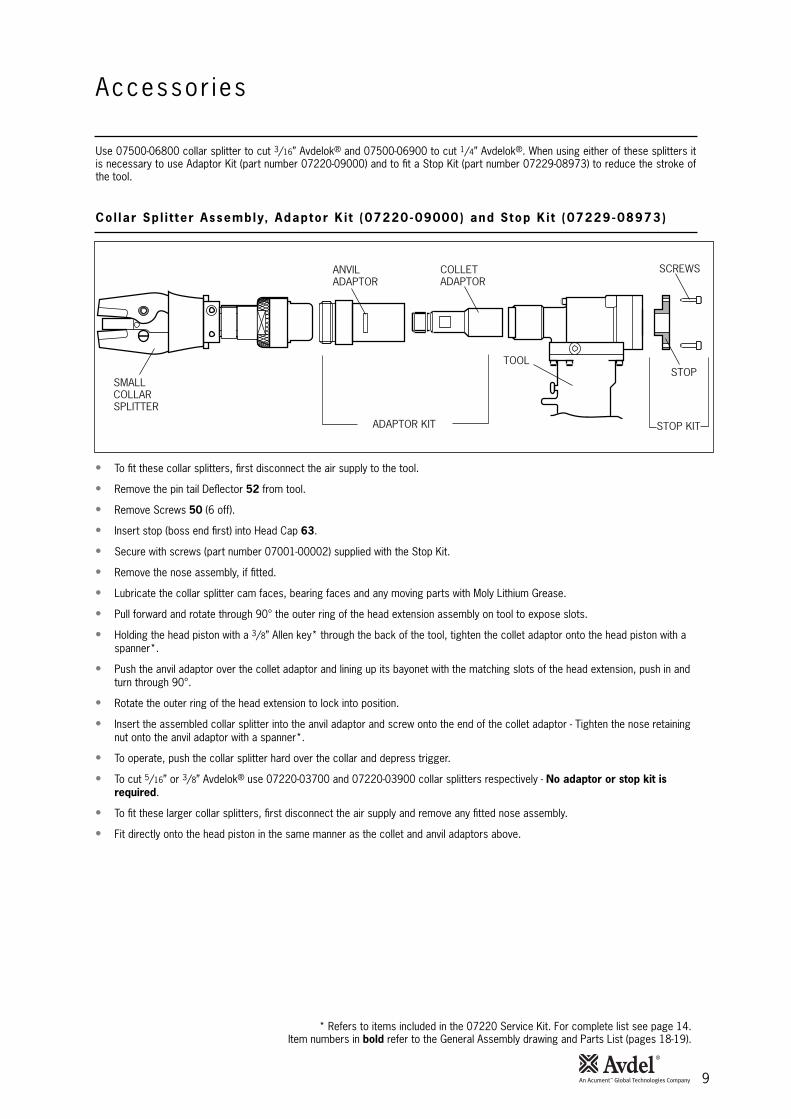
SMALLCOLLARSPLITTER
ANVILADAPTOR
COLLETADAPTOR
TOOL
ADAPTOR KIT STOP KIT
SCREWS
STOP
• To fit these collar splitters, first disconnect the air supply to the tool.
• Remove the pin tail Deflector 52 from tool.
• Remove Screws 50 (6 off).
• Insert stop (boss end first) into Head Cap 63.
• Secure with screws (part number 07001-00002) supplied with the Stop Kit.
• Remove the nose assembly, if fitted.
• Lubricate the collar splitter cam faces, bearing faces and any moving parts with Moly Lithium Grease.
• Pull forward and rotate through 90° the outer ring of the head extension assembly on tool to expose slots.
• Holding the head piston with a 3/8” Allen key* through the back of the tool, tighten the collet adaptor onto the head piston with aspanner*.
• Push the anvil adaptor over the collet adaptor and lining up its bayonet with the matching slots of the head extension, push in andturn through 90°.
• Rotate the outer ring of the head extension to lock into position.
• Insert the assembled collar splitter into the anvil adaptor and screw onto the end of the collet adaptor - Tighten the nose retainingnut onto the anvil adaptor with a spanner*.
• To operate, push the collar splitter hard over the collar and depress trigger.
• To cut 5/16” or 3/8” Avdelok® use 07220-03700 and 07220-03900 collar splitters respectively - No adaptor or stop kit isrequired.
• To fit these larger collar splitters, first disconnect the air supply and remove any fitted nose assembly.
• Fit directly onto the head piston in the same manner as the collet and anvil adaptors above.
* Refers to items included in the 07220 Service Kit. For complete list see page 14.Item numbers in bold refer to the General Assembly drawing and Parts List (pages 18-19).
Use 07500-06800 collar splitter to cut 3/16” Avdelok® and 07500-06900 to cut 1/4” Avdelok®. When using either of these splitters itis necessary to use Adaptor Kit (part number 07220-09000) and to fit a Stop Kit (part number 07229-08973) to reduce the stroke ofthe tool.
Col lar Sp l i t ter Assembly, Adaptor K i t (07220-09000) and Stop K i t (07229-08973)
10
F i t t ing Ins t ruct ions
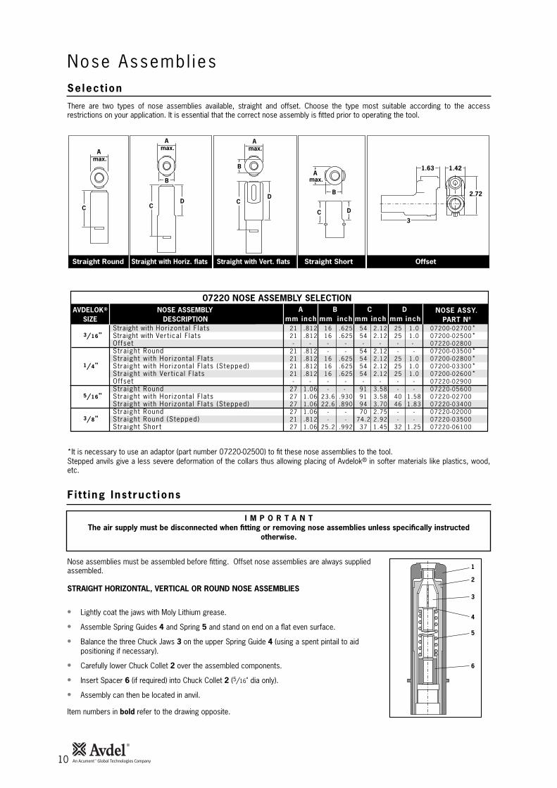
There are two types of nose assemblies available, straight and offset. Choose the type most suitable according to the accessrestrictions on your application. It is essential that the correct nose assembly is fitted prior to operating the tool.
I M P O R T A N TThe air supply must be disconnected when fitting or removing nose assemblies unless specifically instructed
otherwise.
07220 NOSE ASSEMBLY SELECTIONNOSE ASSEMBLY
DESCRIPTIONNOSE ASSY.
PART NºA AVDELOK®
SIZEB C D
mm inch inch inch inchmm mm mmStraight with Hor izonta l F lats 21 .812 16 .625 54 2.12 25 1.0 07200-02700*
3/16" Straight with Ver t ica l F lats 21 .812 16 .625 54 2.12 25 1.0 07200-02500*Of fset - - - - - - - - 07220-02800Stra ight Round 21 .812 - - 54 2.12 - - 07200-03500*Stra ight wi th Hor izonta l F lats 21 .812 16 .625 54 2.12 25 1.0 07200-02800*
1/4" Stra ight wi th Hor izonta l F lats (Stepped) 21 .812 16 .625 54 2.12 25 1.0 07200-03300*Stra ight wi th Ver t ica l F lats 21 .812 16 .625 54 2.12 25 1.0 07200-02600*Of fset - - - - - - - - 07220-02900Stra ight Round 27 1.06 - - 91 3.58 - - 07220-05600
5/16" Stra ight wi th Hor izonta l F lats 27 1.06 23.6 .930 91 3.58 40 1.58 07220-02700Stra ight wi th Hor izonta l F lats (Stepped) 27 1.06 22.6 .890 94 3.70 46 1.83 07220-03400Stra ight Round 27 1.06 - - 70 2.75 - - 07220-02000
3/8" Stra ight Round (Stepped) 21 .812 - - 74.2 2.92 - - 07220-03500Stra ight Shor t 27 1.06 25.2 .992 37 1.45 32 1.25 07220-06100
1
2
3
4
5
6
*It is necessary to use an adaptor (part number 07220-02500) to fit these nose assemblies to the tool.Stepped anvils give a less severe deformation of the collars thus allowing placing of Avdelok® in softer materials like plastics, wood,etc.
Nose assemblies must be assembled before fitting. Offset nose assemblies are always suppliedassembled.
STRAIGHT HORIZONTAL, VERTICAL OR ROUND NOSE ASSEMBLIES
• Lightly coat the jaws with Moly Lithium grease.
• Assemble Spring Guides 4 and Spring 5 and stand on end on a flat even surface.
• Balance the three Chuck Jaws 3 on the upper Spring Guide 4 (using a spent pintail to aidpositioning if necessary).
• Carefully lower Chuck Collet 2 over the assembled components.
• Insert Spacer 6 (if required) into Chuck Collet 2 (5/16" dia only).
• Assembly can then be located in anvil.
Item numbers in bold refer to the drawing opposite.
Nose Assembl iesSelect ion
Straight Round Straight with Horiz. flats Straight with Vert. flats Straight Short Offset
A max.
C
A max.
B
CD
A max.
B
CD 2.72
1.421.63
3
B
C D
A max.
11
Serv ic ing Ins t ruct ions
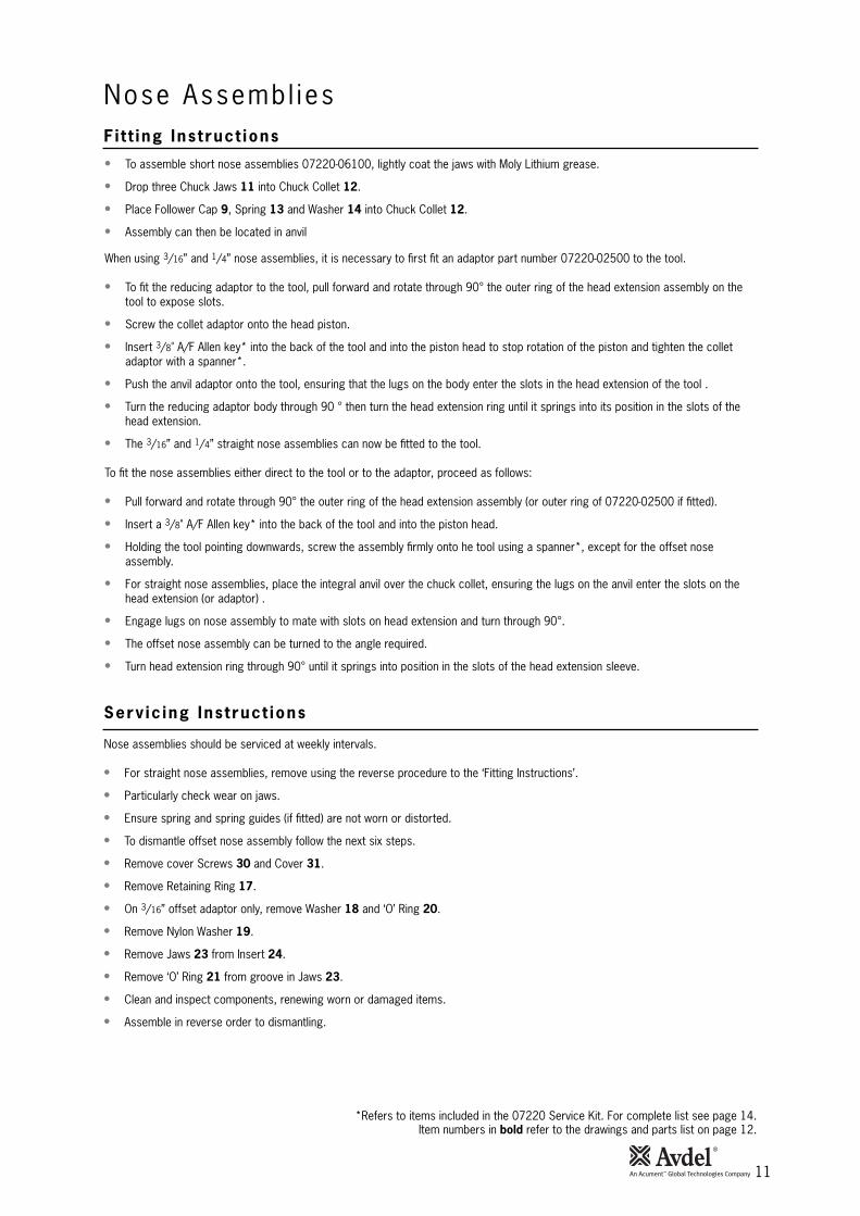
• To assemble short nose assemblies 07220-06100, lightly coat the jaws with Moly Lithium grease.
• Drop three Chuck Jaws 11 into Chuck Collet 12.
• Place Follower Cap 9, Spring 13 and Washer 14 into Chuck Collet 12.
• Assembly can then be located in anvil
When using 3/16” and 1/4” nose assemblies, it is necessary to first fit an adaptor part number 07220-02500 to the tool.
• To fit the reducing adaptor to the tool, pull forward and rotate through 90° the outer ring of the head extension assembly on thetool to expose slots.
• Screw the collet adaptor onto the head piston.
• Insert 3/8" A/F Allen key* into the back of the tool and into the piston head to stop rotation of the piston and tighten the colletadaptor with a spanner*.
• Push the anvil adaptor onto the tool, ensuring that the lugs on the body enter the slots in the head extension of the tool .
• Turn the reducing adaptor body through 90 ° then turn the head extension ring until it springs into its position in the slots of thehead extension.
• The 3/16” and 1/4” straight nose assemblies can now be fitted to the tool.
To fit the nose assemblies either direct to the tool or to the adaptor, proceed as follows:
• Pull forward and rotate through 90° the outer ring of the head extension assembly (or outer ring of 07220-02500 if fitted).
• Insert a 3/8" A/F Allen key* into the back of the tool and into the piston head.
• Holding the tool pointing downwards, screw the assembly firmly onto he tool using a spanner*, except for the offset noseassembly.
• For straight nose assemblies, place the integral anvil over the chuck collet, ensuring the lugs on the anvil enter the slots on thehead extension (or adaptor) .
• Engage lugs on nose assembly to mate with slots on head extension and turn through 90°.
• The offset nose assembly can be turned to the angle required.
• Turn head extension ring through 90° until it springs into position in the slots of the head extension sleeve.
*Refers to items included in the 07220 Service Kit. For complete list see page 14.Item numbers in bold refer to the drawings and parts list on page 12.
Nose assemblies should be serviced at weekly intervals.
• For straight nose assemblies, remove using the reverse procedure to the ‘Fitting Instructions’.
• Particularly check wear on jaws.
• Ensure spring and spring guides (if fitted) are not worn or distorted.
• To dismantle offset nose assembly follow the next six steps.
• Remove cover Screws 30 and Cover 31.
• Remove Retaining Ring 17.
• On 3/16” offset adaptor only, remove Washer 18 and ‘O’ Ring 20.
• Remove Nylon Washer 19.
• Remove Jaws 23 from Insert 24.
• Remove ‘O’ Ring 21 from groove in Jaws 23.
• Clean and inspect components, renewing worn or damaged items.
• Assemble in reverse order to dismantling.
Nose Assembl iesF i t t ing Ins t ruct ions
12
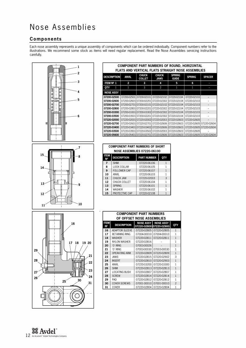
Each nose assembly represents a unique assembly of components which can be ordered individually. Component numbers refer to theillustrations. We recommend some stock as items will need regular replacement. Read the Nose Assemblies servicing instructionscarefully.
COMPONENT PART NUMBERS OF ROUND, HORIZONTAL FLATS AND VERTICAL FLATS STRAIGHT NOSE ASSEMBLIES
ITEM Nº 1 2 3 4 5 6 --
QTY 1 1 3 2 1 1 --
DESCRIPTION ANVIL CHUCK CHUCK SPRING SPRING SPACERCOLLET JAWS GUIDE
NOSE ASSY
16 ADAPTOR SLEEVE 07220-02805 07220-02805 117 RETAINING RING 07004-00010 07004-00010 118 WASHER 07220-02811 07220-02811 119 NYLON WASHER 07220-02816 -- 120 'O' RING 07003-00026 -- 121 'O' RING 07003-00030 07003-00030 122 OPERATING ARM 07220-02809 07220-02809 123 JAWS 07220-02815 07220-02902 324 INSERT 07220-02810 07220-02903 125 ANVIL 07220-03200 07220-03300 126 SHIM 07220-02813 07220-02813 127 LOCATING BUSH 07220-02807 07220-02807 128 SCREW 07220-02814 07220-02814 129 PAD 07220-02812 07220-02812 130 COVER SCREWS 07001-00010 07001-00010 231 COVER 07220-02804 07220-02804 1
COMPONENT PART NUMBERS OF OFFSET NOSE ASSEMBLIES
Nº DESCRIPTION 07220-02800 07220-02900 QTYITEM NOSE ASSY NOSE ASSY
7 SHIM 07220-06106 18 LOCK COLLAR 07220-06105 19 FOLLOWER CAP 07220-06107 1
10 ANVIL 07220-06103 111 CHUCK JAW 07220-02003 312 CHUCK COLLET 07220-06104 113 SPRING 07220-06101 114 WASHER 07220-06102 115 PROTECTIVE CAP 07220-02108 1
COMPONENT PART NUMBERS OF SHORT NOSE ASSEMBLIES 07220-06100
Nº DESCRIPTION PART NUMBER QTYITEM
16
8
9
1011
12
13
14
15
1
2
3
4
5
6
17 18 19 20
21
22
23
2425
29
28
27
2630
31
7
07200-02500 07200-02501 07200-02101 07220-02102 07220-02104 07220-02103 --07200-02600 07200-02601 07200-02201 07220-02302 07220-02104 07220-02103 --07200-02700 07200-02701 07200-02101 07220-02102 07220-02104 07220-02103 --07200-02800 07200-02801 07200-02201 07220-02302 07220-02104 07220-02103 --07200-03300 07200-03301 07200-03302 07220-02302 07220-02104 07220-02103 --07200-03500 07200-03501 07200-02201 07220-02302 07220-02104 07220-02103 --07220-02000 07220-02001 07220-02002 07220-02003 07220-02603 07220-02605 --07220-02700 07220-02601 07220-02701 07220-02606 07220-02603 07220-02605 07220-0260407220-03400 07220-03401 07220-03402 07220-02606 07220-02603 07220-02605 07220-0260407220-03500 07220-03501 07220-03502 07220-02003 07220-02603 07220-02605 --07220-05600 07220-05401 07220-02701 07220-02606 07220-02603 07220-02605 07220-02604
Nose Assembl iesComponents
13
Serv ic ing the Too l
I M P O R T A N T
The employer is responsible for ensuring that tool maintenance instructions are given to the appropriate personnel.The operator should not be involved in maintenance or repair of the tool unless properly trained.
• Daily, before use or when first putting the tool into service, pour a few drops of clean, light lubricating oil into the air inlet of the tool ifno lubricator is fitted on air supply. If the tool is in continuous use, the air hose should be disconnected from the main air supply andthe tool lubricated every two to three hours.
• Check for air leaks. If damaged, hoses and couplings should be replaced by new items.
• Check for oil leaks.
• If there is no filter on the pressure regulator, bleed the air line to clear it of accumulated dirt or water before connecting air hose totool. If a filter is fitted, drain it.
• Check that the nose equipment is correct.
• Ensure Deflector 52 is fitted to the tool.
• Check that the stroke of the tool meets the minimum specification (page 5). It is the distance travelled by the chuck collet with noseequipment fitted, measured before trigger is pressed and when trigger is fully depressed.
• Check for air leaks on air supply hose and fittings.
• Dismantle and clean nose assembly, with special attention to jaws (lubricate with Moly Lithium grease EP 3753 before refitting).
• Lubricate cam faces and bearing faces on collar splitters with Moly Lithium grease EP 3753.
Grease can be ordered as a single item, the part number is shown in the Service Kit page 14.
First Aid
SKIN:
As the grease is completely water resistant it is best removed with an approved emulsifying skin cleaner.
INGESTION:
Ensure the individual drinks 30ml Milk of Magnesia, preferably in a cup of milk.
EYES:
Irritant but not harmful. Irrigate with water and seek medical attention.
Fire
FLASH POINT: Above 220°C.
Not classified as flammable.
Suitable extinguishing media: CO2, Halon or water spray if applied by an experienced operator.
Environment
Scrape up for burning or disposal on approved site.
Handling
Use barrier cream or oil resistant gloves.
Storage
Away from heat and oxidising agent.
Item numbers in bold refer to the General Assembly drawings and Parts List pages 18-19.
Regular servicing should be carried out and a comprehensive inspection performed annually or every 500,000 cycles, whichever issooner.
Dai ly
Weekly
Moly L i th ium Grease EP 3753 Safety Data
14
Serv ic ing the Too lServ ice K i t
For all servicing we recommend the use of the Service Kit (part number 07900-02200).
07900-00043 HEAD PISTON BULLET 107900-00130 POWER PISTON BULLET 107900-00045 POWER CYLINDER SLEEVE 107900-00150 PACKING PLUG WRENCH TOOL 107900-00051 VALVE PISTON WRENCH ASSY. TOOL 107900-00054 VALVE PISTON ROD BAR 107900-00055 PISTON ROD WRENCH ASSY. 107900-00131 BASE REMOVAL TOOL ASSY. 107900-00063 BASE REMOVAL TOOL STOP RING 107900-00064 NOSE LOCKING SPRING ASSY. TOOL 107900-00065 RETURN CYLINDER ASSY. TOOL 1
07900-00068 POWER PISTON ASSY. SLEEVE 107900-00069 SWIVEL ADAPTOR BULLET 107900-00070 POWER CYLINDER PLUG 107900-00073 PRIMING PUMP ASSY. 107900-00077 'O' RING ASSY. TOOL 107900-00078 5/32" ALLEN KEY 107900-00079 3/8" ALLEN KEY 103201-00621 PIP PIN (For removal of air piston) 107007-00066 7/16" IMPACT SOCKET 107900-00490 5/8" BOX SPANNER 1
ITEM PART Nº DESCRIPTION Nº OFFSERVICE KIT
ITEM PART Nº DESCRIPTION Nº OFFSERVICE KIT (Continued)
NOTE: Spanner sizes are measured 'across flats' unless otherwise specified.
15
Dismant l ing Procedures
Main tenance
Every 500,000 cycles the tool should be completely dismantled and new components should be used where worn, damaged or whenrecommended. All ‘O’ rings and seals should be renewed and lubricated with Moly Lithium grease EP 3753 before assembling.
I M P O R T A N TSafety Instructions appear on page 4.
The employer is responsible for ensuring that tool maintenance instructions are given to the appropriatepersonnel.
The operator should not be involved in maintenance or repair of the tool unless properly trained.
For total tool servicing we advise that you proceed with dismantling of sub-assemblies in the order shown below:
HEAD ASSEMBLY
• Connect tool to air supply.• Depress Trigger 87 and hold.• Disconnect air supply and release trigger.• Remove Screws 50 using Allen key*.• Lift off Head Assembly 53.• Remove Screw 75 using Allen key* and remove Washer 74.• Allow oil to drain.• Remove Gasket 51 and ‘O’ Ring 95.• Hold Head Assembly 53 in vice fitted with soft jaws, with Return Cylinder 56 uppermost.• Place return cylinder assembly tool* over Return Cylinder 56 and tighten clinch screw.• Use tool to unscrew cylinder from Head Assembly 53.• Remove tool.• Withdraw Return Piston 58 and Spring 59.• Remove ‘O’ Ring 60.• Pull pintail deflector from Deflector Fitting 61.• Remove Deflector Fitting 61 by removing Retaining Ring 65.• Remove six Screws 50 using Allen key *.• Slightly rotate Head Cap 17(63) and pull out.• Remove ‘O’ Ring 64, Lip Seal 15 and Wiper Ring 14 (66,67).• Place a flat rectangular bar approximately 1/2" thick in slot of Head Extension Assembly 55 and unscrew from Head Sub-assembly
68.• Remove Thrust Washer 77 and Shim 76.• Gently tap Head Piston 54 out of rear of Head Assembly 53.• Remove Lip Seal 16 (72,73) from Head Sub-assembly 68.• Remove Anti-extrusion Ring 71 and Seal 70 from Head Piston 54.• Pressure Regulating Screw 85 is factory set and should not normally be disturbed. If attention is required note number of turns of
Pressure Regulating Screw 85 necessary to bring the screw level with surface of head cylinder.• Remove Pressure Regulating Screw 85 and withdraw Spring 84, Spring Guide 83 and steel Ball 82.• Using a suitable screwdriver, engage slot of Ball Seat 78 and unscrew from head cylinder.• Remove Seal 79 from head cylinder.• Complete assembly in reverse order to dismantling. Ensure Spring Guide 83 is fitted correct way round and that Pressure
Regulating Screw 85 is in its original position. When assembling Head Piston 54 into Head Sub-assembly 68 use head pistonbullet* fitted over piston threads.
• When re-attaching Head Assembly 53 to Handle Assembly 1, care must be taken to ensure correct alignment between Gasket 51,‘O’ Ring 95 and Screws 50.
• To assist with alignment, apply a thin film of Molycote 111 grease to the upper surface of Gasket 51 and then stick the gasket tothe base of Head Assembly 53, ensuring correct alignment with the ‘O’ Ring 95 and screw holes.
• Any overlap between Gasket 51 and ‘O’ Ring 95 must be avoided.• The grease will hold Gasket 51 in the correct position when attaching head Assembly 53 to Handle Assembly 1.
The airline must be disconnected before any servicing or dismantling is attempted, unless specifically instructed otherwise.It is recommended that any dismantling operation be carried out in clean conditions.
* Items in parenthasis for tools prior to ser. no 14000.* Refers to items included in the 07220 Service Kit. For complete list see page 14.
Item numbers in bold refer to the General Assembly drawing and Parts List (pages 18-19).

16
Ma in tenanceDismant l ing Procedures
* Refers to items included in the 07220 Service Kit. For complete list see page 14.Item numbers in bold refer to General Assembly drawings and Parts List (pages 18-19).
HANDLE ASSEMBLY
• Connect tool to air supply.
• Depress Trigger 87 and hold.
• Disconnect air supply and release trigger.
• Remove Screws 50 using Allen key*.
• Lift off Head Assembly 53.
• Poor oil from handle into suitable container.
• Using a spanner, remove Swivel Bolt 23.
• Using Allen key*, remove four Screws 44 and lift off Valve Assembly 18.
• Stand handle upside down and remove Retaining Ring 38 using a suitable screwdriver.
• Lift out Base Cover 35.
• Using a suitable screwdriver remove Retaining Ring 36.
• Locate stop ring* over base of Handle 2.
• Place base removal tool* over base of Handle 2 and align two screws in removal tool with two tapped holes in Handle Base 34.
• Engage and tighten two screws provided. Screw down three remaining screws until Handle Base 34 is released.
• Remove Retaining Ring 33, Buffer Assembly 32 and ‘O’ Ring 37 from Handle Base 34.
• To remove Air Piston Sub-assembly 40 insert piston rod wrench* into top of power Piston Assembly 47.
• Using a suitable 3/8" socket and extension bar unscrew Nut 39.
• Tap power Piston Assembly 47 out of Air Piston Sub-assembly 40.
• Insert pip pin* into hole in Air Piston Sub-assembly 40 and withdraw air piston sub-assembly from Handle 2.
• Remove Seal 31 from Air Piston Sub-assembly 40.
• Push power Piston Assembly 47 out of top of Handle 2. Remove Seal 48 and Anti-extrusion Ring 49.
• Place Handle 2, air cylinder upwards in bench vice fitted with soft jaws.
• Using packing plug wrench tool*, engage dogs on tool into holes in Packing Plug 3 and unscrew.
• Remove ‘O’ Ring 13 from Handle 2.
• Remove Retaining Rings 10 from both ends of Packing Plug 3 and lift out Washer 6, Seal 12 and Anti-extrusion Ring 5 from topPacking Plug 3.
• Lift out Washer 6 and ‘O’ Ring 4 from bottom of Packing Plug 3.
• Remove Handle 2 from bench vice and stand upright, i.e. on air cylinder.
• Using power cylinder installation and removal tool*, tap Power Cylinder 8 downwards until free.
• Remove Seal 9 from Power Cylinder 8 and ‘O’ Ring 11.
• Remove Trigger Sleeve 89 with box spanner*.
• Pull out Trigger 87 and remove ‘O’ Ring 88.
• Assemble Seal 9 onto Power Cylinder 8 using ‘O’ ring assembly tool*.
• Before fitting Power Cylinder 8 to Handle 2, place power piston assembly sleeve* over Seal 9. Replace ‘O’ Ring 11 onto PowerCylinder 8.
• Before fitting power Piston Assembly 47, fit power piston bullet* over rod and power piston assembly sleeve* over piston.
• Before fitting ‘O’ Rings 24 to Swivel Bolt 23, place swivel adaptor bullet* over swivel bolt threads.
• Complete assembly in reverse order to dismantling. Ensure seals and anti-extrusion rings are fitted in the right order.
• When re-attaching Head Assembly 53 to Handle Assembly 1, care must be taken to ensure correct alignment between Gasket 51,‘O’ Ring 95 and Screws 50.
• To assist with alignment, apply a thin coat of Molycote 111 grease to the upper surface of Gasket 51 and then stick the gasket tothe base of Head assembly 53 ensuring correct alignment with ‘O’ Ring 95 and the screw holes.
• Any overlap between Gasket 51 and ‘O’ Ring 95 must be avoided.
• The grease will hold Gasket 51 in the correct position when attaching head Assembly 53 to Handle Assembly 1.
17
Ma in tenanceDismant l ing Procedures
* Refers to items included in the 07220 Service Kit. For complete list see page 14.Item numbers in bold refer to General Assembly drawings and Parts List (pages 18-19).
I M P O R T A N T
Check the tool against daily and weekly servicing.
Priming is ALWAYS necessary after the tool has been dismantled and prior to operating.
AIR VALVE
• Remove Valve Seat 45 and Gasket 41 together with Slide Valve 42 and slide valve Spring 43.
• Unscrew Valve Stop 20 from Valve Block 19 using suitable spanner*.
• Withdraw Spring 21.
• Unscrew Valve Cylinder Cap 30 from Valve Block 19 and remove Gasket 28.
• Insert suitable rod into hole in Valve Shaft 26. Engage dogs of valve piston wrench assembly tool* in holes of Valve Piston 29 andunscrew.
• Remove ‘O’ Ring 27.
• Assemble in reverse order to dismantling.
SILENCER
• Remove two Screws 91 and extract sintered Silencer 93 and neoprene Gasket 90.
• Thoroughly clean silencer or renew if worn before refitting.
18
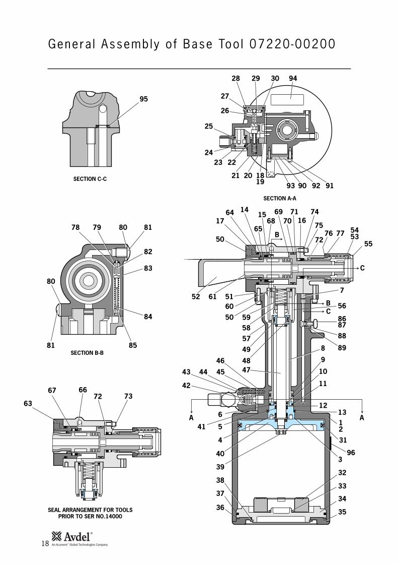
Genera l Assembly o f Base Too l 07220-00200
95
78 79 80
SEAL ARRANGEMENT FOR TOOLSPRIOR TO SER NO.14000
SECTION B-B
SECTION C-C
SECTION A-A
81
82
83
84
8581
80
28
27
26
25
2423 22
21 2090 92 91
29 9430
93
B
BC
C
32
AA
52
50
1764
65
1516
1918
687169 74
7075
7672
77 5354
55
61
14
56
8687
88
89
1312
3
33
34
35
31
8
9
10
11
12
751
50
60
57
49
47
6
454443
42
541
4
40
39
38
37
36
4846
96
5958
63
6672 73
67
19
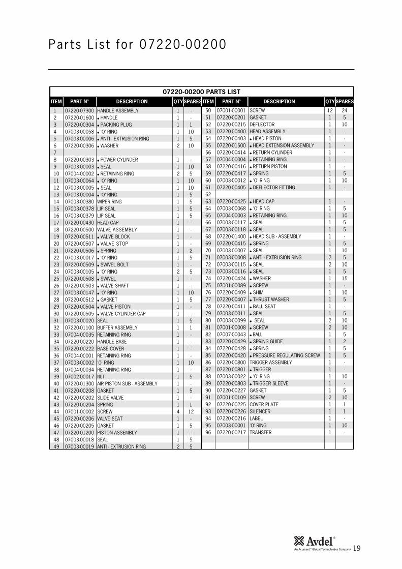
Par ts L is t for 07220-00200
50 07001-00001 SCREW 12 2451 07220-00201 GASKET 1 552 07220-00215 DEFLECTOR 1 1053 07220-00400 HEAD ASSEMBLY 1 -54 07220-00403 ● HEAD PISTON 1 -55 07220-01500 ● HEAD EXTENSION ASSEMBLY 1 -56 07220-00414 ● RETURN CYLINDER 1 -57 07004-00004 ● RETAINING RING 1 -58 07220-00416 ● RETURN PISTON 1 -59 07220-00417 ● SPRING 1 560 07003-00012 ● 'O' RING 1 1061 07220-00405 ● DEFLECTOR FITTING 1 -6263 07220-00425 ● HEAD CAP 1 -64 07003-00068 ● 'O' RING 1 565 07004-00003 ● RETAINING RING 1 1066 07003-00117 ● SEAL 1 567 07003-00118 ● SEAL 1 568 07220-01400 ● HEAD SUB - ASSEMBLY 1 -69 07220-00415 ● SPRING 1 570 07003-00007 ● SEAL 1 1071 07003-00008 ● ANTI - EXTRUSION RING 2 572 07003-00115 ● SEAL 2 1073 07003-00116 ● SEAL 1 574 07220-00424 ● WASHER 1 1575 07001-00089 ● SCREW 1 -76 07220-00409 ● SHIM 1 1077 07220-00407 ● THRUST WASHER 1 578 07220-00411 ● BALL SEAT 1 -79 07003-00011 ● SEAL 1 580 07003-00099 ● SEAL 2 1081 07001-00008 ● SCREW 2 1082 07007-00043 ● BALL 1 583 07220-00429 ● SPRING GUIDE 1 284 07220-00428 ● SPRING 1 585 07220-00420 ● PRESSURE REGULATING SCREW 1 586 07220-00800 TRIGGER ASSEMBLY 1 -87 07220-00801 ● TRIGGER 1 -88 07003-00022 ● 'O' RING 1 1089 07220-00803 ● TRIGGER SLEEVE 1 -90 07220-00227 GASKET 1 591 07001-00109 SCREW 2 1092 07220-00225 COVER PLATE 1 193 07220-00226 SILENCER 1 194 07220-00216 LABEL 1 -95 07003-00001 'O' RING 1 1096 07220-00217 TRANSFER 1 -
1 07220-07300 HANDLE ASSEMBLY 1 -2 07220-01600 ● HANDLE 1 -3 07220-00304 ● PACKING PLUG 1 14 07003-00058 ● 'O' RING 1 105 07003-00006 ● ANTI - EXTRUSION RING 1 56 07220-00306 ● WASHER 2 1078 07220-00303 ● POWER CYLINDER 1 -9 07003-00003 ● SEAL 1 1010 07004-00002 ● RETAINING RING 2 511 07003-00064 ● 'O' RING 1 1012 07003-00005 ● SEAL 1 1013 07003-00004 ● 'O' RING 1 514 07003-00380 WIPER RING 1 515 07003-00378 LIP SEAL 1 516 07003-00379 LIP SEAL 1 517 07220-00430 HEAD CAP 1 -18 07220-00500 VALVE ASSEMBLY 1 -19 07220-00511 ● VALVE BLOCK 1 -20 07220-00507 ● VALVE STOP 1 -21 07220-00506 ● SPRING 1 222 07003-00017 ● 'O' RING 1 523 07220-00509 ● SWIVEL BOLT 1 -24 07003-00105 ● 'O' RING 2 525 07220-00508 ● SWIVEL 1 -26 07220-00503 ● VALVE SHAFT 1 -27 07003-00147 ● 'O' RING 1 1028 07220-00512 ● GASKET 1 529 07220-00504 ● VALVE PISTON 1 -30 07220-00505 ● VALVE CYLINDER CAP 1 -31 07003-00020 SEAL 1 532 07220-01100 BUFFER ASSEMBLY 1 133 07004-00035 RETAINING RING 1 -34 07220-00220 HANDLE BASE 1 -35 07220-00222 BASE COVER 1 -36 07004-00001 RETAINING RING 1 -37 07003-00002 'O' RING 1 1038 07004-00034 RETAINING RING 1 -39 07002-00017 NUT 1 540 07220-01300 AIR PISTON SUB - ASSEMBLY 1 -41 07220-00208 GASKET 1 542 07220-00202 SLIDE VALVE 1 -43 07220-00204 SPRING 1 144 07001-00002 SCREW 4 1245 07220-00206 VALVE SEAT 1 -46 07220-00205 GASKET 1 547 07220-01200 PISTON ASSEMBLY 1 -48 07003-00018 SEAL 1 549 07003-00019 ANTI - EXTRUSION RING 2 5
ITEM PART Nº DESCRIPTION QTYSPARES ITEM PART Nº DESCRIPTION QTYSPARES
07220-00200 PARTS LIST
20
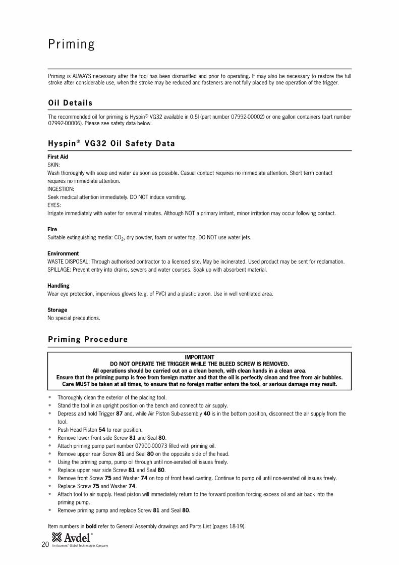
Pr im ing
Priming is ALWAYS necessary after the tool has been dismantled and prior to operating. It may also be necessary to restore the fullstroke after considerable use, when the stroke may be reduced and fasteners are not fully placed by one operation of the trigger.
IMPORTANTDO NOT OPERATE THE TRIGGER WHILE THE BLEED SCREW IS REMOVED.
All operations should be carried out on a clean bench, with clean hands in a clean area.Ensure that the priming pump is free from foreign matter and that the oil is perfectly clean and free from air bubbles.
Care MUST be taken at all times, to ensure that no foreign matter enters the tool, or serious damage may result.
• Thoroughly clean the exterior of the placing tool.• Stand the tool in an upright position on the bench and connect to air supply.• Depress and hold Trigger 87 and, while Air Piston Sub-assembly 40 is in the bottom position, disconnect the air supply from the
tool.• Push Head Piston 54 to rear position.• Remove lower front side Screw 81 and Seal 80.• Attach priming pump part number 07900-00073 filled with priming oil.• Remove upper rear Screw 81 and Seal 80 on the opposite side of the head.• Using the priming pump, pump oil through until non-aerated oil issues freely.• Replace upper rear side Screw 81 and Seal 80.• Remove front Screw 75 and Washer 74 on top of front head casting. Continue to pump oil until non-aerated oil issues freely.• Replace Screw 75 and Washer 74.• Attach tool to air supply. Head piston will immediately return to the forward position forcing excess oil and air back into the
priming pump.• Remove priming pump and replace Screw 81 and Seal 80.
Item numbers in bold refer to General Assembly drawings and Parts List (pages 18-19).
The recommended oil for priming is Hyspin® VG32 available in 0.5l (part number 07992-00002) or one gallon containers (part number07992-00006). Please see safety data below.
First AidSKIN:Wash thoroughly with soap and water as soon as possible. Casual contact requires no immediate attention. Short term contactrequires no immediate attention.INGESTION:Seek medical attention immediately. DO NOT induce vomiting.EYES:Irrigate immediately with water for several minutes. Although NOT a primary irritant, minor irritation may occur following contact.
FireSuitable extinguishing media: CO2, dry powder, foam or water fog. DO NOT use water jets.
EnvironmentWASTE DISPOSAL: Through authorised contractor to a licensed site. May be incinerated. Used product may be sent for reclamation.SPILLAGE: Prevent entry into drains, sewers and water courses. Soak up with absorbent material.
HandlingWear eye protection, impervious gloves (e.g. of PVC) and a plastic apron. Use in well ventilated area.
StorageNo special precautions.
Oi l Deta i l s
Hysp in ® VG32 Oi l Safety Data
Pr iming Procedure

21
Fau l t D iagnos is
Short stroke or Reduced air pressure Adjust air pressure. Check for leaks 7
incomplete return Leaking head/handle gasket Replace gasket
Oil level in tool low or air in oil Reprime tool 20
Tool fails to grip Incorrect nose assembly fitted Change to correct nose assembly 10
Lockbolt Broken jaws in nose assembly Replace 11
Worn or dirty jaws Clean or renew as necessary 11
Tool fails to break Insufficient air pressure Adjust air pressure/air leaks 7
Lockbolt Incorrect length of bolt Change to correct length bolt
Tool requires priming Reprime tool 20
Tool exhaust silencer dirty Clean silencer
Control valve dirty Remove/clean valve
Tool fails to swage Insufficient air pressure Adjust air pressure 7
collar Worn anvils Replace
Tool requires priming Reprime tool 20
Swaging anvil cracked Replace
Incorrect length of bolt Change to correct length bolt
Tool slows and fails Exhaust silencer dirty Clean silencer 17
to actuate Control valve dirty Remove and clean valve
Other symptoms or failures should be reported to your local Avdel® authorised distributor or repair centre.
SYMPTOM POSSIBLE CAUSE REMEDY PAGE REFSymptom Poss ib le Cause Remedy Page Ref

22
Notes
23
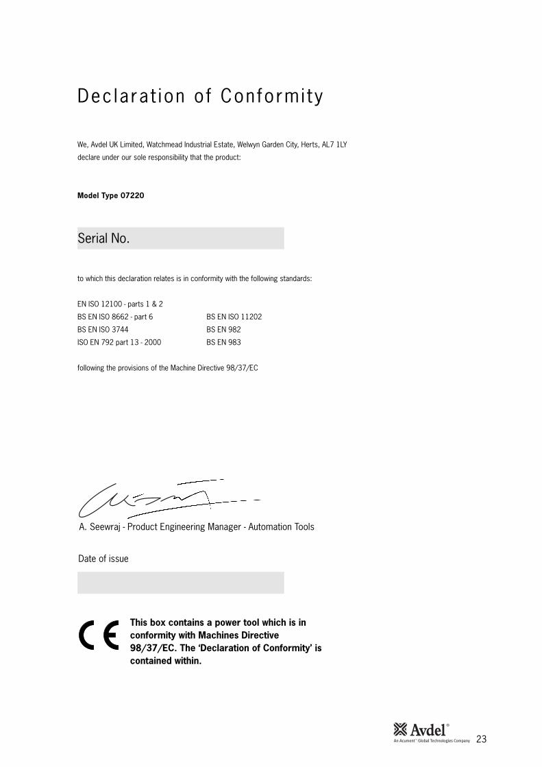
Dec lara t ion o f Conformi ty
We, Avdel UK Limited, Watchmead Industrial Estate, Welwyn Garden City, Herts, AL7 1LY
declare under our sole responsibility that the product:
Model Type 07220
Serial No. ................................................
to which this declaration relates is in conformity with the following standards:
EN ISO 12100 - parts 1 & 2
BS EN ISO 8662 - part 6 BS EN ISO 11202
BS EN ISO 3744 BS EN 982
ISO EN 792 part 13 - 2000 BS EN 983
following the provisions of the Machine Directive 98/37/EC
Date of issue
This box contains a power tool which is inconformity with Machines Directive98/37/EC. The ‘Declaration of Conformity’ iscontained within.
A. Seewraj - Product Engineering Manager - Automation Tools
www.avdel-global.com
© 2
00
8 A
cu
me
nt
Inte
lle
ctu
al
Pro
pe
rtie
s,
LL
C P
rin
ted
F
eb
rua
ry 2
00
9
Avdel® and Avdelok® are trademarks of Avdel UK Limited.
AUSTRALIA
Acument Australia Pty Ltd.
891 Wellington Road
Rowville, Victoria 3178
Tel: +61 3 9765 6400
Fax: +61 3 9765 6445
Email: [email protected]
CANADA
Acument Canada Ltd.
87 Disco Road
Rexdale
Ontario M9W 1M3
Tel: +1 416 679 0622
Fax: +1 416 679 0678
Email: [email protected]
CHINA
Acument China Ltd.
RM 1708, 17/F., Nanyang Plaza,
57 Hung To Rd., Kwun Tong
Hong Kong
Tel: +852 2950 0631
Fax: +852 2950 0022
Email: [email protected]
FRANCE
Avdel France S.A.S.
33 bis, rue des Ardennes
BP4
75921 Paris Cedex 19
Tel: +33 (0) 1 4040 8000
Fax: +33 (0) 1 4208 2450
Email: [email protected]
GERMANY
Avdel Deutschland GmbH
Klusriede 24
30851 Langenhagen
Tel: +49 (0) 511 7288 0
Fax: +49 (0) 511 7288 133
Email: [email protected]
ITALY
Avdel Italia S.r.l.
Viale Lombardia 51/53
20047 Brugherio (MI)
Tel: +39 039 289911
Fax: +39 039 2873079
Email: [email protected]
JAPAN
Acument Japan Kabushiki Kaisha
Center Minami SKY,
3-1 Chigasaki-Chuo, Tsuzuki-ku,
Yokohama-city, Kanagawa Prefecture
Japan 224-0032
Tel: +81 45 947 1200
Fax: +81 45 947 1205
Email: [email protected]
SINGAPORE
Acument Asia Pacific (Pte) Ltd.
#05-03/06 Techlink
31 Kaki Bukit Road 3
Singapore, 417818
Tel: +65 6840 7431
Fax: +65 6840 7409
Email: [email protected]
SOUTH KOREA
Acument Korea Ltd.
212-4, Suyang-Ri,
Silchon-Eup, Kwangju-City,
Kyunggi-Do, Korea, 464-874
Tel: +82 31 798 6340
Fax: +82 31 798 6342
Email: [email protected]
SPAIN
Avdel Spain S.A.
C/ Puerto de la Morcuera, 14
Poligono Industrial Prado Overa
Ctra. de Toledo, km 7,8
28919 Leganés (Madrid)
Tel: +34 (0) 91 3416767
Fax: +34 (0) 91 3416740
Email: [email protected]
UNITED KINGDOM
Avdel UK Limited
Pacific House
2 Swiftfields
Watchmead Industrial Estate
Welwyn Garden City
Hertfordshire
AL7 1LY
Tel: +44 (0) 1707 292000
Fax: +44 (0) 1707 292199
Email: [email protected]
USA
Avdel LLC
614 NC Highway 200 South
Stanfield,
North Carolina 28163
Tel: +1 704 888-7100
Fax: +1 704 888-0258
Email: [email protected]
Manual No. Issue Change Note No.
07900-00648
A2 03/263
B 07/044
B2 07/103
B3 08/326
![Tebu-Crop 3 - Sharda USA6].pdf · Spray Volume: Apply Tebu-Crop 3.6F with ground or aerial equipment using sufficient volume of spray to provide thorough coverage. Apply Tebu-Crop](https://img.pdfslide.us/doc/110x75/5e435157f943b960f57efcd6/tebu-crop-3-sharda-6pdf-spray-volume-apply-tebu-crop-36f-with-ground-or.jpg)