Embed Size (px)
Citation preview
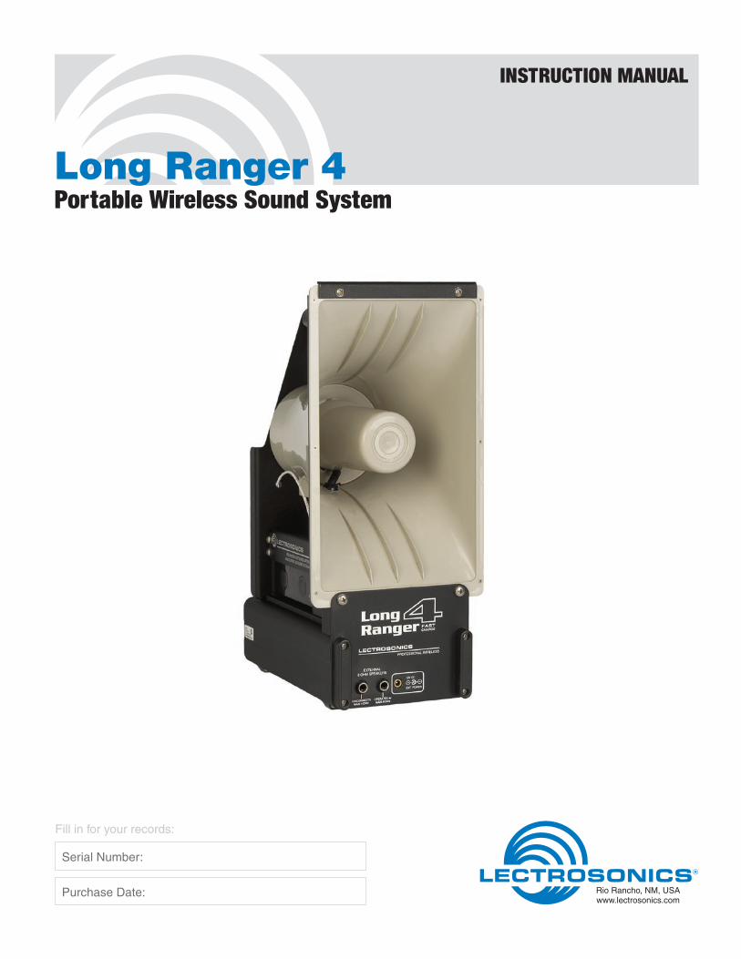
Long Ranger 4Portable Wireless Sound System
INSTRUCTION MANUAL
Rio Rancho, NM, USAwww.lectrosonics.com
Fill in for your records:
Serial Number:
Purchase Date:
Long Ranger 4
LECTROSONICS, INC.2
ContentsGeneral Technical Description ..............................................................................................................................................................3Rechargeable Batteries and External Power Sources ........................................................................................................................3Controls and Functions .........................................................................................................................................................................4
Control Panel ........................................................................................................................................................................................4Front Panel ............................................................................................................................................................................................5
System Setup ..........................................................................................................................................................................................6Initial Equipment Adjustments ..............................................................................................................................................................6M175 Controls and Functions ...............................................................................................................................................................8
MIC JACK .............................................................................................................................................................................................8POWER ON/OFF ..................................................................................................................................................................................8BATTERY INDICATOR LAMP ...............................................................................................................................................................8MIC LEVEL ADJUST ............................................................................................................................................................................8AUDIO SWITCH ....................................................................................................................................................................................8
M175 Battery Replacement ....................................................................................................................................................................8H187 Controls and Functions ................................................................................................................................................................8
POWER ON/OFF ..................................................................................................................................................................................9BATTERY POWER LED .......................................................................................................................................................................9LEVEL CONTROL ................................................................................................................................................................................9
H187 Battery Replacement ..................................................................................................................................................................10Using Additional Speakers ..................................................................................................................................................................10Adding a Second Wireless Channel to your Long Ranger ...............................................................................................................11Initial Adjustments to the Add-On Receiver System .........................................................................................................................12Special Note to Dual Channel Users ...................................................................................................................................................12Multiple Long Ranger Systems ...........................................................................................................................................................13Microphone Choices ............................................................................................................................................................................14Accessories and Replacement Parts ..................................................................................................................................................15Troubleshooting ....................................................................................................................................................................................16Symptom Possible Cause .......................................................................................................................................................................16Service and Repair ...............................................................................................................................................................................17Returning Units for Repair ......................................................................................................................................................................17

Portable Wireless Sound System
Rio Rancho, NM 3
The built-in battery pack in the Long Ranger is charged by plugging the DCR15/2AU charger into the jack labeled DCR15/2AU CHARGER on the control panel. Connect the charger into a standard 110 or 220 Volt AC outlet. (The DCR15/2AU charger can be operated from 110/220V, 50/60Hz.) The green lamp beneath the jack will light as long as the batteries are charging. When the batteries are almost completely charged the green charg ing light will go out. You may leave the charger plugged in after the green light has gone out with no danger of damage to the system. In fact, we recom-mend charging the system whenever it is not in use, then the system will always be “ready to go.”
The DCR15/2AU charger can charge the batteries in as little as 2 1/2 hours. If the unit is completely run down, it may require as much as 6 hours to fully charge the bat-teries. Leave the charger plugged in at least until the green lamp below the CHARGER jack goes out.
(NOTE: In the case of severely discharged batteries (this can happen if the Long Ranger has been left on constantly for several months), it may be necessary to charge the unit for a much longer time. Up to 10 days charge time is not uncommon in these circumstances.)
Rechargeable Batteries and External Power Sources
The standard Long Ranger Portable Wireless Sound System consists of a combination wireless receiver/am-plifier/speaker with a rechargeable battery pack, a belt-pack or plug-on transmitter and a microphone. Optional microphones, extension speakers and add-on equip-ment for a second wireless channel are available.
The Long Ranger features a VHF wireless microphone system with a transmitter-to-receiver operating range of up to 750 feet. The receiver is designed for high selec-tivity to prevent interference from other transmitted radio signals. The system is designed and constructed for rigorous portable use with the antenna integrated into the horn speaker to eliminate damage.
General Technical DescriptionThe Long Ranger will operate from 8 to 12 hours from the “on-board” rechargeable battery pack before recharging is necessary. The actual operating time is dependent upon the type of usage... intermittent or con-tinuous. The unit can also be operated from an external 12 Volt DC source or an AC wall outlet.
The amplifier produces 33 Watts, RMS, into the 8 Ohm horn speaker. The sound output will cover an area the size of a football field under average outdoor conditions. Several Long Rangers can be easily connected togeth-er to provide even greater area coverage.
The DCR15/2A charger is capable of charging the bat-teries and running the Long Ranger in normal operation at the same time. The time required to fully recharge that batteries will be longer if the unit is being used while charging the battery pack.
CAUTION : USE ONLY THE SUPPLIED DCR15/2A CHARGER. DO NOT USE THE OLDER CH40 CHARGER IN THE NEW LONG RANGER 4. THE CH40 WILL NOT CHARGE THE BATTERIES IN THE LONG RANGER 4 AND WILL BE DAMAGED IF USED.
The Long Ranger can be operated from an external 12 Volt DC source such as an automobile battery or, most commonly, from the cigarette lighter receptacle in your vehicle. To use an external power source it must be connected into the 12V DC POWER INPUT jack on the Long Ranger front panel.
CAUTION: Make sure you comply with the polarity markings on the jack. The correct plug for making the co nnection is a Radio Shack 274-1567 size K coaxial DC power plug. Radio Shack also stocks cigarette lighter plugs (with built-in fuse) and cords to construct a suitable assembly

Long Ranger 4
LECTROSONICS, INC.4
Controls and FunctionsControl Panel
Wireless Microphone VolumeTurns unit power on and off and also functions as the volume control for the internal wireless receiver.
POWER A red LED that lights when unit power is on.
RF A green LED that lights when the companion transmit-ter is turned on and there is sufficient signal for good system operation. Internal circuits monitor both signal level and interference levels and decide if the transmit-ted signal is strong and “clean” enough for satisfactory operation. If not, the green RF LED will go out and the receiver will mute the audio (“squelch”), turning off the sound output. This action is automatic and requires no user adjustment.
Mod Level The red and green MOD LEVEL LEDs continuously in-dicate the modulation level (audio level) of the received signal from the transmitter and are used when making initial adjustments to the transmitter.
MIC This connector is a standard 1/4” phone jack and is used for plugging in the cord from a low impedance dynamic microphone.
Line This mini jack is used for connecting high level, high im-pedance outputs from tape decks or other amplifiers. It also may be used for connecting the “earphone” output from portable cassette players.
Auxiliary Input VolumeAdjusts the volume of the MIC and LINE inputs.
Aux In/OutAn RCA phono jack that functions both as a line level input and line level output. This “omnibus” jack is primarily used for interconnecting several Long Rang-ers together for simultaneous operation. This jack can also be used with a tape deck to either record from or play back into the Long Ranger. When used with a tape deck or other audio source, the sound output level must be controlled by the volume control on the tape deck since there is no volume control on the Long Ranger for the AUX IN/OUT jack. When an external device is con-nected to this jack, the loudness of the Long Ranger will usually be reduced.
DCR15/2AU ChargerA special jack used for connecting the charger when charging the battery pack. The green LED located under the jack lights when the batteries are charging. This LED automatically goes out when the batteries are almost fully charged.
12V DC OutputA special jack used to supply power to the Add-On receiver when that option is installed.

Portable Wireless Sound System
Rio Rancho, NM 5
12V DC
EXT POWER
Figure 1 - Long Ranger 4 Control Panel
Figure 2 - Long Ranger 4 Front Panel
12V DC Ext PowerA special jack used to connect an external 12 Volt DC source to the unit to substitute for the “on-board” bat-tery pack. It is most commonly used for connecting the Long Ranger to a vehicle cigarette lighter or 12V DC auxiliary receptacle. When an external power source is connected to this jack, the on-board battery pack is automatically disconnected.
CAUTION: Make sure you comply with the polarity markings on the jack. The correct plug for making the connection is a Radio Shack 274-1567 size K coaxial DC power plug. Radio Shack also stocks cigarette lighter plugs (with built-in fuse) and cords to construct a suitable assembly
External 8 Ohm SpeakersTwo jacks which are used to connect external 8 ohm loudspeakers such as the Lectrosonics H300 re-entrant horn. This jack can also be used to power other brands of loudspeakers, but be sure that the speaker has a rated impedance of 8 ohms. The left-hand jack discon-nects the built-in horn when the plug is inserted. The right-hand jack will operate the internal horn along with the external speaker. The efficiency of different makes and models of speakers varies significantly. Even though two different speakers are both rated at 8 ohms, their loudness could be quite a bit different. The other specification to compare when considering the use of another speaker is the efficiency rating. The horn built into the Long Ranger is rated at 107 dB SPL (sound pressure level) at one meter with a one watt input. Check this specification on the speaker you are consid-ering. A speaker with a lower “dB’ number will not be as loud as the horn built into the Long Ranger.
Front Panel

Long Ranger 4
LECTROSONICS, INC.6
This section covers the initial adjustments to the transmitter and Long Ranger that must be made before the system is placed into operation. The step-by-step procedures are listed in the order in which they should be performed:
1) Turn Long Ranger power on - The POWER lamp lights.
2) Rotate both volume controls counter-clockwise to their minimum settings.
3) Position yourself behind the Long Ranger so that the sound from the speaker will be directed away from the microphone.
4) Plug your microphone into the transmitter. Make sure the connector is screwed in snugly.
5) Turn the transmitter power on and verify that the red lamp on it lights. If the lamp is very dim or does not light, replace the battery.
6) Observe that the green RF lamp on the Long Rang-er control panel is lighted. This verifies that the unit is receiving a usable signal from the transmitter.
Initial Equipment Adjustments
This section includes some basic rules that will ensure trouble-free operation of your Long Ranger system:
1) Make sure the transmitter battery is good or new.
2) Charge up the battery pack in the Long Ranger fully before you use the system. Charge until the green charging lamp underneath the CHARGER jack on the Long Ranger control panel goes out.
3) Set up the system so that the Long Ranger is as far from large metal surfaces as possible. Metal sur-faces under the unit (such as pickup truck cabs or a car top) are generally no problem but large metal surfaces alongside the Long Ranger may interfere with wireless reception.
4) If you have more than one transmitter on the same frequency, turn on only one transmitter at a time. You cannot use two transmitters at the same time with a single Long Ranger. You will need to “al-ternate” back and forth between the transmitters. Failure to do so will result in an obnoxious whining sound from the system, and the audio will probably not be understandable. “Add-on” wireless mic sys-tems are available separately to permit operation of two transmitters simultaneously through a single Long Ranger.
System Setup5) Use the minimum volume that will enable everyone
to hear. It doesn’t have to be loud to be heard.
6) Always turn the power off before connecting or disconnecting external speakers.
7) The Long Ranger should be elevated for best coverage. The unit should ideally be at least 2 feet higher than the audience. For example, with an audience standing on flat ground, the number of people that can hear clearly will double if you raise the unit from 5 feet above the ground to 7 feet above the ground.
8) During actual operation the Long Ranger should be located at least 20 feet away from the person using the microphone and aimed so that the sound from the speaker is directed toward the audience and away from the microphone. This will reduce feedback problems. Feedback is a squealing sound coming from the speaker when the volume is too high or the microphone is too close to the Long Ranger. Feedback is generally much more of a problem when using lavalier (lapel) type micro-phones. The headset models are recommended for use with the Long Ranger system since they place the microphone pickup much closer to your mouth, which increases the volume of the Long Ranger before feedback occurs.
7) Position the microphone on yourself (or other user) in the location it will be during actual operation.
If you are using the single-band or dual-band headset microphone, turn the white knob on the headset fully clockwise (maximum). The HM162 over-ear microphone should be positioned so that the pickup element is just to the left of the mouth, so that breath pops do not strike the capsule. Lava-lier microphones should be positioned high on the chest or collar, as close to the mouth as possible to minimize the possibility of feedback. A handheld microphone with the H175DC plug-on transmitter should be kept at a consistent distance from the mouth during setup and use.
8) A small screwdriver is supplied with belt-back trans-mitters to adjust the audio gain of the transmitter to match your microphone and your voice. The plug-on transmitter has a small knob for adjusting gain. The adjustment is made while observing the MOD LEVEL lamps on the Long Ranger control panel:
a) Speak at the voice level you will be using during actual operation.

Portable Wireless Sound System
Rio Rancho, NM 7
b) While speaking, adjust the transmitter gain until the green MOD LEVEL lamp on the Long Ranger control panel is lighted or flickers and the red MOD LEVEL lamp blinks on the loudest words. Raise and lower your voice while observing the lamps. The red lamp should blink occasionally.
9) Now adjust the WIRELESS MICROPHONE VOL-UME control on the control panel to a level where everyone can hear. You will probably have to do this in several steps. If you attempt to adjust the volume yourself while standing and just behind the unit, you will likely have a “feedback” problem. It is convenient to have another person adjust the volume while you transmit from a position 20 feet or more behind the unit.
Figure 3 - Transmitter Gain Adjustment GreenLED
RedLED
REMEMBER — the transmitter gain control is used only to adjust for proper MOD LEVEL lamp indications. DO NOT use it to adjust the output volume of the Long Ranger speaker. Different voices and different micro-phones will usually require readjustment of the transmit-ter gain control, so check the adjustment frequently. If several different people will be using the system and there is not time to make the adjustment for each indi-vidual, adjust it for the loudest voice.
While speaking, adjust the transmitter as you observe the LEDs on the receiver.

Long Ranger 4
LECTROSONICS, INC.8
H187 Controls and FunctionsThe H187 may be used with a wide variety of micro-phones. The 3-pin XLR type connector on the H175DC allows the transmitter to be used with any dynamic microphone, as well as many two wire positive bias lavaliere systems (such as those systems supplied by Lectrosonics.)
MIC JACKThe MIC JACK is a locking micro jack that supplies “phantom power” for electret microphones such as the Lectrosonics M119, M140 Lavaliere and the HM142V, HM152V and HM162 headset models. Insert the micro-phone cord plug into the jack and rotate it clockwise to lock it. It is important that the plug be securely locked, since the microphone cord serves as the antenna for the transmitter.
POWER ON/OFFThe POWER ON/OFF switch turns the power on and off. The switch should be left in the OFF position when the transmitter is not in use. When the switch is in the ON position, the battery will be drained even though the transmitter is not being used.
BATTERY INDICATOR LAMPThe BATTERY INDICATOR LAMP will light when the transmitter is turned on and will stay lit as long as the battery is good. As the battery voltage drops, the lamp will grow dim and finally go out.
MIC LEVEL ADJUSTThe MIC LEVEL adjust is a recessed screwdriver adjustment used to match the gain of the transmitter to different microphones, individual voices or other audio inputs such as tape deck outputs.
AUDIO SWITCHThe AUDIO SWITCH (M175-LS only) is a toggle type on-off switch used to shut off the audio signal without shutting off the RF carrier of the transmitter.
(Note: The M175DC, Digital Code Squelch version is operationally identical to the standard M175.)
The battery you use in the M175 Series transmitter should be a 9 Volt lithium or alkaline, available almost everywhere. A lithium 9 Volt battery will provide the best performance with over 30 hours of operation. An alkaline battery will provide up to 15 hours of operation, and carbon zinc batteries, even if marked “heavy duty”
M175 Controls and Functionswill only provide about 4 hours of operation. Recharge-able batteries made to look like 9 Volt batteries typically only produce 7.2 Volts at full charge, which will only operate the transmitter for an hour or less. Make sure your batteries are marked “alkaline.” Short battery life is almost always caused by weak batteries or batteries of the wrong type.
The BATTERY LAMP will light when the transmitter is turned on and will stay lit as long as the battery is good. As the battery voltage drops, the lamp will grow dim and finally go out. Even after the lamp goes out, there may still be up to an hour or more of operating time remain-ing. When the battery voltage is too low for proper transmitter operation, the sound from the wireless system may be distorted, intermittent or totally absent. When the transmitter is first turned on, the lamp may light for a short while even with a bad battery. It is good practice to check the brightness of the lamp after the transmitter has been on for several minutes and to note the brightness occasionally during use.
To replace the battery, open the bottom battery door cover with your thumb, rotate the door until it is perpen-dicular with the case and allow the battery to fall out of the compartment into your hand. It is difficult to install the battery backwards. Observe the large and small holes in the battery contact pad before inserting a new battery. Insert the contact end of the battery first, mak-ing sure the contacts are aligned with the holes in the contact pad, and then swing the door closed. You will feel it snap into place when it is fully closed.
M175 Battery Replacement

Portable Wireless Sound System
Rio Rancho, NM 9
(Note: The H187, Digital Code Squelch version is operationally identical to the standard H175.)
1) Turn on the receiver and adjust the Long Ranger volume to minimum.
2) Turn on the transmitter. The RF LED on the receiv-er should come on.
3) Hold the microphone as you will when you will be using it.
4) While speaking, adjust the transmitter gain until the green MOD LEVEL lamp on the Long Ranger control panel is lighted or flickers and the red MOD LEVEL lamp blinks on the loudest words. Raise and lower your voice while observing the lamps. The red lamp should blink occasionally.
Occasional lighting of the LIMIT LED (about 10-15% of the time) indicates proper operation and optimum signal-to-noise ratio.
Even when the transmitter is limiting, little distortion is produced because of the high linearity of the gain con-trol circuit in the H187.
5) Adjust the Long Ranger volume level as necessary.
NOTES: The LEVEL control on the transmitter should not be used to control the volume of your sound system. This should be done using the level control on the Long Ranger.
If the mic level is too high - the Red LED on the Long Ranger will light frequently or stay on. This condition may cause distortion. If the mic level is too low — neither LED will light, or the Red LED will light dimly. This condition will cause hiss and noise. You may experience severe reduction in apparent range if the transmitter gain is too low. It may sound as if you are getting dropouts. What is actu-ally happening is that you are hitting your noise floor because the S/N ratio has been reduced by the low modulation. The input limiter operates over a full 30dB range regard-less of the gain control setting. The Red LED should flicker occasionally during operation
1. Install the Microphone onto the transmitter.
2. Press the mic onto the XLR connector until you hear a “click.” The click indicates the mic has locked into place.
3. Pull on mic to ensure that it is secure.
4. Tighten the collar by turning it counter-clock wise.
TO ATTACHTO REMOVE
Hold the transmitter case with the microphone pointed upward. Rotate the collar in the direction shown.
Pull on mic to ensure it is locked.
Press firmly, listen for click. Depress collar fully.
Click!
TO ATTACHTO REMOVE
Hold the transmitter case with the microphone pointed upward. Rotate the collar in the direction shown.
Pull on mic to ensure it is locked.
Press firmly, listen for click. Depress collar fully.
Click!
POWER ON/OFFTurns the battery power on and off.
BATTERY POWER LEDGlows brightly when battery is good. A weak or dim power LED means that the battery is weak, and has about an hour of operation left. If the LED fails to light, the battery should be replaced. The POWER LED is connected to a precision battery test circuit that continu-ously monitors battery voltage. The LED is at full bright-ness with a new 9 Volt alkaline. As the battery voltage drops during use, the LED brightness will also de-crease. After 12 to 15 hours the battery voltage will be about 7 Volts. The LED will be completely extinguished. Since the internal circuits are all tightly regulated and the RF output stage has a separate discrete regulator, the transmitter will continue to operate to a battery volt-age of 6.5 Volts. From 6.5 Volts to 6 Volts, the transmit-ter will still operate, but with degraded performance. Please note that a weak battery will sometimes light the POWER LED immediately after turn on, but soon will discharge to the point where the LED will extinguish.
The combination of an accurate battery condition indi-cator and regulation of all internal circuits guarantees much longer battery life, as well as consistent perfor-mance over the life of the battery.
LEVEL CONTROLUsed to adjust the audio input volume for the proper modulation level. Rotate knob until the LEVEL LED on the receiver flickers when there is an input signal. The LIMIT LED on the receiver should light occasionally.
Gain adjustment knob

Long Ranger 4
LECTROSONICS, INC.10
CAUTION! ALWAYS TURN THE LONG RANGER POWER OFF BEFORE PLUGGING IN OR UNPLUGGING EXTERNAL SPEAKERS
In some cases, the proper coverage of an audience re-quires a second speaker. The optional H300 is identical to the Long Ranger speaker and can be used to spread the sound over a broader area.
The output jacks for external speakers are located on the Long Ranger front panel. The left and right jacks operate differently. The right jack does not discon-nect the built-in speaker when a plug is inserted into it. This means that the built-in speaker and the external speaker will both operate together. The left output jack disconnects the built-in speaker and powers only the external speaker. Internal circuits and switching net-works keep track of the number of speakers hooked up and select the amplifier impedance so that the full power of the amplifier is always available. It is impor-tant that you use only an 8 Ohm speaker in these jacks. If you are not using Lectrosonics extension speakers, check the speaker for the proper rating before connect-ing to the Long Ranger.
The efficiency of different makes and models of speak-ers varies significantly. Even though two different
Using Additional Speakers
The battery you use in the H187 Series transmitter should be a 9 Volt lithium or alkaline, available almost everywhere. A lithium 9 Volt battery will provide the best performance with over 30 hours of operation. An alkaline battery will provide up to 15 hours of operation, and carbon zinc batteries, even if marked “heavy duty” will only provide about 4 hours of operation. Recharge-able batteries made to look like 9 Volt batteries typically only produce 7.2 Volts at full charge, which will only operate the transmitter for an hour or less. Make sure your batteries are marked “alkaline.” Short battery life is almost always caused by weak batteries or batteries of the wrong type.
To open the battery compartment, press outward on the cover door in the direction of the arrow as shown in the drawing. Only slight, sliding pressure is needed to open and close the battery door.
H187 Battery ReplacementSwing the door open and take note of the polarity marked inside showing the location of the positive (+) and negative (-) terminals. Insert the battery and close the cover by pressing in and across, reversing the opening procedure. Note that the battery door will NOT close if the battery is inserted incorrectly, since the terminals will hit a protective polarity barrier.
speakers are both rated at 8 ohms, their loudness could be quite a bit different. The other specification to compare when considering the use of another speaker is the efficiency rating. The horn built into the Long Ranger is rated at 107 dB SPL (sound pressure level) at one meter with a one watt input. Check this specifi-cation on the speaker you are considering. A speaker with a lower “dB’ number will not be as loud as the horn built into the Long Ranger.
The H300 speaker is typically used in conjunction with the built-in speaker to increase the sound coverage area. This is done by plugging the H300 into the right speaker jack, so that both speakers will work together. In a large area, such as a football field, try to arrange the speakers so that the listeners are not in the direct sound field of both speakers. If a listener can hear two speakers located at different distances, a distracting “echo effect” occurs. Put the speakers close to one another in a central location and aim them in opposite directions to broaden the coverage pattern.
When using two external speakers simultaneously, the built-in speaker will be automatically disconnected to prevent overload of the amplifier since a plug has been inserted into the left-hand jack.

Portable Wireless Sound System
Rio Rancho, NM 11
Figure 4 - Add-on Receiver Antenna Connections
Adding a Second Wireless Channel to your Long RangerA very popular feature of the Long Ranger is the ability to add a second wireless channel to an existing system in the field. The Lectrosonics Add-On Receiver system was expressly designed for that purpose. The standard system consists of an Add-On receiver, a transmitter and a microphone.
The Add-On receiver is supplied with velcro attach-ing strips and is equipped with the necessary cabling for making the connections to the Long Ranger. The receiver is installed on the Long Ranger by performing the following steps as shown in Figure 4:
1) The antenna cable for the Add-On is packed together with screws, lock washers and the velcro strips. The antenna cable is terminated with two ring lugs. Feed the lug end of this cable through the hole in the Long Ranger rear panel upright. Dress the cable along the top of the battery pack along with the speaker wires as shown in Figure 4.
2) Remove and discard the two black Phillips head screws from the bottom of the antenna strip on the right-hand side of the speaker and from the speaker
mounting block. Using the supplied bright screws and lock washers, connect the shield ring lug (the black wire) to the speaker mounting block. Connect the center conductor ring lug (the clear/white wire) to the antenna. Tighten both screws securely.
3) The Add-On receiver is to be mounted on the Long Ranger upright with velcro. The receiver should be positioned, control panel up, between the horn mounting screw and the screw which secures the battery pack to the upright. Remove the paper backing from one side of the velcro and affix it to the back of the receiver. Remove the remaining paper backing and affix the receiver to the upright.
4) Route the antenna cable through the hole in the rear upright panel, above the battery pack so that the black and white wires reach the speaker mount-ing block. Connect the remaining two cables to the 12V DC OUTPUT jack and the LINE input jack on the control panel.
Antenna Cable
Feed through hole
Connect the center conductor wire (clear/white wire) to the antenna. Connect shield ring wire to chassis ground.
Chassis ground
Shield wire Center
conductor
Figure 4
Long Ranger 4
LECTROSONICS, INC.12
If you are only using one of the two wireless systems, it is best to use the wireless system built into the Long Ranger and leave the Add-On receiver turned off. This will prevent unwanted noise, hiss or static that could occur in the unused receiver from entering the Long Ranger.
Special Note to Dual Channel Users
1) Set up the Long Ranger system according to the Initial Equipment Adjustments on page 6.
2) Leave the Long Ranger power turned on. Set both volume controls on the Long Ranger control panel to minimum.
3) Turn the Add-On receiver power switch to “ON.” Check to see that the power lamp comes on.
4) Plug the microphone into the transmitter that is on the same frequency as the Add-On receiver. The plug on the microphone is a twist-lock connector. Make sure there is a good connection. If you are using the head set microphone, turn the white level control knob on the headset fully clockwise (maxi-mum).
5) Install the 9 Volt battery into the transmitter, turn the transmitter on and make sure the red LED on the transmitter glows brightly.
6) Check to see that the green “RF” LED on the Add-On receiver glows steadily. This verifies that the receiver is picking up a good radio signal from the transmitter.
Initial Adjustments to the Add-On Receiver System7) This is the most important step in the set up
procedure. Place the microphone in the exact po-sition where you will be using it. Speak at the same voice level that you will use during actual operation. While you speak, use the supplied screwdriver to adjust the gain control on the transmitter side panel (see pages 5 & 7) while you observe the MODULA-TION LEDs on the Add-On receiver front panel. The green LEVEL lamp should flicker or stay lit as you speak. The red LIMIT lamp should blink only on louder words.
8) Adjust the AUXILIARY INPUT VOLUME control on the Long Ranger control panel for the necessary loudness. If the transmitter gain controls have been correctly set on both the Longer Ranger 4 and the Add-On system, both volume control knobs on the Longer Ranger 4 panel will be in about the same position for equal loudness on both systems. It is not unusual, however, that one of the volume controls may need to be set higher or lower than the other one in normal use. Adjust the controls separately for adequate sound levels for each mi-crophone.
If it is necessary to use the Add-On receiver by itself, turn the WIRELESS MICROPHONE VOLUME control knob on the Long Ranger control panel to minimum. Then set the AUXILIARY INPUT VOLUME for the nec-essary loudness of the Add-On system.

Portable Wireless Sound System
Rio Rancho, NM 13
OFF
RF
12V DCOUTPUT
CHARGE UNTILLAMP GOES OUT
DCR15/2AUCHARGER
POWER
AUX IN/OUT
MIC LINE
WIRELESSMICROPHONE
VOLUME
AUXILIARYINPUT
VOLUME
MODLEVEL
USEONLY
OFF
RF
12V DCOUTPUT
CHARGE UNTILLAMP GOES OUT
DCR15/2AUCHARGER
POWER
AUX IN/OUT
MIC LINE
WIRELESSMICROPHONE
VOLUME
AUXILIARYINPUT
VOLUME
MODLEVEL
USEONLY
Figure 5 - Connecting Two Long Ranger Systems
Multiple Long Ranger SystemsA unique use of the AUX IN/OUT jack is for connecting two Long Ranger systems together for simultaneous use. When connected in this manner, they will operate like a single system. It is best to use two different Long Ranger units that operate on different frequencies. Any input on either Long Ranger will appear at both speak-ers. If the Long Ranger systems are on the same fre-quency, only one transmitter can be used at any given moment.
Second channel (add-on) wireless systems on either (or both) Long Ranger systems will work fine, as long as they are all on different frequencies. Each wireless microphone will have its own volume control. The built-in wireless in each Long Ranger will be controlled by the left-hand knob on the matching unit. The volume of each add-on wireless system will be controlled by the right-hand knob on the matching unit. All sound from all wireless microphones will appear on all loudspeakers, both built-in or external.
Connect the Long Ranger systems together with a stan-dard RCA (phono) patch cord, male plug to male plug. It is best to use cords 10 to 12 ft. in length (or less) to minimize noise that can occur with long cables.
If any of the Long Rangers or add-on wireless system are on the same frequency, only one transmitter can be used at a time on that frequency. REMEMBER that if two transmitters on the same frequency are turned on at the same time, the receiver will not receive either of them properly. You will need to “alternate” the use of the transmitters.
The INITIAL EQUIPMENT ADJUSTMENTS (see page 6) should be performed on each system individually before the AUX IN/OUT interconnection is made. After the units are connected together, adjust the volume on each Long Ranger for the loudness level needed.

Long Ranger 4
LECTROSONICS, INC.14
SpecificationsOperating frequency: 169 to 186 MHzAudio power output: 33 Watts, RMS, into 8 OhmsDistortion: less than 1%Amplifier freq. response: 100 Hz to 15 kHz; +0, -3 dB (Omnibus jack input to external speaker jack output.)Overall freq. response: 200 Hz to 3 kHz; +0/-3dB (Wireless input tohorn output.)Max. audio output (SPL): Over 120 dB at 3 feet
M119 - This is a very small, omni-directional mic used only as a lavaliere (“lapel”) microphone. It may be prone to feedback since it is usually placed so far away from the users mouth; however it has a very flat re-sponse and excellent tone quality. The M119 generally works best with the Long Ranger and an ES300 column speaker indoors at a lower volume setting. As is true of most omni-directional type microphones, the M119 is very free from wind noise and clothing “rattle”.
M140 - A cardioid (directional) microphone for lavaliere (“lapel”) use. Due to the directional pickup pattern, this model will generally provide more gain (loudness) before feedback than the M119 omni-directional model. The M140 has a “brighter” sound than the M119 (the treble is boosted). This crisper sound normally im-proves the clarity that is sometimes lost with lavaliere type microphones. The M140 is subject to wind noise and generally works best indoors, however it is supplied with a foam windscreen which helps to prevent noise caused by wind.
HM142V - This single-band headset microphone is nor-mally worn on the head, but can also be worn around the neck for hands-free operation. It provides maximum gain before feedback since the micro phone is very close to the user’s mouth. The built-in volume control helps control feedback in difficult environments, such as when the user must be close to the Long Ranger. Worn on the head, the micro phone will remain at a constant distance from the user’s mouth, which keeps the vol-ume of the sound system constant as your head moves.
Microphone ChoicesHM152V - A double-band headset microphone intended to be worn on the head. The pickup element and tonal characteristics are the same as the single-band HM142V, but it is more securely mounted and in most cases, more comfortable, due to the fully adjustable dual headband. The same volume control is provided to help control feedback.
HM162 - A “over the ears” noise cancelling microphone that uses a dual-element design to minimize feedback when the microphone is close to the speaker.
Other brands of microphones may be used, provided they are the correct type, with an appropriate connec-tor. Consult the factory or your dealer if you are not sure. A mis-matched microphone will generally cause background noise (hiss) or feedback problems, or may not work at all.
FM deviation: ±15kHzWireless operating range: Up to 750 feetRF signal-to-noise ratio: 96dB, A weightedSpeaker: 6” x 12” re-entrant hornWeight: 16 lbs.Dimensions: 15” high, 6 3/4” wide, 9 3/4” deep
Specifications subject to change without notice.
Portable Wireless Sound System
Rio Rancho, NM 15
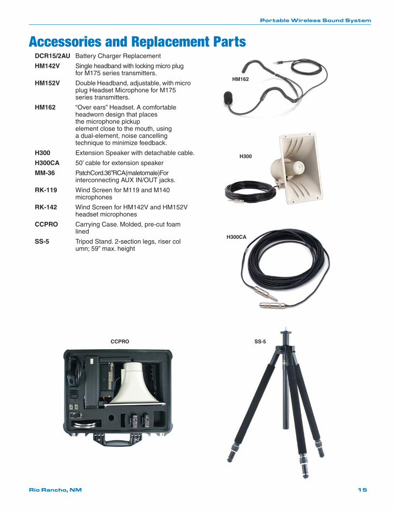
Accessories and Replacement PartsDCR15/2AU Battery Charger Replacement
HM142V Single headband with locking micro plug for M175 series transmitters.
HM152V Double Headband, adjustable, with micro plug Headset Microphone for M175 series transmitters.
HM162 “Over ears” Headset. A comfortable headworn design that places the microphone pickup element close to the mouth, using a dual-element, noise cancelling technique to minimize feedback.
H300 Extension Speaker with detachable cable.
H300CA 50’ cable for extension speaker
MM-36 Patch Cord. 36” RCA (male to male) For interconnecting AUX IN/OUT jacks.
RK-119 Wind Screen for M119 and M140 microphones
RK-142 Wind Screen for HM142V and HM152V headset microphones
CCPRO Carrying Case. Molded, pre-cut foam lined
SS-5 Tripod Stand. 2-section legs, riser col umn; 59” max. height
HM162
H300
H300CA
SS-5CCPRO

Long Ranger 4
LECTROSONICS, INC.16
Symptom Possible Cause
Long Ranger red POWER lamp not on or dim
1) WIRELESS MICROPHONE VOLUME control in OFF position
2) Batteries completely discharged
3) Battery terminals disconnected or loose
Long Ranger green RF lamp not on
1) Transmitter not on
2) Dead battery in transmitter
3) Transmitter and receiver not on same frequency
Long Ranger red POWER lamp and green RF lamp on, but no sound
A) MOD LEVEL lamps dark 1) Transmitter is not getting an audio signal. Defective mic or cable.
2) Transmitter gain control set much too low
B) MOD LEVEL lamps indicating 1) WIRELESS MICROPHONE VOLUME control normal turned completely down
2) Defective horn or speaker
System operation normal except for high hiss or hum level
A) Green MOD LEVEL lamp 1) Transmitter gain control set too low dark or barely flickers
2) Headset volume (white knob) turned down
B) MOD LEVEL lamps appear normal 1) Noisy microphone or mic cable? To verify, replace with known good microphone.
2) Hiss in device connected to Long Ranger? Turn off the device. If hiss stops, problem is in the device. If hiss remains, the prob lem is in the Long Ranger.
3) Hiss in the Long Ranger can be caused by poorly shielded computers, phone systems, older electronic organs, etc. Try turning off nearby suspect equipment.
System operation normal except for “feedback” and/or red MOD LEVEL lamp on or blinking frequently
1) Transmitter gain set too high.
2) Output level of device connected is too high
Weak, distorted sound. Power lamp flickers. “Motorboating” (rapid popping sound.) 1) Batteries very low. Recharge.
Troubleshooting

Portable Wireless Sound System
Rio Rancho, NM 17
Service and RepairIf your system malfunctions, you should attempt to correct or isolate the trouble before concluding that the equipment needs repair. Make sure you have followed the setup procedure and operating instructions. Check the interconnecting cables and then go through the Troubleshooting section in this manual.
We strongly recommend that you do not try to repair the equipment yourself and do not have the local repair shop at-tempt anything other than the simplest repair. If the repair is more complicated than a broken wire or loose connection, send the unit to the factory for repair and service. Don’t attempt to adjust any controls inside the units. Once set at the factory, the various controls and trimmers do not drift with age or vibration and never require readjustment. There are no adjustments inside that will make a malfunctioning unit start working.
LECTROSONICS’ Service Department is equipped and staffed to quickly repair your equipment. In warranty repairs are made at no charge in accordance with the terms of the warranty. Out-of-warranty repairs are charged at a modest flat rate plus parts and shipping. Since it takes almost as much time and effort to determine what is wrong as it does to make the repair, there is a charge for an exact quotation. We will be happy to quote approximate charges by phone for out-of-warranty repairs.
Returning Units for RepairFor timely service, please follow the steps below:
A. DO NOT return equipment to the factory for repair without first contacting us by email or by phone. We need to know the nature of the problem, the model number and the serial number of the equipment. We also need a phone number where you can be reached 8 A.M. to 4 P.M. (U.S. Mountain Standard Time).
B. After receiving your request, we will issue you a return authorization number (R.A.). This number will help speed your repair through our receiving and repair departments. The return authorization number must be clearly shown on the outside of the shipping container.
C. Pack the equipment carefully and ship to us, shipping costs prepaid. If necessary, we can provide you with the proper packing materials. UPS is usually the best way to ship the units. Heavy units should be “double-boxed” for safe transport.
D. We also strongly recommend that you insure the equipment, since we cannot be responsible for loss of or dam-age to equipment that you ship. Of course, we insure the equipment when we ship it back to you.
Lectrosonics USA:
Mailing address: Shipping address: Telephone: Lectrosonics, Inc. Lectrosonics, Inc. (505) 892-4501 PO Box 15900 581 Laser Rd. (800) 821-1121 Toll-free Rio Rancho, NM 87174 Rio Rancho, NM 87124 (505) 892-6243 Fax USA USA
Web: E-mail: www.lectrosonics.com [email protected]
Lectrosonics Canada:
Mailing Address: Telephone: E-mail: 49 Spadina Avenue, (416) 596-2202 Sales: [email protected] Suite 303A (877) 753-2876 Toll-free Service: [email protected] Toronto, Ontario M5V 2J1 (877-7LECTRO) (416) 596-6648 Fax

Long Ranger 4
LECTROSONICS, INC.18

Portable Wireless Sound System
Rio Rancho, NM 19

05 May 09
581 Laser Road NE • Rio Rancho, NM 87124 USA • www.lectrosonics.com(505) 892-4501 • (800) 821-1121 • fax (505) 892-6243 • [email protected]
LIMITED ONE YEAR WARRANTYThe equipment is warranted for one year from date of purchase against defects in materials or workmanship provided it was purchased from an authorized dealer. This warranty does not cover equipment which has been abused or damaged by careless handling or shipping. This warranty does not apply to used or demonstrator equipment.
Should any defect develop, Lectrosonics, Inc. will, at our option, repair or replace any defective parts without charge for either parts or labor. If Lectrosonics, Inc. cannot correct the defect in your equipment, it will be replaced at no charge with a similar new item. Lectrosonics, Inc. will pay for the cost of returning your equipment to you.
This warranty applies only to items returned to Lectrosonics, Inc. or an authorized dealer, shipping costs prepaid, within one year from the date of purchase.
This Limited Warranty is governed by the laws of the State of New Mexico. It states the entire liablility of Lectrosonics Inc. and the entire remedy of the purchaser for any breach of warranty as outlined above. NEITHER LECTROSONICS, INC. NOR ANYONE INVOLVED IN THE PRODUCTION OR DELIVERY OF THE EQUIPMENT SHALL BE LIABLE FOR ANY INDIRECT, SPECIAL, PUNITIVE, CONSEQUENTIAL, OR INCIDENTAL DAMAGES ARISING OUT OF THE USE OR INABILITY TO USE THIS EQUIPMENT EVEN IF LECTROSONICS, INC. HAS BEEN ADVISED OF THE POSSIBILITY OF SUCH DAMAGES. IN NO EVENT SHALL THE LIABILITY OF LECTROSONICS, INC. EXCEED THE PURCHASE PRICE OF ANY DEFECTIVE EQUIPMENT.
This warranty gives you specific legal rights. You may have additional legal rights which vary from state to state.