Embed Size (px)
Citation preview
Version 20/01 – State September 2020
Instruction manual and data sheet
Torque Sensor Series 3000

Copyright ©
NCTE AG® Torque Sensor Series 3000 Instruction Manual and Data Sheet.
This instruction manual is property of NCTE AG®,
D-82041 Oberhaching
Unauthorized duplication, even in part, is not permitted.
State: September 2020
Instruction manual
1 General ...................................................................................................................................................... 5
1.1 Customer service address .................................................................................................................. 5
1.2 Warranty ............................................................................................................................................ 5
1.3 Scope of delivery ............................................................................................................................... 5
1.4 Declaration of conformity ................................................................................................................. 6
2 Safety ......................................................................................................................................................... 7
2.1 Intended use ...................................................................................................................................... 7
2.2 Duration of use .................................................................................................................................. 7
2.3 Structural change............................................................................................................................... 7
2.4 Training of the operating personnel .................................................................................................. 7
2.5 Transport and handling ..................................................................................................................... 7
3 Torque Sensor Series 3000 ........................................................................................................................ 8
3.1 Short description ............................................................................................................................... 8
3.2 Assembly and disassembly ................................................................................................................ 8
3.3 Interface description ......................................................................................................................... 8
3.4 Starting up ......................................................................................................................................... 8
3.5 Operation during regular mode......................................................................................................... 9
3.6 Irregular operation, actions in case of failures .................................................................................. 9
3.7 Safety instructions ............................................................................................................................. 9
3.8 Shaft preservation ............................................................................................................................. 9
3.9 Service, maintenance and repair ....................................................................................................... 9
3.10 Disposal.............................................................................................................................................. 9

Data sheet
1 Key Facts .................................................................................................................................................. 10
2 Torque ranges .......................................................................................................................................... 10
3 Load characteristics ................................................................................................................................. 11
4 Technical characteristics .......................................................................................................................... 11
5 EMV Emission data .................................................................................................................................. 12
6 Dimensions .............................................................................................................................................. 13
7 Wiring diagram ........................................................................................................................................ 14
8 Sensor wiring ........................................................................................................................................... 14
9 Angle sensor ............................................................................................................................................ 14
10 Order options .......................................................................................................................................... 15
11 Accessories .............................................................................................................................................. 15
_______________________________________________________________________________________
_______________________________________________________________________________________ Page 5 of 16
Instruction manual .
1 General
Dear customers,
Thank you for your decision to buy our sensor products. You have chosen a high quality and extremely precise
torque measuring system.
This manual contains all the information necessary for you and the installation, operating and maintenance
personnel to use your measuring system under the intended conditions of use. It contains important
information to ensure proper and safe installation and operation.
For these reasons, the Instruction manual must always be available at the place of use of the torque
measuring system and always ready to hand.
We reserve the right to make changes in the course of product improvements. We try to maintain
compatibility with previous versions. All information without guarantee subject to technical changes.
For further questions we are of course also available after the purchase at any time.
Please use our contact address.
1.1 Customer service address
NCTE AG
Raiffeisenalle 3
D-82041 Oberhaching
Phone: +49 (0)89 665 619 0
Email: [email protected]
Web: https://ncte.com/
1.2 Warranty
The warranty period is 12 months from the date of delivery from the factory, provided that the product is
used in accordance with its intended purpose, in compliance with the maintenance and calibration
regulations and the General Terms and Conditions of Business.
You can find these, current instruction manuals and data sheets on: https://ncte.com/serienprodukte/
1.3 Scope of delivery
The torque sensor system consists of a calibrated sensor, signal acquisition / -processing integrated in the
housing, a 5 m long connection cable with plug (Binder plug no. 99-0426-10-08) and keystone (round shaft).
Enclosed you will find the corresponding calibration certificate and the warning notes.
_______________________________________________________________________________________
_______________________________________________________________________________________ Page 6 of 16
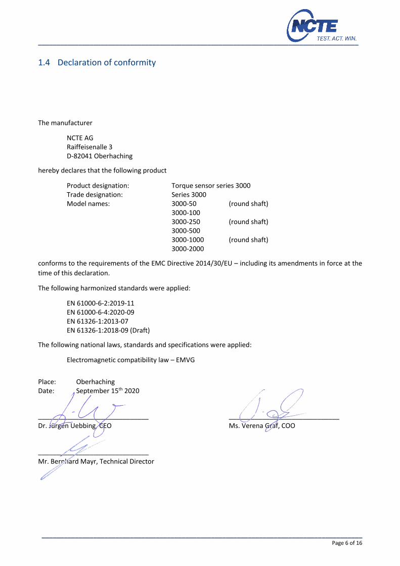
1.4 Declaration of conformity
The manufacturer
NCTE AG Raiffeisenalle 3 D-82041 Oberhaching
hereby declares that the following product
Product designation: Torque sensor series 3000 Trade designation: Series 3000 Model names: 3000-50 (round shaft) 3000-100 3000-250 (round shaft) 3000-500 3000-1000 (round shaft) 3000-2000
conforms to the requirements of the EMC Directive 2014/30/EU – including its amendments in force at the
time of this declaration.
The following harmonized standards were applied:
EN 61000-6-2:2019-11 EN 61000-6-4:2020-09 EN 61326-1:2013-07 EN 61326-1:2018-09 (Draft)
The following national laws, standards and specifications were applied:
Electromagnetic compatibility law – EMVG
Place: Oberhaching Date: September 15th 2020
______________________________ ______________________________
Dr. Jürgen Uebbing, CEO Ms. Verena Graf, COO
______________________________
Mr. Bernhard Mayr, Technical Director

_______________________________________________________________________________________
_______________________________________________________________________________________ Page 7 of 16
2 Safety
Please note the enclosed sheet on the warning notes.
2.1 Intended use
The sensors of the Series 3000 are designed exclusively for measuring torque and/or speed. The respective
load range can be taken from the data sheet and must not be exceeded.
Proper use also includes compliance with the commissioning, assembly, operating, ambient and maintenance
conditions specified by the manufacturer.
Any use beyond these is considered improper. The manufacturer is not liable for any damage resulting from
such use.
2.2 Duration of use
A factory recalibration should be executed annually. See corresponding label on the sensor.
2.3 Structural change
Unauthorized conversions or changes to the torque measuring system are prohibited for safety reasons and
lead to the immediate expiration of the warranty claims.
2.4 Training of the operating personnel
Assembly, commissioning and maintenance personnel must have read and understood the complete
operating instructions, especially Chapter “2 Safety". The operator is recommended to have this confirmed
in writing.
2.5 Transport and handling
During handling, storage and transport, make sure that the sensor is not exposed to strong magnetic or
electromagnetic fields (e.g. degaussing coils).
_______________________________________________________________________________________
_______________________________________________________________________________________ Page 8 of 16
3 Torque Sensor Series 3000
The Series 3000 serves the segment of very precise and reliable torque measurement technology.
3.1 Short description
The series is mainly used in laboratories, test fields and trials, in medical technology as well as in production
monitoring and quality assurance. With the Series 3000, torques can be measured statically as well as
dynamically in real time. The shaft is available as round and square. Each sensor can be configured
individually, so there is the option of an angle sensor. Analogue outputs 0-10V or 4-20mA are available as
signal outputs for the Series 3000. The sensor is supplied as a ready-to-connect unit including 5m long cable,
keystones (round shaft) and calibration certificate.
3.2 Assembly and disassembly
When mounting the sensor, make sure that the measuring shaft is exactly aligned with the connecting shafts
(corresponding couplings can be found in the accessories). It must then be possible to push the key adapters
/ square ends of the connection shafts onto the key adapter connections / square connections of the sensor
without any effort. No force must be exerted on the housing in the axial direction during fastening. The sensor
can be secured against rotation by means of the flat surface (optional sensor holder). The cable length must
not exceed 5m. Using a cable other than the one supplied by NCTE or an identical cable with a different cable
length may impair the function of the sensor system.
The disassembly may only be done without applying torque to the measuring shaft.
3.3 Interface description
Mechanical interfaces:
For power transmission, adapter connections are provided at both ends of the keystone round shafts.
In respect to square sensors, the shaft has square ends.
Electrical interface:
A socket for power supply and signal output is attached to the upper side of the housing.
(Pin assignment see Chapter “7 Wiring diagram")
3.4 Starting up
After mounting the sensor, the following must be observed:
Switch on power supply and check voltage value.
(Voltage peaks at the sensor must be avoided, devices must be checked accordingly before
connection to the sensor)
Connect the sensor to the power supply. (using the cable supplied)
Record the output signal of the sensor with high resistance. (e.g. A/D converter, oscilloscope,
PC measuring card)
Record output signal in mechanically unloaded state of the sensor.

_______________________________________________________________________________________
_______________________________________________________________________________________ Page 9 of 16
3.5 Operation during regular mode
Optimal measuring values are achieved when the sensor is used while maintaining the specific nominal
torque. If the permissible operating conditions are observed, the sensor operates trouble-free and
maintenance-free.
3.6 Irregular operation, actions in case of failures
If the sensor is mechanically overloaded (e.g. if the maximum permissible longitudinal force or torque limit
is exceeded or if there are strong vibrations), the sensor may be damaged and the signal output may be
distorted. In this case do not open the device. Contact NCTE AG directly.
3.7 Safety instructions
The following safety instructions should be followed for smooth operation:
Opening the sensor or even single screws is not allowed.
The shaft retaining rings on the shaft ends must not be loosened.
The fastening nut of the plug must not be loosened or tightened.
Only use power supplies safely disconnected from the mains voltage.
Regarding the electrical and mechanical load of the sensor, the specifications according to the
sensor-specific nameplate and the table in Chapter “4 Technical characteristics” must be observed.
The sensor is not to be used as support bearing. The existing fastening options serve exclusively to
secure the housing against twisting.
To protect your system, we recommend increasing the torque over several stages.
3.8 Shaft preservation
The shafts are protected on both sides with a film of anti-corrosion wax. We recommend to leave the
protection permanently. If technically necessary, remove the protective film with spirit/ethanol.
3.9 Service, maintenance and repair
As part of your test and measurement equipment management, we recommend regular inspection of your
test and measurement equipment. Please also observe the relevant standards and guidelines.
Maintenance plan by NCTE AG
Calibration: Every 12 months
Check the wiring, connectors and shaft: Every 12 months
Repairs and recalibrations can only be carried out by NCTE AG personnel.
3.10 Disposal
The device must be returned to NCTE AG, Raiffeisenallee 3, D-82041 Oberhaching for disposal.
_______________________________________________________________________________________
_______________________________________________________________________________________ Page 10 of 16
Data sheet .
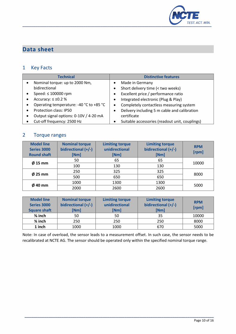
1 Key Facts
Technical Distinctive features
Nominal torque: up to 2000 Nm, bidirectional
Speed: ≤ 100000 rpm
Accuracy: ≤ ±0.2 %
Operating temperature: -40 °C to +85 °C
Protection class: IP50
Output signal options: 0-10V / 4-20 mA
Cut-off frequency: 2500 Hz
Made in Germany
Short delivery time (< two weeks)
Excellent price / performance ratio
Integrated electronic (Plug & Play)
Completely contactless measuring system
Delivery including 5 m cable and calibration certificate
Suitable accessories (readout unit, couplings)
2 Torque ranges
Model line Series 3000 Round shaft
Nominal torque bidirectional (+/-)
[Nm]
Limiting torque unidirectional
[Nm]
Limiting torque bidirectional (+/-)
[Nm]
RPM [rpm]
Ø 15 mm 50 65 65
10000 100 130 130
Ø 25 mm 250 325 325
8000 500 650 650
Ø 40 mm 1000 1300 1300
5000 2000 2600 2600
Model line Series 3000
Square shaft
Nominal torque bidirectional (+/-)
[Nm]
Limiting torque unidirectional
[Nm]
Limiting torque bidirectional (+/-)
[Nm]
RPM [rpm]
⅜ inch 50 50 35 10000
¾ inch 250 250 250 8000
1 inch 1000 1000 670 5000
Note: In case of overload, the sensor leads to a measurement offset. In such case, the sensor needs to be
recalibrated at NCTE AG. The sensor should be operated only within the specified nominal torque range.
_______________________________________________________________________________________
_______________________________________________________________________________________ Page 11 of 16
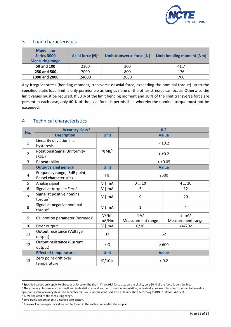
3 Load characteristics
Model line Series 3000
Measuring range Axial force [N]1 Limit transverse force [N] Limit bending moment [Nm]
50 and 100 2300 300 41.7
250 and 500 7000 800 176
1000 and 2000 24000 2000 700
Any irregular stress (bending moment, transverse or axial force, exceeding the nominal torque) up to the
specified static load limit is only permissible as long as none of the other stresses can occur. Otherwise the
limit values must be reduced. If 30 % of the limit bending moment and 30 % of the limit transverse force are
present in each case, only 40 % of the axial force is permissible, whereby the nominal torque must not be
exceeded.
4 Technical characteristics
1 Specified values only apply to direct axial force on the shaft. If the axial force acts on the circlip, only 50 % of the force is permissible. 2 The accuracy class means that the linearity deviation as well as the circulation modulation, individually, are each less than or equal to the value specified as the accuracy class. The accuracy class must not be confused with a classification according to DIN 51309 or EA-10/14. 3 % ME: Related to the measuring range. 4 Zero point can be set to 5 V using a tare button. 5 The exact sensor-specific values can be found in the calibration certificate supplied.
No. Accuracy class 2 0.2
Description Unit Value
1 Linearity deviation incl. hysteresis
%ME3
< ±0.2
2 Rotational Signal Uniformity (RSU)
< ±0.2
3 Repeatability < ±0.05
Output signal general Unit Value
4 Frequency range, -3dB point, Bessel characteristics
Hz 2500
5 Analog signal V | mA 0 … 10 4 … 20
6 Signal at torque = Zero4 V | mA 5 12
7 Signal at positive nominal torque5 V | mA 9 20
8 Signal at negative nominal torque5 V | mA 1 4
9 Calibration parameter (normed)5 V/Nm mA/Nm
4 V/ Measurement range
8 mA/ Measurement range
10 Error output V | mA 0/10 <4/20<
11 Output resistance (Voltage output)
Ω 62
12 Output resistance (Current output)
k Ω ≥ 600
Effect of temperature Unit Value
13 Zero point drift over temperature
%/10 K < 0.2
_______________________________________________________________________________________
_______________________________________________________________________________________ Page 12 of 16
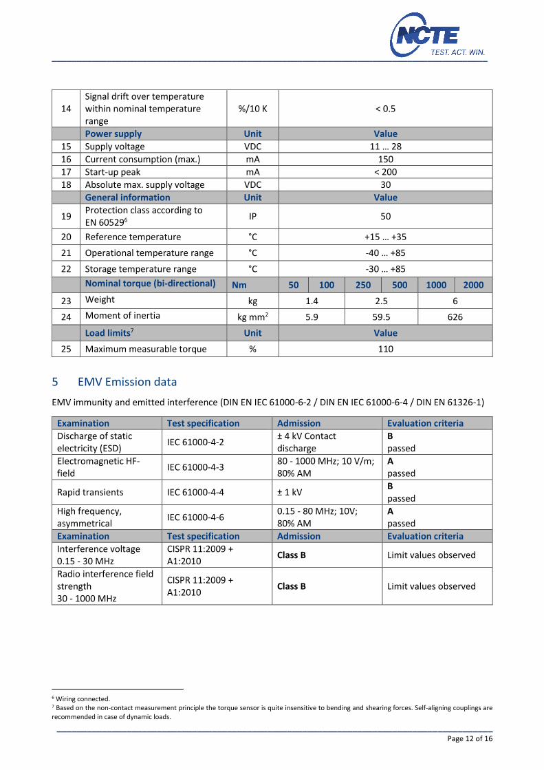
5 EMV Emission data
EMV immunity and emitted interference (DIN EN IEC 61000-6-2 / DIN EN IEC 61000-6-4 / DIN EN 61326-1)
Examination Test specification Admission Evaluation criteria
Discharge of static electricity (ESD)
IEC 61000-4-2 ± 4 kV Contact discharge
B passed
Electromagnetic HF-field
IEC 61000-4-3 80 - 1000 MHz; 10 V/m; 80% AM
A passed
Rapid transients IEC 61000-4-4 ± 1 kV B passed
High frequency, asymmetrical
IEC 61000-4-6 0.15 - 80 MHz; 10V; 80% AM
A passed
Examination Test specification Admission Evaluation criteria
Interference voltage 0.15 - 30 MHz
CISPR 11:2009 + A1:2010
Class B Limit values observed
Radio interference field strength 30 - 1000 MHz
CISPR 11:2009 + A1:2010
Class B Limit values observed
6 Wiring connected. 7 Based on the non-contact measurement principle the torque sensor is quite insensitive to bending and shearing forces. Self-aligning couplings are recommended in case of dynamic loads.
14 Signal drift over temperature within nominal temperature range
%/10 K < 0.5
Power supply Unit Value
15 Supply voltage VDC 11 … 28
16 Current consumption (max.) mA 150
17 Start-up peak mA < 200
18 Absolute max. supply voltage VDC 30
General information Unit Value
19 Protection class according to EN 605296
IP 50
20 Reference temperature °C +15 … +35
21 Operational temperature range °C -40 … +85
22 Storage temperature range °C -30 … +85
Nominal torque (bi-directional) Nm 50 100 250 500 1000 2000
23 Weight kg 1.4 2.5 6
24 Moment of inertia kg mm2 5.9 59.5 626
Load limits7 Unit Value
25 Maximum measurable torque % 110
_______________________________________________________________________________________
_______________________________________________________________________________________ Page 13 of 16
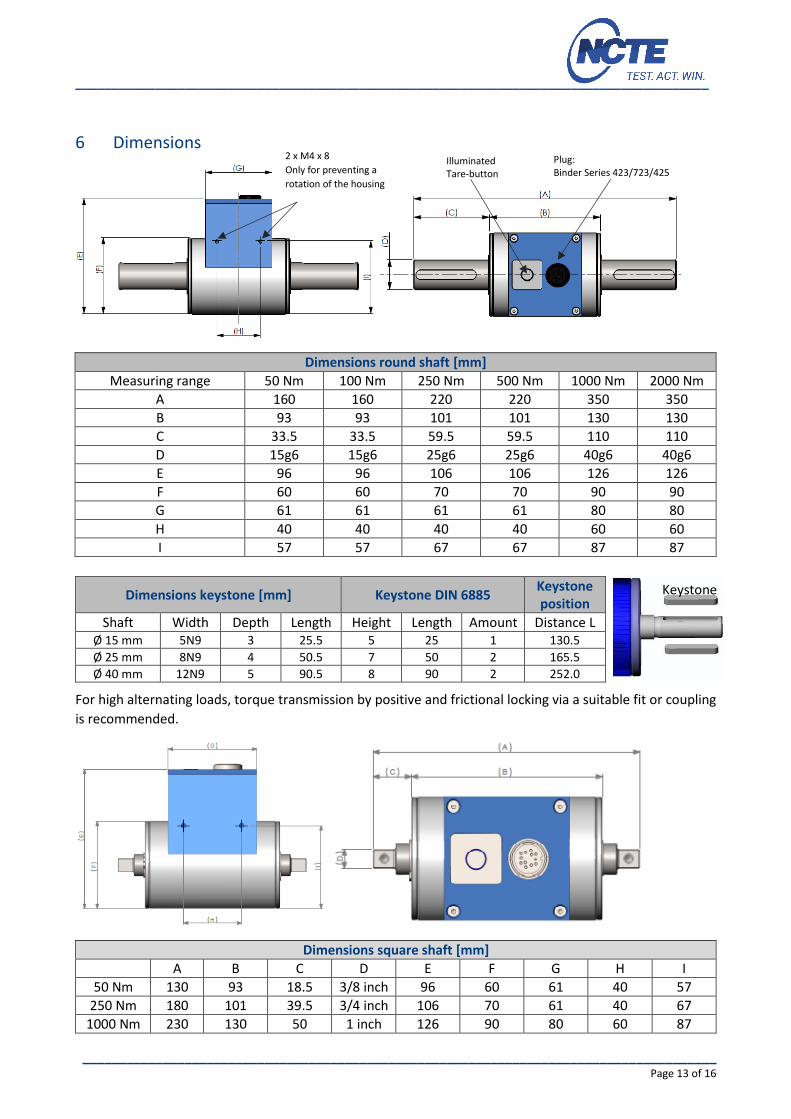
6 Dimensions
Dimensions round shaft [mm]
Measuring range 50 Nm 100 Nm 250 Nm 500 Nm 1000 Nm 2000 Nm
A 160 160 220 220 350 350
B 93 93 101 101 130 130
C 33.5 33.5 59.5 59.5 110 110
D 15g6 15g6 25g6 25g6 40g6 40g6
E 96 96 106 106 126 126
F 60 60 70 70 90 90
G 61 61 61 61 80 80
H 40 40 40 40 60 60
I 57 57 67 67 87 87
Dimensions keystone [mm] Keystone DIN 6885 Keystone position
Shaft Width Depth Length Height Length Amount Distance L
Ø 15 mm 5N9 3 25.5 5 25 1 130.5
Ø 25 mm 8N9 4 50.5 7 50 2 165.5
Ø 40 mm 12N9 5 90.5 8 90 2 252.0
For high alternating loads, torque transmission by positive and frictional locking via a suitable fit or coupling
is recommended.
Dimensions square shaft [mm]
A B C D E F G H I
50 Nm 130 93 18.5 3/8 inch 96 60 61 40 57
250 Nm 180 101 39.5 3/4 inch 106 70 61 40 67
1000 Nm 230 130 50 1 inch 126 90 80 60 87
Keystone
2 x M4 x 8
Only for preventing a
rotation of the housing
Illuminated Tare-button
Plug: Binder Series 423/723/425
_______________________________________________________________________________________
_______________________________________________________________________________________ Page 14 of 16
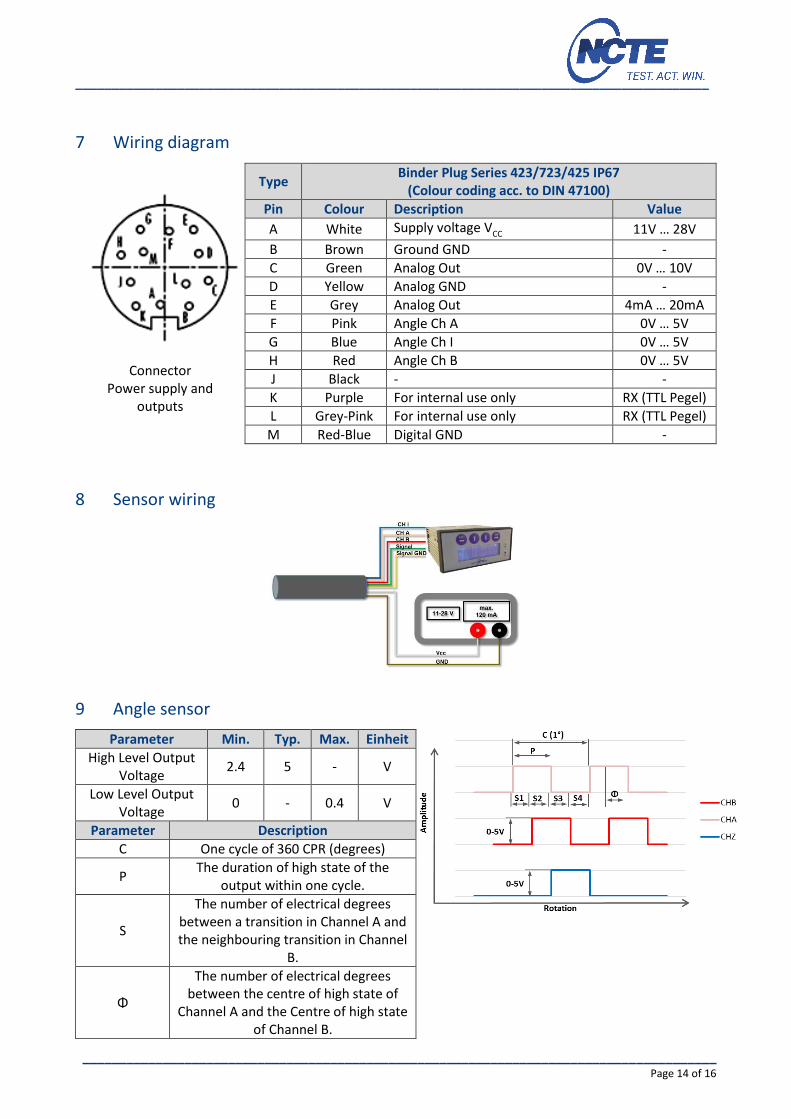
7 Wiring diagram
Connector
Power supply and outputs
Type Binder Plug Series 423/723/425 IP67
(Colour coding acc. to DIN 47100)
Pin Colour Description Value
A White Supply voltage VCC 11V … 28V
B Brown Ground GND -
C Green Analog Out 0V … 10V
D Yellow Analog GND -
E Grey Analog Out 4mA … 20mA
F Pink Angle Ch A 0V … 5V
G Blue Angle Ch I 0V … 5V
H Red Angle Ch B 0V … 5V
J Black - -
K Purple For internal use only RX (TTL Pegel)
L Grey-Pink For internal use only RX (TTL Pegel)
M Red-Blue Digital GND -
8 Sensor wiring
9 Angle sensor
Parameter Min. Typ. Max. Einheit
High Level Output Voltage
2.4 5 - V
Low Level Output Voltage
0 - 0.4 V
Parameter Description
C One cycle of 360 CPR (degrees)
P The duration of high state of the
output within one cycle.
S
The number of electrical degrees between a transition in Channel A and the neighbouring transition in Channel
B.
Φ
The number of electrical degrees between the centre of high state of
Channel A and the Centre of high state of Channel B.

_______________________________________________________________________________________
_______________________________________________________________________________________ Page 15 of 16
10 Order options
Series 3000 accuracy 0.2 %
Measuring range [Nm]
50 including 5m cable and calibration certificate
100 including 5m cable and calibration certificate
250 including 5m cable and calibration certificate
500 including 5m cable and calibration certificate
1000 including 5m cable and calibration certificate
2000 including 5m cable and calibration certificate
Angle sensor
0 Without angle sensor
1 Angle sensor 360 CPR
Analog output
A Voltage output 0-10V
S Current output 4-20mA
Shaft ends
0 Round shaft with keystone
1 Square shaft (available with 50/250/1000 Nm)
Protection class according to EN 60529
0 IP50
3000 100 1 A 0 0 Example Sensor configuration
We would be pleased to provide you with further information about serial products in a personal contact
under
Phone: +49 (0)89 66 56 19 30 or by e-mail: [email protected].
11 Accessories Readout unit
A Order number 400010-ATS001
(Art. No.: 400010005) Sensor input: Voltage output 0-5 V and 0-10 V 1 x angle encoder input, A/B USB interface, Software Windows included SD card slot to use for data logging
B Order number: 400010-ATS002 (Art. No.: 400010006)
Sensor input: current output 4-20 mA 1 x angle encoder input, A/B USB interface, Software for windows included SD card slot to use for data logging
Couplings
Coupling Type Used for D2 max.
KB4C/60-67-15-D2 3000/4000 – D 15 32
KB4C/150-78-15-D2 3000/4000 – D15 42
KB4C/300-94-25-D2 3000/4000 – D25 60
KB4C/500-100-25-D2 3000/4000 – D25 70
KB4/1400-168-40-D2 3000/4000 – D40 80
KB4C/300-94-19-D2 3000/4000 – D40 85
You can obtain further or additional accessories and special requests in a personal discussion with your
contact person for series products by calling +49 (0)89 66 56 19 30 or by e-mail: [email protected].

Your experts for magnetostrictive sensors