Embed Size (px)
Citation preview
1
INSTRUCTION MANUAL Micro-computer based Digital Indicating Controller ACS-13A
No.ACS12E2 2005.08
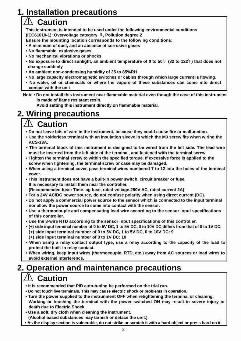
Preface Thank you for purchasing of our microcomputer based temperature indicating controller ACS-13A. This manual contains instructions for the mounting, functions, operations and notes when operating the ACS-13A. To prevent accidents arising from the misuse of this controller, please ensure the operator receives this manual. Characters used in this manual:
Number, / -1 0 1 2 3 4 5 6 7 8 9
Indication
Alphabet A B C D E F G H I J K L M
Indication
Alphabet N O P Q R S T U V W X Y Z
Indication
Notes • This instrument should be used in accordance with the specifications described in the manual.
If it is not used according to the specifications, it may malfunction or cause fire. • Be sure to follow the warnings, cautions and notices. If they are not observed, serious injury or malfunction may occur. • The contents of this instruction manual are subject to change without notice. • Care has been taken to assure that the contents of this instruction manual are correct, but if there are any doubts,
mistakes or questions, please inform our sales department. • This instrument is designed to be installed within a control panel. If it is not, measures must be taken to ensure that
the operator cannot touch power terminals or other high voltage sections. • Any unauthorized transfer or copying of this document, in part or in whole, is prohibited. • Shinko Technos CO., LTD. is not liable for any damages or secondary damages incurred as a result of using this product, including any indirect damages.
Safety precautions (Be sure to read these precautions before using our products.) The safety precautions are classified into categories: “Warning” and “Caution”. Depending on circumstances, procedures indicated by Caution may be linked to serious results, so be sure to follow the directions for usage.
Warning
Warning • To prevent an electric shock or fire, only Shinko or qualified service personnel may handle the inner assembly. • To prevent an electric shock, fire or damage to the instrument, parts replacement may only be undertaken
by Shinko or qualified service personnel.
Safety precautions • To ensure safe and correct use, thoroughly read and understand this manual before using this instrument. • This instrument is intended to be used for industrial machinery, machine tools and measuring equipment. Verify
correct usage after consulting the purpose of use with our agency or main office. (Never use this instrument for medical purposes with which human lives are involved.)
• External protection devices such as protection equipment against excessive temperature rise, etc. must be installed, as malfunction of this product could result in serious damage to the system or injury to personnel. Also proper periodic maintenance is required.
• This instrument must be used under the conditions and environment described in this manual. Shinko Technos Co., Ltd. does not accept liability for any injury, loss of life or damage occurring due to the instrument being used under conditions not otherwise stated in this manual.
Caution with respect to Export Trade Control Ordinance To avoid this instrument from being used as a component in, or as being utilized in the manufacture of weapons of mass destruction (i.e. military applications, military equipment, etc.), please investigate the end users and the final use of this instrument. In the case of resale, ensure that this instrument is not illegally exported.
Caution
Procedures which may lead to dangerous conditions and cause death or seriousinjury, if not carried out properly.
Procedures which may lead to dangerous conditions and cause superficial to medium injury or physical damage or may degrade or damage the product, if not carried outproperly.
2
1. Installation precautions Caution
This instrument is intended to be used under the following environmental conditions (IEC61010-1): Overvoltage category , Pollution degree 2 Ensure the mounting location corresponds to the following conditions: • A minimum of dust, and an absence of corrosive gases • No flammable, explosive gases • No mechanical vibrations or shocks • No exposure to direct sunlight, an ambient temperature of 0 to 50 (32 to 122 ) that does not change suddenly • An ambient non-condensing humidity of 35 to 85%RH • No large capacity electromagnetic switches or cables through which large current is flowing. • No water, oil or chemicals or where the vapors of these substances can come into direct
contact with the unit Note • Do not install this instrument near flammable material even though the case of this instrument
is made of flame resistant resin. Avoid setting this instrument directly on flammable material.
2. Wiring precautions Caution
• Do not leave bits of wire in the instrument, because they could cause fire or malfunction. • Use the solderless terminal with an insulation sleeve in which the M3 screw fits when wiring the
ACS-13A. • The terminal block of this instrument is designed to be wired from the left side. The lead wire
must be inserted from the left side of the terminal, and fastened with the terminal screw. • Tighten the terminal screw to within the specified torque. If excessive force is applied to the
screw when tightening, the terminal screw or case may be damaged. • When using a terminal cover, pass terminal wires numbered 7 to 12 into the holes of the terminal
cover. • This instrument does not have a built-in power switch, circuit breaker or fuse.
It is necessary to install them near the controller. (Recommended fuse: Time-lag fuse, rated voltage 250V AC, rated current 2A)
• For a 24V AC/DC power source, do not confuse polarity when using direct current (DC). • Do not apply a commercial power source to the sensor which is connected to the input terminal
nor allow the power source to come into contact with the sensor. • Use a thermocouple and compensating lead wire according to the sensor input specifications
of this controller. • Use the 3-wire RTD according to the sensor input specifications of this controller. • (+) side input terminal number of 0 to 5V DC, 1 to 5V DC, 0 to 10V DC differs from that of 0 to 1V DC.
(+) side input terminal number of 0 to 5V DC, 1 to 5V DC, 0 to 10V DC: 9 (+) side input terminal number of 0 to 1V DC: 10
• When using a relay contact output type, use a relay according to the capacity of the load toprotect the built-in relay contact.
• When wiring, keep input wires (thermocouple, RTD, etc.) away from AC sources or load wires toavoid external interference.
2. Operation and maintenance precautions
Caution • It is recommended that PID auto-tuning be performed on the trial run. • Do not touch live terminals. This may cause electric shock or problems in operation. • Turn the power supplied to the instrunment OFF when retightening the terminal or cleaning.
Working or touching the terminal with the power switched ON may result in severe injury ordeath due to Electric Shock.
• Use a soft, dry cloth when cleaning the instrument. (Alcohol based substances may tarnish or deface the unit.)
• As the display section is vulnerable, do not strike or scratch it with a hard object or press hard on it.
3
1. Model 1.1 Model
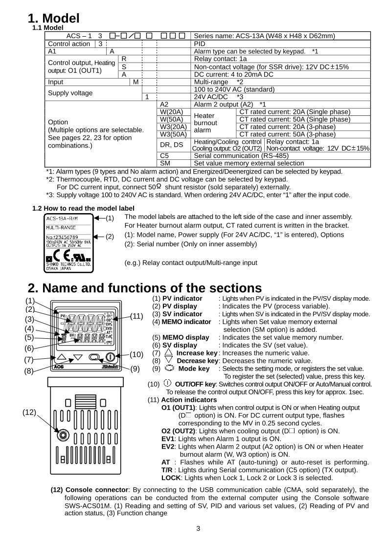
ACS – 1 3 , Series name: ACS-13A (W48 x H48 x D62mm) Control action 3 PID A1 A Alarm type can be selected by keypad. *1
R Relay contact: 1a S Non-contact voltage (for SSR drive): 12V DC 15% Control output, Heating
output: O1 (OUT1) A DC current: 4 to 20mA DC Input M Multi-range *2
100 to 240V AC (standard) Supply voltage 1 24V AC/DC *3 A2 Alarm 2 output (A2) *1 W(20A) CT rated current: 20A (Single phase) W(50A) CT rated current: 50A (Single phase) W3(20A) CT rated current: 20A (3-phase) W3(50A)
Heater burnout alarm CT rated current: 50A (3-phase)
DR, DS Heating/Cooling controlCooling output: O2 (OUT2)
Relay contact: 1a Non-contact voltage: 12V DC 15%
C5 Serial communication (RS-485)
Option (Multiple options are selectable. See pages 22, 23 for option combinations.)
SM Set value memory external selection *1: Alarm types (9 types and No alarm action) and Energized/Deenergized can be selected by keypad. *2: Thermocouple, RTD, DC current and DC voltage can be selected by keypad.
For DC current input, connect 50 shunt resistor (sold separately) externally. *3: Supply voltage 100 to 240V AC is standard. When ordering 24V AC/DC, enter “1” after the input code.
1.2 How to read the model label The model labels are attached to the left side of the case and inner assembly.
For Heater burnout alarm output, CT rated current is written in the bracket. (1): Model name, Power supply (For 24V AC/DC, “1” is entered), Options (2): Serial number (Only on inner assembly) (e.g.) Relay contact output/Multi-range input
2. Name and functions of the sections (1) PV indicator : Lights when PV is indicated in the PV/SV display mode. (2) PV display : Indicates the PV (process variable). (3) SV indicator : Lights when SV is indicated in the PV/SV display mode. (4) MEMO indicator : Lights when Set value memory external selection (SM option) is added.
(5) MEMO display : Indicates the set value memory number. (6) SV display : Indicates the SV (set value).
(7) Increase key : Increases the numeric value. (8) Decrease key : Decreases the numeric value. (9) Mode key : Selects the setting mode, or registers the set value. To register the set (selected) value, press this key. (10) OUT/OFF key: Switches control output ON/OFF or Auto/Manual control. To release the control output ON/OFF, press this key for approx. 1sec.
(11) Action indicators O1 (OUT1): Lights when control output is ON or when Heating output (D option) is ON. For DC current output type, flashes
corresponding to the MV in 0.25 second cycles. O2 (OUT2): Lights when cooling output (D option) is ON. EV1: Lights when Alarm 1 output is ON. EV2: Lights when Alarm 2 output (A2 option) is ON or when Heater burnout alarm (W, W3 option) is ON. AT : Flashes while AT (auto-tuning) or auto-reset is performing. T/R : Lights during Serial communication (C5 option) (TX output).
LOCK: Lights when Lock 1, Lock 2 or Lock 3 is selected.
(12) Console connector: By connecting to the USB communication cable (CMA, sold separately), the following operations can be conducted from the external computer using the Console software SWS-ACS01M. (1) Reading and setting of SV, PID and various set values, (2) Reading of PV and action status, (3) Function change
(1)
(2)
(1)
(3)(4)
(12)
(11)
(6) (7) (8)
(5)
(9)
(10)
(2)
4
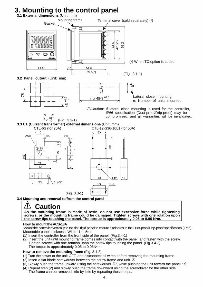
3. Mounting to the control panel 3.1 External dimensions (Unit: mm)
(Fig. 3.1-1)
3.2 Panel cutout (Unit: mm)
Lateral close mounting n: Number of units mounted
Caution: If lateral close mounting is used for the controller, IP66 specification (Dust-proof/Drip-proof) may be compromised, and all warranties will be invalidated. (Fig. 3.2-1)
3.3 CT (Current transformer) external dimensions (Unit: mm) CTL-6S (for 20A) CTL-12-S36-10L1 (for 50A)
3.4 Mounting and removal to/from the control panel
Caution As the mounting frame is made of resin, do not use excessive force while tightening screws, or the mounting frame could be damaged. Tighten screws with one rotation upon the screw tips touching the panel. The torque is approximately 0.05 to 0.06 N•m.
How to mount the ACS-13A Mount the controller vertically to the flat, rigid panel to ensure it adheres to the Dust-proof/Drip-proof specification (IP66). Mountable panel thickness: Within 1 to 5mm (1) Insert the controller from the front side of the panel. (Fig.3.4-1) (2) Insert the unit until mounting frame comes into contact with the panel, and fasten with the screw.
Tighten screws with one rotation upon the screw tips touching the panel. (Fig.3.4-2) The torque is approximately 0.05 to 0.06N•m.
How to remove the mounting frame (Fig. 3.4-3) (1) Turn the power to the unit OFF, and disconnect all wires before removing the mounting frame. (2) Insert a flat blade screwdriver between the screw frame and unit 1 . (3) Slowly push the frame upward using the screwdriver 2 , while pushing the unit toward the panel 3 . (4) Repeat step (2) and slowly push the frame downward using the screwdriver for the other side.
The frame can be removed little by little by repeating these steps.
75
45 +0.50
45+0
.5 0
45+0
.5 0
n x 48-3+0.50
Gasket Mounting frame Terminal cover (sold separately) (*)
(*) When TC option is added
(Fig. 3.3-1)
5
Terminal cover
(Fig.3.4-1)
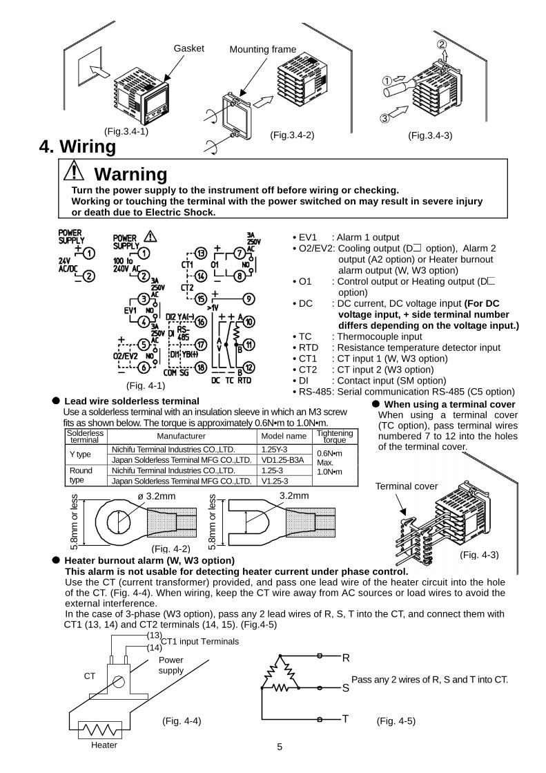
4. Wiring Warning
Turn the power supply to the instrument off before wiring or checking. Working or touching the terminal with the power switched on may result in severe injury or death due to Electric Shock.
• EV1 : Alarm 1 output • O2/EV2: Cooling output (D option), Alarm 2 output (A2 option) or Heater burnout alarm output (W, W3 option) • O1 : Control output or Heating output (D option) • DC : DC current, DC voltage input (For DC voltage input, + side terminal number
differs depending on the voltage input.) • TC : Thermocouple input • RTD : Resistance temperature detector input • CT1 : CT input 1 (W, W3 option) • CT2 : CT input 2 (W3 option) • DI : Contact input (SM option) • RS-485 : Serial communication RS-485 (C5 option)
Lead wire solderless terminal Use a solderless terminal with an insulation sleeve in which an M3 screw fits as shown below. The torque is approximately 0.6N•m to 1.0N•m. Solderless terminal Manufacturer Model name Tightening
torque Nichifu Terminal Industries CO.,LTD. 1.25Y-3 Y type Japan Solderless Terminal MFG CO.,LTD. VD1.25-B3A Nichifu Terminal Industries CO.,LTD. 1.25-3 Round
type Japan Solderless Terminal MFG CO.,LTD. V1.25-3
0.6N•m Max. 1.0N•m
Heater burnout alarm (W, W3 option)
This alarm is not usable for detecting heater current under phase control. Use the CT (current transformer) provided, and pass one lead wire of the heater circuit into the hole of the CT. (Fig. 4-4). When wiring, keep the CT wire away from AC sources or load wires to avoid the external interference. In the case of 3-phase (W3 option), pass any 2 lead wires of R, S, T into the CT, and connect them with CT1 (13, 14) and CT2 terminals (14, 15). (Fig.4-5)
Pass any 2 wires of R, S and T into CT.
When using a terminal coverWhen using a terminal cover(TC option), pass terminal wiresnumbered 7 to 12 into the holesof the terminal cover.
CT1 input Terminals
Powersupply
Heater
CT
(13)(14)
R
S
T(Fig. 4-4) (Fig. 4-5)
(Fig. 4-1)
(Fig.3.4-2) (Fig.3.4-3)
5.8m
m o
r les
s
(Fig. 4-2) 5.8m
m o
r les
s 3.2mmø 3.2mm
Gasket Mounting frame
(Fig. 4-3)
6
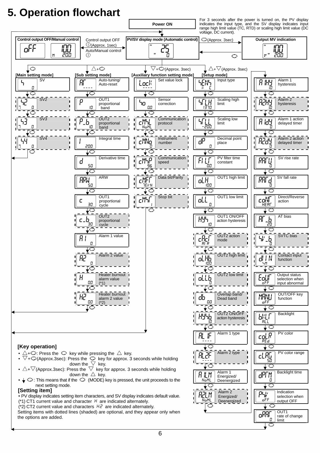
5. Operation flowchart
Control output OFF/Manual control Control output OFF (Approx. 1sec)
Auto/Manual control
PV/SV display mode (Automatic control)
(Approx. 3sec)
Output MV indication
+ + (Approx. 3sec) + (Approx. 3sec)
[Main setting mode] [Sub setting mode] [Auxiliary function setting mode] [Setup mode] SV Auto-tuning/
Auto-reset Set value lock
Input type
Alarm 1
hysteresis
SV2
OUT1 proportional
band
Sensor correction
Scaling high limit
Alarm 2 hysteresis
SV3
OUT2 proportional
band
Communication protocol
Scaling low limit
Alarm 1 action delayed timer
SV4
Integral time
Instrument number
Decimal point place
Alarm 2 action delayed timer
Derivative time
Communication speed
PV filter time constant
SV rise rate
ARW Data bit/Parity
OUT1 high limit
SV fall rate
OUT1 proportional cycle
Stop bit
OUT1 low limit
Direct/Reverse action
OUT2
proportional cycle
OUT1 ON/OFF action hysteresis
AT bias
Alarm 1 value OUT2 action
mode SVTC bias
Alarm 2 value OUT2 high limit
Contact input
function
Heater burnout
alarm value (*1)
OUT2 low limit
Output status selection when input abnormal
Heater burnout
alarm 2 value (*2)
Overlap band/ Dead band
OUT/OFF key function
OUT2 ON/OFF
action hysteresis
Backlight
Alarm 1 type
PV color
[Key operation] Alarm 2 type
PV color range
Alarm 1
Energized/ Deenergized
Backlight time
Alarm 2
Energized/ Deenergized
Indication selection when output OFF
• + : Press the key while pressing the key. • + (Approx.3sec): Press the key for approx. 3 seconds while holding down the key. • + (Approx.3sec): Press the key for approx. 3 seconds while holding down the key. • : This means that if the (MODE) key is pressed, the unit proceeds to the
next setting mode. [Setting item] • PV display indicates setting item characters, and SV display indicates default value. (*1) CT1 current value and character are indicated alternately. (*2) CT2 current value and characters are indicated alternately. Setting items with dotted lines (shaded) are optional, and they appear only when the options are added.
OUT1 rate of change limit
Power ON For 3 seconds after the power is turned on, the PV displayindicates the input type, and the SV display indicates inputrange high limit value (TC, RTD) or scaling high limit value (DCvoltage, DC current).
7
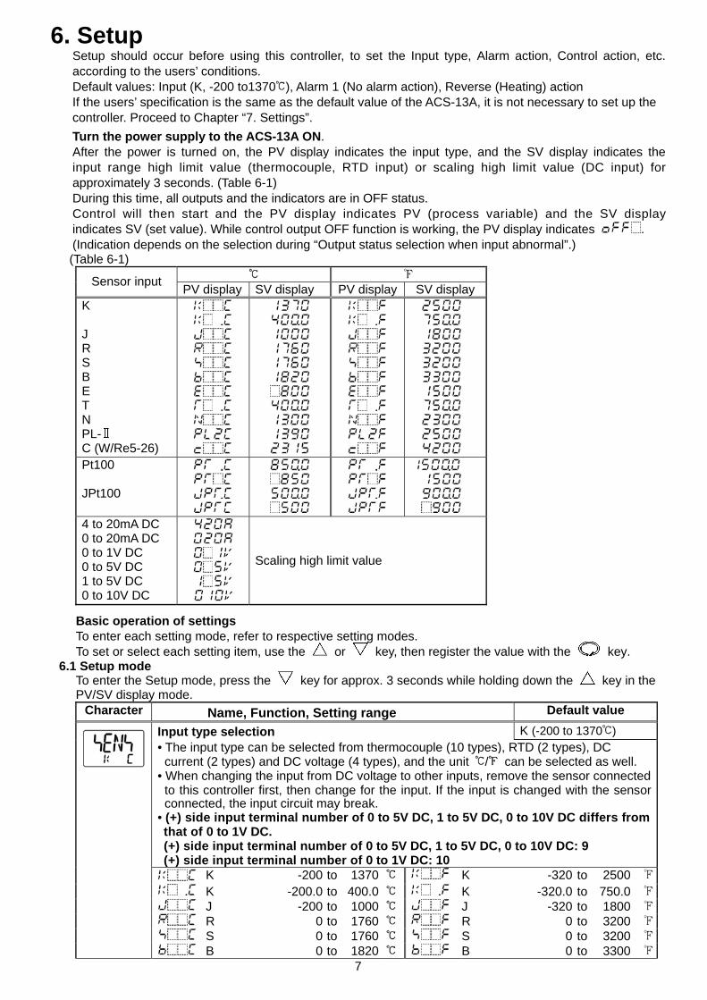
6. Setup Setup should occur before using this controller, to set the Input type, Alarm action, Control action, etc. according to the users’ conditions. Default values: Input (K, -200 to1370 ), Alarm 1 (No alarm action), Reverse (Heating) action If the users’ specification is the same as the default value of the ACS-13A, it is not necessary to set up the controller. Proceed to Chapter “7. Settings”. Turn the power supply to the ACS-13A ON. After the power is turned on, the PV display indicates the input type, and the SV display indicates the input range high limit value (thermocouple, RTD input) or scaling high limit value (DC input) for approximately 3 seconds. (Table 6-1) During this time, all outputs and the indicators are in OFF status. Control will then start and the PV display indicates PV (process variable) and the SV display indicates SV (set value). While control output OFF function is working, the PV display indicates . (Indication depends on the selection during “Output status selection when input abnormal”.)
(Table 6-1) Sensor input PV display SV display PV display SV display
K J R S B E T N PL- C (W/Re5-26)
Pt100 JPt100
4 to 20mA DC 0 to 20mA DC 0 to 1V DC 0 to 5V DC 1 to 5V DC 0 to 10V DC
Scaling high limit value
Basic operation of settings To enter each setting mode, refer to respective setting modes. To set or select each setting item, use the or key, then register the value with the key.
6.1 Setup mode To enter the Setup mode, press the key for approx. 3 seconds while holding down the key in the PV/SV display mode.
Character Name, Function, Setting range Default value Input type selection K (-200 to 1370 ) • The input type can be selected from thermocouple (10 types), RTD (2 types), DC
current (2 types) and DC voltage (4 types), and the unit / can be selected as well. • When changing the input from DC voltage to other inputs, remove the sensor connected
to this controller first, then change for the input. If the input is changed with the sensorconnected, the input circuit may break.
• (+) side input terminal number of 0 to 5V DC, 1 to 5V DC, 0 to 10V DC differs fromthat of 0 to 1V DC. (+) side input terminal number of 0 to 5V DC, 1 to 5V DC, 0 to 10V DC: 9 (+) side input terminal number of 0 to 1V DC: 10
K -200 to 1370 K -320 to 2500 K -200.0 to 400.0 K -320.0 to 750.0 J -200 to 1000 J -320 to 1800 R 0 to 1760 R 0 to 3200 S 0 to 1760 S 0 to 3200
B 0 to 1820 B 0 to 3300
8
SV setting
OUT2 proportional band
Air cooling
Oil coolingWater cooling
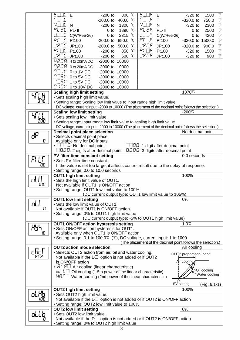
E -200 to 800 E -320 to 1500 T -200.0 to 400.0 T -320.0 to 750.0 N -200 to 1300 N -320 to 2300 PL- 0 to 1390 PL- 0 to 2500 C(W/Re5-26) 0 to 2315 C(W/Re5-26) 0 to 4200 Pt100 -200.0 to 850.0 Pt100 -320.0 to 1500.0 JPt100 -200.0 to 500.0 JPt100 -320.0 to 900.0 Pt100 -200 to 850 Pt100 -320 to 1500 JPt100 -200 to 500 JPt100 -320 to 900 4 to 20mA DC -2000 to 10000 0 to 20mA DC -2000 to 10000 0 to 1V DC -2000 to 10000 0 to 5V DC -2000 to 10000 1 to 5V DC -2000 to 10000
0 to 10V DC -2000 to 10000 Scaling high limit setting 1370 • Sets scaling high limit value. • Setting range: Scaling low limit value to input range high limit value
DC voltage, current input: -2000 to 10000 (The placement of the decimal point follows the selection.) Scaling low limit setting -200 • Sets scaling low limit value. • Setting range: Input range low limit value to scaling high limit value
DC voltage, current input: -2000 to 10000 (The placement of the decimal point follows the selection.) Decimal point place selection No decimal point • Selects decimal point place. Available only for DC inputs • : No decimal point : 1 digit after decimal point
: 2 digits after decimal point : 3 digits after decimal point PV filter time constant setting 0.0 seconds • Sets PV filter time constant.
If the value is set too large, it affects control result due to the delay of response. • Setting range: 0.0 to 10.0 seconds OUT1 high limit setting 100% • Sets the high limit value of OUT1.
Not available if OUT1 is ON/OFF action • Setting range: OUT1 low limit value to 100%
(DC current output type: OUT1 low limit value to 105%) OUT1 low limit setting 0% • Sets the low limit value of OUT1. Not available if OUT1 is ON/OFF action. • Setting range: 0% to OUT1 high limit value
(DC current output type: -5% to OUT1 high limit value) OUT1 ON/OFF action hysteresis setting 1.0 • Sets ON/OFF action hysteresis for OUT1. Available only when OUT1 is ON/OFF action • Setting range: 0.1 to 100.0 ( ), DC voltage, current input: 1 to 1000 (The placement of the decimal point follows the selection.)
OUT2 action mode selection Air cooling • Selects OUT2 action from air, oil and water cooling. Not available if the D option is not added or if OUT2
is ON/OFF action • Air cooling (linear characteristic)
Oil cooling (1.5th power of the linear characteristic) Water cooling (2nd power of the linear characteristic)
(Fig. 6.1-1)OUT2 high limit setting 100% • Sets OUT2 high limit value. Not available if the D option is not added or if OUT2 is ON/OFF action • Setting range: OUT2 low limit value to 100% OUT2 low limit setting 0% • Sets OUT2 low limit value. Not available if the D option is not added or if OUT2 is ON/OFF action • Setting range: 0% to OUT2 high limit value
9
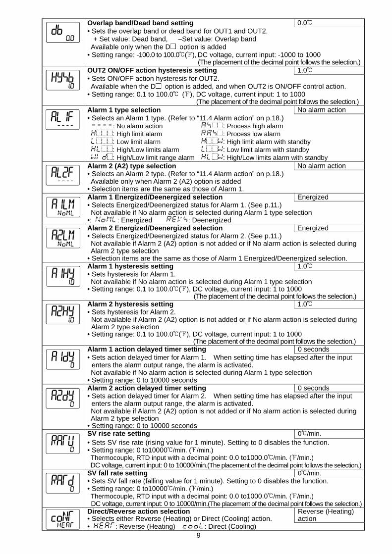
Overlap band/Dead band setting 0.0 • Sets the overlap band or dead band for OUT1 and OUT2.
+ Set value: Dead band, –Set value: Overlap band Available only when the D option is added • Setting range: -100.0 to 100.0 ( ), DC voltage, current input: -1000 to 1000
(The placement of the decimal point follows the selection.) OUT2 ON/OFF action hysteresis setting 1.0 • Sets ON/OFF action hysteresis for OUT2. Available when the D option is added, and when OUT2 is ON/OFF control action. • Setting range: 0.1 to 100.0 ( ), DC voltage, current input: 1 to 1000 (The placement of the decimal point follows the selection.) Alarm 1 type selection No alarm action • Selects an Alarm 1 type. (Refer to “11.4 Alarm action” on p.18.) : No alarm action : Process high alarm : High limit alarm : Process low alarm : Low limit alarm : High limit alarm with standby : High/Low limits alarm : Low limit alarm with standby : High/Low limit range alarm : High/Low limits alarm with standby Alarm 2 (A2) type selection No alarm action • Selects an Alarm 2 type. (Refer to “11.4 Alarm action” on p.18.) Available only when Alarm 2 (A2) option is added • Selection items are the same as those of Alarm 1. Alarm 1 Energized/Deenergized selection Energized • Selects Energized/Deenergized status for Alarm 1. (See p.11.) Not available if No alarm action is selected during Alarm 1 type selection •: : Energized : Deenergized Alarm 2 Energized/Deenergized selection Energized • Selects Energized/Deenergized status for Alarm 2. (See p.11.) Not available if Alarm 2 (A2) option is not added or if No alarm action is selected during Alarm 2 type selection • Selection items are the same as those of Alarm 1 Energized/Deenergized selection. Alarm 1 hysteresis setting 1.0 • Sets hysteresis for Alarm 1. Not available if No alarm action is selected during Alarm 1 type selection • Setting range: 0.1 to 100.0 ( ), DC voltage, current input: 1 to 1000 (The placement of the decimal point follows the selection.) Alarm 2 hysteresis setting 1.0 • Sets hysteresis for Alarm 2.
Not available if Alarm 2 (A2) option is not added or if No alarm action is selected during Alarm 2 type selection
• Setting range: 0.1 to 100.0 ( ), DC voltage, current input: 1 to 1000 (The placement of the decimal point follows the selection.) Alarm 1 action delayed timer setting 0 seconds • Sets action delayed timer for Alarm 1. When setting time has elapsed after the input
enters the alarm output range, the alarm is activated. Not available if No alarm action is selected during Alarm 1 type selection • Setting range: 0 to 10000 seconds Alarm 2 action delayed timer setting 0 seconds • Sets action delayed timer for Alarm 2. When setting time has elapsed after the input
enters the alarm output range, the alarm is activated. Not available if Alarm 2 (A2) option is not added or if No alarm action is selected during Alarm 2 type selection • Setting range: 0 to 10000 seconds SV rise rate setting 0 /min. • Sets SV rise rate (rising value for 1 minute). Setting to 0 disables the function. • Setting range: 0 to10000 /min. ( /min.) Thermocouple, RTD input with a decimal point: 0.0 to1000.0 /min. ( /min.) DC voltage, current input: 0 to 10000/min.(The placement of the decimal point follows the selection.)
SV fall rate setting 0 /min. • Sets SV fall rate (falling value for 1 minute). Setting to 0 disables the function. • Setting range: 0 to10000 /min. ( /min.) Thermocouple, RTD input with a decimal point: 0.0 to1000.0 /min. ( /min.) DC voltage, current input: 0 to 10000/min.(The placement of the decimal point follows the selection.)
Direct/Reverse action selection • Selects either Reverse (Heating) or Direct (Cooling) action.
Reverse (Heating) action
• : Reverse (Heating) : Direct (Cooling)
10
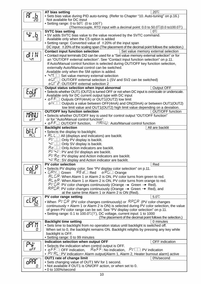
AT bias setting 20 • Sets bias value during PID auto-tuning. (Refer to Chapter “10. Auto-tuning” on p.16.) Not available for DC input • Setting range: 0 to 50 (0 to 100 )
(Thermocouple, RTD input with a decimal point: 0.0 to 50.0 (0.0 to100.0 ) SVTC bias setting 0 • SV adds SVTC bias value to the value received by the SVTC command.
Available only when the C5 option is added • Setting range: Converted value of 20% of the input span DC input: 20% of the scaling span (The placement of the decimal point follows the selection.) Contact input function selection Set value memory external selection • Contact input terminals DI2 can be used for a “Set value memory external selection” or for
an “OUT/OFF external selection”. See “Contact input function selection” on p.11. If Auto/Manual control function is selected during OUT/OFF key function selection, externally Auto/Manual control can be switched.
Available only when the SM option is added. • : Set value memory external selection
: OUT/OFF external selection 1 (SV and SV2 can be switched) : OUT/OFF external selection 2
Output status selection when input abnormal Output OFF • Selects whether OUT1 (OUT2) is turned OFF or not when DC input is overscale or underscale. Available only for DC current output type with DC input • : Outputs OFF(4mA) or OUT1(OUT2) low limit
: Outputs a value between OFF(4mA) and ON(20mA) or between OUT1(OUT2) low limit value and OUT1(OUT2) high limit value depending on a deviation.
OUT/OFF key function selection OUT/OFF function • Selects whether OUT/OFF key is used for control output “OUT/OFF function” or for “Auto/Manual control function”. • : OUT/OFF function, : Auto/Manual control function Backlight selection All are backlit • Selects the display to backlight. • : All (displays and indicators) are backlit.
: Only PV display is backlit. : Only SV display is backlit. : Only Action indicators are backlit. : PV and SV displays are backlit. : PV display and Action indicators are backlit. : SV display and Action indicator are backlit.
PV color selection Red • Selects PV display color. See “PV display color selection” on p.11. • : Green : Red : Orange
: When Alarm 1 or Alarm 2 is ON, PV color turns from green to red. : When Alarm 1 or Alarm 2 is ON, PV color turns from orange to red. : PV color changes continuously (Orange Green Red). : PV color changes continuously (Orange Green Red), and
at the same time Alarm 1 or Alarm 2 is ON (Red). PV color range setting 5.0
• When (PV color changes continuously) or (PV color changes continuously + Alarm 1 or Alarm 2 is ON) is selected during PV color selection, the valueof green PV color range can be set. See “PV display color selection” on p.11.
• Setting range: 0.1 to 100.0 ( ), DC voltage, current input: 1 to 1000 (The placement of the decimal point follows the selection.) Backlight time setting 0 minutes • Sets time to backlight from no operation status until backlight is switched off. When set to 0, the backlight remains ON. Backlight relights by pressing any key while backlight is OFF.
• Setting range: 0 to 99 minutes Indication selection when output OFF OFF indication • Selects the indication when control output is OFF. • : OFF indication, : No indication, : PV indication • : PV indication+ Alarm output(Alarm 1, Alarm 2, Heater burnout alarm) active OUT1 rate of change limit 0%/second • Sets changing value of OUT1 MV for 1 second. • Not available if OUT1 is ON/OFF action, or when set to 0. • 0 to 100%/second
11
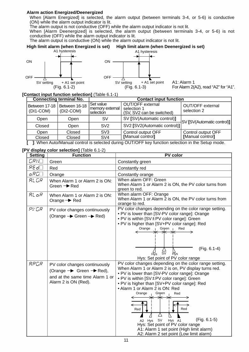
Alarm action Energized/Deenergized When [Alarm Energized] is selected, the alarm output (between terminals 3-4, or 5-6) is conductive (ON) while the alarm output indicator is lit. The alarm output is not conductive (OFF) while the alarm output indicator is not lit. When [Alarm Deenergized] is selected, the alarm output (between terminals 3-4, or 5-6) is not conductive (OFF) while the alarm output indicator is lit. The alarm output is conductive (ON) while the alarm output indicator is not lit.
High limit alarm (when Energized is set) High limit alarm (when Deenergized is set) A1: Alarm 1 (Fig. 6.1-2) (Fig. 6.1-3) For Alarm 2(A2), read “A2” for “A1”.
[Contact input function selection] (Table 6.1-1) Connecting terminal No. Contact input function
Between 17-18 (DI1-COM)
Between 16-18 (DI2-COM)
Set value memory externalselection
OUT/OFF external selection 1 (SV, SV2 can be switched)
OUT/OFF external selection 2
Open Open SV SV [SV(Automatic control)] Closed Open SV2 SV2 [SV2(Automatic control)]
SV [SV(Automatic control)]
Open Closed SV3 Closed Closed SV4
Control output OFF [Manual control]
Control output OFF [Manual control]
[ ]: When Auto/Manual control is selected during OUT/OFF key function selection in the Setup mode. [PV display color selection] (Table 6.1-2)
Setting Function PV color Green Constantly green Red Constantly red Orange Constantly orange
When Alarm 1 or Alarm 2 is ON: Green Red
When alarm OFF: Green When Alarm 1 or Alarm 2 is ON, the PV color turns from green to red.
When Alarm 1 or Alarm 2 is ON: Orange Red
When alarm OFF: Orange When Alarm 1 or Alarm 2 is ON, the PV color turns from orange to red.
PV color changes continuously (Orange Green Red)
PV color changes depending on the color range setting. • PV is lower than [SV-PV color range]: Orange • PV is within [SV PV color range]: Green • PV is higher than [SV+PV color range]: Red (Fig. 6.1-4) Hys: Set point of PV color range
PV color changes continuously (Orange Green Red), and at the same time Alarm 1 or Alarm 2 is ON (Red).
PV color changes depending on the color range setting. When Alarm 1 or Alarm 2 is on, PV display turns red. • PV is lower than [SV-PV color range]: Orange • PV is within [SV PV color range]: Green • PV is higher than [SV+PV color range]: Red • Alarm 1 or Alarm 2 is ON: Red (Fig. 6.1-5) Hys: Set point of PV color range A1: Alarm 1 set point (High limit alarm) A2: Alarm 2 set point (Low limit alarm)
OFF
ON
A1 hysteresis
SV setting + A1 set pointOFF
ON
SV setting + A1 set point
A1 hysteresis
Hys HysSV
Orange Green Red
Hys HysSV A1A2
Orange Green Red
RedRed
12
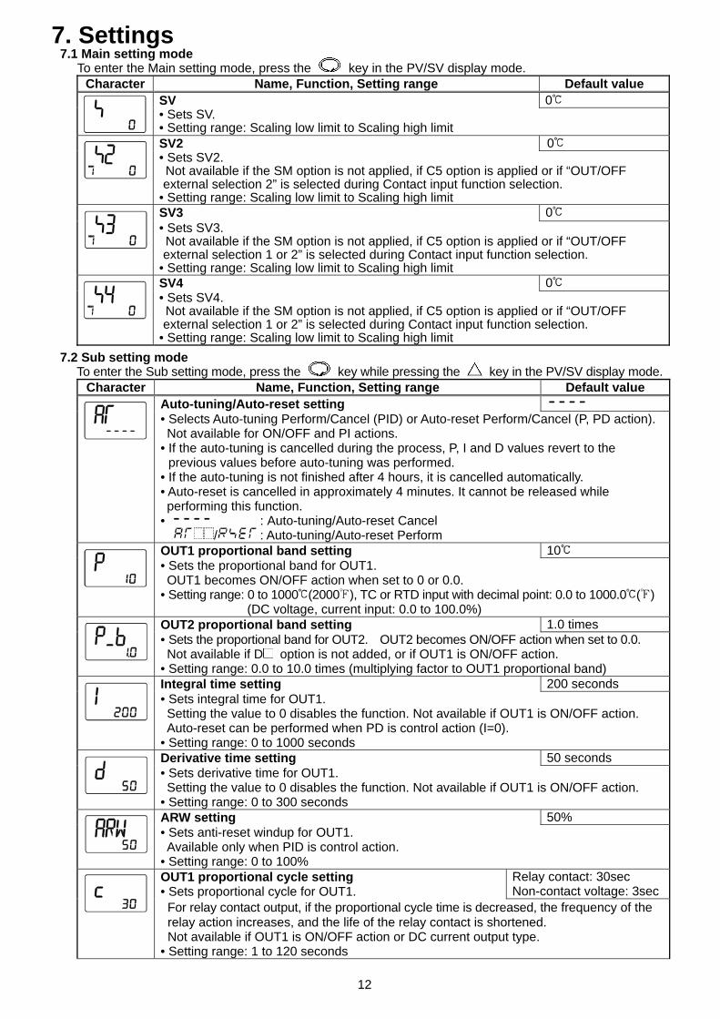
7. Settings 7.1 Main setting mode
To enter the Main setting mode, press the key in the PV/SV display mode. Character Name, Function, Setting range Default value
SV 0 • Sets SV. • Setting range: Scaling low limit to Scaling high limit SV2 0 • Sets SV2. Not available if the SM option is not applied, if C5 option is applied or if “OUT/OFF external selection 2” is selected during Contact input function selection.
• Setting range: Scaling low limit to Scaling high limit SV3 0 • Sets SV3. Not available if the SM option is not applied, if C5 option is applied or if “OUT/OFF external selection 1 or 2” is selected during Contact input function selection.
• Setting range: Scaling low limit to Scaling high limit SV4 0 • Sets SV4. Not available if the SM option is not applied, if C5 option is applied or if “OUT/OFF external selection 1 or 2” is selected during Contact input function selection.
• Setting range: Scaling low limit to Scaling high limit 7.2 Sub setting mode
To enter the Sub setting mode, press the key while pressing the key in the PV/SV display mode. Character Name, Function, Setting range Default value
Auto-tuning/Auto-reset setting
• Selects Auto-tuning Perform/Cancel (PID) or Auto-reset Perform/Cancel (P, PD action). Not available for ON/OFF and PI actions. • If the auto-tuning is cancelled during the process, P, I and D values revert to the
previous values before auto-tuning was performed. • If the auto-tuning is not finished after 4 hours, it is cancelled automatically. • Auto-reset is cancelled in approximately 4 minutes. It cannot be released while performing this function. • : Auto-tuning/Auto-reset Cancel / : Auto-tuning/Auto-reset Perform OUT1 proportional band setting 10 • Sets the proportional band for OUT1. OUT1 becomes ON/OFF action when set to 0 or 0.0. • Setting range: 0 to 1000 (2000 ), TC or RTD input with decimal point: 0.0 to 1000.0 ( )
(DC voltage, current input: 0.0 to 100.0%) OUT2 proportional band setting 1.0 times • Sets the proportional band for OUT2. OUT2 becomes ON/OFF action when set to 0.0. Not available if D option is not added, or if OUT1 is ON/OFF action. • Setting range: 0.0 to 10.0 times (multiplying factor to OUT1 proportional band) Integral time setting 200 seconds • Sets integral time for OUT1. Setting the value to 0 disables the function. Not available if OUT1 is ON/OFF action. Auto-reset can be performed when PD is control action (I=0). • Setting range: 0 to 1000 seconds Derivative time setting 50 seconds • Sets derivative time for OUT1. Setting the value to 0 disables the function. Not available if OUT1 is ON/OFF action. • Setting range: 0 to 300 seconds ARW setting 50% • Sets anti-reset windup for OUT1. Available only when PID is control action. • Setting range: 0 to 100% OUT1 proportional cycle setting • Sets proportional cycle for OUT1.
Relay contact: 30sec Non-contact voltage: 3sec
For relay contact output, if the proportional cycle time is decreased, the frequency of the relay action increases, and the life of the relay contact is shortened. Not available if OUT1 is ON/OFF action or DC current output type.
• Setting range: 1 to 120 seconds
13
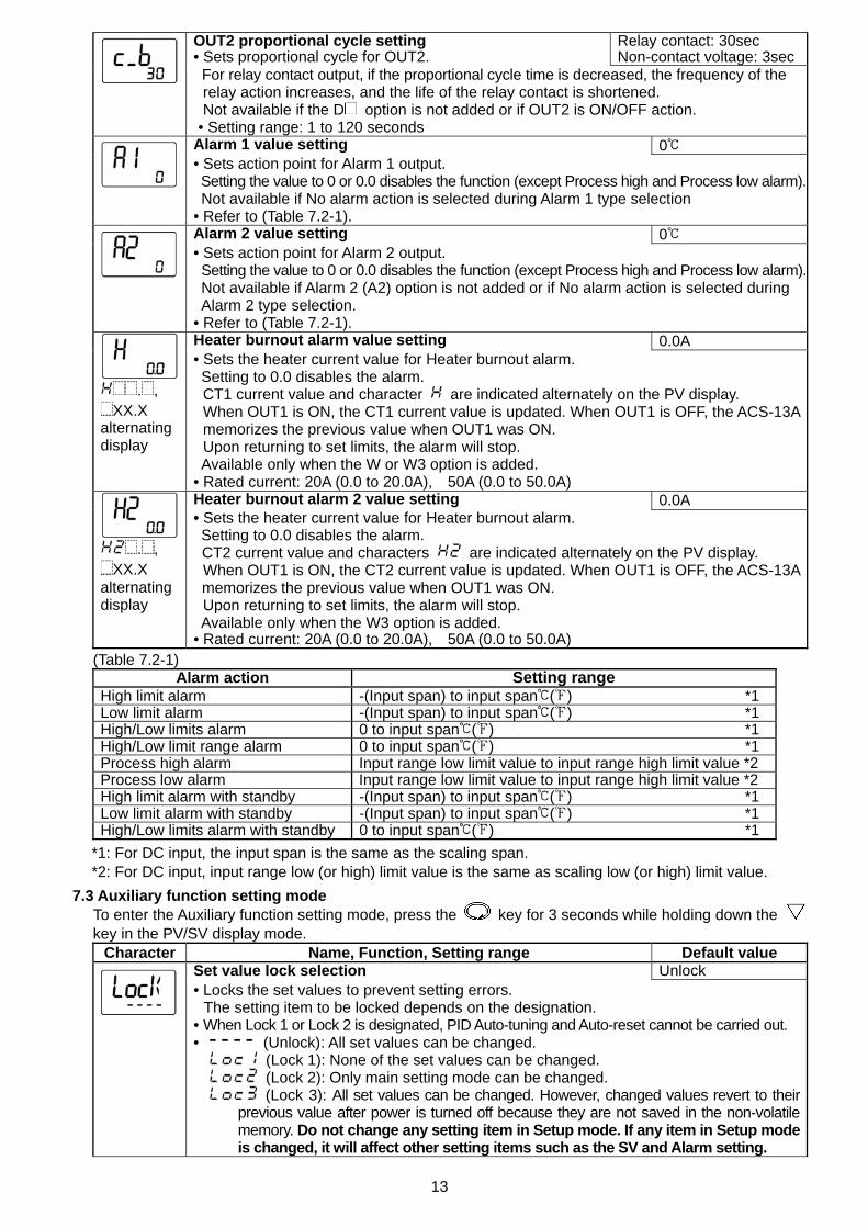
OUT2 proportional cycle setting • Sets proportional cycle for OUT2.
Relay contact: 30sec Non-contact voltage: 3sec
For relay contact output, if the proportional cycle time is decreased, the frequency of the relay action increases, and the life of the relay contact is shortened. Not available if the D option is not added or if OUT2 is ON/OFF action.
• Setting range: 1 to 120 seconds Alarm 1 value setting 0 • Sets action point for Alarm 1 output. Setting the value to 0 or 0.0 disables the function (except Process high and Process low alarm).
Not available if No alarm action is selected during Alarm 1 type selection • Refer to (Table 7.2-1). Alarm 2 value setting 0 • Sets action point for Alarm 2 output. Setting the value to 0 or 0.0 disables the function (except Process high and Process low alarm).
Not available if Alarm 2 (A2) option is not added or if No alarm action is selected during Alarm 2 type selection. • Refer to (Table 7.2-1). Heater burnout alarm value setting 0.0A
. ,
XX.X alternating display
• Sets the heater current value for Heater burnout alarm. Setting to 0.0 disables the alarm.
CT1 current value and character are indicated alternately on the PV display. When OUT1 is ON, the CT1 current value is updated. When OUT1 is OFF, the ACS-13Amemorizes the previous value when OUT1 was ON. Upon returning to set limits, the alarm will stop.
Available only when the W or W3 option is added. • Rated current: 20A (0.0 to 20.0A), 50A (0.0 to 50.0A) Heater burnout alarm 2 value setting 0.0A
. ,
XX.X alternating display
• Sets the heater current value for Heater burnout alarm. Setting to 0.0 disables the alarm. CT2 current value and characters are indicated alternately on the PV display. When OUT1 is ON, the CT2 current value is updated. When OUT1 is OFF, the ACS-13Amemorizes the previous value when OUT1 was ON. Upon returning to set limits, the alarm will stop. Available only when the W3 option is added.
• Rated current: 20A (0.0 to 20.0A), 50A (0.0 to 50.0A) (Table 7.2-1)
Alarm action Setting range High limit alarm -(Input span) to input span ( ) *1 Low limit alarm -(Input span) to input span ( ) *1 High/Low limits alarm 0 to input span ( ) *1 High/Low limit range alarm 0 to input span ( ) *1 Process high alarm Input range low limit value to input range high limit value *2 Process low alarm Input range low limit value to input range high limit value *2 High limit alarm with standby -(Input span) to input span ( ) *1 Low limit alarm with standby -(Input span) to input span ( ) *1 High/Low limits alarm with standby 0 to input span ( ) *1
*1: For DC input, the input span is the same as the scaling span. *2: For DC input, input range low (or high) limit value is the same as scaling low (or high) limit value.
7.3 Auxiliary function setting mode To enter the Auxiliary function setting mode, press the key for 3 seconds while holding down the key in the PV/SV display mode.
Character Name, Function, Setting range Default value Set value lock selection Unlock • Locks the set values to prevent setting errors.
The setting item to be locked depends on the designation. • When Lock 1 or Lock 2 is designated, PID Auto-tuning and Auto-reset cannot be carried out. • (Unlock) : All set values can be changed. (Lock 1): None of the set values can be changed. (Lock 2): Only main setting mode can be changed. (Lock 3): All set values can be changed. However, changed values revert to their
previous value after power is turned off because they are not saved in the non-volatilememory. Do not change any setting item in Setup mode. If any item in Setup modeis changed, it will affect other setting items such as the SV and Alarm setting.
14
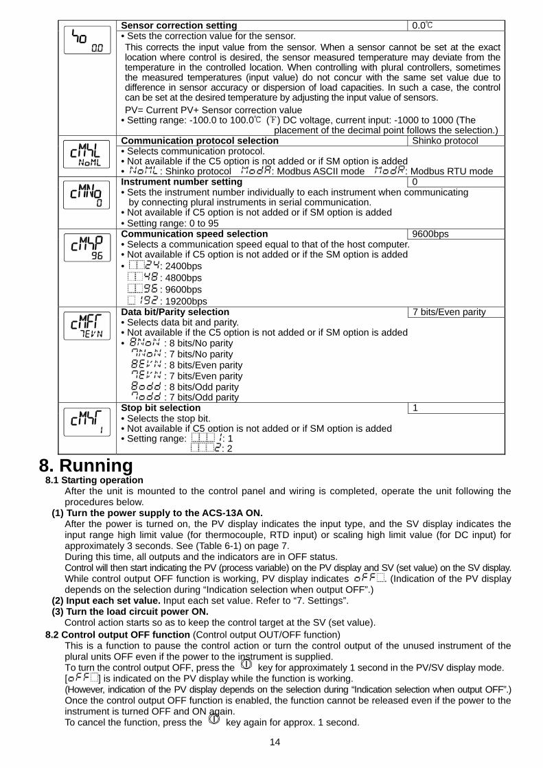
Sensor correction setting 0.0 • Sets the correction value for the sensor. This corrects the input value from the sensor. When a sensor cannot be set at the exact location where control is desired, the sensor measured temperature may deviate from the temperature in the controlled location. When controlling with plural controllers, sometimes the measured temperatures (input value) do not concur with the same set value due to difference in sensor accuracy or dispersion of load capacities. In such a case, the control can be set at the desired temperature by adjusting the input value of sensors. PV= Current PV+ Sensor correction value
• Setting range: -100.0 to 100.0 ( ) DC voltage, current input: -1000 to 1000 (The placement of the decimal point follows the selection.) Communication protocol selection Shinko protocol • Selects communication protocol. • Not available if the C5 option is not added or if SM option is added • : Shinko protocol : Modbus ASCII mode : Modbus RTU mode Instrument number setting 0 • Sets the instrument number individually to each instrument when communicating
by connecting plural instruments in serial communication. • Not available if C5 option is not added or if SM option is added • Setting range: 0 to 95 Communication speed selection 9600bps • Selects a communication speed equal to that of the host computer. • Not available if C5 option is not added or if the SM option is added • : 2400bps
: 4800bps : 9600bps : 19200bps
Data bit/Parity selection 7 bits/Even parity • Selects data bit and parity. • Not available if the C5 option is not added or if SM option is added • : 8 bits/No parity : 7 bits/No parity
: 8 bits/Even parity : 7 bits/Even parity : 8 bits/Odd parity : 7 bits/Odd parity
Stop bit selection 1 • Selects the stop bit. • Not available if C5 option is not added or if SM option is added • Setting range: : 1
: 2
8. Running 8.1 Starting operation
After the unit is mounted to the control panel and wiring is completed, operate the unit following the procedures below.
(1) Turn the power supply to the ACS-13A ON. After the power is turned on, the PV display indicates the input type, and the SV display indicates the input range high limit value (for thermocouple, RTD input) or scaling high limit value (for DC input) for approximately 3 seconds. See (Table 6-1) on page 7. During this time, all outputs and the indicators are in OFF status. Control will then start indicating the PV (process variable) on the PV display and SV (set value) on the SV display. While control output OFF function is working, PV display indicates . (Indication of the PV display depends on the selection during “Indication selection when output OFF”.)
(2) Input each set value. Input each set value. Refer to “7. Settings”. (3) Turn the load circuit power ON.
Control action starts so as to keep the control target at the SV (set value). 8.2 Control output OFF function (Control output OUT/OFF function)
This is a function to pause the control action or turn the control output of the unused instrument of the plural units OFF even if the power to the instrument is supplied. To turn the control output OFF, press the key for approximately 1 second in the PV/SV display mode. [ ] is indicated on the PV display while the function is working. (However, indication of the PV display depends on the selection during “Indication selection when output OFF”.) Once the control output OFF function is enabled, the function cannot be released even if the power to the instrument is turned OFF and ON again. To cancel the function, press the key again for approx. 1 second.
15
8.3 Auto/Manual control switching Select Auto/Manual control function during OUT/OFF key function selection in the Setup mode. By pressing the key in the PV/SV display mode, Auto/Manual control function can be switched. If control action is switched from automatic to manual or vice versa, balance/bumpless function works to prevent a sudden change in manipulated variables. When automatic control is switched to manual control, the MEMO display indicates [ ]. The output MV (manipulated variable) can be increased or decreased by pressing the or key to perform the control. By pressing the key again, the unit reverts to the PV/SV display mode (automatic control). Whenever the power to the controller is turned on, automatic control starts.
8.4 Indicating output MV (manipulated variable) To indicate output MV (manipulated variable), press the key for approximately 3 seconds in the PV/SV display mode. The MEMO display indicates [ ]. By pressing the key again, the unit reverts to the PV/SV display mode.
8.5 Auto-tuning/Auto-reset Perform/Cancel Auto-tuning/Auto-reset can be conducted in “Auto-tuning/Auto-reset selection” in the Sub setting mode. How to perform Auto-tuning/Auto-reset (1) To enter the Sub setting mode, press the key while pressing the key in the PV/SV display.
Auto-tuning/Auto-reset selection item appears. (2) Select Auto-tuning/Auto-reset “Perform [ / ]” with the key, and press the key.
Auto-tuning/Auto-reset will initiate. While performing Auto-tuning/Auto-reset, the AT indicator is flashing. When auto-tuning is not finished after 4 hours, it is automatically shut down. Auto-reset is cancelled in approximately 4 minutes. It cannot be released while performing this function.
How to cancel Auto-tuning (1) To enter the Sub setting mode, press the key while pressing the key in the PV/SV display.
Auto-tuning/Auto-reset selection item appears. (2) Select Auto-tuning/Auto-reset “Cancel [ ]” with the key, and press the key.
Auto-tuning will stop. If Auto-tuning is cancelled during this process, each value of P, I, D and ARW reverts to the previous values before the Auto-tuning was performed. Auto-reset is cancelled in approximately 4 minutes. It cannot be released while performing this function.
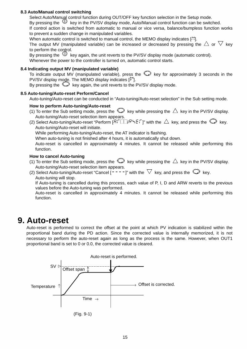
9. Auto-reset Auto-reset is performed to correct the offset at the point at which PV indication is stabilized within the proportional band during the PD action. Since the corrected value is internally memorized, it is not necessary to perform the auto-reset again as long as the process is the same. However, when OUT1 proportional band is set to 0 or 0.0, the corrected value is cleared.
(Fig. 9-1)
Auto-reset is performed.
Offset is corrected.
Offset span SV
Temperature
Time
16
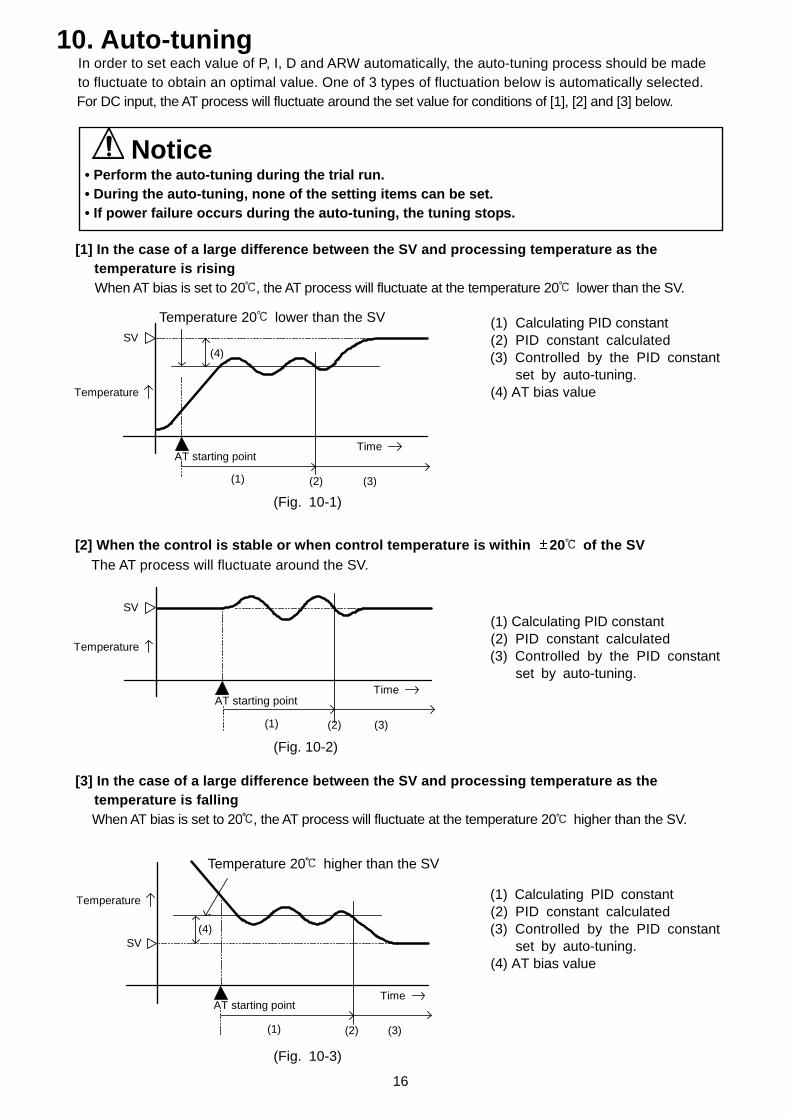
10. Auto-tuning In order to set each value of P, I, D and ARW automatically, the auto-tuning process should be made to fluctuate to obtain an optimal value. One of 3 types of fluctuation below is automatically selected. For DC input, the AT process will fluctuate around the set value for conditions of [1], [2] and [3] below.
Notice • Perform the auto-tuning during the trial run. • During the auto-tuning, none of the setting items can be set. • If power failure occurs during the auto-tuning, the tuning stops.
[1] In the case of a large difference between the SV and processing temperature as the temperature is rising When AT bias is set to 20 , the AT process will fluctuate at the temperature 20 lower than the SV.
(1) Calculating PID constant (2) PID constant calculated
(3) Controlled by the PID constant set by auto-tuning.
(4) AT bias value
(Fig. 10-1)
[2] When the control is stable or when control temperature is within 20 of the SV
The AT process will fluctuate around the SV.
(1) Calculating PID constant (2) PID constant calculated
(3) Controlled by the PID constant set by auto-tuning. (Fig. 10-2)
[3] In the case of a large difference between the SV and processing temperature as the
temperature is falling When AT bias is set to 20 , the AT process will fluctuate at the temperature 20 higher than the SV.
(1) Calculating PID constant
(2) PID constant calculated (3) Controlled by the PID constant set by auto-tuning.
(4) AT bias value
(Fig. 10-3)
(1) (2) (3)
(4)
AT starting point
SV
Temperature
Time
AT starting point
(1) (2) (3)
Temperature
SV
Time
AT starting point
(1) (2) (3)
(4)
Temperature
SV
Time
Temperature 20 higher than the SV
Temperature 20 lower than the SV
17
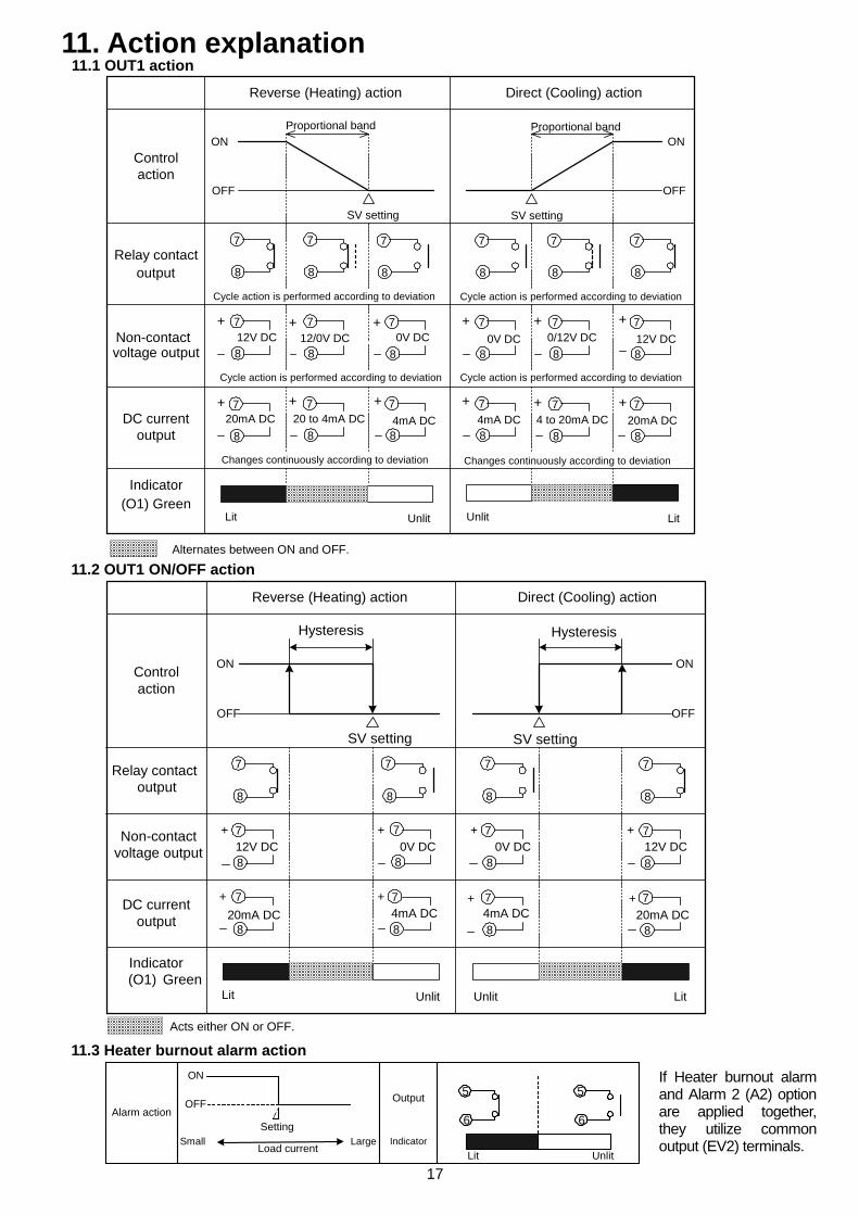
11. Action explanation 11.1 OUT1 action
11.2 OUT1 ON/OFF action
11.3 Heater burnout alarm action
Alternates between ON and OFF.
Reverse (Heating) action Direct (Cooling) action
Controlaction
Cycle action is performed according to deviation
Relay contactoutput
Non-contactvoltage output
Changes continuously according to deviation
DC currentoutput
Indicator(O1) Green
Lit Unlit
ON
OFF
SV setting
Proportional bandON
OFF
0V DC 0/12V DC12V DC+
20mA DC 20 to 4mA DC 4 to 20mA DC
Proportional band
Lit
0V DC 12V DC12/0V DC
20mA DC4mA DC
Cycle action is performed according to deviation
Cycle action is performed according to deviation Cycle action is performed according to deviation
Changes continuously according to deviation
+ + + + +
++++++
Unlit
4mA DC
8
7
8
7
8
7
8
7
8
7
8
7
8
7
8
7
8
7
8
7
8
7
8
7
8
7
8
7
8
7
8
7
8
7
8
7
SV setting
Acts either ON or OFF.
Reverse (Heating) action Direct (Cooling) action
Controlaction
Relay contactoutput
Non-contactvoltage output
DC currentoutput
Indicator(O1) Green
0V DC12V DC+
4mA DC
LitUnlit
ON
OFF
SV setting
ON
OFF
Hysteresis Hysteresis
0V DC 12V DC
4mA DC 20mA DC
UnlitLit
20mA DC
+
+ +
+
+
+
+
8
7
8
7
8
7
8
7
8
7
8
7
8
7
8
7
8
7
8
7
8
7
8
7
SV setting
Alarm action
ON
OFF
Setting
Load currentLargeSmall
Output
IndicatorUnlitLit
5
6
5
6
If Heater burnout alarm and Alarm 2 (A2) option are applied together,they utilize common output (EV2) terminals.
18
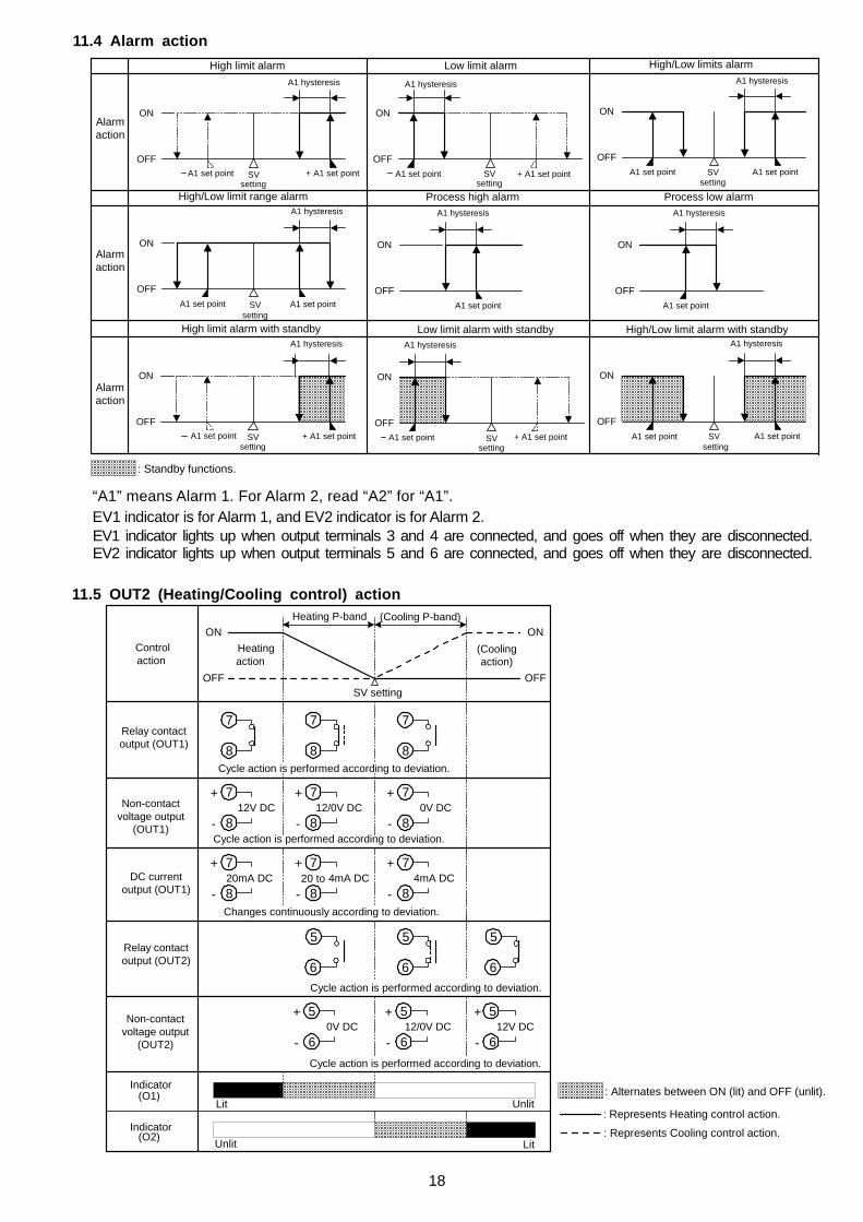
11.4 Alarm action
“A1” means Alarm 1. For Alarm 2, read “A2” for “A1”. EV1 indicator is for Alarm 1, and EV2 indicator is for Alarm 2. EV1 indicator lights up when output terminals 3 and 4 are connected, and goes off when they are disconnected. EV2 indicator lights up when output terminals 5 and 6 are connected, and goes off when they are disconnected.
11.5 OUT2 (Heating/Cooling control) action
: Alternates between ON (lit) and OFF (unlit).
: Represents Heating control action.
: Represents Cooling control action.
Controlaction
Heating P-band (Cooling P-band)
Heatingaction
(Coolingaction)
Relay contactoutput (OUT2)
Non-contactvoltage output
(OUT1)
Changes continuously according to deviation.
DC currentoutput (OUT1)
20 to
Cycle action is performed according to deviation.
OFF
ON
SV settingOFF
ON
888
777
(O1)
7+
8-12V DC
7+
8-12/0V DC
7+
8-0V DC
7+
8-20mA DC
7+
8-4mA DC
7+
8-4mA DC
5+
6-12V DC
5+
6-0V DC
5+
6-12/0V DC
Non-contactvoltage output
(OUT2)
Relay contactoutput (OUT1)
Indicator
(O2)Indicator
Unlit
LitUnlit
Lit
Cycle action is performed according to deviation.
Cycle action is performed according to deviation.
555
666Cycle action is performed according to deviation.
High limit alarm High/Low limits alarmLow limit alarm
Alarmaction
Alarmaction
Alarmaction
High/Low limit range alarm Process high alarm Process low alarm
High limit alarm with standby High/Low limit alarm with standbyLow limit alarm with standby
OFF
ON
A1 hysteresis
SVsetting
+ A1 set pointA1 set point
OFF
ON
A1 hysteresis
SVsetting
+ A1 set pointA1 set point
OFF
ON
A1 hysteresis
A1 set pointSVsetting
A1 set point
OFF
ON
A1 hysteresis
A1 set point SVsetting
OFF
ON
A1 hysteresis
A1 set point
OFF
ON
A1 hysteresis
A1 set point SVsetting
+ A1 set point
OFF
ON
A1 hysteresis
A1 set point SVsetting
A1 set point
SVsetting
OFF
ON
A1 hysteresis
A1 set pointA1 set point
OFF
ON
A1 hysteresis
A1 set point
+ A1 set point
: Standby functions.
19
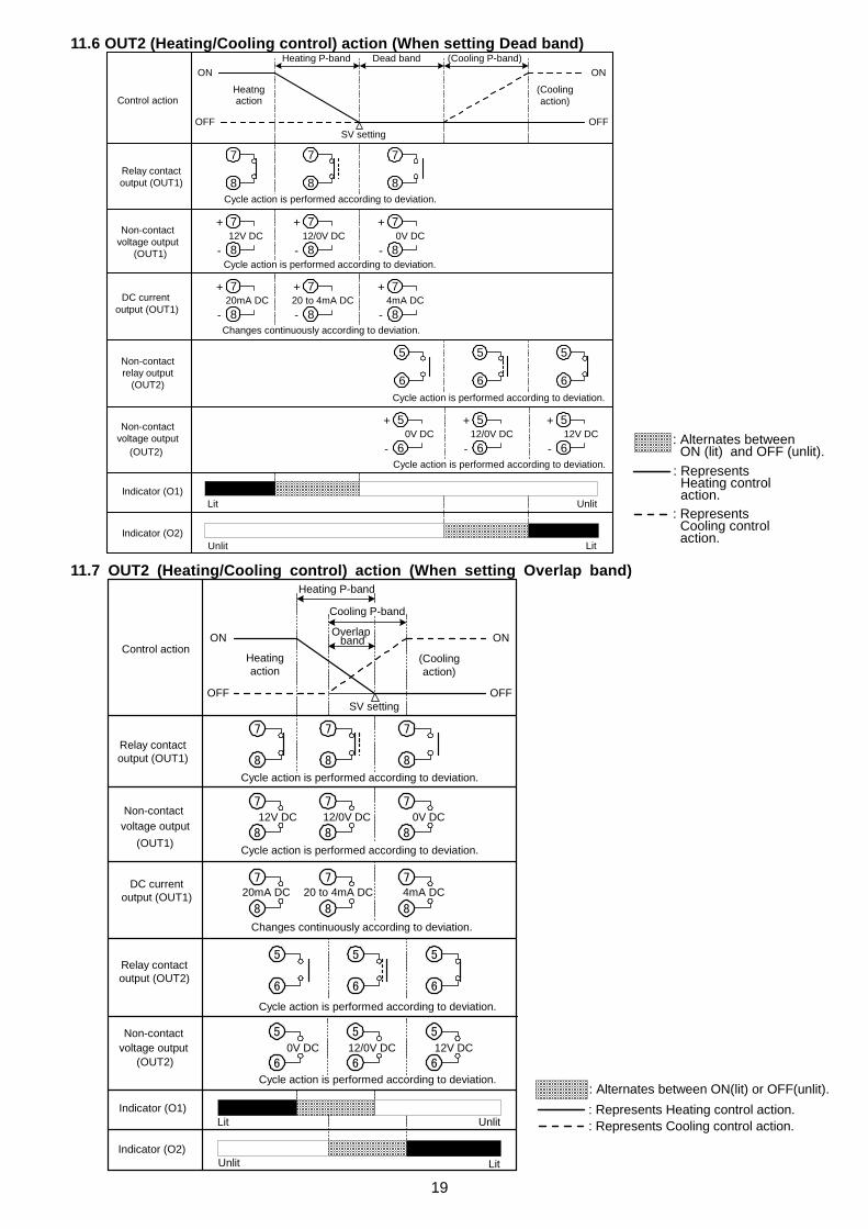
11.6 OUT2 (Heating/Cooling control) action (When setting Dead band) 11.7 OUT2 (Heating/Cooling control) action (When setting Overlap band)
: Alternates between ON(lit) or OFF(unlit).: Represents Heating control action.: Represents Cooling control action.
: Alternates between ON (lit) and OFF (unlit).: Represents Heating control action.: Represents Cooling control action.
Heating P-band Dead band (Cooling P-band)
Control action(Coolingaction)
Heatngaction
Cycle action is performed according to deviation.
Relay contactoutput (OUT1)
Non-contactvoltage output
(OUT1)
Changes continuously according to deviation.
DC current output (OUT1)
Non-contactrelay output
(OUT2)
Unlit
Indicator (O1)Lit
OFF
ON
SV settingOFF
ON
7+
8-12V DC
7+
8-12/0V DC
7+
8-0V DC
7+
8-20mA DC
7+
8-20 to 4mA DC
7+
8-4mA DC
888
777
6 6 6
5 5 5
(OUT2)
5+
6-12V DC
5+
6-12/0V DC
5+
6-0V DC
Indicator (O2)
Cycle action is performed according to deviation.
Cycle action is performed according to deviation.
Cycle action is performed according to deviation.
Lit
Unlit
Non-contactvoltage output
OFF
ON
OFF
ON
888
777
5 5 5
6 6 6
Indicator (O1)
(OUT2)
5 5 5
6 6 6
(OUT1)888
777
888
777
12V DC 12/0V DC 0V DC
20mA DC 20 to 4mA DC 4mA DC
0V DC 12/0V DC 12V DC
Heating P-band
Cooling P-band
Non-contactvoltage output
Control action
SV setting
Heatingaction
(Coolingaction)
Relay contactoutput (OUT1)
Lit
Lit
Unlit
Unlit
DC currentoutput (OUT1)
Relay contactoutput (OUT2)
Non-contactvoltage output
Indicator (O2)
Cycle action is performed according to deviation.
Cycle action is performed according to deviation.
Changes continuously according to deviation.
Cycle action is performed according to deviation.
Cycle action is performed according to deviation.
Overlap band
20
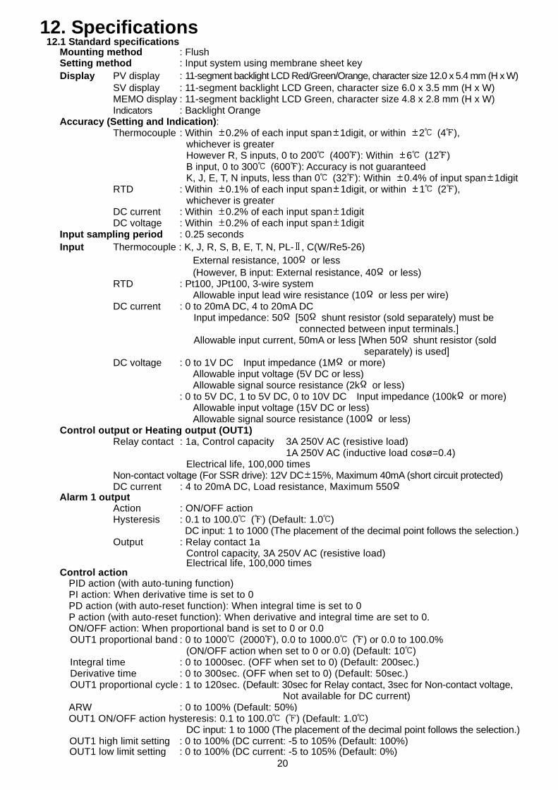
12. Specifications 12.1 Standard specifications
Mounting method : Flush Setting method : Input system using membrane sheet key Display PV display : 11-segment backlight LCD Red/Green/Orange, character size 12.0 x 5.4 mm (H x W)
SV display : 11-segment backlight LCD Green, character size 6.0 x 3.5 mm (H x W) MEMO display : 11-segment backlight LCD Green, character size 4.8 x 2.8 mm (H x W) Indicators : Backlight Orange
Accuracy (Setting and Indication): Thermocouple : Within 0.2% of each input span 1digit, or within 2 (4 ), whichever is greater However R, S inputs, 0 to 200 (400 ): Within 6 (12 ) B input, 0 to 300 (600 ): Accuracy is not guaranteed K, J, E, T, N inputs, less than 0 (32 ): Within 0.4% of input span 1digit RTD : Within 0.1% of each input span 1digit, or within 1 (2 ),
whichever is greater DC current : Within 0.2% of each input span 1digit DC voltage : Within 0.2% of each input span 1digit
Input sampling period : 0.25 seconds Input Thermocouple : K, J, R, S, B, E, T, N, PL- , C(W/Re5-26)
External resistance, 100 or less (However, B input: External resistance, 40 or less) RTD : Pt100, JPt100, 3-wire system Allowable input lead wire resistance (10 or less per wire) DC current : 0 to 20mA DC, 4 to 20mA DC Input impedance: 50 [50 shunt resistor (sold separately) must be connected between input terminals.] Allowable input current, 50mA or less [When 50 shunt resistor (sold separately) is used] DC voltage : 0 to 1V DC Input impedance (1M or more) Allowable input voltage (5V DC or less) Allowable signal source resistance (2k or less) : 0 to 5V DC, 1 to 5V DC, 0 to 10V DC Input impedance (100k or more) Allowable input voltage (15V DC or less) Allowable signal source resistance (100 or less)
Control output or Heating output (OUT1) Relay contact : 1a, Control capacity 3A 250V AC (resistive load) 1A 250V AC (inductive load cosø=0.4) Electrical life, 100,000 times Non-contact voltage (For SSR drive): 12V DC 15%, Maximum 40mA (short circuit protected) DC current : 4 to 20mA DC, Load resistance, Maximum 550
Alarm 1 output Action : ON/OFF action
Hysteresis : 0.1 to 100.0 ( ) (Default: 1.0 ) DC input: 1 to 1000 (The placement of the decimal point follows the selection.)
Output : Relay contact 1a Control capacity, 3A 250V AC (resistive load) Electrical life, 100,000 times
Control action PID action (with auto-tuning function) PI action: When derivative time is set to 0 PD action (with auto-reset function): When integral time is set to 0 P action (with auto-reset function): When derivative and integral time are set to 0. ON/OFF action: When proportional band is set to 0 or 0.0 OUT1 proportional band : 0 to 1000 (2000 ), 0.0 to 1000.0 ( ) or 0.0 to 100.0% (ON/OFF action when set to 0 or 0.0) (Default: 10 ) Integral time : 0 to 1000sec. (OFF when set to 0) (Default: 200sec.) Derivative time : 0 to 300sec. (OFF when set to 0) (Default: 50sec.) OUT1 proportional cycle : 1 to 120sec. (Default: 30sec for Relay contact, 3sec for Non-contact voltage, Not available for DC current) ARW : 0 to 100% (Default: 50%) OUT1 ON/OFF action hysteresis: 0.1 to 100.0 ( ) (Default: 1.0 ) DC input: 1 to 1000 (The placement of the decimal point follows the selection.)
OUT1 high limit setting : 0 to 100% (DC current: -5 to 105% (Default: 100%) OUT1 low limit setting : 0 to 100% (DC current: -5 to 105% (Default: 0%)
21
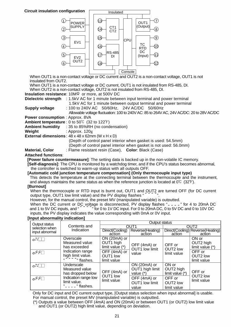
Circuit insulation configuration
When OUT1 is a non-contact voltage or DC current and OUT2 is a non-contact voltage, OUT1 is not insulated from OUT2. When OUT1 is a non-contact voltage or DC current, OUT1 is not insulated from RS-485, DI. When OUT2 is a non-contact voltage, OUT2 is not insulated from RS-485, DI.
Insulation resistance: 10M or more, at 500V DC Dielectric strength : 1.5kV AC for 1 minute between input terminal and power terminal 1.5kV AC for 1 minute between output terminal and power terminal Supply voltage : 100 to 240V AC 50/60Hz, 24V AC/DC 50/60Hz Allowable voltage fluctuation: 100 to 240V AC: 85 to 264V AC, 24V AC/DC: 20 to 28V AC/DC Power consumption : Approx. 8VA Ambient temperature : 0 to 50 (32 to 122 ) Ambient humidity : 35 to 85%RH (no condensation) Weight : Approx. 120g External dimensions : 48 x 48 x 62mm (W x H x D)
(Depth of control panel interior when gasket is used: 54.5mm) (Depth of control panel interior when gasket is not used: 56.0mm)
Material, Color : Flame resistant resin (Case), Color: Black (Case) Attached functions:
[Power failure countermeasure]: The setting data is backed up in the non-volatile IC memory. [Self-diagnosis]: The CPU is monitored by a watchdog timer, and if the CPU’s status becomes abnormal,
the controller is switched to warm-up status with all outputs OFF. [Automatic cold junction temperature compensation] (Only thermocouple input type)
This detects the temperature at the connecting terminal between the thermocouple and the instrument, and always maintains the same status as when the reference junction is located at 0 (32 ).
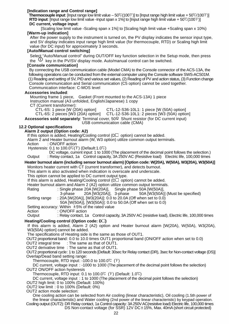
[Burnout] When the thermocouple or RTD input is burnt out, OUT1 and OUT2 are turned OFF (for DC current output type, OUT1 low limit value) and the PV display flashes “ ”. However, for the manual control, the preset MV (manipulated variable) is outputted. When the DC current or DC voltage is disconnected, PV display flashes “ ” for 4 to 20mA DC and 1 to 5V DC inputs, and “ ” for 0 to 1V DC input. For 0 to 20mA DC, 0 to 5V DC and 0 to 10V DC inputs, the PV display indicates the value corresponding with 0mA or 0V input.
[Input abnormality indication] Output status
OUT1 OUT2 Output status selection when input abnormal
Contents and Indication Direct(Cooling)
action Reverse(Heating)
action Direct(Cooling)
action Reverse(Heating)
action ON (20mA) or
OUT1 high limit value (*)
ON or OUT2 high limit value (*)
Overscale Measured value has exceeded Indication range high limit value. " " flashes.
OFF (4mA) or OUT1 low limit value
OFF (4mA) or OUT1 low limit value
OFF or OUT2 low limit value OFF or
OUT2 low limit value
ON (20mA) or OUT1 high limit value (*)
ON or OUT2 high limit value (*)
Underscale Measured value has dropped below Indication range low limit value. " " flashes.
OFF (4mA) or OUT1 low limit value OFF (4mA) or
OUT1 low limit value
OFF or OUT2 low limit value
OFF or OUT2 low limit value
Only for DC input and DC current output type, [Output status selection when input abnormal] is usable. For manual control, the preset MV (manipulated variable) is outputted. (*) Outputs a value between OFF (4mA) and ON (20mA) or between OUT1 (or OUT2) low limit value
and OUT1 (or OUT2) high limit value, depending on deviation.
EV1
EV2OUT2
RS-485DI
CT1CT2
POWERSUPPLY
CPU
OUT1(Output)
TCRTDDC
1
3
2
4
5
6
7
8
9
10
11
12
14
13
15
16
17
18
(Input)
Console
Insulated
22
[Indication range and Control range] Thermocouple input: [Input range low limit value – 50 (100 )] to [Input range high limit value + 50 (100 )] RTD input: [Input range low limit value -Input span x 1%] to [Input range high limit value + 50 (100 )] DC current, voltage input:
[Scaling low limit value -Scaling span x 1%] to [Scaling high limit value +Scaling span x 10%) [Warm-up indication]
After the power supply to the instrument is turned on, the PV display indicates the sensor input type, and SV display indicates input range high limit value (for thermocouple, RTD) or Scaling high limit value (for DC input) for approximately 3 seconds.
[Auto/Manual control switching] Select “Auto/Manual control” during OUT/OFF key function selection in the Setup mode, then press the key in the PV/SV display mode. Auto/manual control can be switched.
[Console communication] By connecting the USB communication cable (Model CMA) to the Console connector of the ACS-13A, the following operations can be conducted from the external computer using the Console software SWS-ACS01M. (1) Reading and setting of SV, PID and various set values, (2) Reading of PV and action status, (3) Function change Console communication and Serial communication (C5 option) cannot be used together. Communication interface: C-MOS level
Accessories included: Mounting frame 1 piece, Gasket (Front mounted to the ACS-13A) 1 piece Instruction manual (A3 unfolded, English/Japanese) 1 copy CT (Current transformer):
CTL-6S: 1 piece [W (20A) option] CTL-12-S36-10L1: 1 piece [W (50A) option] CTL-6S: 2 pieces [W3 (20A) option] CTL-12-S36-10L1: 2 pieces [W3 (50A) option]
Accessories sold separately: Terminal cover, 50 Shunt resistor (for DC current input) USB communication cable (CMA)
12.2 Optional specifications Alarm 2 output (Option code: A2)
If this option is added, Heating/Cooling control (D option) cannot be added. Alarm 2 and Heater burnout alarm (W, W3 option) utilize common output terminals. Action : ON/OFF action Hysteresis: 0.1 to 100.0 ( ) (Default:1.0 ) DC voltage, current input: 1 to 1000 (The placement of the decimal point follows the selection.) Output : Relay contact, 1a Control capacity, 3A 250V AC (Resistive load) Electric life, 100,000 times
Heater burnout alarm (including sensor burnout alarm) [Option code: W(20A), W(50A), W3(20A), W3(50A)] Monitors heater current with CT (current transformer), and detects burnout. This alarm is also activated when indication is overscale and underscale. This option cannot be applied to DC current output type. If this alarm is added, Heating/Cooling control (D option) cannot be added. Heater burnout alarm and Alarm 2 (A2) option utilize common output terminals. Rating : Single phase 20A [W(20A)], Single phase 50A [W(50A)], 3-phase 20A [W3(20A)], 3-phase 50A [W3(50A)] (Must be specified) Setting range : 20A [W(20A)], [W3(20A)]: 0.0 to 20.0A (Off when set to 0.0) 50A [W(50A)], [W3(50A)]: 0.0 to 50.0A (Off when set to 0.0) Setting accuracy : Within 5% of the rated value Action : ON/OFF action Output : Relay contact, 1a Control capacity, 3A 250V AC (resistive load), Electric life, 100,000 times
Heating/Cooling control (Option code: D ) If this alarm is added, Alarm 2 (A2) option and Heater burnout alarm [W(20A), W(50A), W3(20A), W3(50A) option] cannot be added. The specifications of Heating side is the same as those of OUT1. OUT2 proportional band : 0.0 to 10.0 times OUT1 proportional band (ON/OFF action when set to 0.0) OUT2 integral time : The same as that of OUT1. OUT2 derivative time : The same as that of OUT1. OUT2 proportional cycle : 1 to 120 seconds [Default: 30sec for Relay contact (DR), 3sec for Non-contact voltage (DS)] Overlap/Dead band setting range:
Thermocouple, RTD input : -100.0 to 100.0 ( ) DC current, voltage input : -1000 to 1000 (The placement of the decimal point follows the selection)
OUT2 ON/OFF action hysteresis Thermocouple, RTD input : 0.1 to 100.0 ( ) (Default: 1.0 ) DC current, voltage input : 1 to 1000 (The placement of the decimal point follows the selection)
OUT2 high limit : 0 to 100% (Default: 100%) OUT2 low limit : 0 to 100% (Default: 0%) OUT2 action mode selection:
One cooling action can be selected from Air cooling (linear characteristic), Oil cooling (1.5th power of the linear characteristic) and Water cooling (2nd power of the linear characteristic) by keypad operation.
Cooling output (OUT2): DR Relay contact, 1a Control capacity: 3A 250V AC(resistive load) Electric life, 100,000 times DS Non-contact voltage (for SSR) 12V DC 15%, Max. 40mA (short circuit protected)
23
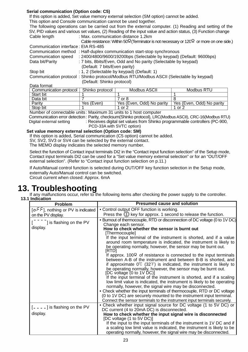
Serial communication (Option code: C5) If this option is added, Set value memory external selection (SM option) cannot be added. This option and Console communication cannot be used together. The following operations can be carried out from the external computer. (1) Reading and setting of the SV, PID values and various set values, (2) Reading of the input value and action status, (3) Function change Cable length : Max. communication distance 1.2km Cable resistance: Within 50 (Terminator is not necessary or 120 or more on one side.) Communication interface : EIA RS-485 Communication method : Half-duplex communication start-stop synchronous Communication speed : 2400/4800/9600/19200bps (Selectable by keypad) (Default: 9600bps) Data bit/Parity : 7 bits, 8bits/Even, Odd and No parity (Selectable by keypad)
(Default: 7 bits/Even parity) Stop bit : 1, 2 (Selectable by keypad) (Default: 1) Communication protocol : Shinko protocol/Modbus RTU/Modbus ASCII (Selectable by keypad) (Default: Shinko protocol) Data format Communication protocol Shinko protocol Modbus ASCII Modbus RTU Start bit 1 1 1 Data bit 7 7 or 8 8 Parity Yes (Even) Yes (Even, Odd) No parity Yes (Even, Odd) No parity Stop bit 1 1 or 2 1 or 2
Number of connectable units : Maximum 31 units to 1 host computer Communication error detection : Parity, checksum(Shinko protocol), LRC(Modbus ASCII), CRC-16(Modbus RTU) Digital external setting : Receives digital set values from Shinko programmable controllers (PC-900, PCD-33A with SVTC option)
Set value memory external selection (Option code: SM) If this option is added, Serial communication (C5 option) cannot be added. SV, SV2, SV3 or SV4 can be selected by the external contact. The MEMO display indicates the selected memory number. Select the function of Contact input terminals DI2 in the “Contact input function selection” of the Setup mode, Contact input terminals DI2 can be used for a “Set value memory external selection” or for an “OUT/OFF external selection”. (Refer to “Contact input function selection on p.11.) If Auto/Manual control function is selected during OUT/OFF key function selection in the Setup mode, externally Auto/Manual control can be switched. Circuit current when closed: Approx. 6mA
13. Troubleshooting If any malfunctions occur, refer to the following items after checking the power supply to the controller.
13.1 Indication Problem Presumed cause and solution
[ ], nothing or PV is indicated on the PV display.
• Control output OFF function is working. Press the key for approx. 1 second to release the function.
[ ] is flashing on the PV display.
• Burnout of thermocouple, RTD or disconnection of DC voltage (0 to 1V DC)Change each sensor. How to check whether the sensor is burnt out [Thermocouple]
If the input terminal of the instrument is shorted, and if a value around room temperature is indicated, the instrument is likely to be operating normally, however, the sensor may be burnt out.
[RTD] If approx. 100 of resistance is connected to the input terminals between A-B of the instrument and between B-B is shorted, and if approximate 0 (32 ) is indicated, the instrument is likely to
be operating normally, however, the sensor may be burnt out. [DC voltage (0 to 1V DC)]
If the input terminal of the instrument is shorted, and if a scalinglow limit value is indicated, the instrument is likely to be operatingnormally, however, the signal wire may be disconnected.
• Check whether the input terminals of thermocouple, RTD or DC voltage (0 to 1V DC) are securely mounted to the instrument input terminal.
Connect the sensor terminals to the instrument input terminals securely. [ ] is flashing on the PV display.
• Check whether input signal source for DC voltage (1 to 5V DC) or DC current (4 to 20mA DC) is disconnected.
How to check whether the input signal wire is disconnected [DC voltage (1 to 5V DC)]
If the input to the input terminals of the instrument is 1V DC and ifa scaling low limit value is indicated, the instrument is likely to beoperating normally, however, the signal wire may be disconnected.
24
[DC current (4 to 20mA DC)] If the input to the input terminals of the instrument is 4mA DC andif a scaling low limit value is indicated, the instrument is likely to beoperating normally, however, the signal wire may be disconnected.
• Check whether input signal wire for DC voltage (1 to 5V DC) or DC current (4 to 20mA DC) is securely connected to the instrument input terminals.• Check if polarity of thermocouple or compensating lead wire is correct. • Check whether codes (A, B, B) of RTD agree with the instrument terminals.
The PV display keeps indicating the value which was set during Scaling low limit setting.
• Check whether the input signal source for DC voltage (0 to 5V DC, 0 to 10V DC) and DC current (0 to 20mA DC) is disconnected. How to check whether the input signal wire is disconnected [DC voltage (0 to 5V DC, 0 to 10V DC)]
If the input to the input terminals of the instrument is 1V DC and ifthe value corresponding to 1V DC is indicated, the instrument islikely to be operating normally, however, the signal wire may bedisconnected.
[DC current (0 to 20mA DC)] If the input to the input terminals of the instrument is 1mA DC andif the value corresponding to 1mA DC is indicated, the instrumentis likely to be operating normally, however, the signal wire may bedisconnected.
• Check whether the input lead wire terminals for DC voltage (0 to 5VDC, 0 to 10V DC) or DC current (0 to 20mA DC) are securelymounted to the instrument input terminals.
The indication of PV display is abnormal or unstable.
• Check whether sensor input or temperature unit ( or ) is correct.Select the sensor input and temperature unit ( or ) properly.
• Sensor correcting value is unsuitable. Set it to a suitable value. • Check whether the specification of the sensor is correct. • AC leaks into the sensor circuit. Use an ungrounded type sensor. • There may be equipment that interferes with or makes noise near the controller. Keep equipment that interferes with or makes noise away from thecontroller.
[ ] is indicated on the PV display.
• Internal memory is defective. Contact our agency or us.
13.2 Key operation Problem Presumed cause and solution
• Unable to set the SV, P, I, D, proportional cycle or alarm setting
• The values do not change by , keys.
• Set value lock (Lock 1 or Lock 2) is designated. Release the lock in the “Set value lock selection”.
• Auto-tuning or auto-reset is performing. In the case of auto-tuning, cancel auto-tuning. It takes approximately 4 minutes until auto-reset is finished.
The setting indication does not change in the input range even if the , keys are pressed, and new values are unable to be set.
• Scaling high or low limit value in the Setup mode may be set at thepoint where the value does not change. Set it to a suitable value while in the Setup mode.
13.3 Control Problem Presumed cause and solution
Temperature does not rise. • Sensor is out of order. Replace the sensor. • Check whether the Sensor or control output terminals are securely
mounted to the instrument input terminals. Ensure that the sensor or control output terminals are mounted tothe instrument input terminals securely.
• Check whether the wiring of sensor or control output terminals is correct. The control output remains in an ON status.
• OUT1 or OUT2 low limit value is set to 100% or higher in Setup mode. Set it to a suitable value.
The control output remains in an OFF status.
• OUT1 or OUT2 high limit value is set to 0% or less in Setup mode. Set it to a suitable value.
• For all other malfunctions, please contact our main office or dealers.
SHINKO TECHNOS CO.,LTD.OVERSEAS DIVISION
:::
Reg. OfficeURLE-mail
2-5-1, Senbahigashi, Minoo, Osaka, Japanhttp://[email protected]
Tel :Fax:
81-72-727-610081-72-727-7006