Embed Size (px)
Citation preview

Version 11/2019
ECL15B-SMS-001-EN
xyz
WARNING
Do not use the electric truck before reading
and understanding these operating
instructions.
NOTE:
• Please check the designation of your
present type at the last page of this
document as well as on the ID-plate.
• Keep for future reference.
INSTRUCTION HANDBOOK
Electric Stacker ECL15B

1
FORWARD
Before operating the electric stacker, read this ORIGINAL INSTRUCTION HANDBOOK carefully and
understand the usage of the truck completely. Improper operation of the truck may create a danger
situation. This handbook describes the usage of different electric stackers. When operating and
servicing the truck, make sure, that it applies to your type.
Keep this handbook for future reference. If this or the warning/caution labels are damaged or got lost,
please contact your local dealer for replacement.
This truck complies with the requirements according to EN 3691-1 (Industrial trucks - safety
requirements and verification, part 1), EN 12895 (Industrial trucks - electromagnetic compatibility),
EN 12053 (Safety of industrial trucks- test methods for measuring noise emissions), EN 1175-1
(Industrial truck safety – electrical requirements), assumed the truck is used according to the described
purpose.
The noise level for this machine is < 70 dB(A) according to EN 12053.
ATTENTION:
• Environmentally hazardous waste, such as batteries, oil and electronics, will have a
negative effect on the environment or health, if handled incorrectly.
• The waste packages should be sorted and put into solid dustbins according to the
materials and be collected disposal by local special environment protection bureau. To
avoid pollution, it’s forbidden to throw away the wastes randomly.
• To avoid leaking during the use of the products, the user should prepare some
absorbable materials (scraps of wooden or dry duster cloth) to absorb the leaking oil in
time. To avoid second pollution to the environment, the used absorbable materials
should be handed in to special departments in terms of local authorities.
• Our products are subject to ongoing developments. The information written in this
handbook is provided as reference for operating and servicing the stacker and may vary
in terms of description of particular features of the truck.
NOTE: On this manual, the left sign means warning and danger, which can lead to
death or serious injury if not followed.
Copyright
The copyright remains with the company, mentioned on the CE- certificate at the end of this document or,
if sold within the USA, with the company, mentioned on the company sticker.

2
TABLE OF CONTENTS
1. CORRECT APPLICATION ................................................................................................................. 4
2. DESCRIPTION OF THE STACKER ................................................................................................... 5
a. Overview of the main components ................................................................................................. 5
b. Main technical data ......................................................................................................................... 6
c. Description of the safety devices and warning labels (Europe and other, except USA) ................ 7
d. Identification plate ........................................................................................................................... 8
3. WARNINGS, RESIDUAL RISK AND SAFETY INSTRUCTIONS .................................................... 10
4. COMMISSIONING, TRANSPORTING, DECOMMISSIONING ........................................................ 11
a. Commissioning .............................................................................................................................. 11
b. Lifting/ transportation ..................................................................................................................... 11
c. Decommissioning .......................................................................................................................... 12
5. DAILY INSPECTION......................................................................................................................... 12
6. OPERATION INSTRUCTIONS ........................................................................................................ 13
a. Parking .......................................................................................................................................... 13
b. Residual lift diagram ..................................................................................................................... 13
c. Lifting ............................................................................................................................................. 14
d. Lowering ........................................................................................................................................ 14
e. Travelling ....................................................................................................................................... 14
f. Steering ......................................................................................................................................... 15
g. Braking .......................................................................................................................................... 15
h. Malfunctions .................................................................................................................................. 15
i. Emergency .................................................................................................................................... 15
7. BATTERY CHARGING AND REPLACEMENT ................................................................................ 16
a. Replacement ................................................................................................................................. 16
b. Battery Indicator ............................................................................................................................ 17
c. Charging ........................................................................................................................................ 18
8. REGULAR MAINTENANCE ............................................................................................................. 19
a. Maintenance checklist................................................................................................................... 19
b. Lubricating points .......................................................................................................................... 20
c. Check and refill hydraulic oil ......................................................................................................... 20
d. Checking electrical fuses .............................................................................................................. 21
e. Removing, reattaching guarding ................................................................................................... 21

3
9. TROUBLE SHOOTING .................................................................................................................... 22
10. WIRING/ CIRCUIT DIAGRAM .......................................................................................................... 23
a. Electrical circuit diagram ............................................................................................................... 23
b. Hydraulic circuit ............................................................................................................................. 24
11. DECLARATION OF CONFORMITY (valid, if sold within the EU) .................................................... 25

4
1. CORRECT APPLICATION
It is only allowed to use this electric stacker according to this instruction handbook.
The trucks described in this handbook are self-propelled pedestrian controlled electric power stackers,
with electrically powered lifting function. The trucks are designed for stacking operations in dedicated
racking by lifting and lowering the palletized loads up to the desired lifting heights.
A wrong usage can cause human injuries or can damage equipment.
The operator/ the operating company has to ensure the correct usage and has to ensure, that this truck
is used only by staff, which is trained and authorized to use this truck.
The truck has to be used on substantially firm, smooth, prepared, level and adequate surfaces. The truck
is intended to be used for indoor applications with ambient temperatures between +5C and + 40C and
for various transportation applications without crossing permanent obstacles or potholes. The work on
ramps is allowed if ramp is not exceeding the allowed angle. While operating, the load must be placed
approximately on the longitudinal centre plane of the truck.
Lifting or transporting people is forbidden.
If used on tail lifts or loading ramps, please ensure that these are used correctly according to the
operating instructions.
The capacity is marked on capacity sticker as well on the Identification plate. The operator has to
consider the warnings and safety instructions.
Operating lighting must be minimum 50 Lux.
Modification
No modifications or alterations to this stacker which may affect, for example, capacity, stability or safety
requirements of the truck, shall be made without the prior written approval of the original truck
manufacturer, its authorized representative, or a successor thereof. This includes changes affecting, for
example braking, steering, visibility and the addition of removable attachments. When the manufacturer
or its successor approve a modification or alteration, they shall also make and approve appropriate
changes to capacity plate, decals, tags and operation and maintenance handbooks.
Only in the event that the truck manufacturer is no longer in business and there is no successor in the interest to the business, may the
user arrange for a modification or alteration to a powered industrial truck, provided, however, that the user:
a) arranges for the modification or alteration to be designed, tested and implemented by an engineer(s) expert in industrial trucks and
their safety,
b) maintains a permanent record of the design, test(s) and implementation of the modification or alteration,
c) approves and makes appropriate changes to the capacity plate(s), decals, tags and instruction handbook, and
d) affixes a permanent and readily visible label to the truck stating the manner in which the truck has been modified or altered, together
with the date of the modification or alteration and the name and address of the organization that accomplished those tasks.
By not observing these instructions, the warranty becomes void.

5
Fig. 1: Overview main components
2. DESCRIPTION OF THE STACKER
a. Overview of the main components
1. Motor cover
2. Driving wheel
3. Steering wheel
4. Charging LED
5. Charging cable
6. Emergency button
7. Belly button
8. Accelerator
9. Tiller
10. Main cover
11. Discharge indicator and charging indicating
LED
12. Key switch
13. Chassis
14. Fork carriage
15. Protective board
16. Load roller
17. Hydraulic system

6
b. Main technical data
Table1: Main technical data for standard version
Fig. 2: Technical data
Type sheet for industrial truck acc. to VDI 2198
Ge
ne
ral
da
ta
1.2 Manufacturer`s type designation ECL15B
1600 3600
1.3 Power (battery ,diesel, petrol, gas, manual) Battery
1.4 Operator type Pedestrian
1.5 Load Capacity / rated load Q(t) 1.5
1.6 Load centre distance C(mm) 600
1.8 Load distance ,centre of drive axle to fork X(mm) 770
1.9 Wheelbase Y(mm) 1258 1283
We
ig
ht
2.1 Service weight kg 641 782
2.2 Axle loading, laden front/rear kg 677/1464 722/1560
2.3 Axle loading, unladen front/rear kg 446/195 544/238
Tir
es
, c
ha
ss
is
3.1 Tires Polyurethane (PU)
3.2 Tire size, front x w (mm) Ф210×70
3.3 Tire size, rear x w (mm) Ф80×70
3.4 Additional wheels(dimensions) x w (mm) Ф100×50
3.5 Wheels, number front/rear(x=driven wheels) 1x+1/4
3.6 Track, front b10(mm) 557
3.7 Track, rear b11(mm) 410/525
Dim
en
sio
ns
4.2 Lowered mast height h1 (mm) 1978 2280
4.3 Free Lift height h2 (mm) 1510 78
4.4 Lift height h3 (mm) 1515 3515
4.5 Extended mast height h4 (mm)
1985 4005
4.9 Height of tiller in drive position min./ max. h14mm 710/1245
4.15 Height, lowered h13mm 85
4.19 Overall length l1(mm) 1806 1830
4.20 Length to face of forks l2(mm) 656 681
4.21 Overall width b1(mm) 820

7
4.22 Fork dimensions s/ e/ l(mm) 60/180/1150
4.25 Width across forks b5 (mm) 570/685
4.32 Ground clearance, centre of wheelbase m2(mm) 25
4.33 Aisle width for pallets 1000X1200 crossways Ast (mm) 2293 2317
4.34 Aisle width for pallets 800X1200 lengthways Ast (mm) 2237 2261
4.35 Turning radius Wa (mm) 1450 1474
Pe
rfo
rma
nc
e 5.1 Travel speed, laden/ unladen km/h 4.4/4.7
5.2 Lift speed, laden/ unladen m/s 0.105/0.17
5.3 Lowering speed, laden/ unladen m/s 0.126/0.126
5.8 Max. gradeability, laden/ unladen % 5/10
5.10 Service brake Electromagnetic
Mo
tor
6.1 Drive motor rating kW 0.75
6.2 Lift motor rating at S3 7.5% kW 2.2
6.3 Battery acc. to DIN 43531/35/36 A, B, C, no no
6.4 Battery voltage, nominal capacity K5 V/Ah 4x12/60
6.5 Battery weight kg 4x20
6.6 Energy consumption acc: to VDI cycle kWh/h 0.5
oth
er 8.1 Type of drive control DC
8.4 Sound level at driver’s ear acc. to EN 12053 db(A) <70
Type
Lowered mast
height
h1(mm)
Free Lift
height
h2(mm)
Lift
height
h3(mm)
Extended mast
height
h4(mm)
Max. mast height
h3+h13(mm)
One stage mast 2378 1910 1915 2385 2000
Two stage mast 1930 78 2815 3305 2900
2080 78 3115 3605 3200
c. Description of the safety devices and warning labels (Europe
and other, except USA)
A Crane hook label B Warning decal: Do not step under or on the forks C Residual lift capacity sticker D Sticker to read and follow these instructions E “No passengers” decal F Identification plate (ID-plate) P Never reach through
The truck has an emergency button (6) which stops all lifting-,
lowering-, driving- functions and engages the failsafe
electromagnetic brake when it is pushed. By pulling this button, the
truck can be operated after the controller checked the functions.
Before operating, insert the key and turn the switch (2) clockwise.
To prevent against unauthorized access, turn the key
anti-clockwise and remove it if you do not operate this truck The
truck is equipped with a safety (belly) button (7) which switches the driving function away from the
operator, if the truck travels towards the operator and the Fig.3: Safety and warning labels

8
tiller is in its operating zone. Follow also the instructions given on the decals. Replace the decals if they
are damaged or missing.
d. Identification plate
1 Designation, type
2 Serial number
3 Rated capacity in kg
4 Supply voltage in V
5 Own mass (self weight) in kg without battery
6 Name and address of manufacturer)
7 Battery weight minimum/ maximum
8 Nominal power in kW
9 Load center distance
10 Manufacturing date
11 Option
Fig. 4: Identification plate
1
2
4
5
3
7
If sold to the EU, here the
place of the CE marking
6
8
9
10
11

10
3. WARNINGS, RESIDUAL RISK AND SAFETY INSTRUCTIONS
DO NOT
• Put foot or hand under or into the lifting mechanism.
• Allow other person than the operator to stand in front of or behind the truck when it is
moving or lifting/lowering.
• Overload the truck.
• Put foot in front of the wheels, injury could result.
• Lift people. People could fall down and suffer severe injury.
• Push or pull loads; use drawbar
• Side or end load. Load must be distributed evenly on the forks.
• Use the truck with unstable, unbalanced not stable load.
• Use truck without manufacturer’s written consent.
• Lifted loads could become unstable at wind forces. In the case of wind forces do not
lift the load if there is any influence to the stability
• Do not use the truck without help if load is causing insufficient visibility. Operation
without help of additional people may result in crushes or injuries. Always make sure
the transportation of load is safe.
• Do not operate the truck with removed covers or the apron.
Watch difference in floor levels when driving. Load could fall down or the truck could get uncontrollable.
Keep watching the condition of load. Stop operating the truck if load becomes unstable.
Brake the truck and activate the emergency button (6) by pushing when sliding load on or off the truck. If
the truck has any malfunctions, follow chapter 8.
Practice maintenance work according to regular inspection. This truck is not designed to be water
resistant. Use the truck under dry condition. Prolonged continuous operation might cause damage of the
power pack. Stop operation if temperature of hydraulic oil is too high.
• When operating the electric stacker, the operator has to wear safety shoes.
• The truck is intended to be used for indoor applications with ambient temperatures
between +5C and + 40C.
• The operating lighting must be minimum 50 Lux.
• To prevent unintended sudden movements when not operating the truck (i.e. from
another person, etc.), press emergency switch (6) or press the X button of pin-code
panel.

11
4. COMMISSIONING, TRANSPORTING, DECOMMISSIONING
a. Commissioning
Table 2: Commissioning data
Type ECL15B/1600 ECL15B/3600
Commissioning weight [kg] 670 810
Dimensions [mm] 1600 3600
After receiving our new stacker or for re-commissioning you have to do following before (firstly)
operating the truck:
• Check if are all parts included and not damaged
• Make sure the tiller is assembled correctly (electrical socket is connected and fixed with two plastic
clamps, circlip of the axle is installed)
• Check that battery is charged (follow chapter 8)
• Do the work according to the daily inspections as well as functional checks.
b. Lifting/ transportation
For transporting, remove the load, lower the forks to the lowest position and fix the truck safe with
dedicated lifting gear according to the following figures.
Lifting
USE DEDICATED CRANE AND LIFTING EQUIPMENT
DO NOT STAND UNDER THE SWAYING LOAD
DO NOT WALK INTO THE HAZARDOUS AREA DURING LIFTING
Park the truck securely and lash the truck according to the points identified in Fig. 5. Lift the truck to its
destination and place the truck securely before removing the lifting gear. The lashing points are
according to the Fig. 5.
Fig. 5: Lifting with a crane
Fig. 6: Fixing points

12
Transportation
DURING TRANSPORTATION ON A LORRY OR TRUCK ALWAYS FASTEN THE
TRUCK SECURELY
Lower the forks and park the truck securely.
Fasten the truck according to Fig. 6 by fixing dedicated lashing belts to chassis, Fork carriage and mast,
and fasten the other side at the transporting truck.
c. Decommissioning
For storage, remove the load, lower the truck to the lowest position, grease all in this handbook
mentioned greasing points (regular inspection), and eventually protect the truck against corrosion and
dust. Remove the batteries and jack the truck safely, so that there will be no flattening after storage.
For final decommissioning hand the truck to a designated recycling company. Oil, batteries and electric
components must be recycled due to legal regulations.
5. DAILY INSPECTION
This chapter describes pre-shift checks before putting the truck into operation.
Daily inspection is effective to find the malfunction or fault on this truck. Check the truck on the following
points before operation.
Remove load from truck and lower the forks.
DO NOT USE THE TRUCK IF ANY MALFUNCTION IS FOUND.
• Check for scratches, deformation or cracks.
• Check if there is any oil leakage from the cylinder.
• Check the smooth movement of the wheels.
• Check the function of driving in both directions (section 6e).
• Check the functions of braking by activation of tiller arm sensor, reversing of driving
buttons, release of driving buttons and of the safety (belly) button (section 6g).
• Check the function of the emergency brake by activating the emergency button.
• Check the lifting and lowering functions by operating the buttons (section 6c and 6d).
• Check the function of steering by turning the tiller from one end position to the other
one. The steering should be smooth, without jerks or abnormal sound.
• Check if all bolts and nuts are tightened firmly.
• Visual check if there are any broken electric wires.
• If supplied with a backrest extension, check it for damages and correct assembling.
• Check the presence of warning stickers and signs (section 2c)
If supplied with a backrest extension, check it for damages and correct assembling

13
6. OPERATION INSTRUCTIONS
BEFORE OPERATING THIS TRUCK, PLEASE
FOLLOW THE WARNINGS AND SAFETY
INSTRUCTIONS (CHAPTER 3).
BEFORE OPERATING THIS TRUCK, ENSURE
THAT THE LOAD OR OTHER EQUIPMENT NOT
CAUSES INSUFFICIENT VISIBILITY!
Make sure that the load is palletized and stable and that the
daily inspection is carried out. For starting, insert the key and
turn it clockwise to the “ON”- position. Eventually before
inserting the key switch, the emergency button (6) must be
pulled carefully.
Press the horn button (21) to activate the audible warning signal
a. Parking
DO NOT PARK THE TRUCK ON INCLINED SURFACES
The truck is equipped with an electromagnetic failsafe stopping and parking brake.
Always lower the forks fully and drive the truck to a safe area. Turn the key anti- clockwise to the “Off” –
position and remove the key.
b. Residual lift diagram
The residual lift diagram indicates the maximum capacity Q [kg] for a given load centre c [mm] and the
corresponding lift height H [mm] for the truck with horizontal load.
The white markings on the mast indicate if the specific lifting limits reached. For instance with a load
centre of gravity distance c of 600 mm and a maximum lift height H of 3600 mm, the max. Capacity Q is
800 kg.
Fig.7: Tiller operating controls
Fig.8: Key switch Fig. 9: Residual lift diagram

14
c. Lifting
DO NOT OVERLOAD THE TRUCK! THE MAXIMUM
CAPACITY IS 1500kg.
LIFT ONLY CAPACITIES ACCORDING TO THE
RESIDUAL LIFT DIAGRAM.
Travel with the lowered forks fully underneath the pallet and press
the lifting button (Fig. 7, 22) until you reached the desired lifting
height.
d. Lowering
If the forks are in the racking, firstly travel out of the racking carefully with or without the pallet. By
travelling out of the racking, take care that the forks are not touching the racking.
Press the lowering button (Fig. 7, 23) carefully.
Lower the load until the forks are clear of the pallet, then drive the truck carefully out of the load unit.
e. Travelling
TRAVEL ON INCLINES ONLY WITH THE LOAD FACING UPHILL.
DO NOT TRAVEL ON INCLINES MORE THAN SPECIFIED WITH THE TECHNICAL
DATA.
TRAVELLING IS ONLY ALLOWED IF THE FORKS ARE LOWERED DOWN TO THE
LIFTING POINT (<300MM).
After starting the truck by turning the inserted key to the “ON”- position, carefully move the tiller to the
operating zone (‘F’, fig.11).
Turn the accelerator button to the desired direction forward ‘Fw.’ Or backwards ‘Bw.’(fig. 11).
Fig.10: Load facing uphill
Fig.11: Operating direction

15
Control the travelling speed by moving the accelerator button (13) carefully until you reached the desired
speed. If you move the accelerator button back to the neutral position, the controller decelerates the
truck until the truck stops. If the truck stopped, the parking brake will be engaged.
Drive carefully the truck to the destination. Watch the route conditions and adjust the travelling speed
with the accelerator- button.
f. Steering
You steer the truck by moving the tiller to the left or right side.
g. Braking
PLEASE CHECK THE BRAKING DISTANCE WITH TRUCK BEFORE OPERATION
THE BRAKING PERFORMANCE DEPENDS ON THE TRACK CONDITIONS AND
THE LOAD CONDITIONS OF THE TRUCK
The braking function can be activated on several ways:
• By moving the accelerator button (13) back to the initial ‘0’ position or by releasing the button, the
regenerative braking is activated. The truck brakes until it stops.
• By moving the accelerator button (13) from one driving direction directly to the opposite direction,
the truck brakes regenerative until it starts traveling into the opposite direction.
• The truck brakes, if the tiller is moved up or down to the braking zones (‘B’). If the tiller is released,
the tiller moves automatically up to the upper baking zone (‘B’).The truck brakes until it stops.
• The safety (belly) button (12) prevents the operator from being crushed. If this button is activated,
the truck decelerates and/ or starts traveling into the backwards direction (‘Bw.’) for a short distance
and stops. Please consider, that this button also operates, if the truckis not traveling and the tiller is
in the operating zone.
h. Malfunctions
If there are any malfunctions or the truck is inoperative, please stop using the truck and activate the
emergency button (6) by pushing it. If possible, park the truck on a safe area, turn the key switch (12)
anti- clockwise and remove the key.
Inform immediately the manager and, or call your service. If necessary, tow the truck out of the operating
area by using dedicated towing/ lifting equipment.
i. Emergency
In emergencies or in the event of tip over (or off dock), keep safe distance immediately. If possible push
the emergency button (6). All electrical functions will be stopped.

16
7. BATTERY CHARGING AND REPLACEMENT
• Only qualified personnel are allowed to service or charge the batteries. The
instructions of this handbook and from the battery- manufacturer must be observed.
• The batteries are maintenance free batteries.
• Recycling of batteries undergoes national regulations. Please follow these
regulations.
• By handling batteries, open fire is prohibited, gases could cause explosion!
• In the area of battery charging neither burning materials nor burning liquids are
allowed. Smoking is prohibited and the area must be ventilated.
• Park the truck securely before starting charging or installing/changing the batteries
• Before finishing the maintenance work, make sure, that all cables are connected
correctly and that there are no disturbing towards other components of the truck.
The truck is equipped with the following lead-acid battery:
4 pcs 12V/ 60Ah
IT IS ONLY ALLOWED TO USE LIQUID ACID TRACTION BATTERIES.
THE WEIGHT OF THE BATTERIES HAS AN INFLUENCE TO THE TRUCKS
OPERATING BEHAVIOR.
PLEASE CONSIDER THE MAXIMUM OPERATING TEMPERATURE OF THE
BATTERIES
a. Replacement
Park the truck securely and press emergency switch (20).
Remove four screws firstly, take out the main cover.
Secondly, remove the screw on negative pole of the
battery and then remove the screw on positive pole.
Thirdly, unloosen and remove the battery fixing frame.
For PS E12B, remove the second battery on bottom
following the same way of disassembly of the first battery.
The installation is in the reverse order.
Fig. 12: Battery replacement

17
b. Battery Indicator
When battery is fully charged, it shows 100%
It is normally off, when it appears (fixed) it shows the request of programmed maintenance or the
alarm state.
“FC” means fault code, it’s normal off, when it appears, it shows there is failure of truck, and the exact
fault code will show after it.
It shows working hours when there is no fault code.
Fig. 13: Battery discharge indicator

18
c. Charging
• Before using the charger, please fully understand the instructions of the charger
instructions.
• Always follow these instructions.
• The room, where you are charging must be ventilated.
• The exactly charge status can be only checked from the discharge indicator. To
control the status, the charging must be interrupted and the truck must be started.
Park the truck at a dedicated secured area with a dedicated power supply.
Lower the forks and remove the load;
Switch the truck off, the charger starts charging the battery if the charger plug (5) is connected to the
main power supply.
When charging is finished, disconnect the plug (5) from the power supply and place it in the designated
area.
Table 3: LED-Status
LED- signal Function
Red Battery discharged
Orange Charging
Green Fully charged
Fig. 14: LED Fig. 15: Charging

19
8. REGULAR MAINTENANCE
• Only qualified and trained personnel are allowed to do maintenance on this truck.
• Before maintaining, remove the load and lower the forks to the lowest position.
• If you need to lift the truck, follow chapter 4b by using designated lashing or jacking
equipment. Before working, put safety devices (for instance designated lift jacks,
wedges or wooden blocks) under the truck to protect against accidental lowering,
movement or slipping.
• Please pay attention by maintain the tiller arm. The gas pressure springs are
pre-loaded by compression. Carelessness can cause injury.
• Use approved and from your dealer released original spare parts.
• Please consider that oil leakage of hydraulic fluid can cause failures and accidents.
• It is allowed to adjust the pressure valve only from trained service technicians.
Check the items emphasized in maintenance checklist.
a. Maintenance checklist
Table 4: Maintenance checklist
Interval (Month)
1 3 6 12
Hydraulic
1 Check the hydraulic cylinder, piston for damage noise and leakage •
2 Check the hydraulic joints and hose for damage and leakage •
3 Inspect the hydraulic oil level, refill if necessary •
4 Refill the hydraulic oil ( 12 month or 1500 working hours) •
5 Check and adjust the function of the pressure valve (1500kg +0/ +10%) •
Mechanical system
6 Inspect the forks for deformation and cracks •
7 Check the chassis for deformation and cracks •
8 Check if all screws are fixed •
9 Check mast and chain for corrosion, deformation or damages, replace if
necessary
•
10 Check the gearbox for noise and leakage •
11 Check the wheels for deformation and damages, replace if necessary •
12 Lubricate the steering bearing •
13 Inspect and lubricate the pivot points •
14 Lubricate the grease nipples •
15 Replace the guarding and/or protective screen if it is damaged •
Electric system
16 Inspect the electric wiring for damage •
17 Check the electric connections and terminals •
18 Test the Emergency switch function •
19 Check the electric drive motor for noise and damages •
20 Test the display •

20
21 Check if correct fuses are used, if necessary replace. •
22 Test the audio warning signal •
23 Check the contactors •
24 Check the frame leakage (insulation test) •
25 Check function and wear of the accelerator •
26 Check the electrical system of the drive motor •
b. Lubricating points
Lubricate the marked points according to the maintenance
checklist. The required grease specification is: DIN 51825,
standard grease.
c. Check and refill hydraulic oil
It is recommended to use hydraulic oil in connection with average temperature:
Environment
temperature –5℃~25℃ >25℃
Type HVLP 32,
DIN 51524
HLP 46,
DIN 51524
Viscosity 28.8-35.2 41.4 - 47
Amount 5L (depends on specific model)
Waste material like oil, used batteries or other must be probably disposed and recycled according to the
national regulations and if necessary brought to a recycling company.
The oil level in the oil tank should be between min and max marks with fully lowered forks.
If necessary add oil at the filling point.
1 Load roller bearing 2 Mast 3 Chain 4 Steering bearing 5 Gear box 6 Steering roller bearing
Fig. 16: Lubricating points

21
d. Checking electrical fuses
e. Removing, reattaching guarding
DO NOT USE THIS TRUCK, IF THE GUARDING IS DAMAGED OR NOT
CORRECTLY ASSEMBLED!
If the guarding needs to be removed, unscrew carefully. For reattaching place the guarding to its correct
position and screw to their original position. If you need to replace parts, please call your service partner.
Please make sure that the guarding is fixed correctly and that the fixing elements are not damaged.
Table 5: Size of the fuses
Rate
FU1 10A
FU2 0.5A
FU 01 80A
FU 02 130A
Fig. 17: Location of fuses
22
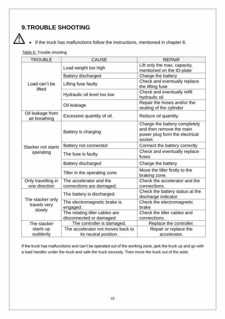
9. TROUBLE SHOOTING
• If the truck has malfunctions follow the instructions, mentioned in chapter 6.
TROUBLE CAUSE REPAIR
Load can’t be lifted
Load weight too high Lift only the max. capacity, mentioned on the ID-plate
Battery discharged Charge the battery
Lifting fuse faulty Check and eventually replace the lifting fuse
Hydraulic oil level too low Check and eventually refill hydraulic oil
Oil leakage Repair the hoses and/or the sealing of the cylinder
Oil leakage from air breathing
Excessive quantity of oil. Reduce oil quantity.
Stacker not starts operating
Battery is charging
Charge the battery completely and then remove the main power plug form the electrical socket.
Battery not connected Connect the battery correctly
The fuse is faulty Check and eventually replace fuses
Battery discharged Charge the battery
Tiller in the operating zone Move the tiller firstly to the braking zone.
Only travelling in one direction
The accelerator and the connections are damaged.
Check the accelerator and the connections.
The stacker only travels very
slowly
The battery is discharged. Check the battery status at the discharge indicator
The electromagnetic brake is engaged.
Check the electromagnetic brake
The relating tiller cables are disconnected or damaged
Check the tiller cables and connections.
The stacker starts up suddenly
The controller is damaged. Replace the controller.
The accelerator not moves back to its neutral position.
Repair or replace the accelerator.
If the truck has malfunctions and can’t be operated out of the working zone, jack the truck up and go with
a load handler under the truck and safe the truck securely. Then move the truck out of the aisle.
Table 6: Trouble shooting

23
10. WIRING/ CIRCUIT DIAGRAM
a. Electrical circuit diagram
Fig. 18: Electrical diagram

24
Code Item Code Item
GB Battery FU01 80A fuse
Et Controller HA Horn
Mp Pump motor FU02 130A fuse
KMp Pump contactor S1 S2 S3 S4 Tiller micro switch
SM Emergency button SY Key switch
YV Electromagnetic valve U 48V charger
SU Micro switch XW Charging cable
BE CAN accelerator FU2 0.5A fuse
SA 48V proximity switch (NO) P 48V BDI
Mt Traction motor K Horn relay
YB Electromagnetic brake SH1 48V proximity switch (NC)
FU1 10A fuse C Capacitor
SE Proximity switch
b. Hydraulic circuit
Fig. 18: Hydraulic circuit
Table 7: Description of electrical diagram

25
11. DECLARATION OF CONFORMITY (valid, if sold within the EU)
[GB] CE Declaration of Conformity The signatory hereby declares that the specified machine conforms to the EU Directive 2006/42/EC (Machine Directive) and 2014/30/EU (Electro-Magnetic Compatibility, EMC) including their amendments as translated into national legislation of the member countries. The signatory is individually authorized to compile the technical documents.
[D] EG-KONFORMITÄTSERKLÄRUNG Der Unterzeichner bescheinigt hiermit, dass die im Einzelnen bezeichnete Maschine den Europäischen Richtlinien 2006/42/EG (Maschinenrichtlinie) und 2014/30/EU (Elektromagnetische Verträglichkeit - EMV) einschließlich deren Änderungen sowie dem entsprechenden Rechtserlaß zur Umsetzung der Richtlinien in nationales Recht entspricht. Der Unterzeichner ist bevollmächtigt, die technischen Unterlagen zusammenzustellen.
[E] DECLARACIóN DE CONFORMIDAD CE El signatario certifico por medio de la presente que la máquina especificada cumple con las Normas Europeas 2006/42/CE (Normativa para maquinarias) y 2014/30/EU (Compatibilidad electromagnética), incluyendo sus respectivas odificaciones, así como con el decreto-ley para la adaptación de las normas al derecho nacional. El signatario dispone de una autorización individual que le permitecompilar la documentacióntécnica.
[F] DECLARATION DE CONFORMITE CE Par la présente déclaration, les soussignés certifient que le machines spécifié ci-dessus est conforme à la loi et aux directives européennes 2006/42/CE (directive sur les machines) et 2014/30/EU (compatibilité électromagnétique - CEM), y compris aux modifications qui y sont apportées et à l’arrêté autorisant sa transposition en droit national. Chaquesignataireesthabilité à établirindividuellement la documentation technique.
[NL] EG-CONFORMITEITSVERKLARING Ondergetekenden verklaren hierbij dat - volgens de nationale wetgeving van de Lidstaten - de hierboven vermelde opgegeven machina beantwoordt aan de bepalingen qua veiligheid bij machines (EG richtlijn 2006/42/EC) en electro-magnetische compatibilteit (EG richtlijn 2014/30/EU). Ondergetekenden zijn ieder individueel gemachtigd het technisch dossier samen te stellen.
[P] DECLARAÇÃO DE CONFORMIDADE CE Pela presente, os signatários certificam que o máquina especificado está conforme às Directivas Europeias 2006/42/CE („Máquinas“) e 2014/30/EU („Inocuidade Electromagnética - IEM“), incluindo as alterações das mesmas e o respectivo decreto-lei para a transposição em lei nacional. Cada um dos signatáriosestáautorizado a proceder à elaboração da documentaçãotécnica.
[I] DICHIARAZIONE DI CONFORMITÀ CE I sottoscrittidichiaranocheilveicolo per trasportiinterniamacchinaspecificatosoddisfa le DirettiveEuropee 2006/42/EC (DirettivaMacchine) e 2014/30/EU (Compatibilitàelettromagnetica - EMV) comprese le relative modifiche, come pure ilrispettivodecretolegislativo per la conversionedelledirettive in dirittonazionale. I sottoscrittisonosingolarmenteautorizzatiallacreazionedelladocumentazionetecnica.
[BG] EВРОПЕЙСКА ОБЩНОСТ - ДЕКЛАРАЦИЯ ЗА СЪОТВЕТСТВИЕ
Подписаните удостоверяват с настоящето, че подробноописанотомашина средствоотговаря на европейския норматив 2006/42/EG (норматив за машини) и на2014/30/EU (електро-магнетична съвместимост), включително с техните промени, както и на съответния указ за прилагане на нормативите в националното право. Подписаните при това са упълномощении поотделно да съставят техническата документация.
[CZ] EG - PROHLÁŠENÍ OSHODĚ Nížepodepsaný tímtopotvrzuje, žepodrobný popisuvedené strojeodpovídáEvropskýmsměrnicím 2006/42/EC (směrniceprostroje) a 2014/30/EU (elektromagnetická interference - EMV) včetně jejichpozdějších úprav, jakož ipříslušnýmprávnímvýnosůmprouplatnění příslušné směrnicevrámcinárodníhopráva. Každý zpodepsanýchjsoujednotlivě zplnomocněnikvytvoření technickýchpodkladů.
[DK] EF-OVERENSSTEMMELSESERKLÆRING Undertegnede attesterer hermed, at det specificerede maskine stemmer overens med de Europæiske Direktiver 2006/42/EU (maskindirektiv) og 2014/30/EU (elektromagnetisk kompatibilitet - EMC) samt med den modsvarende lovvedtagelse til implementering af direktiver i den nationale lovgivning. De undertegnede er hver for sig beføjet til at sammenstille de tekniske dokumenter.
[EST] EL vastavusavaldus Allakirjutanud tõendavad käesolevaga, et üksikasjaliseltkirjeldatudtäpsustatud masin vastab Euroopa direktiividele 2006/42/EÜ (Direktiiv masinate kohta) ja 2014/30/EU (Elektromagnetiline sobivus - EMS) kaasa arvatud nende muudatused ja nendele vastavatele õigusmäärustele direktiivide muutmiseks siseriiklikuks õiguseks. Iga allakirjutanu üksikult on volitatud koostama tehnilist dokumentatsiooni.
[FIN] EU-YHDENMUKAISUUSSELOSTUS Allekirjoittaneet todistavat täten, että kukin erikseen mainittu omalla voimanlähteellä varustettutehdaskone vastaa EU-direktiivien 2006/42/EC (koneenrakennusdirektiivi) ja 2014/30/EU (sähkömagneettinen yhteensopivuus – EMC) määräyksiä sekä niiden muutoksia ja niiden kansalliseen lainsäädäntöön soveltamista koskevaa oikeussääntöä. Jokaisella allekirjoittaneista on oikeus itsenäisesti laatia asiaankuuluvia teknisiä asiakirjoja.
[GR] ΔΗΛΩΣΗΣΥΜΜΟΡΦΩΣΗΣΕΟΚ ΟιυπογράφοντεςβεβαιώνουνδιάτηςπαρούσηςότιτοσυγκεκριμένομηχάνημασυμμορφώνεταιπροςτηνΚοινοτικήΟδηγία 2006/42/ΕΚ («Μηχανήματα») και 2014/30/EU (ΗλεκτρομαγνητικήςΣυμβατότητας, ΗΜΣ), καθώςκαιοιτροποποιήσειςτους, όπωςμεταφράστηκεστηνεθνικήνομοθεσίατωνχωρώνμελών. Οιυπογράφοντεςείναισεκάθεπερίπτωσηεξουσιοδοτημένοιατομικάνακαταρτίσουντατεχνικάέγγραφα.
[H] EU KONFORMITÁSI NYILATKOZAT Alulírottak ezennel igazolják, hogy a részletesen leírt a megadott gép megfelel a 2006/42/EC (Gép-Irányelv) és a 2014/30/EU (Elektromágneses összeférhetőség - EMV) Európai Irányelveknek, beleértve azok módosításait, valamint az irányelvek nemzeti jogba történő átültetésére irányuló megfelelő jogi rendelkezést. Továbbá az alulírottak mindegyike rendelkezik meghatalmazással arra nézve, hogy összeállíthatja a műszaki dokumentációt.
[LT] ES atitikimơ deklaracija
Žemiau pasirašę asmenys patvirtina,kad atskirai aprašytasnurodyta mašina atitinka Europos Sąjungos direktyvas 2006/42/EB (Mašinų direktyva) ir 2014/30/EU (Elektromagnetinis suderinamumas – EMS) įskaitant jų pakeitimus, o taip pat ir atitinkamą teisės aktą dėl direktyvų įgyvendinimo nacionalinėje teisėje. Kiekvienas iš pasirašiusių asmenų turi teisę ruošti techninę dokumentaciją.
[LV] ES atbilstības deklarācija Ar zemāk redzamajiem parakstiem tiek apliecināts, kanorādīts mašīna atbilstEiropas Savienības normatīvām 2006/42/EG (Mašīnu normatīvas) un 2014/30/EU (Elektromagnētiskā atbilstība – EMV), ieskaitot to izmaiņas, kā arī atbilstošos tiesiskos rīkojumus normatīvu pielāgošanai
CE-DD-002

nacionālajai likumdošanai. Parakstu īpašnieki ir atsevišķi pilnvaroti sastādīt tehniskās dokumentācijas.
[N] EU-KONFORMITETSERKLÆRING Undertegnede bekrefter hermed at de enkelte betegnede maskin med kraftdrift tilsvarer de europeiske retningslinjene 2006/42/EC (maskinretningslinje) og 2014/30/EU (elektromagnetisk fordraglighet - EMV) inklusiv disses endringer og den tilsvarende rettsforordning til omsetning av nasjonal rett. Hver undertegnede er fullmektig til å sette sammen de tekniske dokumentene.
[PL] DEKLARACJA ZGODNOŚCI WE Niżej podpisani deklarują, że poniżej opisana maszyna spełnia wymagania określone w dyrektywach Europejskich 2006/42/EC (Dyrektywa Maszynowa) i 2014/30/EU (Kompatybilności elektromagnetycznej - EMC) wraz z ich późniejszymi zmianami oraz odpowiednimi rozporządzeniami mającymi na celu przeniesienie tych dyrektyw do prawa krajów członkowskich. Sygnatariusz jest indywidualnieupoważniony do zestawianiadokumentacjitechnicznej.
[RO] DECLARAŢIE DE CONFORMITATE CE Subsemnaţiiadeverescprinprezentacăvehiculul despecificatmaşinădescris individual corespundedirectiveloreuropene 2006/42/CE (Directivaprivindmaşinile) şi 2014/30/EU (Compatibilitateaelectromagnetică - CEM) inclusivmodificărilorlor precum şiactuluilegislativcorespunzătorprentrutranspunereadirectivelorîndreptnaţional. Subsemnaţii sunt fiecareînparteîmputerniciţisăîntocmeascădocumentaţiatehnică.
[RUS] Декларация соответствия стандартам ЕС
Настоящим лица, подписавшие документ, удостоверяют, что машина с указанной спецификацией соответствует европейским стандартам 2006/42/EG (Транспортная директива) и 2014/30/EU (Электромагнитная совместимость - ЕМС), включая изменения в них, а также соответствующим национальным стандартам и нормам. Каждое по отдельности лицо, подписавшее документ, имеет полномочия для составления технической документации.
[S] EG-KONFORMITETSFÖRKLARING Undertecknarna intygar härmed att det i detalj betecknade maskin uppfyller de Europeiska direktiven 2006/42/EG (Maskindirektiv) och 2014/30/EU (Elektromagnetisk tålighet - EMV), inklusive ändringarna i detta och den motsvarande rättsförordningen för att omsätta direktiven i nationell rätt. Undertecknarna har var för sig fullmakt att sammanställa den tekniska dokumentationen.
[SK] vyhlásenie o zhode Dolu podpísaní týmto potvrdzujeme, že podrobný popis uvedené stroje Zodpovedá Európskym smerniciam 2006/42/EC (ernica pre stroje ) a 2014/30/EU ( elektromagnetická tolerancia – EMV ) vrátane jeho neskorších úprav, rovnako zodpovedá aj príslušným právnym nariadeniam na uplatnenie smerníc v rámci národného práva. Každý z podpísaných je jednotlivo splnomocnený na vytvorenie technických podkladov.
[SLO] EU IZJAVA O SKLADNOSTI Podpisani s tem potrjujemo, da posamično označeno določeno stroj vozilo odgovarja Evropski direktivi 2006/42/EC (Direktiva o strojih) in 2014/30/EU (Elektromagnetna skladnost - EMV) vključno z njihovimi spremembami ter ustrezno pravno uredbo o prevzemu smernic v nacionalno pravo. Podpisniki so vsakokrat posamezno pooblaščeni za izdajanje tehnične dokumentacije.
[TR] AB Uygunluk Açıklaması İmza sahibi şahıslar, ayrıntıları belirtilen makine aracının, 2006/42/EC (Makine Yönergesi) ve 2014/30/EU (Elektromanyetik Uyumluluk – EMC) no'lu Avrupa Yönergelerine ve bunların değişiklik sonucu oluşan metinlerine ve yönergelerin milli hukuk hükümlerine dönüştürülmesine dair ilgili hukuk kararnamesine uygun olduğunu tasdik ederler. İmza sahibi şahıslar teknik dosyaları bir araya getirmek için münferiden vekil tayin edildi.
(1) Type/ Typ/ Tipo/ Modello/ Tyyppi/ Tipo / ΤYΠΟΣ/ Típus/ Tip/ Тип/ Tips/ Tipas/ Tüüp: (2) Serial No./ Serien-Nr./ N°. de série/ Serienummer/ Nº de serie/ Numero di serie/ Serienr./ Sarjanro/ αυξάνωναριθμός/ Seriové číslo/ Szériaszám/
Nr.Seryjny/ Serijska številka/ Výrobné číslo/ Серийныйномер/ Seri No./ Seerianr./ Sērijas Nr./ Serijos numeris: (3) Year of constr./ Baujahr/ Année de constr./ Bouwjaar/ Año de constr./ Anno di costruzione/ Produktionsår/ Byggeår/ Tillverkningsår/ Valmistusvuosi /
Ano de fabrico / έτοςκατασκευής/ Rokvýroby/ Gyártásiév/ Rokprodukcji / Letnik / Годизготовления / Üretimyılı / Väljalaskeaasta / Izgatavošanas gads / Gamybosmetai
(4) Manufacturer or his authorized representative in Community/ Herstelleroder in der Gemeinschaft ansässigerVertreter/ Fabricant ou son mandataireétabli dans la Communauté/ Fabrikant of zijn in de Gemeenschapgevestigdegemachtigde/ Fabricante o representanteestablecidoen la Comunidad/ ConstrutorouRepresentanteestabelecidonaComunidade/ CostruttoreoppureilsuorappresentantenellaComunità/ Fabrikant ellerdennesiFællesskabetetableredebefuldmægtigede/ Produsenteller agent innenfelleskapet/ Tillverkareeller representant inom EU/ Valmistaja tai yhteisömaassaolevaedustaja / V˘robcenebojehozastoupení/ Gyártó / producent albojegoprzedstawiciel w EG (WspólnotaEuropejska)/ Καηαζθεπαζηήο ή όκηινοηνπηθώλ αληηπξνζώπσλ/ Üreticiya da BölgedekiYetkiliTemsilci/ Proizvajalecalipooblaščenizastopnik s sedežem v EU/ Výrobcaalebozástupca so stálymbydliskom v EÚ / Изготовительилиегопредставитель, зарегистрированный в странеСодружества/ Tootjavõiorganisatsioonispaiknevesindaja/ Ražotājsvaivietējaisuzņēmumapārstāvis / Gamintojasarbašalyjereziduojantisatstovas:
(5) Date/ Datum/ Data/ Fecha/ datum/ Dato/ päiväys/ Kuupäev/ Datums/дата/ Dátum/ dátum/ tarih/ ημερομηνία (6) Authorised signatory/ ImAuftrag/ pour ordre/ Incaricato/ Por orden de/ por procuração/ op last van/ påvegneaf/ påuppdrag/ Etteroppdrag/ psta./
Ülesandel / pavedus / v.i. / Попоручению / megbízásából /длъжностнолице / z pověření / z poverenia / po nalogu / napolecenie / din sarcina / adına / θαη' εληνιή
(1) Type: XX XX–Self propelled industrial truck
(2) Serial No: XXXXXXXX
(3) Year of constr.: YYYY
(4) Manufacturer or his authorized representative in Community:
Company name/ Street / Postal code Town/ Country
(5) Date: YYYY.MM.DD
(6) Authorized signatory: Mr. Sample