Embed Size (px)
Citation preview
Proceedings of the ASME 2012 International Design Engineering Technical Conferences &Computers and Information in Engineering Conference
IDETC/CIE 2012August 12-15, 2012, Chicago, Illinois, USA
DETC2012-71266
INSTRUCTION GENERATION FOR ASSEMBLY OPERATIONS PERFORMED BYHUMANS
Krishnanand KaipaCarlos MoratoBoxuan Zhao
Satyandra K. Gupta∗
Department of Mechanical Engineering &Institute for Systems Research
University of MarylandCollege Park, Maryland
ABSTRACTThis paper presents the design of an instruction generation system that can be used to automatically generate instructions
for complex assembly operations performed by humans on factory shop floors. Multimodal information−text, graphical anno-tations, and 3D animations− is used to create easy-to-follow instructions. This thereby reduces learning time and eliminatesthe possibility of assembly errors. An automated motion planning subsystem computes a collision-free path for each part fromits initial posture in a crowded scene onto its final posture in the current subassembly. Visualization of this computed motionresults in generation of 3D animations. The system also consists of an automated part identification module that enables thehuman to identify, and pick, the correct part from a set of similar looking parts. The system’s ability to automatically translateassembly plans into instructions enables a significant reduction in the time taken to generate instructions and update them inresponse to design changes.
1 INTRODUCTIONProduct manufacturing involves complex assembly operations that must be performed by humans and/or robots. Within this setting,
it is imperative to define the operational roles of the human and the robot appropriately. Whereas robots are superior to humans athandling repetitive tasks like welding and bolting, humans are better at performing tasks like picking, carrying, and placing a wide rangeof parts without using special fixtures; humans also have a natural ability to handle several assembly equipment easily. However, humansare prone to committing assembly related mistakes. Human workers usually follow a list of instructions to carry out assembly operationson the shop floor. However, poor instructions lead to assembly errors and increased learning time. Therefore, there is a need for effective,and yet, easy-to-follow assembly instructions for humans. Manual generation of such high quality instructions is a time consuming taskwhen utilizing shared setups and tools. This thereby motivates the need for automated generation of instructions for human workers.
In this paper, we present the design of an instruction generation system that can be used to automatically generate instructions
∗Address all correspondence to this author.
1 Copyright c© 2012 by ASME
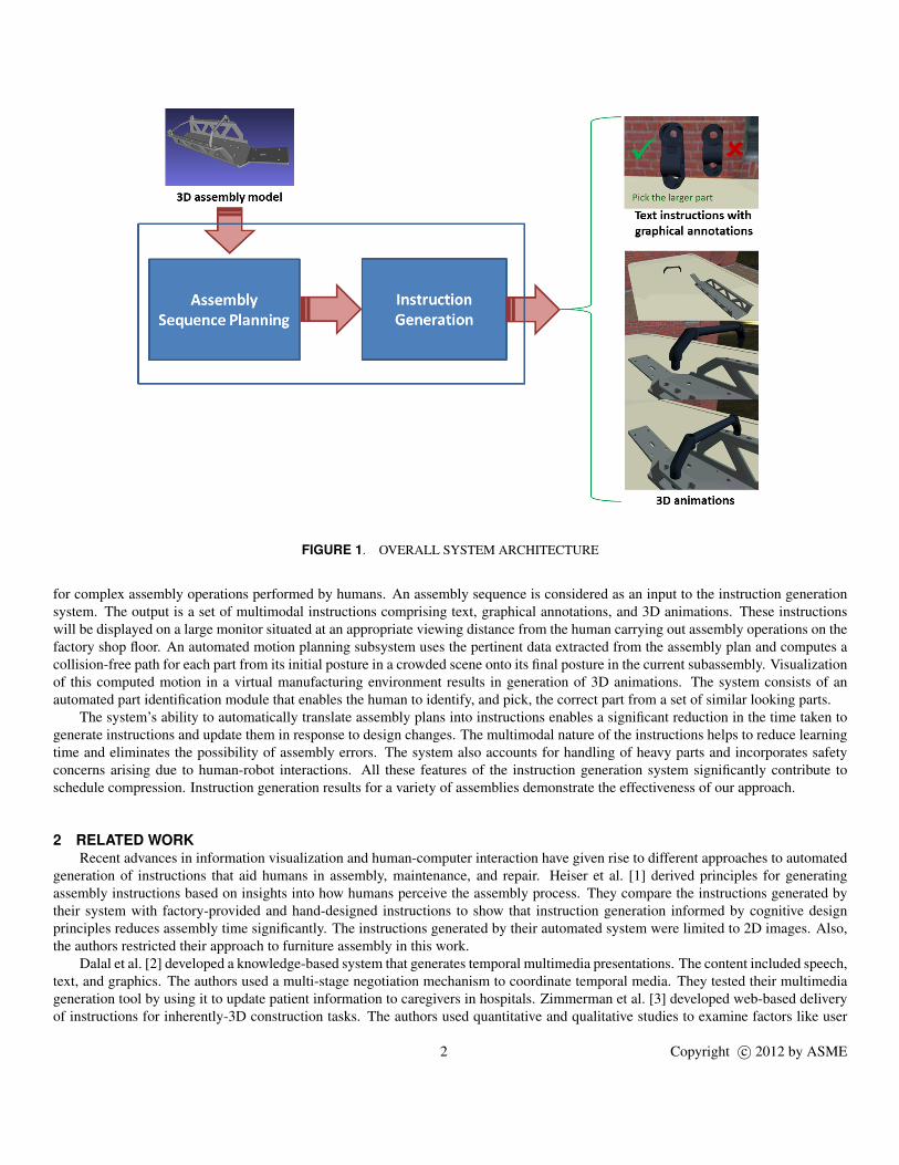
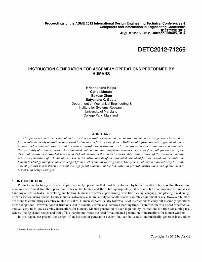
FIGURE 1. OVERALL SYSTEM ARCHITECTURE
for complex assembly operations performed by humans. An assembly sequence is considered as an input to the instruction generationsystem. The output is a set of multimodal instructions comprising text, graphical annotations, and 3D animations. These instructionswill be displayed on a large monitor situated at an appropriate viewing distance from the human carrying out assembly operations on thefactory shop floor. An automated motion planning subsystem uses the pertinent data extracted from the assembly plan and computes acollision-free path for each part from its initial posture in a crowded scene onto its final posture in the current subassembly. Visualizationof this computed motion in a virtual manufacturing environment results in generation of 3D animations. The system consists of anautomated part identification module that enables the human to identify, and pick, the correct part from a set of similar looking parts.
The system’s ability to automatically translate assembly plans into instructions enables a significant reduction in the time taken togenerate instructions and update them in response to design changes. The multimodal nature of the instructions helps to reduce learningtime and eliminates the possibility of assembly errors. The system also accounts for handling of heavy parts and incorporates safetyconcerns arising due to human-robot interactions. All these features of the instruction generation system significantly contribute toschedule compression. Instruction generation results for a variety of assemblies demonstrate the effectiveness of our approach.
2 RELATED WORKRecent advances in information visualization and human-computer interaction have given rise to different approaches to automated
generation of instructions that aid humans in assembly, maintenance, and repair. Heiser et al. [1] derived principles for generatingassembly instructions based on insights into how humans perceive the assembly process. They compare the instructions generated bytheir system with factory-provided and hand-designed instructions to show that instruction generation informed by cognitive designprinciples reduces assembly time significantly. The instructions generated by their automated system were limited to 2D images. Also,the authors restricted their approach to furniture assembly in this work.
Dalal et al. [2] developed a knowledge-based system that generates temporal multimedia presentations. The content included speech,text, and graphics. The authors used a multi-stage negotiation mechanism to coordinate temporal media. They tested their multimediageneration tool by using it to update patient information to caregivers in hospitals. Zimmerman et al. [3] developed web-based deliveryof instructions for inherently-3D construction tasks. The authors used quantitative and qualitative studies to examine factors like user
2 Copyright c© 2012 by ASME
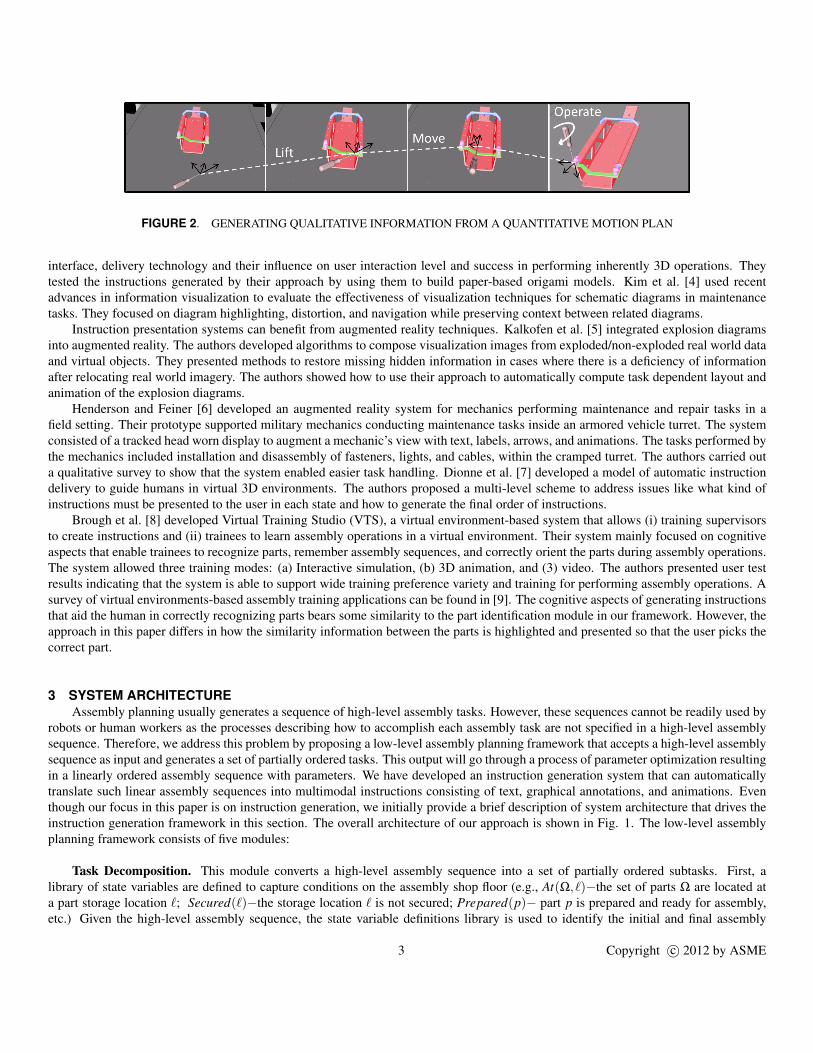
FIGURE 2. GENERATING QUALITATIVE INFORMATION FROM A QUANTITATIVE MOTION PLAN
interface, delivery technology and their influence on user interaction level and success in performing inherently 3D operations. Theytested the instructions generated by their approach by using them to build paper-based origami models. Kim et al. [4] used recentadvances in information visualization to evaluate the effectiveness of visualization techniques for schematic diagrams in maintenancetasks. They focused on diagram highlighting, distortion, and navigation while preserving context between related diagrams.
Instruction presentation systems can benefit from augmented reality techniques. Kalkofen et al. [5] integrated explosion diagramsinto augmented reality. The authors developed algorithms to compose visualization images from exploded/non-exploded real world dataand virtual objects. They presented methods to restore missing hidden information in cases where there is a deficiency of informationafter relocating real world imagery. The authors showed how to use their approach to automatically compute task dependent layout andanimation of the explosion diagrams.
Henderson and Feiner [6] developed an augmented reality system for mechanics performing maintenance and repair tasks in afield setting. Their prototype supported military mechanics conducting maintenance tasks inside an armored vehicle turret. The systemconsisted of a tracked head worn display to augment a mechanic’s view with text, labels, arrows, and animations. The tasks performed bythe mechanics included installation and disassembly of fasteners, lights, and cables, within the cramped turret. The authors carried outa qualitative survey to show that the system enabled easier task handling. Dionne et al. [7] developed a model of automatic instructiondelivery to guide humans in virtual 3D environments. The authors proposed a multi-level scheme to address issues like what kind ofinstructions must be presented to the user in each state and how to generate the final order of instructions.
Brough et al. [8] developed Virtual Training Studio (VTS), a virtual environment-based system that allows (i) training supervisorsto create instructions and (ii) trainees to learn assembly operations in a virtual environment. Their system mainly focused on cognitiveaspects that enable trainees to recognize parts, remember assembly sequences, and correctly orient the parts during assembly operations.The system allowed three training modes: (a) Interactive simulation, (b) 3D animation, and (3) video. The authors presented user testresults indicating that the system is able to support wide training preference variety and training for performing assembly operations. Asurvey of virtual environments-based assembly training applications can be found in [9]. The cognitive aspects of generating instructionsthat aid the human in correctly recognizing parts bears some similarity to the part identification module in our framework. However, theapproach in this paper differs in how the similarity information between the parts is highlighted and presented so that the user picks thecorrect part.
3 SYSTEM ARCHITECTUREAssembly planning usually generates a sequence of high-level assembly tasks. However, these sequences cannot be readily used by
robots or human workers as the processes describing how to accomplish each assembly task are not specified in a high-level assemblysequence. Therefore, we address this problem by proposing a low-level assembly planning framework that accepts a high-level assemblysequence as input and generates a set of partially ordered tasks. This output will go through a process of parameter optimization resultingin a linearly ordered assembly sequence with parameters. We have developed an instruction generation system that can automaticallytranslate such linear assembly sequences into multimodal instructions consisting of text, graphical annotations, and animations. Eventhough our focus in this paper is on instruction generation, we initially provide a brief description of system architecture that drives theinstruction generation framework in this section. The overall architecture of our approach is shown in Fig. 1. The low-level assemblyplanning framework consists of five modules:
Task Decomposition. This module converts a high-level assembly sequence into a set of partially ordered subtasks. First, alibrary of state variables are defined to capture conditions on the assembly shop floor (e.g., At(Ω, `)−the set of parts Ω are located ata part storage location `; Secured(`)−the storage location ` is not secured; Prepared(p)− part p is prepared and ready for assembly,etc.) Given the high-level assembly sequence, the state variable definitions library is used to identify the initial and final assembly
3 Copyright c© 2012 by ASME
FIGURE 3. (a) ATTACHMENT OF A VENT PANEL TO AN ENGINE HOOD. (b) BOTTOM VIEW OF THE PANEL SHOWING A SEMICIR-CULAR NOTCH ON ONE OF ITS EDGES.
TABLE 1. A TEMPLATE OF BASIC SUBTASKS.
Basic subtasks Description
Access(o, `) Access object o at location `
Identi f y(o,Ω) Identify object o from object set Ω
Retrieve(o) Retrieve object o that was just accessed and identified
Transport(o, `1, `2) Transport object o from location `1 to location `2
Prepare(o) Prepare object o for the assembly operation
Clamp(o, `) Clamp object o to ground at location `
Check(o) Check if the object o is ready for assembly
Position(o,℘,ψ) Position object o at position ℘ and orientation ψ
Insert(o1,o2) Insert object o1 into object o2
Attach(o1,o2) Attach object o1 to object o2
Inspect(o) Inspect object o for correctness of assembly
Secure(`) Secure location `
states. Second, a library of basic subtasks templates that encompass all the assembly operations carried out on the factory shop floor isgenerated. One example of such a template is shown in Table 1. Now, the initial and final assembly states, identified in the first step, arematched with the subtasks template library to enumerate a list of subtasks. This will be followed by binding of variables and eliminationof null tasks, giving rise to a partial order on the subtasks that can accomplish the tasks in the given assembly sequence
Method Selection. In this context, we define a method as a prescription of how a subtask must be implemented. For example, ifTransport(p, `ps, `w) is a subtask, then the method to transport the part p could be manual, by using a trolley, or by using a crane andslings. The weight of the part is used as a parameter to trigger which transport method will be selected. A methods-decision tree iscreated and used to compute methods for all the partially ordered subtasks.
Tool Selection. The output of the previous module is a set of methods and tools to implement these methods. In the tool selectionmodule, motion planning based on Rapidly-exploring Random Trees (RRT) for coupled 6 DOF tool and simplified human hand models
4 Copyright c© 2012 by ASME
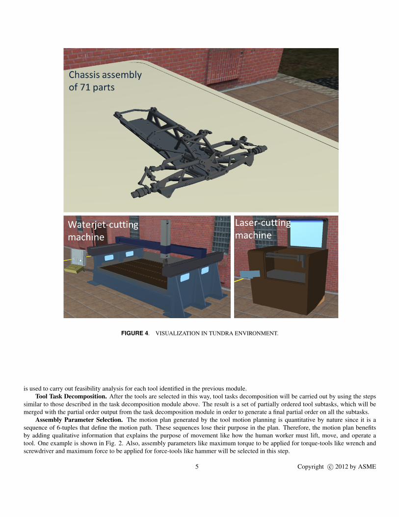
FIGURE 4. VISUALIZATION IN TUNDRA ENVIRONMENT.
is used to carry out feasibility analysis for each tool identified in the previous module.Tool Task Decomposition. After the tools are selected in this way, tool tasks decomposition will be carried out by using the steps
similar to those described in the task decomposition module above. The result is a set of partially ordered tool subtasks, which will bemerged with the partial order output from the task decomposition module in order to generate a final partial order on all the subtasks.
Assembly Parameter Selection. The motion plan generated by the tool motion planning is quantitative by nature since it is asequence of 6-tuples that define the motion path. These sequences lose their purpose in the plan. Therefore, the motion plan benefitsby adding qualitative information that explains the purpose of movement like how the human worker must lift, move, and operate atool. One example is shown in Fig. 2. Also, assembly parameters like maximum torque to be applied for torque-tools like wrench andscrewdriver and maximum force to be applied for force-tools like hammer will be selected in this step.
5 Copyright c© 2012 by ASME

4 INSTRUCTION GENERATION FRAMEWORKThe input to the instruction generation system is a linearly ordered assembly sequence represented in the extensible markup language
(e.g., plan.xml). The contents of each step in the plan.xml file will be used to generate multimodal instructions in the form of text, images,and animations. Next, the various components that constitute the design of the instruction generation system−the language and grammarfor text instructions, the process of how the animations will be generated automatically, automated part identification, and instructionpresentation−are described briefly.
4.1 Text InstructionsThe language for text instructions will consist of simple verbs such as Identify, Attach, Position, Rotate, Push, Pull, Lift, Lower,
Check, Pick, Place, Use, etc. Examples of grammatical constructs for the text instructions include:
1. Lift PART? by HEIGHT?2. Use HOW MANY? PART? of type TYPE?, capacity CAPACITY? , length LENGTH?3. Position PART? on LOCATION?4. Position PART? so that FEATURE-A? aligns with FEATURE-B?5. Attach PART? at LOCATION?6. Attach PART-A? to PART-B? so that FEATURE-A? mates with FEATURE-B?
To illustrate text instructions, consider the process of attaching an asymmetric vent panel to the engine hood as shown in Fig. 3(a).To the naked eye, the panel appears symmetric, leading to confusion in correctly orienting it before placing on the hood. In Fig. 3(b),notice a semicircular notch on one bottom-side panel edge. This feature can be used during instruction presentation to guide the humanworker in mating the correct panel face with the engine hood before proceeding with attachment.
This framework then generates the following text instructions:
1. Press YELLOW BUTTON to reset ROBOT22. Apply FLUX on edges of VENT-PANEL-BOTTOM (special instruction)3. Pick up VENT-PANEL MANUALLY4. Position VENT-PANEL so that VENT-PANEL-NOTECHED-EDGE aligns with HOOD-FRONT-EDGE (View Animation)5. Attach VENT-PANEL to HOOD so that VENT-PANEL-BOTTOM mates with HOOD-TOP6. Press ORANGE BUTTON to start ROBOT27. Press BLACK BUTTON to switch off ROBOT2 when ROBOT2 halts
4.2 Automated Generation of AnimationsThe information extracted from plan.xml includes details about the initial scene, labels of the parts and/or subassemblies involved
in the assembly operation, and their initial/final postures. This data from each step of the plan is used to invoke a simulation ofthe assembly operation in a virtual visualization environment, which was developed based on Tundra software. A snapshot of thevisualization in Tundra is shown in Fig. 4. An automated motion planning module interacts with the visualization environment andcomputes a collision-free motion of a part from its initial posture (e.g., the hood lying in a shelf) to its final posture (e.g., placing of thehood onto the engine compartment of the space frame). Visualization of this computed motion in the visualization environment resultsin animations that will be appropriately labeled and saved as video clips in a local computer directory. We use dynamic multi-randomtrees (DMRT), a variation of rapidly-exploring random trees, for the purpose of motion planning. In a different paper [10], we report thedetails of how we use DMRT based motion planning to automatically generate feasible assembly sequences directly from 3D models ofcomplex assemblies.
4.3 Part Identification InstructionsUsually, when a set of parts is presented to a human worker, he/she can easily distinguish among most of them. However, a few
may look similar to each other, leading to confusion about which to pick. We have developed a part identification tool to determineautomatically the presence of such similar looking parts and present them in a way that allows a worker to identify and pick the correctpart. For this purpose, a similarity metric between two parts is constructed based on the following attributes [11, 12]:
1. Part volume and surface area2. Basic shape statistics such as the types of surfaces and their corresponding areas
6 Copyright c© 2012 by ASME
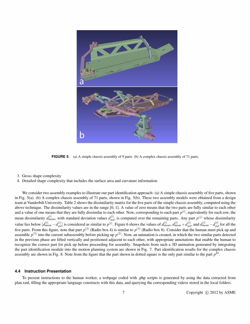
FIGURE 5. (a) A simple chassis assembly of 9 parts. (b) A complex chassis assembly of 71 parts.
3. Gross shape complexity4. Detailed shape complexity that includes the surface area and curvature information
We consider two assembly examples to illustrate our part identification approach: (a) A simple chassis assembly of five parts, shownin Fig. 5(a). (b) A complex chassis assembly of 71 parts, shown in Fig. 5(b). These two assembly models were obtained from a designteam at Vanderbilt University. Table 2 shows the dissimilarity matrix for the five parts of the simple chassis assembly, computed using theabove technique. The dissimilarity values are in the range [0, 1]. A value of zero means that the two parts are fully similar to each otherand a value of one means that they are fully dissimilar to each other. Now, corresponding to each part p(i), equivalently for each row, themean dissimilarity d(i)
mean, with standard deviation values d(i)std , is computed over the remaining parts. Any part p( j) whose dissimilarity
value lies below [d(i)mean−d(i)
std ] is considered as similar to p(i). Figure 6 shows the values of d(i)mean, d(i)
mean+d(i)std , and d(i)
mean−d(i)std for all the
five parts. From this figure, note that part p(2) (Radio box 4) is similar to p(3) (Radio box 8). Consider that the human must pick up andassemble p(3) into the current subassembly before picking up p(2). Now, an animation is created, in which the two similar parts detectedin the previous phase are lifted vertically and positioned adjacent to each other, with appropriate annotations that enable the human torecognize the correct part for pick up before proceeding for assembly. Snapshots from such a 3D animation generated by integratingthe part identification module into the motion planning system are shown in Fig. 7. Part identification results for the complex chassisassembly are shown in Fig. 8. Note from the figure that the part shown in dotted square is the only part similar to the part p45.
4.4 Instruction Presentation
To present instructions to the human worker, a webpage coded with .php scripts is generated by using the data extracted fromplan.xml, filling the appropriate language constructs with this data, and querying the corresponding videos stored in the local folders.
7 Copyright c© 2012 by ASME
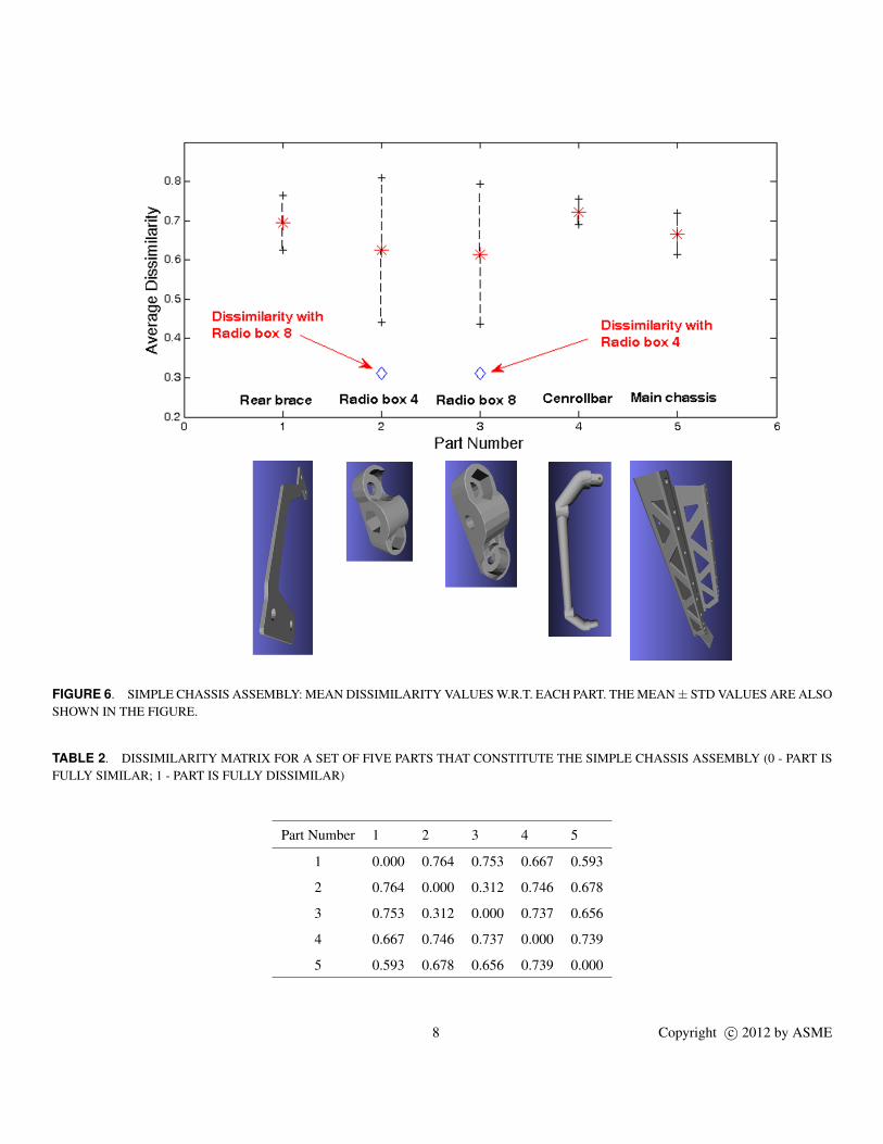
FIGURE 6. SIMPLE CHASSIS ASSEMBLY: MEAN DISSIMILARITY VALUES W.R.T. EACH PART. THE MEAN ± STD VALUES ARE ALSOSHOWN IN THE FIGURE.
TABLE 2. DISSIMILARITY MATRIX FOR A SET OF FIVE PARTS THAT CONSTITUTE THE SIMPLE CHASSIS ASSEMBLY (0 - PART ISFULLY SIMILAR; 1 - PART IS FULLY DISSIMILAR)
Part Number 1 2 3 4 5
1 0.000 0.764 0.753 0.667 0.593
2 0.764 0.000 0.312 0.746 0.678
3 0.753 0.312 0.000 0.737 0.656
4 0.667 0.746 0.737 0.000 0.739
5 0.593 0.678 0.656 0.739 0.000
8 Copyright c© 2012 by ASME
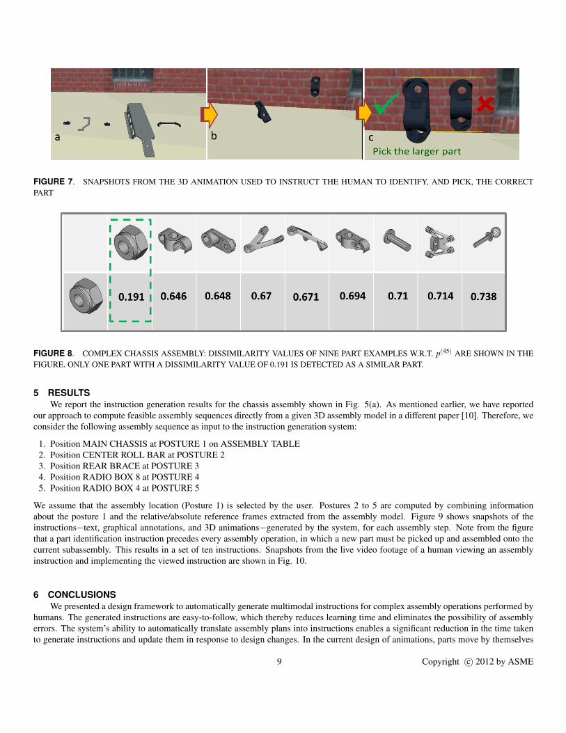
FIGURE 7. SNAPSHOTS FROM THE 3D ANIMATION USED TO INSTRUCT THE HUMAN TO IDENTIFY, AND PICK, THE CORRECTPART
FIGURE 8. COMPLEX CHASSIS ASSEMBLY: DISSIMILARITY VALUES OF NINE PART EXAMPLES W.R.T. p(45) ARE SHOWN IN THEFIGURE. ONLY ONE PART WITH A DISSIMILARITY VALUE OF 0.191 IS DETECTED AS A SIMILAR PART.
5 RESULTSWe report the instruction generation results for the chassis assembly shown in Fig. 5(a). As mentioned earlier, we have reported
our approach to compute feasible assembly sequences directly from a given 3D assembly model in a different paper [10]. Therefore, weconsider the following assembly sequence as input to the instruction generation system:
1. Position MAIN CHASSIS at POSTURE 1 on ASSEMBLY TABLE2. Position CENTER ROLL BAR at POSTURE 23. Position REAR BRACE at POSTURE 34. Position RADIO BOX 8 at POSTURE 45. Position RADIO BOX 4 at POSTURE 5
We assume that the assembly location (Posture 1) is selected by the user. Postures 2 to 5 are computed by combining informationabout the posture 1 and the relative/absolute reference frames extracted from the assembly model. Figure 9 shows snapshots of theinstructions−text, graphical annotations, and 3D animations−generated by the system, for each assembly step. Note from the figurethat a part identification instruction precedes every assembly operation, in which a new part must be picked up and assembled onto thecurrent subassembly. This results in a set of ten instructions. Snapshots from the live video footage of a human viewing an assemblyinstruction and implementing the viewed instruction are shown in Fig. 10.
6 CONCLUSIONSWe presented a design framework to automatically generate multimodal instructions for complex assembly operations performed by
humans. The generated instructions are easy-to-follow, which thereby reduces learning time and eliminates the possibility of assemblyerrors. The system’s ability to automatically translate assembly plans into instructions enables a significant reduction in the time takento generate instructions and update them in response to design changes. In the current design of animations, parts move by themselves
9 Copyright c© 2012 by ASME
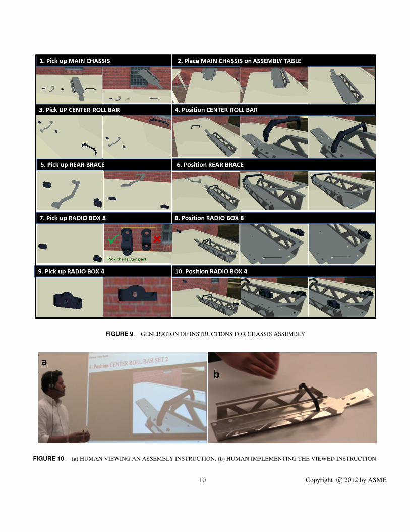
FIGURE 9. GENERATION OF INSTRUCTIONS FOR CHASSIS ASSEMBLY
FIGURE 10. (a) HUMAN VIEWING AN ASSEMBLY INSTRUCTION. (b) HUMAN IMPLEMENTING THE VIEWED INSTRUCTION.
10 Copyright c© 2012 by ASME

from initial to final postures. As the animation generation is grounded in motion planning, this issue can be addressed by incorporatinghuman models, with increasingly complex degrees of freedom, into the framework. This results in more realistic animations that utilizea human model to show how to lift and move the parts/tools during assembly.
ACKNOWLEDGMENTThis work was supported by DARPA AVM iFab Project (Contract # FA8650-11-C-7128). This project was a large collaborative
effort involving Carnegie Mellon University, Lockheed Martin, Pratt and Miller, University of Maryland, and University of Michigan.We acknowledge and thank all members of our team for their valuable input. We especially would like to thank David Bourne fromCarnegie Mellon University for sharing his valuable insights and feedback. We are also thankful to META team at Vanderbilt Universityfor providing assemblies used in this paper.
REFERENCES[1] Heiser, J., Phan, D., Agrawala, M., Tversky, B., and Hanrahan, P., 1995. “Identification and validation of cognitive design principles
for automated generation of assembly instructions”. In Proceedings of the working conference on Advanced visual interfaces,Gallipoli, Italy, pp. 311–319.
[2] Dalal, M., Feiner, S., McKeown, K., Pan, S., Zhou, M., Hollerer, T., Shaw, J., Feng, Y., and Fromer, J., 1996. “Negotiationfor automated generation of temporal multimedia presentations”. In Proceedings of the fourth ACM international conference onMultimedia, Boston, MA, pp. 55–64.
[3] Zimmerman, G., Barnes, J., and Leventhal, L., 2003. “A comparison of the usability and effectiveness of web-based delivery ofinstructions for inherently-3D construction tasks on handheld and desktop computers”. In Proceedings of the eighth internationalconference on 3D Web technology, Saint Malo, France, pp. 49–54.
[4] Kim, S., Woo, I., Maciejewski, R., Ebert, D.S., Ropp, T.D., and Thomas, K., 2010. “Evaluating the effectiveness of visualizationtechniques for schematic diagrams in maintenance tasks”. In Proceedings of the 7th Symposium on Applied Perception in Graphicsand Visualization, Los Angeles, CA, pp. 33–40.
[5] Kalkofen, D., Tatzgern, M., Schmalstieg, D., 2009. “Explosion diagrams in augmented reality”. In Proceedings of IEEE Interna-tional Conference on Virtual Reality, pp. 71–78.
[6] Henderson, S., and Feiner, S., 2011. “Exploring the Benefits of Augmented Reality Documentation for Maintenance and Repair”.IEEE Transactions on Visualization and Computer Graphics, 17(10), pp. 1355–1368.
[7] Dionne, D., de la Puente, S., LeOn, C., and HervAs, R., and GervAs, P., 2010. “A model for human readable instruction generationusing level-based discourse planning and dynamic inference of attributes disambiguation”. In Proceedings of the 12th EuropeanWorkshop on Natural Language Generation, Athens, Greece.
[8] Brough, J.E., Schwartz, M., Gupta, S.K., Anand, D.K., Kavetsky, R., and Pettersen, R., 2007. “Towards development of a virtualenvironment-based training system for mechanical assembly operations”. Virtual Reality, 11(4), pp. 189–206.
[9] Gupta, S.K., Anand, D.K., Brough, J.E., Schwartz, M., and Kavetsky, R., 2008. Training in Virtual Environments: A Safe, Cost-Effective, and Engaging Approach to Training. CALCE EPSC Press, College Park, MD.
[10] Morato, C., Kaipa, K.N., and Gupta, S.K., 2012. “Assembly sequence planning by using dynamic multi-random trees based motionplanning”. In Proceedings of ASME International Design Engineering Technical Conferences, IDETC/CIE, Chicago, Illinois.
[11] Cardone, A., Gupta, S.K., and Karnik, M., 2003. “A survey of shape similarity assessment algorithms for product design andmanufacturing applications”. Journal of Computing and Information Science in Engineering, 3(2), pp. 109–118.
[12] Cardone, A., and Gupta, S.K., 2006. “Shape similarity assessment based on face alignment using attributed applied vectors”. InProceedings of CAD Conference, Phuket Island, Thailand.
11 Copyright c© 2012 by ASME


![This document contains the draft version of the following ...terpconnect.umd.edu/~skgupta/Publication/VR07_Brough_draft.pdfassembly system [9]. Gupta et al. describe a system for prototyping](https://img.pdfslide.us/doc/110x75/5ea82880e26406643b50d073/this-document-contains-the-draft-version-of-the-following-skguptapublicationvr07broughdraftpdf.jpg)