Embed Size (px)
Citation preview
INST
RU
CT
ION
MA
NU
AL
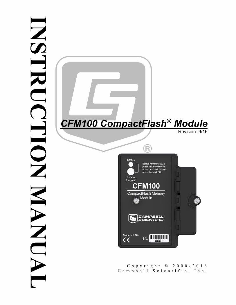
CFM100 CompactFlash® Module
Revision: 9/16
C o p y r i g h t © 2 0 0 0 - 2 0 1 6C a m p b e l l S c i e n t i f i c , I n c .

Guarantee
This equipment is guaranteed against defects in materials and workmanship.
We will repair or replace products which prove to be defective during the
guarantee period as detailed on your invoice, provided they are returned to us
prepaid. The guarantee will not apply to:
Equipment which has been modified or altered in any way without the
written permission of Campbell Scientific
Batteries
Any product which has been subjected to misuse, neglect, acts of God or
damage in transit.
Campbell Scientific will return guaranteed equipment by surface carrier
prepaid. Campbell Scientific will not reimburse the claimant for costs incurred
in removing and/or reinstalling equipment. This guarantee and the Company’s
obligation thereunder is in lieu of all other guarantees, expressed or implied,
including those of suitability and fitness for a particular purpose. Campbell
Scientific is not liable for consequential damage.
Please inform us before returning equipment and obtain a Repair Reference
Number whether the repair is under guarantee or not. Please state the faults as
clearly as possible, and if the product is out of the guarantee period it should
be accompanied by a purchase order. Quotations for repairs can be given on
request. It is the policy of Campbell Scientific to protect the health of its
employees and provide a safe working environment, in support of this policy a
“Declaration of Hazardous Material and Decontamination” form will be
issued for completion.
When returning equipment, the Repair Reference Number must be clearly
marked on the outside of the package. Complete the “Declaration of
Hazardous Material and Decontamination” form and ensure a completed copy
is returned with your goods. Please note your Repair may not be processed if
you do not include a copy of this form and Campbell Scientific Ltd reserves
the right to return goods at the customers’ expense.
Note that goods sent air freight are subject to Customs clearance fees which
Campbell Scientific will charge to customers. In many cases, these charges are
greater than the cost of the repair.
Campbell Scientific Ltd,
80 Hathern Road,
Shepshed, Loughborough, LE12 9GX, UK
Tel: +44 (0) 1509 601141
Fax: +44 (0) 1509 601091
Email: [email protected]
www.campbellsci.co.uk

PLEASE READ FIRST
About this manual
Please note that this manual was originally produced by Campbell Scientific Inc. primarily for the North
American market. Some spellings, weights and measures may reflect this origin.
Some useful conversion factors:
Area: 1 in2 (square inch) = 645 mm
2
Length: 1 in. (inch) = 25.4 mm
1 ft (foot) = 304.8 mm
1 yard = 0.914 m
1 mile = 1.609 km
Mass: 1 oz. (ounce) = 28.35 g
1 lb (pound weight) = 0.454 kg
Pressure: 1 psi (lb/in2) = 68.95 mb
Volume: 1 UK pint = 568.3 ml
1 UK gallon = 4.546 litres
1 US gallon = 3.785 litres
In addition, while most of the information in the manual is correct for all countries, certain information
is specific to the North American market and so may not be applicable to European users.
Differences include the U.S standard external power supply details where some information (for
example the AC transformer input voltage) will not be applicable for British/European use. Please note,
however, that when a power supply adapter is ordered it will be suitable for use in your country.
Reference to some radio transmitters, digital cell phones and aerials may also not be applicable
according to your locality.
Some brackets, shields and enclosure options, including wiring, are not sold as standard items in the
European market; in some cases alternatives are offered. Details of the alternatives will be covered in
separate manuals.
Part numbers prefixed with a “#” symbol are special order parts for use with non-EU variants or for
special installations. Please quote the full part number with the # when ordering.
Recycling information
At the end of this product’s life it should not be put in commercial or domestic refuse but
sent for recycling. Any batteries contained within the product or used during the
products life should be removed from the product and also be sent to an appropriate
recycling facility.
Campbell Scientific Ltd can advise on the recycling of the equipment and in some cases
arrange collection and the correct disposal of it, although charges may apply for some
items or territories.
For further advice or support, please contact Campbell Scientific Ltd, or your local agent.
Campbell Scientific Ltd, 80 Hathern Road, Shepshed, Loughborough, LE12 9GX, UK
Tel: +44 (0) 1509 601141 Fax: +44 (0) 1509 601091
Email: [email protected]
www.campbellsci.co.uk


Precautions DANGER — MANY HAZARDS ARE ASSOCIATED WITH INSTALLING, USING, MAINTAINING, AND WORKING ON OR AROUND TRIPODS, TOWERS, AND ANY ATTACHMENTS TO TRIPODS AND TOWERS SUCH AS SENSORS, CROSSARMS, ENCLOSURES, ANTENNAS, ETC. FAILURE TO PROPERLY AND COMPLETELY ASSEMBLE, INSTALL, OPERATE, USE, AND MAINTAIN TRIPODS, TOWERS, AND ATTACHMENTS, AND FAILURE TO HEED WARNINGS, INCREASES THE RISK OF DEATH, ACCIDENT, SERIOUS INJURY, PROPERTY DAMAGE, AND PRODUCT FAILURE. TAKE ALL REASONABLE PRECAUTIONS TO AVOID THESE HAZARDS. CHECK WITH YOUR ORGANIZATION'S SAFETY COORDINATOR (OR POLICY) FOR PROCEDURES AND REQUIRED PROTECTIVE EQUIPMENT PRIOR TO PERFORMING ANY WORK.
Use tripods, towers, and attachments to tripods and towers only for purposes for which they are designed. Do not exceed design limits. Be familiar and comply with all instructions provided in product manuals. Manuals are available at www.campbellsci.eu or by telephoning +44(0) 1509 828 888 (UK). You are responsible for conformance with governing codes and regulations, including safety regulations, and the integrity and location of structures or land to which towers, tripods, and any attachments are attached. Installation sites should be evaluated and approved by a qualified engineer. If questions or concerns arise regarding installation, use, or maintenance of tripods, towers, attachments, or electrical connections, consult with a licensed and qualified engineer or electrician.
General • Prior to performing site or installation work, obtain required approvals and permits. Comply with all
governing structure-height regulations, such as those of the FAA in the USA. • Use only qualified personnel for installation, use, and maintenance of tripods and towers, and any
attachments to tripods and towers. The use of licensed and qualified contractors is highly recommended. • Read all applicable instructions carefully and understand procedures thoroughly before beginning work. • Wear a hardhat and eye protection, and take other appropriate safety precautions while working on or
around tripods and towers. • Do not climb tripods or towers at any time, and prohibit climbing by other persons. Take reasonable
precautions to secure tripod and tower sites from trespassers. • Use only manufacturer recommended parts, materials, and tools.
Utility and Electrical • You can be killed or sustain serious bodily injury if the tripod, tower, or attachments you are installing,
constructing, using, or maintaining, or a tool, stake, or anchor, come in contact with overhead or underground utility lines.
• Maintain a distance of at least one-and-one-half times structure height, or 20 feet, or the distance required by applicable law, whichever is greater, between overhead utility lines and the structure (tripod, tower, attachments, or tools).
• Prior to performing site or installation work, inform all utility companies and have all underground utilities marked.
• Comply with all electrical codes. Electrical equipment and related grounding devices should be installed by a licensed and qualified electrician.
Elevated Work and Weather • Exercise extreme caution when performing elevated work. • Use appropriate equipment and safety practices. • During installation and maintenance, keep tower and tripod sites clear of un-trained or non-essential
personnel. Take precautions to prevent elevated tools and objects from dropping. • Do not perform any work in inclement weather, including wind, rain, snow, lightning, etc.
Maintenance • Periodically (at least yearly) check for wear and damage, including corrosion, stress cracks, frayed cables,
loose cable clamps, cable tightness, etc. and take necessary corrective actions. • Periodically (at least yearly) check electrical ground connections.
WHILE EVERY ATTEMPT IS MADE TO EMBODY THE HIGHEST DEGREE OF SAFETY IN ALL CAMPBELL SCIENTIFIC PRODUCTS, THE CUSTOMER ASSUMES ALL RISK FROM ANY INJURY RESULTING FROM IMPROPER INSTALLATION, USE, OR MAINTENANCE OF TRIPODS, TOWERS, OR ATTACHMENTS TO TRIPODS AND TOWERS SUCH AS SENSORS, CROSSARMS, ENCLOSURES, ANTENNAS, ETC.


i
Table of Contents PDF viewers: These page numbers refer to the printed version of this document. Use the PDF reader bookmarks tab for links to specific sections.
1. Introduction ................................................................ 1
2. Precautions ................................................................ 1
3. Initial Inspection ......................................................... 2
4. QuickStart ................................................................... 2
4.1 Preparation ........................................................................................... 2 4.2 Programming the Datalogger to Send Data to the CFM100 ................ 2 4.3 Data Retrieval ...................................................................................... 3
5. Overview ..................................................................... 3
5.1 LEDs/Buttons ....................................................................................... 4 5.2 Power ................................................................................................... 5
5.2.1 Primary Power .............................................................................. 5 5.2.2 Backup Power and Data Retention ............................................... 5
6. Specifications ............................................................. 5
6.1 Power ................................................................................................... 5
7. Operation .................................................................... 6
7.1 File Formats ......................................................................................... 6 7.1.1 Data Files ...................................................................................... 6 7.1.2 Program Files ................................................................................ 6 7.1.3 Power-Up Files (Powerup.ini) ...................................................... 6
7.1.3.1 Creating and Editing Powerup.ini ...................................... 7 7.1.3.2 Applications ....................................................................... 8 7.1.3.3 Program Execution ............................................................. 8 7.1.3.4 Example Powerup.ini Files ................................................. 9
7.1.4 Camera Files ................................................................................. 9 7.2 Programming ........................................................................................ 9
7.2.1 The CardOut() Instruction ............................................................. 9 7.2.2 Program Examples ...................................................................... 10
7.2.2.1 Ring Mode ........................................................................ 10 7.2.2.2 Fill-and-Stop Mode .......................................................... 10 7.2.2.3 Mixed Modes.................................................................... 11
7.2.3 Table Size and Mode .................................................................. 12 7.3 Data Retrieval .................................................................................... 12
7.3.1 Via a Communication Link ......................................................... 12 7.3.2 Transporting CF Card to Computer ............................................ 12
7.3.2.1 Converting File Formats ................................................... 13
Table of Contents
ii
7.3.2.2 Reinserting the Card ........................................................ 14 7.3.2.3 Card Swapping ................................................................ 14
Appendix
A. CF Card Maintenance ............................................. A-1
A.1 Formatting CF Card ........................................................................ A-1 A.1.1 Windows Explorer ................................................................... A-1 A.1.2 CR1000KD ............................................................................... A-2 A.1.3 LoggerNet File Control ............................................................ A-2
A.2 Checking CF Card Integrity ............................................................ A-3
Figures 5-1. CompactFlash Module ............................................................................ 4 7-1. CardConvert ......................................................................................... 13
Tables 7-1. Powerup.ini Commands .......................................................................... 8
CRBasic Examples 7-1. Powerup.ini Code ................................................................................ 8 7-2. Run Program on Power-up .................................................................. 9 7-3. Format the USR: Drive........................................................................ 9 7-4. Send OS on Power-Up ........................................................................ 9 7-5. Run Program from CRD: Drive .......................................................... 9 7-6. Run Program Always, Erase CF Data ................................................. 9 7-7. Run Program Now, Erase CF Data ...................................................... 9 7-8. Ring Mode ......................................................................................... 10 7-9. Fill-and-Stop Mode ........................................................................... 11 7-10. Mixed Modes..................................................................................... 11
1
CFM100 CompactFlash® Module
1. IntroductionCampbell Scientific’s CFM100 CompactFlash® Module stores the datalogger’s data on a removable CompactFlash (CF) card. The CFM100 module connects to the datalogger via the 40-pin peripheral port. Currently, only the CR1000 and CR3000 dataloggers have the 40-pin peripheral port; the CFM100 is not compatible with the CR200-series, CR800-series, CR6-series, CR300-series, CR5000, and CR9000X dataloggers.
Before using the CFM100, please study:
• Section 2, Precautions (p. 1)
• Section 3, Initial Inspection (p. 2)
• Section 4, QuickStart (p. 2)
The QuickStart explains how to quickly begin using a CFM100 for straightforward data-storage operations. The remainder of the manual is a technical reference which describes in detail such operations as file formats, datalogger programming, and data retrieval.
2. Precautions• READ AND UNDERSTAND the Safety section at the front of this
manual.
• The CFM100 is rugged, but it should be handled as a precision scientific instrument. There are no user-serviceable parts inside the module.
• The #28033 surge suppressor and/or a shielded 10base-t Ethernet cable should be used for locations susceptible to power surges and for cable lengths longer than 9 ft.
• Always power down the datalogger before installing to or removing the CFM100 from the datalogger.
• Removing a CompactFlash card while it is active can cause garbled data and can actually damage the card. Always press the Initiate Removal button and wait for a green light before removing card.
• LoggerNet File Control should not be used to retrieve data from a CompactFlash card. Using File Control to retrieve the data can result in a corrupted data file.
• For a card formatted as FAT16, the maximum number of files that can be stored is 512. To reach that maximum you must keep filenames to 16 characters plus 3 characters for the extension. FAT32 formatted cards do not have the same limitation, and the number of files that can be stored is limited by the amount of space on the card.
CFM100 CompactFlash® Module
2
• A CFM100 with a serial number less than 9728 requires a firmware updateto function properly when attached to a CR3000 datalogger with a serialnumber greater than 6260. This update must be performed by CampbellScientific. If you require this firmware update, see the Assistance sectionat the front of this manual for information on returning your CFM100 toCampbell Scientific.
3. Initial InspectionUpon receipt of the CFM100, inspect the packaging and contents for damage. File damage claims with the shipping company.
4. QuickStartThis section describes the basics of storing and retrieving datalogger data. These operations are discussed in detail in Section 7, Operation (p. 6), of this manual.
4.1 Preparation Always power down the datalogger before installing to or removing the CFM100 from the datalogger.
After powering down the datalogger, plug the CFM100 into the datalogger peripheral port. Restore power to the datalogger. Insert formatted CF card. (For instructions on formatting a CF card, see Appendix A, CF Card Maintenance (p. A-1).)
4.2 Programming the Datalogger to Send Data to the CFM100 The CardOut() instruction is used in the datalogger program to send data to the CF card. The CardOut() instruction must be entered within each DataTable() declaration that is to store data to the CF card. The file is saved to the card with the name stationname.tablename and a .DAT extension.
The CardOut() instruction has the following parameters:
StopRing: A constant is entered for the StopRing parameter to specify whether the DataTable() created should be a ring-mode table (0) or a fill-and-stop table (1).
Size: The Size parameter is the minimum number of records that will be included in the DataTable(). If –1000 is entered, the size of the file on the card will be the same as the size of the internal table on the datalogger. If any other negative number is entered, the memory that remains after creating any fixed-size tables on the card will be allocated to this table. If multiple DataTables are set to a negative number, the remaining memory will be divided among them. The datalogger attempts to size the tables so that all of them will be full at the same time
In the following example, the minimum batt_voltage and a sample of PTemp is written to the card each time the data table is called. The StopRing parameter is
CAUTION
CFM100 CompactFlash® Module
3
0 for ring mode. This means that once the data table is full, new data will begin overwriting old data. The size parameter is –1, so all available space on the card will be allocated to the table.
DataTable(Table1,1,–1)
CardOut(0,–1)
Minimum(1,batt_volt,FP2,0,False)
Sample(1,PTemp,IEEE4)
EndTable
To prevent losing data, collect data from the CF card before sending the datalogger a new or modified program. When a program is sent to the datalogger using the Send button in the Connect screen of LoggerNet or PC400, an attribute is sent along with the program that commands the datalogger to erase all data on the CF card from the currently running program.
4.3 Data Retrieval Data stored on cards can be retrieved through a communication link to the datalogger or by removing the card and carrying it to a computer with a CF adapter. With large files, transferring the CF card to a computer may be faster than collecting the data over a communication link. Data retrieval is discussed in detail in Section 7.3, Data Retrieval (p. 12).
Removing a card while it is active can cause garbled data and can actually damage the card. Always press the Initiate Removal button and wait for a green light before removing card.
LoggerNet File Control should not be used to retrieve data from a CompactFlash card. Using File Control to retrieve the data can result in a corrupted data file.
5. OverviewThe CFM100 connects to a datalogger’s peripheral port and has a slot for a Type I or Type II CF card (3.3 V, 75 mA). The CFM100/CF card combination can be used to expand the datalogger’s memory, transport data/programs from the field site(s) to the office, upload datalogger power-up functions, and store JPEG images from the CC640 camera. Data stored on cards can be retrieved through a communication link to the datalogger or by removing the card and carrying it to a computer. The computer can read the CF card either with the CF1 adapter or #17752 Reader/Writer. The CF1 adapter allows the PC’s PCMCIA card slot to read the CF card; the #17752 Reader/Writer allows the PC’s USB port to read the CF card. User-supplied CF adapters may also be used.
CAUTION
CAUTION
CAUTION

CFM100 CompactFlash® Module
4
LoggerNet File Control should not be used to retrieve data from a CompactFlash card. Using File Control to retrieve the data can result in a corrupted data file.
FIGURE 5-1. CompactFlash Module
5.1 LEDs/Buttons There is one red-green-orange LED (light emitting diode) and two buttons: control and eject. The LED indicates the status of the module. The LED will flash red when the CF card is being accessed, solid green when it is OK to remove the card, solid orange to indicate an error, and flashing orange if the card has been removed and has been out long enough that CPU memory has wrapped and data is being overwritten without being stored to the card. The Initiate Removal button must be pressed before removing a card to allow the datalogger to store any buffered data to the card and then power it off.
The CFM100 will consume more current if a Status LED is continuously on. When a red or green LED is continuously on, add 1 mA to the power consumption. When an orange LED is continuously on, add 2 mA to the power consumption.
CAUTION
NOTE

CFM100 CompactFlash® Module
5
5.2 Power
5.2.1 Primary Power The CompactFlash module is powered by 12 Vdc received from the datalogger through the peripheral port.
5.2.2 Backup Power and Data Retention The CF cards do not require power to retain data.
Typically, a CF card can be erased and rewritten a minimum of 100,000 times. Industrial CF cards, graded for 2,000,000 write cycles, are recommended for most applications.
6. SpecificationsStorage Capacity: Depends on card size (up to 2 GB supported)
Dimensions: 10.0 x 8.3 x 6.5 cm (4.0 x 3.3 x 2.6 in)
Weight: 132.5 g
Operating Temperature Range: –35 to 65 °C (–55 to 85 °C optional)
Typical Access Speed: 200 to 400 kbits s–1
Memory Configuration: User-selectable for either ring style (default) or fill-and-stop.
Compliance Information: View the EU Declaration of Conformity at: www.campbellsci.com/cfm100
6.1 Power The CFM100 receives 12 V power from the datalogger through the peripheral port. The following currents are for the CR1000 with the CFM100 attached and can vary with the card.
Writing to card with RS-232 port active: 30 mA (avg.)
Reading from card with RS-232 port active: 20 mA (avg.)
Writing to card with RS-232 port not active: 20 mA (avg.)
Reading from card with RS-232 port not active: 15 mA (avg.)
Low-power standby state: 700 to 800 µA
CFM100 CompactFlash® Module
6
Red or green LED continuously on: Add 1 mA to current drain
Orange LED continuously on: Add 2 mA to current drain
7. Operation7.1 File Formats
This section covers the different types of files stored on the CF card.
7.1.1 Data Files The datalogger stores data on the CF card in TOB3 format. TOB3 is a binary format that incorporates features to improve reliability of the CF cards. TOB3 allows the accurate determination of each record’s time without the space required for individual time stamps.
TOB3 format is different than the data-file formats created when data are collected via a communications link. Data files read directly from the CF card generally need to be converted into another format to be used.
When TOB3 files are converted to another format, the number of records may be slightly greater or less than the number requested in the data table declaration. There is always some additional memory allocated. When the file is converted, this will result in additional records if no lapses occurred. If more lapses occur than were anticipated, there may be fewer records in the file than were allocated.
The CardConvert software included in LoggerNet, PC400, and PC200W will convert data files from one format to another.
7.1.2 Program Files The CF card can be used to provide extra program storage space for the datalogger. Program files can be copied to the card while it is attached as a drive on the computer. They can also be sent to the card using LoggerNet File Control. They may also be copied from CPU memory to the card (or from the card to CPU memory) using the keyboard display.
7.1.3 Power-Up Files (Powerup.ini) Users can insert a properly-configured CF card into the CFM100, cycle through the datalogger power, and have power-up functions automatically performed.
Power-up functions of CompactFlash® cards can include:
a) Sending programs to the CR1000 or CR3000b) Setting attributes of datalogger program filesc) Setting disposition of old CF filesd) Sending an OS to the CR1000 or CR3000
CFM100 CompactFlash® Module
7
e) Formatting memory drivesf) Deleting data files
Test the power-up functions in the office before going into the field to ensure the power-up file is configured correctly.
The key to the CF power-up function is the powerup.ini file, which contains a list of one or more command lines. At power-up, the powerup.ini command line is executed prior to compiling the program. Powerup.ini performs three operations:
1) Copies the specified program file to a specified memory drive
2) Sets a file attribute on the program file
3) Optionally deletes CF data files from the overwritten (just previous)program
Powerup.ini takes precedence during power-up. Though it sets file attributes for the programs it uploads, its presence on the CF does not allow those file attributes to control the power-up process. To avoid confusion, either remove the CF card or delete the powerup.ini file after the powerup.ini upload.
7.1.3.1 Creating and Editing Powerup.ini Powerup.ini is created with a text editor, and saved as “powerup.ini”.
Some text editors (such as WordPad) will attach header information to the powerup.ini file causing it to abort. Check the text of a powerup.ini file with the datalogger keyboard display to see what the datalogger actually sees.
Comments can be added to the file by preceding them with a single-quote character (‘). All text after the comment mark on the same line is ignored.
Syntax Syntax allows functionality comparable to File Control in LoggerNet. Powerup.ini is a text file that contains a list of commands and parameters. The syntax for the file is:
Command,File,Device
where
Command = one of the numeric commands in TABLE 7-1 File = file on CF associated with the action. Name can be up to 22 characters. Device = the device to which the associated file will be copied. Options are CPU:, USR:, and CRD:. If left blank or with an invalid option, it will default to CPU:.
CAUTION
NOTE
CFM100 CompactFlash® Module
8
TABLE 7-1. Powerup.ini Commands
Command Description
1 Run always, preserve CF data files
2 Run on power-up
5 Format
6 Run now, preserve CF data files
9 Load OS (File = .obj)
13 Run always, erase CF data files now
14 Run now, erase CF data files now
By using the PreserveVariables() instruction in the datalogger CRBasic program, with options 1 and 6, data and variables can be preserved.
CRBasic Example 7-1. Powerup.ini Code
'Command = numeric power-up command 'File = file on CF associated with the action 'Device = the device to which File will be copied. Defaults to CPU:.
'Command,File,Device 13,Write2CRD_2.cr1,CPU:
7.1.3.2 Applications
• Commands 1, 2, 6, 13, and 14 (Run Now and/or Run On Power-up). If adevice other than CRD: drive is specified, the file will be copied to thatdevice.
• Command 1, 2, and 13 (Run On Power-up). If the copy (first application,above) succeeds, the new Run On Power-up program is accepted. If thecopy fails, no change will be made to the Run On Power-up program.
• Commands 1, 6, 13, and 14 (Run Now). The Run Now program is changedwhether or not the copy (first application, above) occurs. If the copy doessucceed, the Run Now program will be opened from the device specified.
• Commands 13 and 14 (Delete Associated Data). Since CRD:powerup.ini isonly processed at power-up, there is not a compiled program to deleteassociated data for. The information from the last-running program is stillavailable for the datalogger to delete the files used by that program.
7.1.3.3 Program Execution After File is processed, the following rules determine what datalogger program to run:
1) If the Run Now program is changed, it will be the program that runs.
2) If no change is made to Run Now program, but Run on Power-up programis changed, the new Run on Power-up program runs.
CFM100 CompactFlash® Module
9
3) If neither Run on Power-up nor Run Now programs are changed, theprevious Run on Power-up program runs.
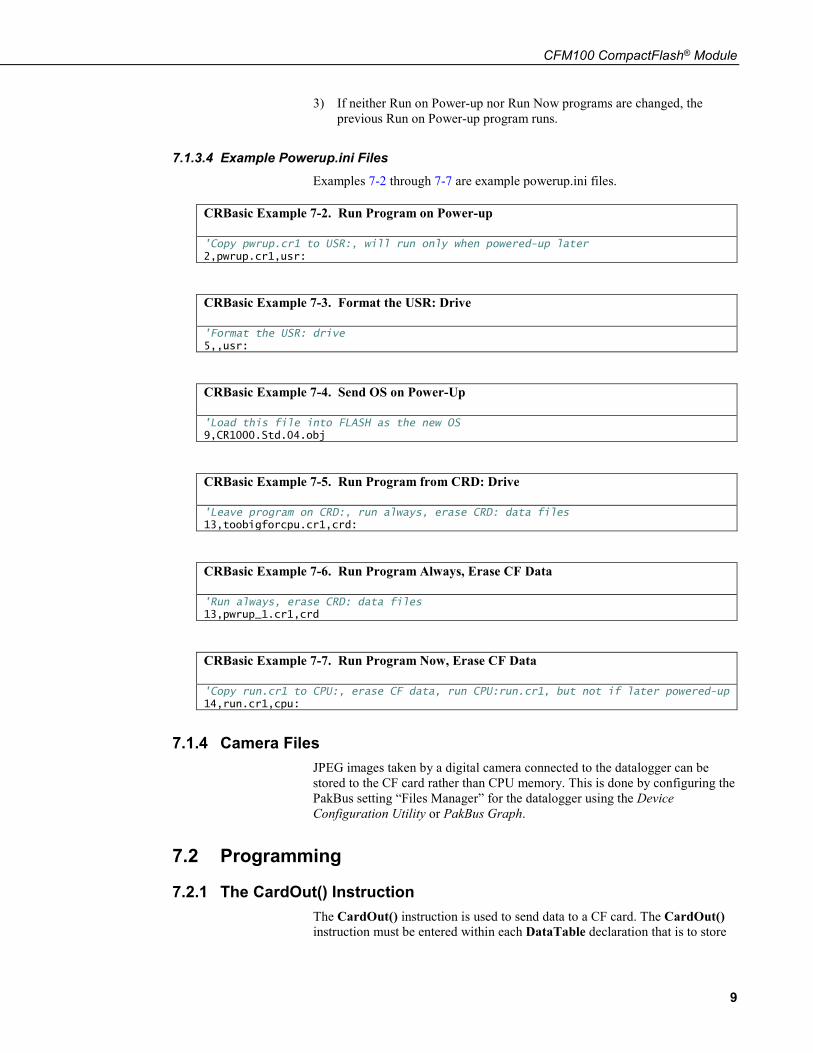
7.1.3.4 Example Powerup.ini Files Examples 7-2 through 7-7 are example powerup.ini files.
CRBasic Example 7-2. Run Program on Power-up
'Copy pwrup.cr1 to USR:, will run only when powered-up later 2,pwrup.cr1,usr:
CRBasic Example 7-3. Format the USR: Drive
'Format the USR: drive 5,,usr:
CRBasic Example 7-4. Send OS on Power-Up
'Load this file into FLASH as the new OS 9,CR1000.Std.04.obj
CRBasic Example 7-5. Run Program from CRD: Drive
'Leave program on CRD:, run always, erase CRD: data files 13,toobigforcpu.cr1,crd:
CRBasic Example 7-6. Run Program Always, Erase CF Data
'Run always, erase CRD: data files 13,pwrup_1.cr1,crd
CRBasic Example 7-7. Run Program Now, Erase CF Data
'Copy run.cr1 to CPU:, erase CF data, run CPU:run.cr1, but not if later powered-up 14,run.cr1,cpu:
7.1.4 Camera Files JPEG images taken by a digital camera connected to the datalogger can be stored to the CF card rather than CPU memory. This is done by configuring the PakBus setting “Files Manager” for the datalogger using the Device Configuration Utility or PakBus Graph.
7.2 Programming
7.2.1 The CardOut() Instruction The CardOut() instruction is used to send data to a CF card. The CardOut() instruction must be entered within each DataTable declaration that is to store
CFM100 CompactFlash® Module
10
data to the CF card. Data is stored to the card when a call is made to the data table.
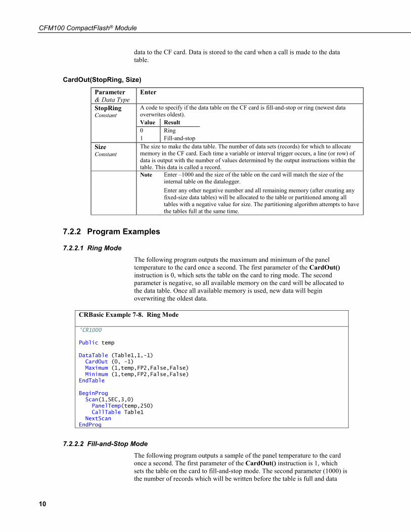
CardOut(StopRing, Size)
Parameter & Data Type
Enter
StopRing Constant
A code to specify if the data table on the CF card is fill-and-stop or ring (newest data overwrites oldest). Value Result 0 Ring 1 Fill-and-stop
Size Constant
The size to make the data table. The number of data sets (records) for which to allocate memory in the CF card. Each time a variable or interval trigger occurs, a line (or row) of data is output with the number of values determined by the output instructions within the table. This data is called a record. Note Enter –1000 and the size of the table on the card will match the size of the
internal table on the datalogger. Enter any other negative number and all remaining memory (after creating any fixed-size data tables) will be allocated to the table or partitioned among all tables with a negative value for size. The partitioning algorithm attempts to have the tables full at the same time.
7.2.2 Program Examples
7.2.2.1 Ring Mode The following program outputs the maximum and minimum of the panel temperature to the card once a second. The first parameter of the CardOut() instruction is 0, which sets the table on the card to ring mode. The second parameter is negative, so all available memory on the card will be allocated to the data table. Once all available memory is used, new data will begin overwriting the oldest data.
CRBasic Example 7-8. Ring Mode
'CR1000
Public temp
DataTable (Table1,1,-1) CardOut (0, -1) Maximum (1,temp,FP2,False,False) Minimum (1,temp,FP2,False,False) EndTable
BeginProg Scan(1,SEC,3,0) PanelTemp(temp,250) CallTable Table1
NextScan EndProg
7.2.2.2 Fill-and-Stop Mode The following program outputs a sample of the panel temperature to the card once a second. The first parameter of the CardOut() instruction is 1, which sets the table on the card to fill-and-stop mode. The second parameter (1000) is the number of records which will be written before the table is full and data
CFM100 CompactFlash® Module
11
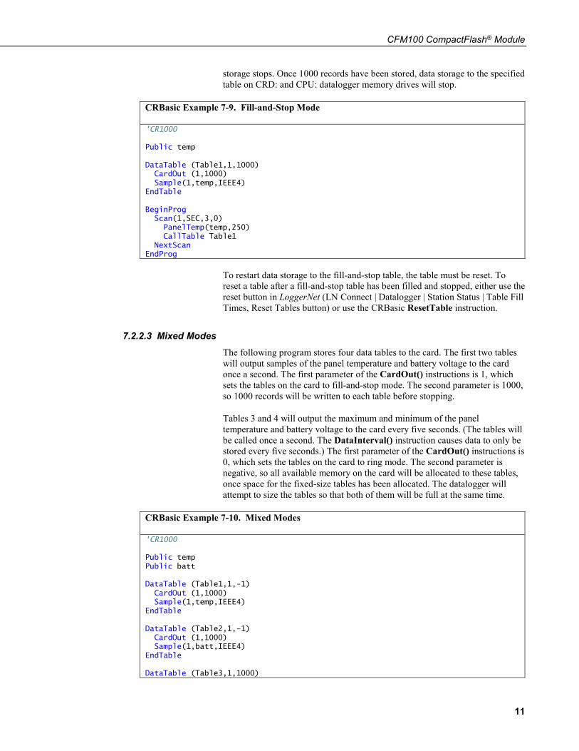
storage stops. Once 1000 records have been stored, data storage to the specified table on CRD: and CPU: datalogger memory drives will stop.
CRBasic Example 7-9. Fill-and-Stop Mode
'CR1000
Public temp
DataTable (Table1,1,1000) CardOut (1,1000) Sample(1,temp,IEEE4) EndTable
BeginProg Scan(1,SEC,3,0) PanelTemp(temp,250) CallTable Table1
NextScan EndProg
To restart data storage to the fill-and-stop table, the table must be reset. To reset a table after a fill-and-stop table has been filled and stopped, either use the reset button in LoggerNet (LN Connect | Datalogger | Station Status | Table Fill Times, Reset Tables button) or use the CRBasic ResetTable instruction.
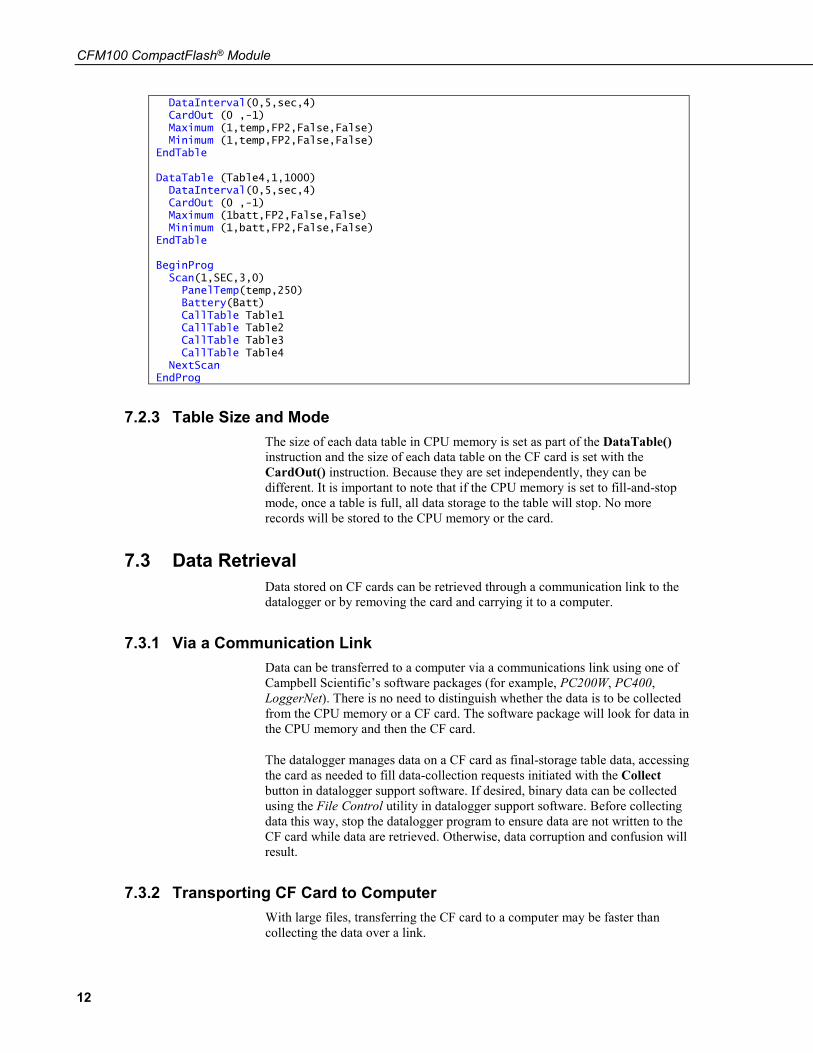
7.2.2.3 Mixed Modes The following program stores four data tables to the card. The first two tables will output samples of the panel temperature and battery voltage to the card once a second. The first parameter of the CardOut() instructions is 1, which sets the tables on the card to fill-and-stop mode. The second parameter is 1000, so 1000 records will be written to each table before stopping.
Tables 3 and 4 will output the maximum and minimum of the panel temperature and battery voltage to the card every five seconds. (The tables will be called once a second. The DataInterval() instruction causes data to only be stored every five seconds.) The first parameter of the CardOut() instructions is 0, which sets the tables on the card to ring mode. The second parameter is negative, so all available memory on the card will be allocated to these tables, once space for the fixed-size tables has been allocated. The datalogger will attempt to size the tables so that both of them will be full at the same time.
CRBasic Example 7-10. Mixed Modes
'CR1000
Public temp Public batt
DataTable (Table1,1,-1) CardOut (1,1000) Sample(1,temp,IEEE4) EndTable
DataTable (Table2,1,-1) CardOut (1,1000) Sample(1,batt,IEEE4) EndTable
DataTable (Table3,1,1000)
CFM100 CompactFlash® Module
12
DataInterval(0,5,sec,4) CardOut (0 ,-1) Maximum (1,temp,FP2,False,False) Minimum (1,temp,FP2,False,False) EndTable
DataTable (Table4,1,1000) DataInterval(0,5,sec,4) CardOut (0 ,-1) Maximum (1batt,FP2,False,False) Minimum (1,batt,FP2,False,False) EndTable
BeginProg Scan(1,SEC,3,0) PanelTemp(temp,250) Battery(Batt) CallTable Table1 CallTable Table2 CallTable Table3 CallTable Table4
NextScan EndProg
7.2.3 Table Size and Mode The size of each data table in CPU memory is set as part of the DataTable() instruction and the size of each data table on the CF card is set with the CardOut() instruction. Because they are set independently, they can be different. It is important to note that if the CPU memory is set to fill-and-stop mode, once a table is full, all data storage to the table will stop. No more records will be stored to the CPU memory or the card.
7.3 Data Retrieval Data stored on CF cards can be retrieved through a communication link to the datalogger or by removing the card and carrying it to a computer.
7.3.1 Via a Communication Link Data can be transferred to a computer via a communications link using one of Campbell Scientific’s software packages (for example, PC200W, PC400, LoggerNet). There is no need to distinguish whether the data is to be collected from the CPU memory or a CF card. The software package will look for data in the CPU memory and then the CF card.
The datalogger manages data on a CF card as final-storage table data, accessing the card as needed to fill data-collection requests initiated with the Collect button in datalogger support software. If desired, binary data can be collected using the File Control utility in datalogger support software. Before collecting data this way, stop the datalogger program to ensure data are not written to the CF card while data are retrieved. Otherwise, data corruption and confusion will result.
7.3.2 Transporting CF Card to Computer With large files, transferring the CF card to a computer may be faster than collecting the data over a link.
CFM100 CompactFlash® Module
13
Removing a card while it is active can cause garbled data and can actually damage the card. Do not switch off the CR1000 power if a card is present and active.
To remove a card, press the Initiate Removal button on the CFM100. The CR1000 or CR3000 will transfer any buffered data to the card and then power off. The Status LED will turn green when it is OK to remove the card. The card will be reactivated after 20 seconds if it is not removed.
When the CF card is inserted in a computer, the data files can be copied to another drive or used directly from the CF card just as one would from any other disk. In most cases, however, it will be necessary to convert the file format before using the data.
When dealing with large data files, it may be faster to use an external card reader (such as pn #17752) rather than a PC card slot.
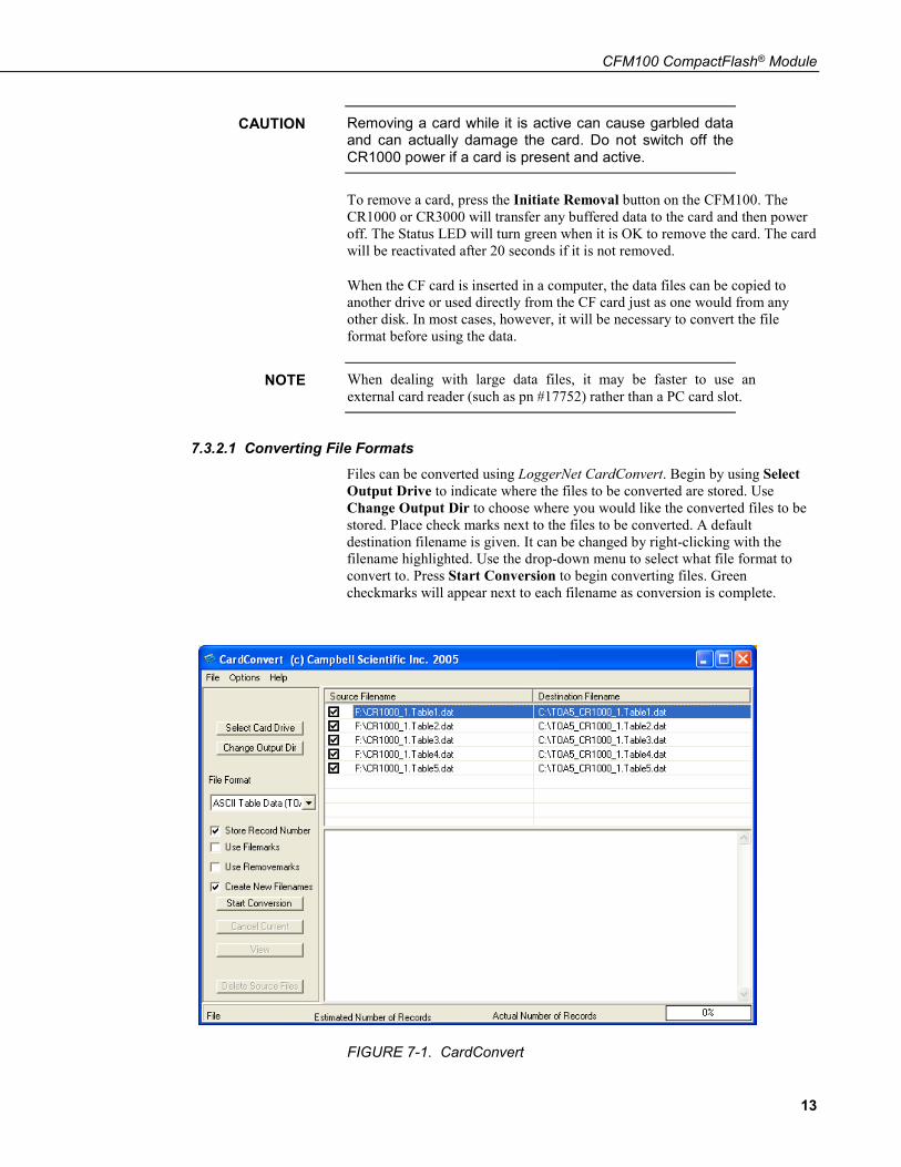
7.3.2.1 Converting File Formats Files can be converted using LoggerNet CardConvert. Begin by using Select Output Drive to indicate where the files to be converted are stored. Use Change Output Dir to choose where you would like the converted files to be stored. Place check marks next to the files to be converted. A default destination filename is given. It can be changed by right-clicking with the filename highlighted. Use the drop-down menu to select what file format to convert to. Press Start Conversion to begin converting files. Green checkmarks will appear next to each filename as conversion is complete.
FIGURE 7-1. CardConvert
CAUTION
NOTE
CFM100 CompactFlash® Module
14
7.3.2.2 Reinserting the Card If the same card is inserted again into the CFM100, the datalogger will store all data to the card that has been generated since the card was removed that is still in the CPU memory. If the data tables have been left on the card, new data will be appended to the end of the old files. If the data tables have been deleted, new ones will be generated.
Check the status of the card before leaving the datalogger. If a CF card was not properly accepted, the CFM100 will flash orange. In that case, the CF card needs to be reformatted and all data erased. Formatting or erasing a CF card can be done on a PC or datalogger. The procedure for formatting a CF card is explained in Appendix A, CF Card Maintenance (p. A-1).
7.3.2.3 Card Swapping When transporting a CF card to a computer to retrieve data, most users will want to use a second card to ensure that no data is lost. For this method of collection, use the following steps.
1. Insert formatted card (“CF-A”) in CFM100 attached to datalogger.
2. Send program containing CardOut() instruction(s).
3. When ready to retrieve data, press the Initiate Removal button to removecard. The LED will show red while the most current data is stored to thecard and then will turn green. Eject card while LED is green.
4. Put in clean card (“CF-B”).
5. Use CardConvert to copy data from CF-A to PC and convert. The defaultCardConvert filename will be TOA5_stationname_tablename.dat. Oncethe data is copied, use Windows Explorer to delete all data files from thecard. NOTE: Windows98 and WindowsME users need to shift-delete tocompletely delete files. Using standard delete may create an invisiblerecycle bin on the CF card.
6. At the next card swap, eject CF-B and insert the clean CF-A.
7. Running CardConvert on CF-B will result in separate data files containingrecords since CF-A was ejected. CardConvert can increment the filenameto TOA5_stationname_tablename_0.dat.
8. The data files can be joined using a software utility such as WordPad orExcel.
CardConvert File CF-A Record Numbers CF-B Record Numbers
TOA5_tablename.dat 0-100
TOA5_tablename.dat 101-1234
TOA5_tablename.dat 1235-….
NOTE
A-1
Appendix A. CF Card Maintenance
A.1 Formatting CF CardThe CF card can be formatted using 1) Windows Explorer, 2) the CR1000KD, or 3) LoggerNet File Control.
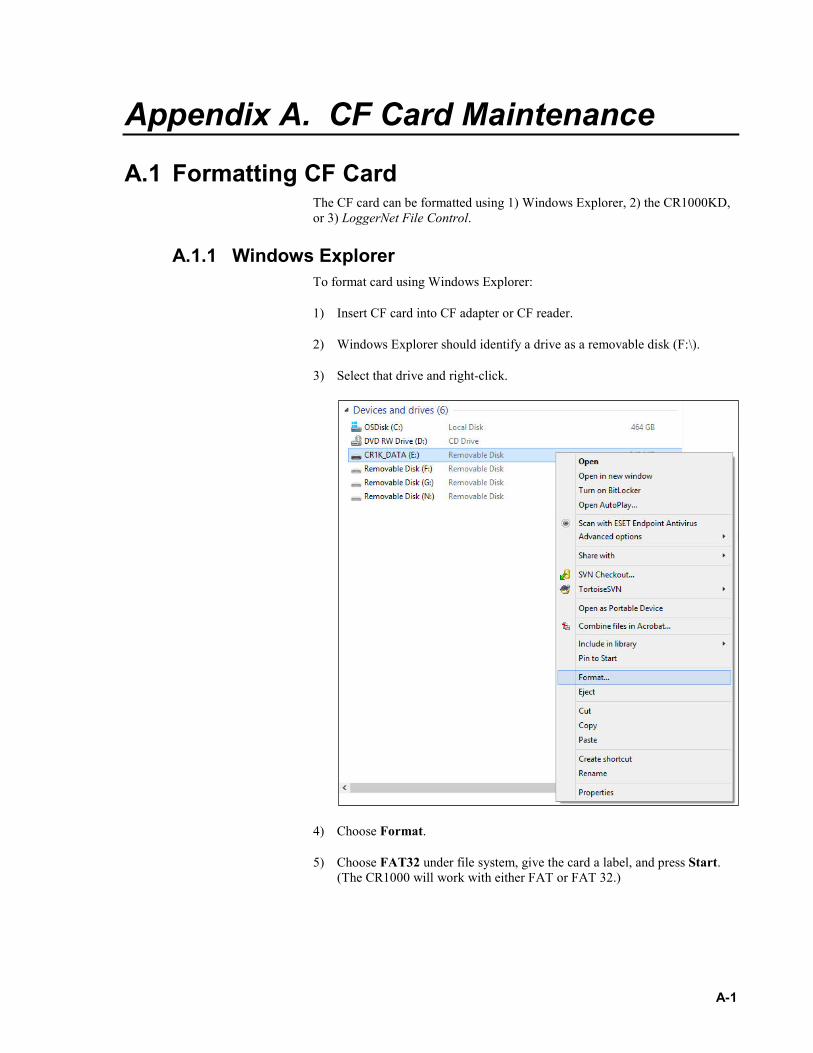
A.1.1 Windows ExplorerTo format card using Windows Explorer:
1) Insert CF card into CF adapter or CF reader.
2) Windows Explorer should identify a drive as a removable disk (F:\).
3) Select that drive and right-click.
4) Choose Format.
5) Choose FAT32 under file system, give the card a label, and press Start.(The CR1000 will work with either FAT or FAT 32.)

Appendix A. CF Card Maintenance
A-2
A.1.2 CR1000KDTo format card using the CR1000KD:
1) Insert CF card into CFM100.
2) From the main menu of CR1000KD, choose PCCard.
3) Choose Format Card.
4) Press Yes to proceed.
A.1.3 LoggerNet File ControlTo format card using LoggerNet File Control:
1) Insert CF card into CFM100.
2) Use LoggerNet to connect to datalogger
Appendix A. CF Card Maintenance
A-3
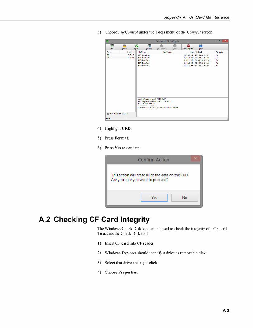
3) Choose FileControl under the Tools menu of the Connect screen.
4) Highlight CRD.
5) Press Format.
6) Press Yes to confirm.
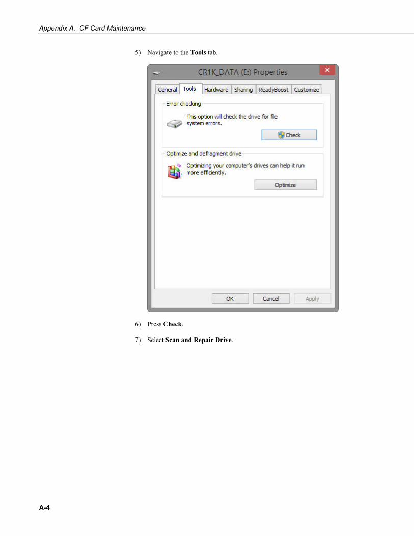
A.2 Checking CF Card IntegrityThe Windows Check Disk tool can be used to check the integrity of a CF card. To access the Check Disk tool:
1) Insert CF card into CF reader.
2) Windows Explorer should identify a drive as removable disk.
3) Select that drive and right-click.
4) Choose Properties.
Appendix A. CF Card Maintenance
A-4
5) Navigate to the Tools tab.
6) Press Check.
7) Select Scan and Repair Drive.

Campbell Scientific Companies
Campbell Scientific, Inc. 815 West 1800 North Logan, Utah 84321 UNITED STATES
www.campbellsci.com • [email protected]
Campbell Scientific Africa Pty. Ltd. PO Box 2450
Somerset West 7129 SOUTH AFRICA
www.campbellsci.co.za • [email protected]
Campbell Scientific Southeast Asia Co., Ltd. 877/22 Nirvana@Work, Rama 9 Road
Suan Luang Subdistrict, Suan Luang District Bangkok 10250
THAILAND www.campbellsci.asia • [email protected]
Campbell Scientific Australia Pty. Ltd. PO Box 8108
Garbutt Post Shop QLD 4814 AUSTRALIA
www.campbellsci.com.au • [email protected]
Campbell Scientific (Beijing) Co., Ltd. 8B16, Floor 8 Tower B, Hanwei Plaza
7 Guanghua Road Chaoyang, Beijing 100004
P.R. CHINA www.campbellsci.com • [email protected]
Campbell Scientific do Brasil Ltda. Rua Apinagés, nbr. 2018 ─ Perdizes CEP: 01258-00 ─ São Paulo ─ SP
BRASIL www.campbellsci.com.br • [email protected]
Campbell Scientific Canada Corp. 14532 – 131 Avenue NW Edmonton AB T5L 4X4
CANADA www.campbellsci.ca • [email protected]
Campbell Scientific Centro Caribe S.A. 300 N Cementerio, Edificio Breller
Santo Domingo, Heredia 40305 COSTA RICA
www.campbellsci.cc • [email protected]
Campbell Scientific Ltd. Campbell Park
80 Hathern Road Shepshed, Loughborough LE12 9GX
UNITED KINGDOM www.campbellsci.co.uk • [email protected]
Campbell Scientific Ltd. 3 Avenue de la Division Leclerc
92160 ANTONY FRANCE
www.campbellsci.fr • [email protected]
Campbell Scientific Ltd. Fahrenheitstraße 13
28359 Bremen GERMANY
www.campbellsci.de • [email protected]
Campbell Scientific Spain, S. L. Avda. Pompeu Fabra 7-9, local 1
08024 Barcelona SPAIN
www.campbellsci.es • [email protected]
Please visit www.campbellsci.com to obtain contact information for your local US or international representative.