Embed Size (px)
Citation preview

1
[Introduction to be inserted] 2 3
Radiocommunication Study Groups
DRAFT Document 5D/IEEE-xx-E xx March 2011
Received:
Reference: Question ITU-R 229-2/5 English only TECHNOLOGY ASPECTS
Institute of Electrical and Electronics Engineers (IEEE)
PROPOSED MODIFICATIONS TO THE WORKING DOCUMENT TOWARDS PDNR M.[IMT.RSPEC]
IEEE L802.16-10/0113d7

- 2 - DRAFT 5D/IEEE-XX-E
1
1 Introduction 2
International Mobile Telecommunications-Advanced (IMT-Advanced) systems are mobile systems that include the 3 new capabilities of IMT that go beyond those of IMT-2000. Such systems provide access to a wide range of 4 telecommunication services including advanced mobile services, supported by mobile and fixed networks, which are 5 increasingly packet-based. 6
IMT-Advanced systems support low to high mobility applications and a wide range of data rates in accordance with 7 user and service demands in multiple user environments. IMT-Advanced also has capabilities for high-quality 8 multimedia applications within a wide range of services and platforms providing a significant improvement in 9 performance and quality of service. 10
The key features of IMT-Advanced are: 11
– a high degree of commonality of functionality worldwide while retaining the flexibility to support a wide 12 range of services and applications in a cost efficient manner; 13
– compatibility of services within IMT and with fixed networks; 14
– capability of interworking with other radio access systems; 15
– high-quality mobile services; 16
– user equipment suitable for worldwide use; 17
– user-friendly applications, services and equipment; 18
– worldwide roaming capability; 19
– enhanced peak data rates to support advanced services and applications (100 Mbit/s for high and 1 Gbit/s 20
for low mobility were established as targets for research)1. 21
These features enable IMT-Advanced to address evolving user needs. 22
The capabilities of IMT-Advanced systems are being continuously enhanced in line with user trends and technology 23 developments. 24
2 Scope 25
This Recommendation identifies the detailed terrestrial radio interface specifications of IMT-Advanced. 26
These radio specifications detail the design features and design parameters of IMT-Advanced. This 27 Recommendation includes the capability to ensure worldwide compatibility, international roaming, and access to 28 high-speed data services. 29
[Editor’s note: the previous paragraph might need additional consideration to reflect some of the views expressed, 30 e.g., in Res 57, M.1822, and M.2133] 31
____________________ 1 Data rates sourced from Recommendation ITU-R M.1645.
SWG IMT Specifications
WORKING DOCUMENT TOWARDS A PRELIMINARY DRAFT NEW RECOMMENDATION ITU-R M.[IMT.RSPEC]
Detailed specifications of the terrestrial radio interfaces of IMT-Advanced

- 3 - DRAFT 5D/IEEE-XX-E
3 Related ITU-R Recommendations and Reports 1
Recommendation ITU-R M.1036 2
Recommendation ITU-R M.1457 3
Recommendation ITU-R M.1579 4
Recommendation ITU-R M.1580 5
Recommendation ITU-R M.1581 6
Recommendation ITU-R M.1645 7
Recommendation ITU-R M.1768 8
Recommendation ITU-R M.1822 9
Recommendation ITU-T Q.1741 10
Recommendation ITU-T Q.1742 11
Report ITU-R M.2038 12
Report ITU-R M.2072 13
Report ITU-R M.2074 14
Report ITU-R M.2078 15
Report ITU-R M.2079 16
Report ITU-R M.2133. 17
Report ITU-R M.2134 18
Report ITU-R M.2135-1. 19
Report ITU-R M.[IMT.RADIO]. 20
4 Acronyms and abbreviations 21
[Editor’s Note: to be added] 22 23

- 4 - DRAFT 5D/IEEE-XX-E
1
5 Notings and considerations 2
The ITU-R Radiocommunication Assembly, 3
noting 4
a) Report ITU-R M.[IMT.RADIO] which contains the outcome and conclusions of Step 4 through 7 of the 5 IMT-Advanced process, including the evaluation and consensus building, and provides the characteristics of the 6 IMT-Advanced terrestrial radio interfaces, 7
considering 8
a) the possible involvement of several types of networks; 9
b) the increasing technical developments and opportunities; 10
c) the need of many users for services which are not bounded by geography or operators; 11
d) the necessity of priority services (e.g. emergency calls shall be supported as higher priority than other 12 commercial services); 13
e) that the services supported by IMT will be operated in an environment which requires recognition of the 14 following factors: 15
e-1) low cost: Users want diverse, affordable, and convenient mobile services. Such demands will be realized 16 by development of technology that will reduce the cost per packet; 17
e-2) large effective bandwidths: to support the very high data rates that will likely be required by the various 18 services offered, allowances must be made for either much larger single carrier bandwidths (even as spectral 19 efficiencies increase) or aggregation of RF carriers; 20
e-3) high data rate: services such as video phone, streaming, and video-on-demand, which are currently 21 available via wired networks will be required to be supported via wireless networks with higher broadband capacity 22 with anytime, anywhere availability; 23
e-4) convergence: the rapid development of information technology (IT), including the Internet, has resulted in 24 the aggregation and convergence of various networks and digital devices. In addition to the aggregation of data and 25 voice, the integration of wired and wireless communications is ongoing; 26
e-5) wide range of terminals: a wide range of terminals is desired for future mobile services. Some users may 27 need an affordable voice-centric terminal while other users would prefer a versatile mobile phone that could provide 28 not only traditional functions like telephony, but also utilities such as a digital camera, music and movie player, map 29 guidance, e-Wallet, etc. For connecting to the electric, electronic, and mechanical machine surrounding user, short-30 range communication devices could be merged to the terminals. 31
32

- 5 - DRAFT 5D/IEEE-XX-E
1
6 Recommendation 2
The ITU Radiocommunication Assembly, 3
recommends 4
1) the radio interface specifications in the Annexes below as the terrestrial radio interfaces of IMT-Advanced: 5
Annex A: Specification of the LTE-Advanced2 radio interface technology 6
Annex B: Specification of the WirelessMAN-Advanced3 radio interface technology; 7
2) the detailed information provided or referenced in these Annexes as the complete set of standards for the 8 terrestrial radio interfaces of IMT-Advanced. 9
10
Annex A 11 12
Specification of the LTE-Advanced4 radio interface technology 13
Background 14
IMT-Advanced is a system with global development activity and the IMT-Advanced terrestrial radio interface 15 specifications identified in this Recommendation have been developed by the ITU in collaboration with the GCS 16 Proponents and the Transposing Organizations. It is noted from document ITU-R IMT-ADV/24, that: 17
- The GCS Proponent must be one of the RIT/SRIT Proponents for the relevant technology, and must have legal 18 authority to grant to ITU-R the relevant legal usage rights to the relevant specifications provided within a GCS 19 corresponding to a technology in Recommendation ITU-R M.[IMT.RSPEC] 20
- A Transposing Organization must have been authorized by the relevant GCS Proponent to produce transposed 21 standards for a particular technology, and must have the relevant legal usage rights. 22
It is further noted that GCS Proponents and Transposing Organizations must also qualify appropriately under the 23 auspices of ITU-R Resolution 9-3 and the ITU-R “Guidelines for the contribution of material of other organizations 24 to the work of the Study Groups and for inviting other organizations to take part in the study of specific matters 25 (Resolution ITU-R 9-3)”. 26
The ITU has provided the global and overall framework and requirements, and has developed the Global Core 27 Specification jointly with the GCS Proponent. The detailed standardization has been undertaken within the 28 recognized Transposing Organizations which operate in concert with the GCS Proponent. This Recommendation 29 therefore makes extensive use of references to externally developed specifications. 30
This approach was considered to be the most appropriate solution to enable completion of this Recommendation 31 within the aggressive schedules set by the ITU and by the needs of administrations, operators and manufacturers. 32
This Recommendation has therefore been constructed to take full advantage of this method of work and to allow the 33 global standardization time-scales to be maintained. The main body of this Recommendation has been developed by 34 the ITU, with each Annex containing references pointing to the location of the more detailed information. 35
____________________ 2 Developed by 3GPP as LTE Release 10 and Beyond (LTE-Advanced). 3 Developed by IEEE as the WirelessMAN-Advanced specification incorporated in IEEE Std 802.16 beginning with
approval of IEEE Std 802.16m. 4 Developed by 3GPP as LTE Release 10 and Beyond (LTE-Advanced).

- 6 - DRAFT 5D/IEEE-XX-E
This Annex A contains the detailed information developed by the ITU and “ARIB, ATIS, CCSA, ETSI, TTA, and 1 TTC on behalf of 3GPP” (the GCS Proponent) and [TBD] (the Transposing Organizations). Such use of 2 referencing has enabled timely completion of the high-level elements of this Recommendation, with change control 3 procedures, transposition, and public enquiry procedures being undertaken within the external organization. 4
The detailed specifications received from “ARIB, ATIS, CCSA, ETSI, TTA, and TTC on behalf of 3GPP” (the GCS 5 Proponent) and [TBD] (the Transposing Organizations) have generally been adopted unchanged, recognizing the 6 need to minimize duplication of work, and the need to facilitate and support an on-going maintenance and update 7 process. 8
This general agreement, that the detailed specifications of the radio interface should to a large extent be achieved by 9 reference to the work of external organizations, highlights not only the ITU’s significant role as a catalyst in 10 stimulating, coordinating and facilitating the development of advanced telecommunications technologies, but also its 11 forward-looking and flexible approach to the development of this and other telecommunications standards for the 12 21st century. 13
A more detailed understanding of the process for the development of this Recommendation may be found in 14 Document ITU-R IMT-ADV/24. 15
A.1 Overview of the radio interface technology 16
[Editor’s Note: to be filled with stakeholder’s input(s)] 17
A.2 Detailed specification of the radio interface technology 18
Detailed specifications described in this Recommendation are developed around a “Global Core Specification” 19
(GCS)5, which is related to externally developed materials incorporated by specific references for a specific 20 technology. The process and use of the GCS, references, and related notifications and certifications are found as 21
IMT-ADV/246 22
The standards contained in this section are derived from the global core specifications for IMT-Advanced contained 23 at http://ties.itu.int/u/itu-r/ede/rsg5/xxxxx/xxx/xxxxxxxx/. The following notes apply to the sections below, where 24 indicated: 25
1) The [relevant][TBD] (the Transposing Organisations) should make their reference material available 26 from their web site. 27
2) This information was supplied by the Transposing Organizations and relates to their own deliverables of 28 the transposed global core specification. 29
[Editor’s note: the above notes will be revisited when the final version of IMT.RSPEC will be finalised] 30
[Editor’s Note: to be filled with stakeholder’s input(s)] 31
32
____________________ 5 A “GCS” (Global Core Specification) is the set of specifications that defines a single RIT, an SRIT, or a RIT
within an SRIT. 6 ADV/24 is available on the ITU-R WP 5D web page under the link “IMT-Advanced documents”
(http://www.itu.int/md/R07-IMT.ADV-C-0024/e

- 7 - DRAFT 5D/IEEE-XX-E
Annex B 1 2
Specification of the WirelessMAN-Advanced7 radio access interface technology 3
Background 4
IMT-Advanced is a system with global development activity and the IMT-Advanced terrestrial radio interface 5 specifications identified in this Recommendation have been developed by the ITU in collaboration with the GCS 6 Proponents and the Transposing Organizations. It is noted from document ITU-R IMT-ADV/24, that: 7
- The GCS Proponent must be one of the RIT/SRIT Proponents for the relevant technology, and must have legal 8 authority to grant to ITU-R the relevant legal usage rights to the relevant specifications provided within a GCS 9 corresponding to a technology in Recommendation ITU-R M.[IMT.RSPEC] 10
- A Transposing Organization must have been authorized by the relevant GCS Proponent to produce transposed 11 standards for a particular technology, and must have the relevant legal usage rights. 12
It is further noted that GCS Proponents and Transposing Organizations must also qualify appropriately under the 13 auspices of ITU-R Resolution 9-3 and the ITU-R “Guidelines for the contribution of material of other organizations 14 to the work of the Study Groups and for inviting other organizations to take part in the study of specific matters 15 (Resolution ITU-R 9-3)”. 16
The ITU has provided the global and overall framework and requirements, and has developed the Global Core 17 Specification jointly with the GCS Proponent. The detailed standardization has been undertaken within the 18 recognized Transposing Organizations which operate in concert with the GCS Proponent. This Recommendation 19 therefore makes extensive use of references to externally developed specifications. 20
This approach was considered to be the most appropriate solution to enable completion of this Recommendation 21 within the aggressive schedules set by the ITU and by the needs of administrations, operators and manufacturers. 22
This Recommendation has therefore been constructed to take full advantage of this method of work and to allow the 23 global standardization time-scales to be maintained. The main body of this Recommendation has been developed by 24 the ITU, with each Annex containing references pointing to the location of the more detailed information. 25
26
____________________ 7 Developed by IEEE as the WirelessMAN-Advanced specification incorporated in IEEE Std 802.16 beginning with
approval of IEEE Std 802.16m.

- 8 - DRAFT 5D/IEEE-XX-E
1
This Annex BA contains the detailed information developed by the ITU and “IEEE” (the GCS Proponent) and 2 [TBD] (the Transposing Organizations). Such use of referencing has enabled timely completion of the high-level 3 elements of this Recommendation, with change control procedures, transposition, and public enquiry procedures 4 being undertaken within the external organization. 5
The detailed specifications received from “IEEE” (the GCS Proponent) and [TBD] (the Transposing 6 Organizations) have generally been adopted unchanged, recognizing the need to minimize duplication of work, and 7 the need to facilitate and support an on-going maintenance and update process. 8
This general agreement, that the detailed specifications of the radio interface should to a large extent be achieved by 9 reference to the work of external organizations, highlights not only the ITU’s significant role as a catalyst in 10 stimulating, coordinating and facilitating the development of advanced telecommunications technologies, but also its 11 forward-looking and flexible approach to the development of this and other telecommunications standards for the 12 21st century. 13
A more detailed understanding of the process for the development of this Recommendation may be found in 14 Document ITU-R IMT-ADV/24. 15
B.1 Overview of the radio interface technology 16
[Editor’s Note: to be filled GCS Proponents’ input(s) – the text is anticipated to be approx 10 pages] 17
The WirelessMAN-Advanced radio interface specification is developed by IEEE. A complete end-to-end 18 specification based on WirelessMAN-Advanced developed by the WiMAX Forum is called WiMAX 2. 19
The following clauses provide an overview of the WirelessMAN-Advanced radio interface technology. 20
B.1.1Protocol Structure 21
The MAC layer is composed of two sublayers: convergence sublayer (CS) and MAC common part sublayer (MAC 22 CPS). For convenience, the MAC CPS functions are classified into two groups based on their characteristics as 23 shown in Figure 1. The upper and lower classes are referred to as resource control and management functional group 24 and medium access control functional group, respectively. The control plane functions and data plane functions are 25 also separately classified. This would allow more organized, efficient, structured method for specifying the MAC 26 services in the WirelessMAN-Advanced standard specification. As shown in Figure 1, the radio resource control and 27 management functional group comprises several functional blocks including 28
29 - Radio resource management adjusts radio network parameters related to the traffic load, and also 30
includes the functions of load control (load balancing), admission control and interference control. 31 - Mobility management scans neighbour BSs and decides whether MS should perform handover operation. 32 - Network-entry management controls initialization and access procedures and generates management 33
messages during initialization and access procedures. 34 - Location management supports location based service (LBS), generates messages including the LBS 35
information, and manages location update operation during idle mode. 36 - Idle mode management controls idle mode operation, and generates the paging advertisement message 37
based on paging message from paging controller in the core network. 38 - Security management performs key management for secure communication. Using managed key, traffic 39
encryption/decryption and authentication are performed. 40 - System configuration management manages system configuration parameters, and generates broadcast 41
control messages such as Superframe Header. 42 - Multicast and broadcast service (MBS) controls and generates management messages and data 43
associated with MBS. 44 - Service flow and connection management allocates Station Identifier (STID) and Flow Identifiers (FIDs) 45
during access/handover service flow creation procedures. 46
The medium access control functional group includes functional blocks which are related to physical layer and link 47 controls such as 48

- 9 - DRAFT 5D/IEEE-XX-E
1 - PHY control performs PHY signalling such as ranging, channel quality measurement/feedback (CQI), and 2
HARQ ACK or NACK signalling. 3 - Control signalling generates resource allocation messages such as advanced medium access protocol as 4
well as specific control signalling messages. 5 - Sleep mode management handles sleep mode operation and generates management messages related to 6
sleep operation, and may communicate with the scheduler block in order to operate properly according to 7 sleep period. 8
- Quality-of-service (QoS) performs rate control based on QoS input parameters from connection 9 management function for each connection. 10
- Scheduling and resource multiplexing schedules and multiplexes packets based on properties of 11 connections. 12
The data plane includes functional blocks such as 13
14 - Fragmentation/packing performs fragmentation or packing of MAC Service Data Units (MSDU) based 15
on input from the scheduling and resource multiplexing block. 16 - Automatic Repeat Request (ARQ) performs MAC ARQ function. For ARQ-enabled connections, a 17
logical ARQ block is generated from fragmented or packed MSDUs of the same flow and sequentially 18 numbered. 19
- MAC Protocol Data Unit (PDU) formation constructs MAC PDU (MPDU) such that BS/MS can 20 transmit user traffic or management messages into PHY channels. 21
22
Figure 1: IEEE WirelessMAN-Advanced Protocol Stack 23
The WirelessMAN-Advanced protocol structure is similar to that of IMT-2000 OFDMA TDD WMAN with some 24 additional functional blocks for new features including the following: 25
- Relay functions perform relay functionalities and packet routing in relay networks 26 - Self Organization and Self-optimization functions performs the self-configuration and self-optimization 27
procedures based on MS measurement reports. 28

- 10 - DRAFT 5D/IEEE-XX-E
- Multi-carrier functions enable control and operation of a number of adjacent or non-adjacent RF carriers 1 where the RF carriers can be assigned to unicast and/or multicast and broadcast services. A single MAC 2 instantiation will be used to control several physical layers. The load balancing functions and RF carrier 3 mapping and control are performed via radio resource control and management functional class. The 4 carriers utilized in a multi-carrier system, from perspective of a mobile station can be divided into two 5 categories: 6
o A primary RF carrier is the carrier that is used by the BS and the MS to exchange traffic and full 7 PHY/MAC control information. The primary carrier delivers control information for proper MS 8 operation, such as network entry. Each mobile station is assigned only one primary carrier in a cell. 9
o A secondary RF carrier is an additional carrier which the BS may use for traffic allocations for mobile 10 stations capable of multi-carrier support. The secondary carrier may also include dedicated control 11 signalling to support multi-carrier operation. 12
Based on the primary and/or secondary usage, the carriers of a multi-carrier system may be configured 13 differently as follows: 14
o Fully configured carrier: A carrier for which all control channels including synchronization, 15 broadcast, multicast and unicast control signalling are configured. Furthermore, information and 16 parameters regarding multi-carrier operation and the other carriers can also be included in the control 17 channels. A primary carrier is fully configured, while a secondary carrier may be fully or partially 18 configured depending on usage and deployment model. 19
o Partially configured carrier: A carrier with only essential control channel configuration to support 20 traffic exchanges during multi-carrier operation. 21
- Multi-Radio Coexistence functions provide protocols for the multi-radio coexistence functional blocks of 22 MS and BS to communicate with each other via air interface. MS generates management messages to 23 report the information about its co-located radio activities obtained from inter-radio interface and BS 24 generates management messages to respond with the corresponding actions to support multi-radio 25 coexistence operation. Furthermore, the multi-radio coexistence functional block at BS communicates with 26 the scheduler functional block to operate properly according to the reported co-located coexistence 27 activities. 28
B.1.2 Mobile Station State Diagram 29
The WirelessMAN-Advanced mobile state diagram (i.e., a finite set of states and procedures between which the 30 mobile station transit when operating in the system to receive and transmit data) is shown in Figure 2: 31
- Initialization State: a state where a mobile station without any connection performs cell selection by 32 scanning and synchronizing to a BS preamble and acquires the system configuration information through 33 the superframe header. 34
- Access State: a state where the mobile station performs network entry to the selected base station. The 35 mobile station performs the initial ranging process in order to obtain uplink synchronization. Then the MS 36 performs basic capability negotiation with the BS. The MS later performs the authentication and 37 authorization procedure. Next, the MS performs the registration process. The mobile station receives 38 WirelessMAN-Advanced specific user identification as part of Access State procedures. The IP address 39 assignment may follow using appropriate procedures. 40
- Connected State: a state consisting of the following modes: Sleep Mode, Active Mode, and Scanning 41 Mode. During Connected State, the MS maintains at least one transport connection and two management 42 connections as established during Access State, while the MS and BS may establish additional transport 43 connections. In order to reduce power consumption of the MS, the MS or BS can request a transition to 44 sleep mode. Also, the MS can scan neighbour base stations to reselect a cell which provides more robust 45 and reliable services. 46

- 11 - DRAFT 5D/IEEE-XX-E
Idle State: a state comprising two separate modes, paging available mode and paging unavailable mode. During Idle 1 State, the MS may save power by switching between Paging Available mode and Paging Unavailable mode. In the 2 Paging Available mode, the MS may be paged by the BS. If the MS is paged, it transitions to the Access State for its 3 network re-entry. The MS performs location update procedure during Idle State. 4
5
Figure 2: Mobile Station State Diagram 6
Although both normal and fast network re-entry processes are shown as transition from the Idle State to the Access 7 State in Figure 2, there are differences that differentiate the two processes. The network re-entry is similar to 8 network entry, except it may be shortened by the providing the target BS with MS information through paging 9 controller or other network entity over the backhaul. 10
B.1.3 Overview of Physical Layer 11
B.1.3.1 Multiple Access Schemes 12
WirelessMAN-Advanced uses OFDMA as the multiple-access scheme in downlink and uplink. It further supports 13 both TDD and FDD duplex schemes including H-FDD operation of the mobile stations in the FDD networks. The 14 frame structure attributes and baseband processing are common for both duplex schemes. The OFDMA parameters 15 are summarized in Table 1. Tone dropping at both edges of the frequency band based on 10 and 20 MHz systems 16 can be used to support other bandwidths. In Table 1, TTG and RTG denote transmit/receive and receive/transmit 17 transition gaps, respectively. 18

- 12 - DRAFT 5D/IEEE-XX-E
B.1.3.2 Frame Structure 1
A superframe is a collection of consecutive equally-sized radio frames whose beginning is marked with a 2 superframe header. The superframe header carries short-term and long-term system configuration information. 3
In order to decrease the air-link access latency, the radio frames are further divided into a number of subframes 4 where each subframe comprises of an integer number of OFDM symbols. The transmission time interval is defined 5 as the transmission latency over the air-link and is equal to a multiple of subframe length (default is one subframe). 6 There are four types of subframes: 1) type-1 subframe, which consists of six OFDM symbols, 2) type-2 subframe, 7 which consists of seven OFDM symbols, 3) type-3 subframe which consists of five OFDM symbols, and 4) type-4 8 subframe, which consists of nine OFDM symbols. In the basic frame structure shown in Figure 3, superframe length 9 is 20 ms (comprised of four radio frames), radio frame size is 5 ms (comprised of eight subframes), and subframe 10 length is 0.617 ms. 11
Table 1: OFDMA Parameters 12
Nominal channel bandwidth (MHz) 5 7 8.75 10 20 Sampling factor 28/25 8/7 8/7 28/25 28/25
Sampling frequency (MHz) 5.6 8 10 11.2 22.4 FFT size 512 1024 1024 1024 2048
Subcarrier spacing (kHz) 10.94 7.81 9.76 10.94 10.94 Useful symbol time Tu (µs) 91.429 128 102.4 91.429 91.429
Symbol time Ts (µs) 102.857 144 115.2 102.857 102.857
Number of OFDM symbols per 5ms frame 48 34 43 48 48
FDD
Idle time (µs) 62.857 104 46.40 62.857 62.857 Number of OFDM
symbols per 5ms frame 47 33 42 47 47
CP Tg=1/8 Tu
TDD TTG + RTG (µs) 165.714 248 161.6 165.714 165.714
Symbol time Ts (µs) 97.143 136 108.8 97.143 97.143 Number of OFDM
symbols per 5ms frame 51 36 45 51 51 FDD
Idle time (µs) 45.71 104 104 45.71 45.71 Number of OFDM
symbols per 5ms frame 50 35 44 50 50
CP Tg=1/16 Tu
TDD TTG + RTG (µs) 142.853 240 212.8 142.853 142.853
Symbol Time Ts (µs) 114.286 160 128 114.286 114.286 Number of OFDM
symbols per 5ms frame 43 31 39 43 43 FDD
Idle time (µs) 85.694 40 8 85.694 85.694 Number of OFDM
symbols per 5ms frame 42 30 37 42 42
CP Tg=1/4 Tu
TDD TTG + RTG (µs) 199.98 200 264 199.98 199.98
The concept of time zones applies to both TDD and FDD systems. These time zones are time-division multiplexed 13 across time domain in the DL to support both new and legacy mobile stations. For UL transmissions both time and 14 frequency-division multiplexing approaches can be used to support legacy and new terminals. The non-backward 15 compatible improvements and features are restricted to the new zones. All backward compatible features and 16 functions are used in the legacy zones. 17

- 13 - DRAFT 5D/IEEE-XX-E
1
Figure 3: Basic Frame Structure 2
The support for multiple RF carriers can be accommodated with the same frame structure used for single carrier 3 operation. All RF carriers are time aligned at the frame, subframe, and symbol level. Alternative frame structures for 4 CP=1/16 and CP=1/4 are used that incorporate different number of OFDM symbols in certain subframes or different 5 number of subframes per frame. 6
B.1.3.3 Physical and Logical Resource Blocks 7
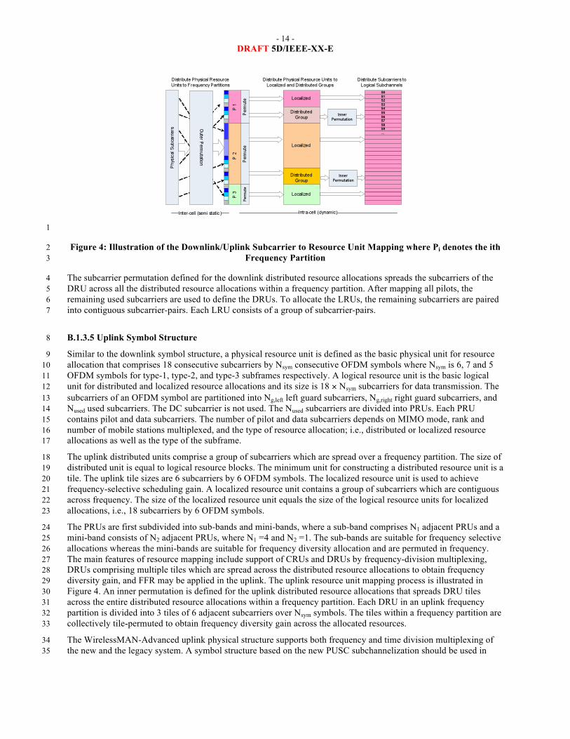
The downlink/uplink subframes are divided into a number of frequency partitions, where each partition consists of a 8 set of physical resource units over the available number of OFDM symbols in the subframe. Each frequency 9 partition can include localized and/or distributed physical resource units. Frequency partitions can be used for 10 different purposes such as fractional frequency reuse (FFR). The downlink/uplink resource petitioning and mapping 11 is illustrated in Figure 4. 12
B.1.3.4 Downlink Symbol Structure 13
A physical resource unit (PRU) is the basic physical unit for resource allocation that comprises 18 contiguous 14 subcarriers by Nsym contiguous OFDM symbols where Nsym is 6, 7, 5, or 9 OFDM symbols for type-1, type-2, type-15 3, and type-4 subframes, respectively. A logical resource unit (LRU) is the basic logical unit for distributed and 16 localized resource allocations. A logical resource unit comprises of 18×Nsym subcarriers. 17
Distributed resource units (DRU) are used to achieve frequency diversity gain. A distributed resource unit contains a 18 group of subcarriers which are spread across a frequency partition as shown in Figure 4. The size of the distributed 19 resource units is equal to that of physical resource unit. Localized or contiguous resource units (CRU) are used to 20 achieve frequency-selective scheduling gain. A localized resource unit comprises a group of subcarriers which are 21 contiguous across frequency. The size of the localized resource units is equal to that of the physical resource units. 22 To form distributed and localized resource units, the subcarriers over the OFDM symbols of a subframe are 23 partitioned into guard and used subcarriers. The DC subcarrier is not used. The used subcarriers are divided into 24 physical resource units. Each physical resource unit contains pilot and data subcarriers. The number of used pilot 25 and data subcarriers depends on MIMO mode, rank and number of multiplexed MS, as well as the number of OFDM 26 symbols within a subframe. 27
The PRUs are first subdivided into sub-bands and mini-bands where a sub-band comprises four adjacent PRUs and a 28 mini-band comprises one PRU. The sub-bands are suitable for frequency selective allocations as they provide a 29 contiguous allocation of PRUs in frequency. The mini-bands are suitable for frequency diverse allocations and are 30 permuted in frequency. The downlink subcarrier to resource unit mapping process is defined as follows as illustrated 31 in Figure 4. 32
- 14 - DRAFT 5D/IEEE-XX-E
1
Figure 4: Illustration of the Downlink/Uplink Subcarrier to Resource Unit Mapping where Pi denotes the ith 2 Frequency Partition 3
The subcarrier permutation defined for the downlink distributed resource allocations spreads the subcarriers of the 4 DRU across all the distributed resource allocations within a frequency partition. After mapping all pilots, the 5 remaining used subcarriers are used to define the DRUs. To allocate the LRUs, the remaining subcarriers are paired 6 into contiguous subcarrier-pairs. Each LRU consists of a group of subcarrier-pairs. 7
B.1.3.5 Uplink Symbol Structure 8
Similar to the downlink symbol structure, a physical resource unit is defined as the basic physical unit for resource 9 allocation that comprises 18 consecutive subcarriers by Nsym consecutive OFDM symbols where Nsym is 6, 7 and 5 10 OFDM symbols for type-1, type-2, and type-3 subframes respectively. A logical resource unit is the basic logical 11 unit for distributed and localized resource allocations and its size is 18 × Nsym subcarriers for data transmission. The 12 subcarriers of an OFDM symbol are partitioned into Ng,left left guard subcarriers, Ng,right right guard subcarriers, and 13 Nused used subcarriers. The DC subcarrier is not used. The Nused subcarriers are divided into PRUs. Each PRU 14 contains pilot and data subcarriers. The number of pilot and data subcarriers depends on MIMO mode, rank and 15 number of mobile stations multiplexed, and the type of resource allocation; i.e., distributed or localized resource 16 allocations as well as the type of the subframe. 17
The uplink distributed units comprise a group of subcarriers which are spread over a frequency partition. The size of 18 distributed unit is equal to logical resource blocks. The minimum unit for constructing a distributed resource unit is a 19 tile. The uplink tile sizes are 6 subcarriers by 6 OFDM symbols. The localized resource unit is used to achieve 20 frequency-selective scheduling gain. A localized resource unit contains a group of subcarriers which are contiguous 21 across frequency. The size of the localized resource unit equals the size of the logical resource units for localized 22 allocations, i.e., 18 subcarriers by 6 OFDM symbols. 23
The PRUs are first subdivided into sub-bands and mini-bands, where a sub-band comprises N1 adjacent PRUs and a 24 mini-band consists of N2 adjacent PRUs, where N1 =4 and N2 =1. The sub-bands are suitable for frequency selective 25 allocations whereas the mini-bands are suitable for frequency diversity allocation and are permuted in frequency. 26 The main features of resource mapping include support of CRUs and DRUs by frequency-division multiplexing, 27 DRUs comprising multiple tiles which are spread across the distributed resource allocations to obtain frequency 28 diversity gain, and FFR may be applied in the uplink. The uplink resource unit mapping process is illustrated in 29 Figure 4. An inner permutation is defined for the uplink distributed resource allocations that spreads DRU tiles 30 across the entire distributed resource allocations within a frequency partition. Each DRU in an uplink frequency 31 partition is divided into 3 tiles of 6 adjacent subcarriers over Nsym symbols. The tiles within a frequency partition are 32 collectively tile-permuted to obtain frequency diversity gain across the allocated resources. 33
The WirelessMAN-Advanced uplink physical structure supports both frequency and time division multiplexing of 34 the new and the legacy system. A symbol structure based on the new PUSC subchannelization should be used in 35

- 15 - DRAFT 5D/IEEE-XX-E
order to provide FDM-based legacy support. In that case, unlike the distributed structure, the new PUSC contains six 1 tiles of 4 subcarriers by 6 symbols as shown in Figure 5. 2
3
Figure 5: New Uplink PUSC Structure for two Streams 4
B.1.3.6 Modulation and Coding 5
The performance of adaptive modulation generally suffers from the power inefficiencies of multilevel modulation 6 schemes. This is due to the variations in bit reliabilities caused by the bit-mapping onto the signal constellation. To 7 overcome this issue, a constellation-rearrangement scheme is utilized where signal constellation of QAM signals 8 between retransmissions is rearranged; i.e., the mapping of the bits into the complex-valued symbols between 9 successive HARQ retransmissions is changed, resulting in averaging bit reliabilities over several retransmissions 10 and lower packet error rates. The mapping of bits to the constellation point depends on the constellation-11 rearrangement type used for HARQ re-transmissions and may also depend on the MIMO scheme. The complex-12 valued modulated symbols are mapped to the input of the MIMO encoder. Incremental redundancy HARQ is used in 13 by determining the starting position of the bit selection for HARQ retransmissions. 14
15
Figure 6: Coding and Modulation Procedures 16
Figure 6 shows the channel coding and modulation procedures. A cyclic redundancy check (CRC) is appended to a 17 burst (i.e., a physical layer data unit) prior to partitioning. The 16-bit CRC is calculated over the entire bits in the 18 burst. If the burst size including burst CRC exceeds the maximum FEC block size, the burst is partitioned into KFB 19 FEC blocks, each of which is encoded separately. If a burst is partitioned into more than one forward error 20 correction (FEC) blocks, a FEC block CRC is appended to each FEC block before the FEC encoding. The FEC 21 block CRC of a FEC block is calculated based on the entire bits in that FEC block. Each partitioned FEC block 22 including 16-bit FEC block CRC has the same length. The maximum FEC block size is 4800 bits. Concatenation 23 rules are based on the number of information bits and do not depend on the structure of the resource allocation 24 (number of logical resource units and their size). The IEEE WirelessMAN-Advanced utilizes the convolutional 25 turbo code (CTC) with code rate of 1/3. The CTC scheme is extended to support additional FEC block sizes. 26 Furthermore, the FEC block sizes can be regularly increased with predetermined block size resolutions. The FEC 27 block sizes which are multiple of seven are removed for the tail-biting encoding structure. The encoder block 28 depicted in Figure 7 includes the interleaver. 29
Bit selection and repetition are used in WirelessMAN-Advanced to achieve rate matching. Bit selection adapts the 30 number of coded-bits to the size of the resource allocation which may vary depending on the resource unit size and 31 subframe type. The total subcarriers in the allocated resource unit are segmented to each FEC block. The total 32 number of information and parity bits generated by FEC encoder are considered as the maximum size of circular 33 buffer. Repetition is performed when the number of transmitted bits is larger than the number of selected bits. The 34 selection of coded bits is done cyclically over the buffer. The mother-code bits, the total number of information and 35 parity bits generated by FEC encoder, are considered as a maximum size of circular buffer. In case that the size of 36

- 16 - DRAFT 5D/IEEE-XX-E
the circular buffer Nbuffer is smaller than the number of mother-code bits, the first Nbuffer bits of mother-code bits are 1 considered as selected bits. 2
Modulation constellations of QPSK, 16QAM, and 64QAM are supported. The mapping of bits to the constellation 3 point depends on the constellation-rearrangement (CoRe) version used for HARQ retransmission as described and 4 further depends on the MIMO scheme. The QAM symbols are mapped into the input of the MIMO encoder. The 5 sizes include the addition of CRC (per burst and per FEC block), if applicable. Other sizes require padding to the 6 next burst size. The code rate and modulation depend on the burst size and the resource allocation. 7 8 Incremental redundancy HARQ (HARQ-IR) is used in WirelessMAN-Advanced by determining the starting 9 position of the bit selection for HARQ retransmissions. Chase combining HARQ (HARQ-CC) is also supported and 10 considered as a special case of HARQ-IR. The 2-bit sub-packet identifier (SPID) is used to identify the starting 11 position. The CoRe scheme can be expressed by a bit-level interleaver. The resource allocation and transmission 12 formats in each retransmission in the downlink can be adapted with control signalling. The resource allocation in 13 each retransmission in the uplink can be fixed or adaptive according to control signalling. In HARQ re-14 transmissions, the bits or symbols can be transmitted in a different order to exploit the frequency diversity of the 15 channel. For HARQ retransmission, the mapping of bits or modulated symbols to spatial streams may be applied to 16 exploit spatial diversity with given mapping pattern, depending on the type of HARQ-IR. In this case, the predefined 17 set of mapping patterns should be known to the transmitter and receiver. In downlink HARQ, the BS may transmit 18 coded bits exceeding current available soft buffer capacity. 19
B.1.3.7 Pilot Structure 20
B.1.3.7.1 Downlink Pilot Structure 21
Transmission of pilot subcarriers in the downlink is necessary to allow channel estimation, channel quality 22 measurement (e.g., CQI), frequency offset estimation, etc. To optimize the system performance in different 23 propagation environments, WirelessMAN-Advanced supports both common and dedicated pilot structures. The 24 classification of pilots into common and dedicated is done based on their usage. The common pilots can be used by 25 all mobile stations. Dedicated pilots can be used with both localized and distributed allocations. Pilot subcarriers 26 that can be used only by a group of mobile stations within an FFR group are a special case of common pilots. The 27 dedicated pilots are associated with a specific FFR group and can be only used by the mobile stations assigned to 28 that group; therefore, they can be precoded or beam-formed similar to the data subcarriers. The pilot structure is 29 defined for up to eight streams and there is a unified design for common and dedicated pilots. There is equal pilot 30 density per spatial stream; however, there is not necessarily equal pilot density per OFDM symbols. There is the 31 same number of pilots for each physical resource unit allocated to a particular mobile station. 32
33

- 17 - DRAFT 5D/IEEE-XX-E
Figure 7: Downlink/Uplink Pilot Structures for 1, 2, 4, and 8 Streams for Type-1 Subframe 1
For the subframe consisting of 5 or 7 OFDM symbols, one of OFDM symbols is deleted or repeated. To overcome 2 the effects of pilot interference among the neighbouring sectors or base stations, an interlaced pilot structure is 3 utilized by cyclically shifting the base pilot pattern such that the pilots of neighbouring cells do not overlap. 4
B.1.3.7.2 Uplink Pilot Structure 5
The uplink pilots are dedicated to localized and distributed resource units and are precoded using the same 6 precoding as the data subcarriers of the resource allocation. The pilot structure is defined for up to 4 spatial streams 7 with orthogonal patterns. The pilot pattern may support variable pilot power boosting. When pilots are power-8 boosted, each data subcarrier should have the same transmission power across all OFDM symbols in a resource 9 block. The 18×6 uplink resource blocks use the same pilot patterns as the downlink counterpart for up to 4 spatial 10 streams. The pilot pattern for 6×6 tile structure is different and it is shown in Figure 5. 11
B.1.3.8 Control Channels 12
Downlink control channels carry essential information for system operation. Depending on the type of control 13 signalling, information is transmitted over different time intervals (i.e., from superframe to subframe intervals). The 14 system configuration parameters are transmitted at the superframe intervals, whereas control signalling related to 15 user data allocations is transmitted at the frame/subframe intervals. 16
B.1.3.8.1 Downlink Control Channels 17
Superframe Header 18
The superframe header carries essential system parameters and configuration information. The content of 19 superframe header is divided into two segments; i.e., primary and secondary superframe headers. The information 20 transmitted in secondary superframe header is further divided into different sub-packets. The primary superframe 21 header is transmitted every superframe, whereas the secondary superframe header is transmitted over one or more 22 superframes. The primary and secondary superframe headers are located in the first subframe within a superframe 23 and are time-division-multiplexed with the advanced preamble. The superframe header occupies narrower 24 bandwidth relative to the system bandwidth (i.e., 5 MHz bandwidth). The primary superframe header is transmitted 25 using predetermined modulation and coding scheme. The secondary superframe header is transmitted using 26 predetermined modulation scheme while its repetition coding factor is signalled in the primary superframe header. 27 The primary and secondary superframe headers are transmitted using two spatial streams and space-frequency block 28 coding to improve coverage and reliability. The MS is not required to know the antenna configuration prior to 29 decoding the primary superframe header. The information transmitted in the secondary superframe header is divided 30 into different sub-packets. The secondary superframe header sub-packet 1 (SP1) includes information needed for 31 network re-entry. The secondary superframe header sub-packet 2 (SP2) contains information for initial network 32 entry. The secondary superframe header sub-packet 3 (SP3) contains remaining system information for maintaining 33 communication with the BS. 34
Advanced MAP (A-MAP) 35
The advanced MAP (i.e., unicast control information) consists of both user-specific and non-user-specific control 36 information. Non-user-specific control information includes information that is not dedicated to a specific user or a 37 specific group of users. It contains information required to decode user-specific control signalling. User specific 38 control information consists of information intended for one or more users. It includes scheduling assignment, power 39 control information, and HARQ feedback. Resources can be allocated persistently to the mobile stations. The 40 periodicity of the allocation is configurable. Group control information is used to allocate resources and/or configure 41 resources to one or multiple mobile stations within a user group. Each group is associated with a set of resources. 42 Voice over IP (VoIP) is an example of the class of services that can take advantage of group messages. Within a 43 subframe, control and data channels are frequency-division-multiplexed. Both control and data channels are 44 transmitted on logical resource units that span over all OFDM symbols within a subframe. 45

- 18 - DRAFT 5D/IEEE-XX-E
Each DL subframe contains a control region including both non-user-specific and user-specific control information. 1 All advanced MAPs share a physical time-frequency region known as A-MAP region. The control regions are 2 located in every subframe. The corresponding UL allocations occurs L subframes later, where L is determined by A-3 MAP relevance. The coding rate of the control blocks is known to the MS through group size indication in non-user-4 specific control information in order to reduce the complexity of blind detection by the MS. 5
An advanced MAP (A-MAP) allocation Information Element (IE) is defined as the basic element of unicast service 6 control. A unicast control IE may be addressed to one user using a unicast identifier or to multiple users using a 7 multicast/broadcast identifier. The identifier is masked with CRC in the advanced MAP allocation information 8 element. It may contain information related to resource allocation, HARQ, MIMO transmission mode, etc. Each 9 unicast control information element is coded separately. Non-user-specific control information is encoded separately 10 from the user-specific control information. The transmission format of non-user-specific control information is 11 predetermined. In the DL subframes, each frequency partition may contain an A-MAP region. The A-MAP region 12 occupies the first few distributed resource units in a frequency partition. The structure of an A-MAP region is 13 illustrated in Figure 8. The resource occupied by each A-MAP physical channel may vary depending on the system 14 configuration and scheduler operation. There are different types of A-MAPs as follows: 15
- Assignment A-MAP contains resource assignment information which is categorized into multiple types of 16 resource assignment IEs (assignment A-MAP IE). Each assignment A-MAP IE is coded separately and car-17 ries information for one or a group of users. The minimum logical resource unit in the assignment A-MAP 18 consists of 56 data tones. Assignment A-MAP IEs with less than 40 bits are zero-padded to 40 bits. 19 Assignment A-MAP IEs with more than 40 bits are divided into several segmented IEs, each with 40 bits. 20 Segments of an assignment A-MAP IE are separately coded and modulated and occupy a number of 21 logically contiguous resource units. Assignment A-MAP IEs are grouped together based on channel coding 22 rate. Assignment A-MAP IEs in the same group are transmitted in the same frequency partition with the 23 same channel coding rate. Each assignment A-MAP group contains several logically contiguous resource 24 units. The number of assignment A-MAP IEs in each assignment A-MAP group is signalled through non-25 user specific A-MAP in the same subframe. If two assignment A-MAP groups using two channel coding 26 rates are present in an A-MAP region, assignment A-MAP group using lower channel coding rate is 27 allocated first, followed by assignment A-MAP group using higher channel coding rate. The maximum 28 number of assignment A-MAP IEs in one subframe that the BS may allocate to an MS is 8. This number 29 includes all of the assignment A-MAP IEs that are required to be considered by the MS. For a segmentable 30 assignment A-MAP IE (i.e., an assignment A-MAP IE that occupies more than one minimum logical 31 resource unit using QPSK 1/2), each segment is counted as one assignment A-MAP IE. 32
- HARQ Feedback A-MAP contains HARQ ACK/NACK information for UL data transmission. 33
- Power Control A-MAP includes fast power control command to mobile stations. 34
There are different assignment A-MAP IE types that distinguish between DL/UL, persistent/non-persistent, single 35 user/group resource allocation, basic/extended IE scenarios. Different types of assignment A-MAPs and their usage 36 are shown in Table 2. 37
Table 2: Assignment A-MAP IE Types and Their Usage 38
Assignment A-MAP IE Type Usage
DL Basic Assignment Allocation information for MS to decode DL bursts using continuous logical resources
UL Basic Assignment Allocation information for MS to transmit UL bursts using continuous logical resources
DL Sub-band Assignment Allocation information for MS to decode DL bursts using sub-band based resources
UL Sub-band Assignment Allocation information for MS to transmit UL bursts using sub-band based resources
Feedback Allocation Allocation or de-allocation of UL fast feedback control channels to an MS
UL Sounding Command Control information for MS to start UL sounding transmission
CDMA Allocation Allocation for MS requesting bandwidth using a ranging or bandwidth request codes

- 19 - DRAFT 5D/IEEE-XX-E
DL Persistent DL persistent resource allocation
UL Persistent UL persistent resource allocation
Group Resource Allocation Group scheduling and resource allocation
Feedback Polling Allocation for MS to send MIMO feedback using MAC messages or extended headers
BR-ACK Indication of decoding status of bandwidth request opportunities and resource allocation of bandwidth request header
Broadcast Broadcast burst allocation and other broadcast information
1
2
Figure 8: A-MAP Location and Structure (Example) 3
B.1.3.8.2 Uplink Control Channels 4
MIMO Feedback 5
MIMO feedback provides wideband and/or narrowband spatial characteristics of the channel that are required for 6 MIMO operation. The MIMO mode, precoding matrix index, rank adaptation information, channel covariance 7 matrix elements, power loading factor, eigenvectors and channel sounding are examples of MIMO feedback 8 information. 9
HARQ Feedback 10
HARQ feedback (ACK/NACK) is used to acknowledge downlink data transmissions. The uplink HARQ feedback 11 channel starts at a predetermined offset with respect to the corresponding downlink transmission. The HARQ 12 feedback channel is frequency-division-multiplexed with other control and data channels. Orthogonal codes are used 13 to multiplex multiple HARQ feedback channels. The HARQ feedback channel comprises three distributed mini-14 tiles. 15

- 20 - DRAFT 5D/IEEE-XX-E
Bandwidth Request 1
Bandwidth requests are used to indicate the amount of bandwidth required by a user. Bandwidth requests are 2 transmitted through indicators or messages. A bandwidth request indicator notifies the base station of an uplink 3 grant request by the mobile station sending the indicator. Bandwidth request messages can include information 4 about the status of queued traffic at the mobile station such as buffer size and quality of service parameters. 5 Contention or non-contention based random access is used to transmit bandwidth request information on this control 6 channel. The contention-based bandwidth request procedure is illustrated in Figure 9. A 5-step regular procedure or 7 an optional 3-step quick access procedure is utilized. Steps 2 and 3 can be skipped in a quick access procedure. In 8 step 1, the MS sends a bandwidth request (BW-REQ) indicator for quick access that may indicate information such 9 as MS addressing and/or request size and/or uplink transmit power report, and/or QoS parameters, and the BS may 10 allocate uplink grant based on certain policy. 11
12
13
Figure 9: Bandwidth Request Procedure 14
The bandwidth request channel starts at a configurable location with the configuration defined in a downlink 15 broadcast control message. The bandwidth request channel is frequency-division-multiplexed with other uplink 16 control and data channels. A BW-REQ tile is defined as 6 subcarriers by 6 OFDM symbols. Each BW-REQ channel 17 consists of 3 distributed BW-REQ tiles. Multiple bandwidth request indicators can be transmitted on the same BW-18 REQ channel using code-division multiplexing. 19
Channel Quality Indicators 20
Channel quality feedback provides information about channel conditions as seen by the user. This information is 21 used by the base station for link adaptation, resource allocation, power control, etc. The channel quality 22 measurement includes both narrowband and wideband measurements. The CQI feedback overhead can be reduced 23 through differential feedback or other compression techniques. Examples of CQI include physical carrier to 24 interference plus noise ratio (CINR), effective CINR, band selection, etc. 25
The default subframe size for transmission of uplink control information is 6 symbols. The fast feedback channel 26 carries channel quality feedback and MIMO feedback. There are two types of uplink fast feedback control channels: 27 a) primary and b) secondary fast feedback channels. The primary fast feedback channel provides wideband feedback 28 information including channel quality and MIMO feedback. The secondary fast feedback control channel carries 29 narrowband CQI and MIMO feedback information. The secondary fast feedback channel can be used to support CQI 30 reporting at higher code rate and thus more CQI information bits. The fast feedback channel is frequency-division-31 multiplexed with other uplink control and data channels. 32
The fast feedback channel starts at a predetermined location, with the size defined in a downlink broadcast control 33 message. Fast feedback allocations to a mobile station can be periodic and the allocations are configurable. For 34 periodic allocations, the specific type of feedback information carried on each fast feedback opportunity can be 35

- 21 - DRAFT 5D/IEEE-XX-E
different. The secondary fast feedback channel can be allocated in a non-periodic manner based on traffic or channel 1 conditions. The number of bits carried in the fast feedback channel can be adaptive. For efficient transmission of 2 feedback channels a mini-tile is defined comprising 2 subcarriers by 6 OFDM symbols. One logical resource unit 3 consists of 9 mini-tiles and can be shared by multiple fast feedback channels. 4
Uplink Sounding Channel 5
The sounding channel is used by a user terminal to transmit sounding reference signals to enable the base station to 6 measure uplink channel conditions. The sounding channel may occupy either specific uplink sub-bands or the entire 7 bandwidth over an OFDM symbol. The base station can configure a mobile station to transmit the uplink sounding 8 signal over predefined subcarriers within specific sub-bands or the entire bandwidth. The sounding channel is 9 orthogonally multiplexed (in time or frequency) with other control and data channels. Furthermore, the base station 10 can configure multiple user terminals to transmit sounding signals on the corresponding sounding channels using 11 code-, frequency-, or time-division multiplexing. Power control for the sounding channel can be utilized to adjust 12 the sounding quality. The transmit power from each mobile terminal may be separately controlled according to 13 certain CINR target values. 14
Ranging Channel 15
The ranging channel is used for uplink synchronization. The ranging channel can be further classified into ranging 16 for non-synchronized and synchronized mobile stations. A random access procedure, which can be contention or 17 non-contention based is used for ranging. The contention-based random access is used for initial ranging. The non-18 contention based random access is used for periodic ranging and handover. The ranging channel for non-19 synchronized mobile stations starts at a configurable location with the configuration signalled in a downlink 20 broadcast control message. The ranging channel for non-synchronized mobile stations is frequency-division 21 multiplexed with other uplink control and data channels. 22
The ranging channel for non-synchronized mobile stations consists of three fields: 1) ranging cyclic prefix (RCP), 2) 23 ranging preamble (RP), and 3) guard time (GT). The length of RCP is longer than the sum of the maximum delay 24 spread and round trip delay of supported cell size. The length of GT is chosen longer than the round trip delay of the 25 supported cell size. The length of ranging preamble is chosen equal to or longer than the length of RCP. To support 26 large cell sizes, the ranging channel for non-synchronized user terminals can span multiple concatenated subframes. 27 Figure 11 shows the default ranging channel structure over one subframe. A single preamble can be used by 28 different non-synchronized users for increasing ranging opportunities. When the preamble is repeated as a single 29 opportunity, the second RCP can be omitted for coverage extension. A number of guard subcarriers are reserved at 30 the edges of non-synchronized ranging channel physical resource. 31
32
Figure 10: Ranging Channel Structure for Non-synchronized Access 33
When multi-antenna transmission is supported by mobile station, it can be used to increase the ranging opportunity 34 by using spatial multiplexing. The ranging channel for synchronized mobile stations is used for periodic ranging. 35 The ranging channel for synchronized user terminals starts at a configurable location with the configuration 36 signalled in a downlink broadcast control message. The ranging channel for synchronized mobile stations is 37 frequency-division-multiplexed with other uplink control and data channels. 38
Power Control 39
Power control mechanism is supported for downlink and uplink. The base station controls the transmit power per 40 subframe and per user. Using downlink power control, user-specific information is received by the terminal with the 41

- 22 - DRAFT 5D/IEEE-XX-E
controlled power level. The downlink advanced MAPs are power-controlled based on the terminal uplink channel 1 quality feedback. The per-pilot-subcarrier power and the per-data-subcarrier power can jointly be adjusted for 2 adaptive downlink power control. In the case of dedicated pilots this is done on a per user basis and in the case of 3 common pilots this is done jointly for the users sharing the pilots. 4
The uplink power control is supported to compensate the path loss, shadowing, fast fading and implementation loss 5 as well as to mitigate inter-cell and intra-cell interference. The uplink power control includes open-loop and closed-6 loop power control mechanisms. The base station can transmit necessary information through control channel or 7 message to terminals to support uplink power control. The parameters of power control algorithm are optimized on 8 system-wide basis by the base station and broadcasted periodically or trigged by certain events. 9
In high mobility scenarios, power control scheme may not be able to compensate the fast fading channel effect 10 because of the variations of the channel impulse response. As a result, the power control is used to compensate the 11 distance-dependent path loss, shadowing and implementation loss only. 12
The channel variations and implementation loss are compensated via open-loop power control without frequently 13 interacting with the base station. The terminal can determine the transmit power based on the transmission 14 parameters sent by the serving base station, uplink channel transmission quality, downlink channel state information, 15 and interference knowledge obtained from downlink. Open-loop power control provides a coarse initial power 16 setting of the terminal when an initial connection is established. 17
The dynamic channel variations are compensated via closed-loop power control with power control commands from 18 the serving base station. The base station measures uplink channel state and interference information using uplink 19 data and/or control channel transmissions and sends power control commands to the terminal. The terminal adjusts 20 its transmission power based on the power control commands from the base station. 21
B.1.3.9 Downlink Synchronization (Advanced Preamble) 22
WirelessMAN-Advanced utilizes a new hierarchical structure for the DL synchronization where two sets of 23 preambles at superframe and frame intervals are transmitted (Figure 11). The first set of preamble sequences mark 24 the beginning of the superframe and are common to a group of sectors or cells. The primary advanced preamble 25 carries information about system bandwidth and carrier configuration. The primary advanced preamble has a fixed 26 bandwidth of 5 MHz and can be used to facilitate location-based services. A frequency reuse of one is applied to the 27 primary advanced preamble in frequency domain. The second set of advanced preamble sequences (secondary 28 advanced preamble) is repeated every frame and spans the entire system bandwidth and carries the cell ID. A 29 frequency reuse of three is used for this set of sequences to mitigate inter-cell interference. The secondary advanced 30 preambles carry 768 distinct cell IDs. Secondary advanced preamble sequences are partitioned and each partition is 31 dedicated to specific BS type such as macro BS, femto BS, etc. The partition information is broadcast in the 32 secondary superframe header. 33
34
Figure 11: Structure of the WirelessMAN-Advanced Advanced Preambles 35

- 23 - DRAFT 5D/IEEE-XX-E
B.1.3.10 Multi-Antenna Techniques in WirelessMAN-Advanced 1
B.1.3.10.1 Downlink MIMO Structure 2
WirelessMAN-Advanced supports several advanced multi-antenna techniques including single and multi-user 3 MIMO (spatial multiplexing and beamforming) as well as a number of transmit diversity schemes. In single-user 4 MIMO (SU-MIMO) scheme only one user can be scheduled over one (time, frequency, space) resource unit. In 5 multi-user MIMO (MU-MIMO), on the other hand, multiple users can be scheduled in one resource unit. Vertical 6 encoding (or single codeword) utilizes one encoder block (or layer), whereas horizontal encoding (or multi-7 codeword) uses multiple encoders (or multiple layers). A layer is defined as a coding and modulation input path to 8 the MIMO encoder. A stream is defined as the output of the MIMO encoder that is further processed through the 9 beamforming or the precoder block. For spatial multiplexing, the rank is defined as the number of streams to be used 10 for the user. Each SU-MIMO or MU-MIMO open-loop or closed-loop schemes is defined as a MIMO mode. 11
12
13
Figure 12: Illustration of Downlink MIMO Structure 14
The DL MIMO transmitter structure is shown in Figure 12. The encoder block contains the channel encoder, 15 interleaving, rate-matching, and modulating blocks per layer. The resource mapping block maps the complex-valued 16 modulation symbols to the corresponding time-frequency resources. The MIMO encoder block maps the layers onto 17 the streams, which are further processed through the precoder block. The precoder block maps the streams to 18 antennas by generating the antenna-specific data symbols according to the selected MIMO mode. The OFDM 19 symbol construction block maps antenna-specific data to the OFDM symbols. The feedback block contains feedback 20 information such as CQI or channel state information (CSI) from the MS. Table 3 contains information on various 21 MIMO modes supported by the WirelessMAN-Advanced. 22
Table 3: DL MIMO Modes 23
Mode Index Description MIMO Encoding Format MIMO Precoding
Mode 0 Open-Loop SU-MIMO SFBC Non-Adaptive
Mode 1 Open-Loop SU-MIMO (Spatial Multiplexing) Vertical Encoding Non-Adaptive
Mode 2 Closed-Loop SU-MIMO (Spatial Multiplexing) Vertical Encoding Adaptive
Mode 3 Open-Loop MU-MIMO (Spatial Multiplexing) Horizontal Encoding Non-Adaptive
Mode 4 Closed-Loop MU-MIMO (Spatial Multiplexing) Horizontal Encoding Adaptive
Mode 5 Open-Loop SU-MIMO (TX Diversity) Conjugate Data Repetition Non-Adaptive
24

- 24 - DRAFT 5D/IEEE-XX-E
The minimum antenna configuration in the DL and UL is 2x2 and 1x2, respectively. For open-loop spatial 1 multiplexing and closed-loop SU-MIMO, the number of streams is constrained to the minimum of number of 2 transmit or receive antennas. For open-loop transmit diversity modes, the number of streams depends on the space-3 time coding (STC) schemes that are used by the MIMO encoder. The MU-MIMO can support up to 2 streams with 2 4 transmit antennas and up to 4 streams for 4 and 8 transmit antennas. Table 4 summarized DL MIMO parameters for 5 various MIMO modes. 6
Table 4: DL MIMO Parameters 7
Number of Transmit Antennas
STC Rate per Layer
Number of Streams
Number of Subcarriers
Number of Layers
2 1 2 2 1 4 1 2 2 1 MIMO Mode 0 8 1 2 2 1 2 1 1 1 1 2 2 2 1 1 4 1 1 1 1 4 2 2 1 1 4 3 3 1 1 4 4 4 1 1 8 1 1 1 1 8 2 2 1 1 8 3 3 1 1 8 4 4 1 1 8 5 5 1 1 8 6 6 1 1 8 7 7 1 1
MIMO Mode 1 and MIMO Mode 2
8 8 8 1 1 2 1 2 1 2 4 1 2 1 2 4 1 3 1 3 4 1 4 1 4 8 1 2 1 2 8 1 3 1 3
MIMO Mode 3 and MIMO Mode 4
8 1 4 1 4 4 2 and 1 3 1 2 4 2 and 1 4 1 3 4 2 4 1 2 8 2 and 1 3 1 2 8 2 and 1 4 1 3
MIMO Mode 4
8 2 4 1 2 2 1/2 1 2 1 4 1/2 1 2 1 MIMO Mode 5 7 1/2 1 2 1
8
For SU-MIMO, vertical encoding is utilized, whereas for MU-MIMO horizontal encoding is employed at the BS 9 and only one stream is transmitted to each MS. The stream to antenna mapping depends on the MIMO scheme that 10 is used. The CQI and rank feedback are transmitted to assist the BS in rank adaptation, mode switching, and rate 11 adaptation. For spatial multiplexing, the rank is defined as the number of streams to be used for each user. In FDD 12 and TDD systems, unitary codebook based precoding is used for closed-loop SU-MIMO. An MS may feedback 13 some information to the BS in closed-loop SU-MIMO such as rank, sub-band selection, CQI, precoding matrix 14 index (PMI), and long-term channel state information. 15
The MU-MIMO transmission with one stream per user is supported. The MU-MIMO schemes include 2 transmit 16 antennas for up to 2 users, and 4 and 8 transmit antennas for up to 4 users. Both unitary and non-unitary MU-MIMO 17 schemes are supported. If the columns of the precoding matrix are orthogonal to each other, it is defined as 18

- 25 - DRAFT 5D/IEEE-XX-E
unitary MU-MIMO. Otherwise, it is defined as non-unitary MU-MIMO. Beamforming is enabled with this 1 precoding mechanism. WirelessMAN-Advanced has the capability to adapt between SU-MIMO and MU-MIMO 2 in a predefined and flexible manner. Multi-BS MIMO techniques are also supported for improving sector and cell-3 edge throughput using multi-BS collaborative precoding, network coordinated beamforming, or inter-cell 4 interference cancellation. Both open-loop and closed-loop multi-BS MIMO techniques are under consideration. 5
B.1.3.10.2 Uplink MIMO 6
The block diagram of uplink MIMO transmitter is illustrated in Figure 13. Note the similarities of MIMO baseband 7 processing in the downlink and uplink. 8
9
10
Figure 13: Illustration UL MIMO Structure 11
The BS will schedule users to resource blocks and determines the modulation and coding scheme (MCS) level and 12 MIMO parameters (mode, rank, etc.). The supported antenna configurations include 1, 2, or 4 transmit antennas and 13 more than two receive antennas. In the UL, the MS measurements of the channel are based on DL reference signals 14 (e.g., common pilots or a midamble). UL MIMO modes and parameters are contained in Table 5 and Table 6. 15
Table 5: UL MIMO Modes 16
Mode Index Description MIMO Encoding Format MIMO Precoding
Mode 0 Open-Loop SU-MIMO SFBC Non-Adaptive
Mode 1 Open-Loop SU-MIMO (Spatial Multiplexing) Vertical Encoding Non-Adaptive
Mode 2 Closed-Loop SU-MIMO (Spatial Multiplexing) Vertical Encoding Adaptive
Mode 3 Open-Loop Collaborative Spatial Multiplexing (MU-MIMO) Vertical Encoding Non-Adaptive
Mode 4 Closed-Loop Collaborative Spatial Multiplexing (MU-MIMO) Vertical Encoding Adaptive
Table 6: UL MIMO Parameters 17
Number of Transmit Antennas
STC Rate per Layer
Number of Streams
Number of Subcarriers
Number of Layers
2 1 2 2 1 MIMO Mode 0 4 1 2 2 1 2 1 1 1 1 2 2 2 1 1 4 1 1 1 1 4 2 2 1 1 4 3 3 1 1
MIMO Mode 1 and MIMO Mode 2
4 4 4 1 1

- 26 - DRAFT 5D/IEEE-XX-E
2 1 1 1 1 4 1 1 1 1 4 2 2 1 1
MIMO Mode 3 and MIMO Mode 4
4 3 3 1 1
A number of antenna configurations and transmission rates are supported in UL open-loop SU-MIMO including 2 1 and 4 transmit antennas with rate 1 (i.e., transmit diversity mode), 2 and 4 transmit antennas with rates 2, 3, and 4 2 (i.e., spatial multiplexing). The supported UL transmit diversity modes include 2 and 4 transmit antenna schemes 3 with rate 1 such as space frequency block coding (SFBC) and rank 1 precoder. The multiplexing modes supported 4 for open-loop single-user MIMO include 2 and 4 transmit antenna rate 2 schemes with and without precoding, 4 5 transmit antenna rate 3 schemes with precoding, 4 transmit antenna rate 4 scheme. In FDD and TDD systems, 6 unitary codebook-based precoding is supported. In this mode, the MS transmits a sounding reference signal in the 7 UL to assist the UL scheduling and precoder selection in the BS. The BS signals the resource allocation, MCS, rank, 8 preferred precoder index, and packet size to the MS. UL MU-MIMO enables multiple mobile stations to be spatially 9 multiplexed on the same radio resources. Both open-loop and closed-loop MU-MIMO are supported. The mobile 10 stations with single transmit antenna can operate in open-loop MU-MIMO mode. 11
B.1.4 Overview of the WirelessMAN-Advanced MAC Layer 12
The following sections describe selected MAC features. 13 14 B.1.4.1 MAC Addressing 15
WirelessMAN-Advanced standard defines global and logical addresses for a mobile station that identify the user and 16 its connections during a session. The MS is identified by the globally unique 48-bit IEEE extended unique identifier 17 assigned by the IEEE Registration Authority. The mobile station is further assigned the following logical 18 identifiers: 1) A station identifier during network entry (or network re-entry), that uniquely identifies the MS within 19 the cell, and 2) a flow identifier that uniquely identifies the management connections and transport connections with 20 the MS. A temporary station identifier is used to protect the mapping between the actual station identifier during 21 network entry. A deregistration identifier is defined to uniquely identify the MS within the set of paging group 22 identifiers, paging cycle, and paging offset. 23
B.1.4.2 Network Entry 24
Network entry is the procedure through which a mobile station detects a cellular network and establishes a 25 connection with that network. The network entry has the following steps (see Figure 15): 26
27 - Synchronization with the BS by acquiring the preambles 28 - Acquiring necessary system information such as BS and network service provider identifiers for initial 29
network entry and cell selection. 30 - Initial ranging 31 - Basic capability negotiation 32 - Authentication/authorization and key exchange 33 - registration and service flow setup 34

- 27 - DRAFT 5D/IEEE-XX-E
1
Figure 14: Network Entry Procedures 2
Neighbour search is based on the same downlink signals as initial network search except some information can be 3 provided by the serving BS (i.e., neighbour advertisement messages, NBR-ADV). The BS responds to the MS initial 4 ranging code transmission by broadcasting a status indication message in the following predefined downlink 5 frame/subframe. 6
B.1.4.3 Connection Management 7
A connection is defined as a mapping between the MAC layers of a BS and one (or several) MS. If there is a one-to-8 one mapping between one BS and one MS, the connection is called a unicast connection; otherwise, it is called a 9 multicast or broadcast connection. Two types of connections are specified: control connections and transport 10 connections. Control connections are used to carry MAC control messages. Transport connections are used to carry 11 user data including upper layer signalling messages. A MAC control message is never transferred over transport 12 connection, and user data is never transferred over the control connections. One pair of bi-directional (DL/UL) 13 unicast control connections are automatically established when an MS performs initial network entry. 14
All the user data communications are in the context of transport connections. A transport connection is uni-15 directional and established with a unique flow identifier. Each transport connection is associated with an active 16 service flow to provide various levels of QoS required by the service flow. The transport connection is established 17 when the associated active service flow is admitted or activated, and released when the associated service flow 18 becomes inactive. Transport connections can be pre-provisioned or dynamically created. Pre-provisioned 19 connections are those established by system for an MS during the MS network entry. On the other hand, the BS or 20 the MS can create new connections dynamically if required. 21
B.1.4.4 Quality of Service 22
WirelessMAN-Advanced MAC assigns a unidirectional flow of packets with specific QoS requirements with a 23 service flow. A service flow is mapped to a transport connection with a flow identifier. The QoS parameter set is 24 negotiated between the BS and the MS during the service flow setup/change procedure. The QoS parameters can be 25 used to schedule traffic and allocate radio resource. The uplink traffic may be regulated based on the QoS 26 parameters. 27
WirelessMAN-Advanced supports adaptation of service flow QoS parameters. One or more sets of QoS parameters 28 are defined for each service flow. The MS and BS negotiate the possible QoS parameter sets during service flow 29 setup procedure. When QoS requirement/traffic characteristics for uplink traffic changes, the BS may adapt the 30 service flow QoS parameters such as grant/polling interval or grant size based on predefined rules. In addition, the 31 MS may request the BS to switch the service flow QoS parameter set with explicit signalling. The BS then allocates 32

- 28 - DRAFT 5D/IEEE-XX-E
resource according to the new service flow parameter set. In addition to the scheduling services supported by the 1 legacy system, WirelessMAN-Advanced provides a specific scheduling service and dedicated ranging channel to 2 support real-time non-periodical applications such as interactive gaming. 3
B.1.4.5 MAC Management Messages 4
To satisfy the latency requirements for network entry, handover, and state transitions, WirelessMAN-Advanced 5 supports fast and reliable transmission of MAC management connections. The transmission of unicast MAC 6 management messages is made more reliable using HARQ, where retransmissions can be triggered by an 7 unsuccessful outcome from the HARQ entity in the transmitter. If MAC management message is fragmented into 8 multiple MAC service data units, only unsuccessful fragments are retransmitted. 9
B.1.4.6 MAC Header 10
WirelessMAN-Advanced specifies a number of efficient MAC headers for various applications comprising of fewer 11 fields with shorter size compared to IEEE 802.16-2009 standard generic MAC header. The advanced generic MAC 12 header consists of Extended Header Indicator, Flow Identifier, and Payload Length fields. Other MAC header types 13 include two-byte short-packet MAC header, which is defined to support small-payload applications such as VoIP 14 and is characterized by small data packets and non-ARQ connection, Fragmentation and packing extended header 15 for transport connections, Fragmentation extended header for management connections, and Multiplexing extended 16 header that is used when data from multiple connections associated with the same security association is present in 17 the payload of the MAC PDU. The structures of some MAC headers are shown in Figure 15. 18
19
Figure 15: Structure of the WirelessMAN-Advanced MAC Headers 20
B.1.4.7 ARQ and HARQ Functions 21
An ARQ block is generated from one or multiple MAC service data units (SDUs) or MAC SDU fragment(s). ARQ 22 blocks can be variable in size and are sequentially numbered. When both ARQ and HARQ are applied on a flow, 23 HARQ and ARQ interactions are applied to the corresponding flow. If the HARQ entity in the transmitter 24 determines that the HARQ process was terminated with an unsuccessful outcome, the HARQ entity in the 25 transmitter informs the ARQ entity in the transmitter about the failure of the HARQ burst. The ARQ entity in the 26 transmitter can then initiate retransmission and re-segmentation of the appropriate ARQ blocks. 27

- 29 - DRAFT 5D/IEEE-XX-E
WirelessMAN-Advanced uses adaptive asynchronous and non-adaptive synchronous HARQ schemes in the 1 downlink and uplink, respectively. The HARQ operation is relying on an N-process (multi-channel) stop-and-wait 2 protocol. In adaptive asynchronous HARQ, the resource allocation and transmission format for the HARQ 3 retransmissions may be different from the initial transmission. In case of retransmission, control signalling is 4 required to indicate the resource allocation and transmission format along with other HARQ necessary parameters. 5 A non-adaptive synchronous HARQ scheme is used in the uplink where the parameters and the resource allocation 6 for the retransmission are known a priori. 7
B.1.4.8 Mobility Management and Handover 8
WirelessMAN-Advanced supports both network-controlled and MS-assisted handover (HO). The handover 9 procedure may be initiated by either MS or BS; however, the final handover decision and target BS selection are 10 made by the serving BS or the network. The MS executes the handover as directed by the BS or cancels the 11 procedure through HO cancellation message. The network re-entry procedure with the target BS may be optimized 12 by target BS possession of MS information obtained from serving BS via core network. The MS may also maintain 13 communication with serving BS while performing network re-entry at target BS as directed by serving BS. Figure 14 16 illustrates the HO procedure. 15
16
17
Figure 16: WirelessMAN-Advanced Handover Procedure 18
The handover procedure is divided into three stages 1) HO initialization, 2) HO preparation, and 3) HO execution. 19 Upon completion of HO execution, the MS is ready to perform network re-entry with the target BS. In addition, HO 20 cancellation procedure is defined to allow MS cancel a HO procedure. 21
The HO preparation is completed when the serving BS informs the MS of its handover decision via a HO control 22 command. The signalling may include dedicated ranging resource allocation and resource pre-allocations for MS at 23 target BS for optimized network re-entry. The control signalling includes an action time for the MS to start network 24 re-entry at the target BS and an indication whether MS should maintain communication with serving BS during 25 network re-entry. If the communication cannot be maintained between MS and the serving BS during network re-26 entry, the serving BS stops allocating resources to MS for transmission in action time. If directed by serving BS via 27 HO control command, the MS performs network re-entry with the target BS during action time while continuously 28 communicates with serving BS. However, the MS stops communication with serving BS after network re-entry with 29 target BS is completed. In addition, MS cannot exchange data with target BS prior to completion of network re-30 entry. 31

- 30 - DRAFT 5D/IEEE-XX-E
B.1.4.8 Power Management 1
WirelessMAN-Advanced provides power management functions including sleep mode and idle mode to mitigate 2 power consumption of the mobile station. Sleep mode is a state in which an MS performs pre-negotiated periods of 3 absence from the serving BS. The sleep mode may be enacted when an MS is in the connected state. Using the sleep 4 mode, the MS is provided with a series of alternative listening and sleep windows. The listening window is the time 5 interval in which MS is available for transmit/receive of control signalling and data. The WirelessMAN-Advanced 6 has the capability of dynamically adjusting the duration of sleep and listening windows within a sleep cycle based 7 on changing traffic patterns and HARQ operations. When MS is in active mode, sleep parameters are negotiated 8 between MS and BS. The base station instructs the MS to enter sleep mode. MAC management messages can be 9 used for sleep mode request/response. The period of the sleep cycle is measured in units of frames or superframes 10 and is the sum of a sleep and listening windows. During the MS listening window, BS may transmit the traffic 11 indication message intended for one or multiple mobile stations. The listening window can be extended through 12 explicit or implicit signalling. The maximum length of the extension is to the end of the current sleep cycle. 13
Idle mode allows the MS to become periodically available for downlink broadcast traffic messaging such as paging 14 message without registration with the network. The network assigns mobile stations in the idle mode to a paging 15 group during idle mode entry or location update. The MS monitors the paging message during listening interval. The 16 start of the paging listening interval is calculated based on paging cycle and paging offset. The paging offset and 17 paging cycle are defined in terms of number of superframes. The serving BS transmits the list of paging group 18 identifiers (PGID) at the predetermined location at the beginning of the paging available interval. An MS may be 19 assigned to one or more paging groups. If an MS is assigned to multiple paging groups, it may also be assigned 20 multiple paging offsets within a paging cycle where each paging offset corresponds to a separate paging group. The 21 MS is not required to perform location update when it moves within its assigned paging groups. The assignment of 22 multiple paging offsets to an MS allows monitoring paging message at different paging offset when the MS is 23 located in one of its paging groups. When an MS is assigned to more than one paging group, one of the paging 24 groups is called Primary Paging Group and others are known as Secondary Paging Groups. If an MS is assigned to 25 one paging group, that paging group is considered the Primary Paging Group. When different paging offsets are 26 assigned to an MS, the Primary Paging Offset is shorter than the Secondary Paging Offsets. The distance between 27 two adjacent paging offsets should be long enough so that the MS paged in the first paging offset can inform the 28 network before the next paging offset in the same paging cycle so that the network avoids unnecessary paging of the 29 MS in the next paging offset. An Idle State MS (while in paging listening interval) wakes up at its primary paging 30 offset and looks for primary PGIDs information. If the MS does not detect the primary PGID, it will wake up during 31 its secondary paging offset in the same paging cycle. If the MS can find neither primary nor secondary PGIDs, it 32 will perform a location update. The paging message contains identification of the mobile stations to be notified of 33 pending traffic or location update. The MS determines the start of the paging listening interval based on the paging 34 cycle and paging offset. During paging available interval, the MS monitors the superframe header and if there is an 35 indication of any change in system configuration information, the MS will acquire the latest system information at 36 the next instance of superframe header transmission (i.e., next superframe header). To provide location privacy, the 37 paging controller may assign temporary identifiers to uniquely identify the mobile stations in the idle mode in a 38 particular paging group. The temporary identifiers remain valid as long as the MS stays in the same paging group. 39
An MS in idle mode performs location update, if either of these conditions are met, paging group location update, 40 timer based location update, or power down location update. The MS performs the location update when the MS 41 detects a change in paging group. The MS detects the change of paging group by monitoring the PGIDs, which are 42 transmitted by the BS. The MS periodically performs location update procedure prior to the expiration of idle mode 43 timer. At every location update including paging group update, the idle mode timer is reset. 44
B.1.4.9 Security 45
Security functions provide subscribers with privacy, authentication, and confidentiality across WirelessMAN-46 Advanced network. The MAC packet data units (PDUs) are encrypted over the connections between the MS and BS. 47 Figure 18 shows the functional blocks of WirelessMAN-Advanced security architecture. 48

- 31 - DRAFT 5D/IEEE-XX-E
1
Figure 17: Functional Blocks of WirelessMAN-Advanced Security Architecture 2
The security architecture is divided into security management and encryption and integrity logical entities. The 3 security management functions include overall security management and control, EAP encapsulation/de-4 encapsulation, privacy key management (PKM) control, security association management, and identity/location 5 privacy. The encryption and integrity protection entity functions include user data encryption and authentication, 6 management message authentication, message confidentiality protection. Authorization is a process where base 7 station and mobile station mutually authenticate the identity of each other. Authentication is performed during initial 8 network entry after security capabilities and policies are negotiated. The basic mobile station capability negotiation 9 is performed prior to authentication and authorization. Re-authentication is performed before the authentication 10 credentials expire. Data transmission may continue during re-authentication process. WirelessMAN-Advanced 11 incorporates mechanisms such a pseudo-identity to improve user privacy. The WirelessMAN-Advanced uses the 12 PKMv3 protocol to transparently exchange authentication and authorization (EAP) messages. The PKM protocol 13 provides mutual and unilateral authentication and establishes confidentiality between the MS and the BS. Some 14 WirelessMAN-Advanced keys are derived and updated by both BS and MS. The key exchange procedure is 15 controlled by the security key state machine, which defines the allowed operations in the specific states. The key 16 exchange state machine is similar to that of the legacy system. 17
A security association (SA) is the set of information required for secure communication between BS and MS. 18 However, the SA is not equally applied to messages within the same flow. According to the value of MAC header 19 fields (e.g., EC, EKS, Flow ID), the SA is selectively applied to the management connections. When a service flow 20 is established between the BS and the group of mobile stations, it is considered as multicast and it is serviced by a 21 group SA. The mobile station and the base station may support encryption methods and algorithms for secure 22 transmission of MAC PDUs. Advanced encryption standard (AES) is the only supported cryptographic method in 23 WirelessMAN-Advanced. WirelessMAN-Advanced selectively protects the confidentiality of control-plane 24 signalling. WirelessMAN-Advanced supports the selective confidentiality protection over MAC management 25 messages. If the selective confidentiality protection is activated, the negotiated keying materials and cipher suites are 26 used to encrypt the management messages. Integrity protection is applied to standalone MAC signalling header. 27
B.2 Detailed specification of the radio interface technology 28
Detailed specifications described in this Recommendation are developed around a “Global Core Specification” 29
(GCS)8, which is related to externally developed materials incorporated by specific references for a specific 30 technology. The process and use of the GCS, references, and related notifications and certifications are found as 31
IMT-ADV/249 32
____________________ 8 A “GCS” (Global Core Specification) is the set of specifications that defines a single RIT, an SRIT, or a RIT
within an SRIT. 9 ADV/24 is available on the ITU-R WP 5D web page under the link “IMT-Advanced documents”
(http://www.itu.int/md/R07-IMT.ADV-C-0024/e

- 32 - DRAFT 5D/IEEE-XX-E
The standards contained in this section are derived from the global core specifications for IMT-Advanced contained 1 at http://ties.itu.int/u/itu-r/ede/rsg5/xxxxx/xxx/xxxxxxxx/. The following notes apply to the sections below, where 2 indicated: 3
1) The [relevant][TBD] (the Transposing Organisations) should make their reference material available 4 from their web site. 5
2) This information was supplied by the Transposing Organizations and relates to their own deliverables of 6 the transposed global core specification. 7
[Editor’s note: the above notes will be revisited when the final version of IMT.RSPEC will be finalised] 8
[Editor’s Note: to be filled with stakeholder’s input(s)] 9
B.2.1 WirelessMAN-Advanced Specification 10
The WirelessMAN-Advanced specification is provided in Clause 16.1 of IEEE Std 802.16, as detailed in Section 11 B.2.2. Anything in Section B.2.2 that is not mentioned in Clause 16.1 of IEEE Std 802.16 is excluded. 12
B.2.2 IEEE Std 802.16 13
Standard for local and metropolitan area networks – Air interface for broadband wireless access systems 14
This standard specifies the air interface, including the medium access control layer (MAC) and physical layer 15 (PHY), of combined fixed and mobile point-to-multipoint broadband wireless access (BWA) systems providing 16 multiple services. The MAC is structured to support multiple PHY specifications, each suited to a particular 17 operational environment. 18
IEEE Std 802.16 is comprised of IEEE Std 802.16-2009, as amended by IEEE Std 802.16j, IEEE Std 802.16h, and 19 IEEE Std 802.16m. 20
B.2.2.1 IEEE Std 802.16-2009 21
Standard for local and metropolitan area networks – Part 16: Air interface for broadband wireless access 22 systems 23
This standard specifies the air interface, including the medium access control layer (MAC) and physical layer 24 (PHY), of combined fixed and mobile point-to-multipoint broadband wireless access (BWA) systems providing 25 multiple services. The MAC is structured to support multiple PHY specifications, each suited to a particular 26 operational environment. 27
B.2.2.2 IEEE Std 802.16j 28
Standard for local and metropolitan area networks – Part 16: Air interface for broadband wireless access 29 systems – Amendment 1: Multiple relay specification 30
This amendment updates and expands IEEE Std 802.16-2009, specifying physical layer and medium access control 31 layer enhancements to IEEE Std 802.16 for licensed bands to enable the operation of relay stations. Subscriber 32 station specifications are not changed. 33
B.2.2.3 IEEE Std 802.16h 34
Standard for local and metropolitan area networks – Part 16: Air interface for broadband wireless access 35 systems – Amendment 2: Improved coexistence mechanisms for license-exempt operation 36
This amendment updates and expands IEEE Std 802.16, specifying improved mechanisms, as policies and medium 37 access control enhancements, to enable coexistence among license-exempt systems and to facilitate the coexistence 38 of such systems with primary users. 39
B.2.2.4 IEEE Std 802.16m 40
Standard for local and metropolitan area networks – Part 16: Air interface for broadband wireless access 41 systems – Amendment 3: Advanced air interface 42
This amendment specifies the WirelessMAN-Advanced air interface, an enhanced air interface designed to meet the 43 requirements of the IMT-Advanced standardization activity conducted by the ITU-R. The amendment is based on 44

- 33 - DRAFT 5D/IEEE-XX-E
the WirelessMAN-OFDMA specification of IEEE Std 802.16 and provides continuing support for WirelessMAN-1 OFDMA subscriber stations. 2
3
________________ 4