Embed Size (px)
Citation preview

COURTESY IARE
1 | P a g e
INSTITUTE OF AERONAUTICAL ENGINEERING (Autonomous)
Dundigal, Hyderabad - 500 043
CIVIL ENGINEERING
TUTORIAL QUESTION BANK
2015 - 2016
Course Name : STRUCTURAL ANALYSIS – II
Course Code : A60131
Class : III B.Tech. II Semester
Branch : Civil Engineering
Year : 2015 – 2016
Course Faculty : Dr. Akshay S K Naidu, Professor
OBJECTIVES
The objective of this course is to impart knowledge and abilities to the students to:
I. Choose between the various methods of structural analysis as per the problem at hand II. Compare various methods for their relative advantages/disadvantages in specific situations
III. Solve the variety of problems of structural analysis for internal forces developed due to loads IV. Analyze a structural member or frame for critical load combinations acting on it V. Evaluate the critical shear forces and bending moments acting on the structural members
VI. Estimate the maximum shear forces and bending moments on all members of a frame structure, which shall be useful for alternative design of buildings.
OUTCOMES After completing this course the student must demonstrate the knowledge and ability to:
1. Recall all the methods of structural analysis of continuous beams, frames and arches. 2. Contrast different methods of structural analysis for a suitable choice as per the problem at
hand. 3. Apply the various methods learnt to analyse real life structures. 4. Examine critical locations of the structure experiencing maximum internal forces from the
shear- force and bending moment diagrams. 5. Evaluate a structural analysis report performed by another engineer for a structure. 6. Propose alternative methods of analysis and/or recommendations for structural design
COURTESY IARE
2 | P a g e
PART – A (SHORT ANSWER QUESTIONS)
S. No Question Blooms Taxonomy
Level Program Outcome
UNIT-I (A) MOMENT DISTRIBUTION METHOD
1 What is moment distribution and who developed it?
Remembering 1
2 Define member stiffness with an example.
Understanding 1
3 Differentiate between absolute stiffness and relative stiffness. Understanding 1
4 What is meant by modified stiffness factor?
Understanding 1
5 What is distribution factor? Understanding 1
6 Under which category of indeterminate structural analysis does the
moment distribution method fall – Force method or Displacement
method? Explain why? Understanding 1
7 What is the value of the sum of the moment distribution factors at a
joint in a framed structure? Why? Understanding 1
8 Give the expression for the stiffness factor of a member whose one
end connected to a joint and other end is pin-ended support? Remember 1
9 Give the expression for the stiffness factor of a member whose one
end connected to a joint and other end is a fixed support? Remember 1
10 Four members of equal flexural rigidity and equal lengths meet at a rigid joint in a framed structure. Write their moment distribution
factors? Understanding 1
(B) KANI’S METHOD
11 Who developed Kani’s method? Remembering 1
12 Explain the concept of Kani’s method of structural analysis in brief. Understanding 1
13 What is the advantage of Kani’s method over Moment Distribution method? Understanding
1
14 What is the advantage of Kani’s method over the slope deflection
method? Understanding 1
15 For which structures the Kani’s method of analysis is useful? Why? Understanding 1
16 Under which category of indeterminate structural analysis does the
Kani’s method fall – Force method or Displacement method? Why? Understanding 1
17 What is the value of the sum of the rotation factors at a joint in a
framed structure? Why? Understanding 1
18 Give the general expression for the Kani’s rotation contribution a member AB, neglecting sway in the frame? Describe the terms? Remember
1
19 Give the general expression for the Kani’s rotation contribution a
member AB, including sway in the frame? Describe the terms? Remember 1
20 Four members of equal flexural rigidity and equal lengths meet at a
rigid joint in a framed structure. Write their rotation factors? Understanding 1
UNIT - II (A) SLOPE DEFLECTION METHOD
1 Who developed the slope-deflection method and who modified it? Remembering 1
2 Explain why is the slope - deflection method so called? Remembering 1

COURTESY IARE
3 | P a g e
3 What are fixed-end moments? Understanding 1
4 Write the generalized form of slope-deflection equation? Remembering 1
5 Define degree of kinematic indeterminacy. Remembering 1
6 Explain under which circumstances is the Slope-deflection method
advantageous and when is it cumbersome? Understanding 1
7 What is the relation between kinematic indeterminacy of a framed
structure and the number of joint equilibrium equations required in
its analysis by slope-deflection method?
Understanding 1
8 Under which category of indeterminate structural analysis does the
slope deflection method fall – Force method or Displacement
method? Explain why?
Understanding 1
9 What is the sign convention generally used for the joint moments and joint rotations in the slope-deflection method?
Remembering 1
10 State the difference between the force method and displacement
method of structural analysis in terms of the (i) unknowns to be
solved and (ii) the equations used to solve for the unknowns?
Understanding 1
(B) TWO HINGED ARCHES
11 Define an arch. How does an arch differ from a beam? Understanding 1
12 What are the different types of arches in terms of their determinacy? Remembering 1
13 What is the load transfer mechanism in an arch? Understanding 1
14 Differentiate beams, cables and arches in their mechanism of
transferring loads. Understanding 1
15 When is an arch structure useful as compared to beams? Why? Understanding 1
16 What are the two common types of two-hinged arches? Remembering 1
17 Write the steps for analysis of two hinged arches. Understanding 1
18 What are the effects of temperature rise on the horizontal thrust of a
two-hinged arch? Give the expression for horizontal thrust. Understanding 1
19 What are the effects of elastic rib shortening on the horizontal thrust
of a two-hinged arch? Give the expression for horizontal thrust. Understanding 1
20 What are the effects yielding of the supports on the horizontal thrust
of a two-hinged arch? Give the expression for horizontal thrust. Understanding 1
UNIT-III APPROXIMATE METHODS OF ANALYSIS
PART – 1 : For Mid-Semester exams – I (Portal method, Cantilever method, Factor method)
1 Name the methods of approximate structural analysis of frames for
(a) Horizontal loads and (b) Vertical loads. Remembering 1
2 Why do we perform approximate analysis of a framed structure? Understanding 1
3 Under which conditions is the Portal method of approximate analysis
for building frames best suited Understanding 1
4 Under which conditions is the Cantilever method of approximate
analysis for building frames best suited Understanding 1
5 Under which conditions is the Factor method of approximate
analysis for building frames best suited Understanding 1
6 Under which conditions is the substitute frame method of
approximate analysis for building frames best suited Understanding 1
7 Write the assumptions used in the Portal method of analysis for
multi-storey building frames. Understanding 1
8 Write the assumptions used in the Cantilever method of analysis for
multi-storey building frames. Understanding 1
9 Define girder factor in the Factor method of approximate analysis Remembering 1
COURTESY IARE
4 | P a g e
10 Define column factor in the Factor method of approximate analysis Remembering 1
PART – 2: For Mid-Semester exams – II
(Substitute Frame Method, Analysis of Mill Bents)
11 Which method of approximate method of structural analysis is suited
for building frames with vertical loads? Understanding 1
12 Why is Substitute Frame method of analysis sometimes called as the
two cycle method? Understanding 1
13 Write in brief the steps involved in substitute frame analysis of
building frames? Remembering 1
14 What is the assumption made in the substitute frame analysis? Remembering 1
15 What is meant by design moment in substitute frame analysis? Remembering 1
16 Why are the different load cases considered in substitute frame
analysis? Understanding 1
17 What are Mill bents? Show by drawing a figure Remembering 1
18 What are the assumptions used in the analysis of mill bents? Remembering 1
19 For which type of loads are mill bents usually analyzed? Remembering 1
20 Where is the point of inflection taken in the columns of a mill bent
when (a) the base is considered fully rigid (b) the base is not
considered fully rigid?
Remembering 1
UNIT-IV
MATRIX METHODS OF ANALYSIS
1 Distinguish between determinate and indeterminate structures. Understanding 1
2 Distinguish between static and kinematic indeterminacies. Understanding 1
3 Distinguish between internal and external indeterminacies. Understanding 1
4 Differentiate between pin jointed and rigid jointed plane frames Understanding 1
5 What do you mean by (a) redundancy (b) degree of redundancy (c) redundant frames?
Understanding 1
6 What are the other names for flexibility method? Remembering 1
7 What is meant by (a) compatibility and (b) principle of
superposition? Understanding 1
8 Distinguish between Force Method and Displacement Method of Analysis of Indeterminate structures
Understanding 1
9 List out the different methods of structural analysis you have learnt
so far into (a)Force method and (b) Displacement method Remembering 1
10 Under which conditions are (a)Flexibility approach and (b) Stiffness
approach suitable Understanding 1
11 What are the basic unknowns in stiffness matrix method? Understanding 1
12 Define stiffness coefficient. Remembering 1
13 What is meant by generalized coordinates? Understanding 1
14 Is it possible to develop the flexibility matrix for an unstable
structure? Understanding 1
15 What is the relation between flexibility and stiffness matrix? Understanding 1
16 What are the types of structures that can be solved using stiffness
matrix method? Understanding 1
17 Give the formula for the size of the Global stiffness matrix. Understanding 1
COURTESY IARE
5 | P a g e
18 List the properties of the rotation matrix. Understanding 1
19 Why the stiffness matrix method is also called equilibrium method
or displacement method? Understanding 1
20 Why the flexibility method is also called compatibility method
(method of consistent deformations) or force method? Understanding 1
UNIT-V
(A) INFLUENCE LINE DIAGRAMS FOR INDETERMINATE BEAMS (B) INDETERMINATE TRUSSES
1 Define influence lines Remembering 1
2 State the Muller-Breslau’s principle. Remembering 1
3 Explain the indirect model analysis for influence lines of
indeterminate structures.
Understanding 1
4 Draw the influence line for the support reaction for the propped
cantilever beam, propped at the free-end.
Applying 1
5 Distinguish between determinate and indeterminate truss structures
(pin-jointed frames).
Understanding 1
6 Distinguish between static and kinematic indeterminacies for
trusses(pin-jointed frames).
Understanding 1
7 Distinguish between internal and external indeterminacies for
trusses(pin-jointed frames).
Understanding 1
8 Differentiate between pin jointed and rigid jointed plane frames. Understanding 1
9 How do we determine the internal degree of indeterminacy for a
truss.
Understanding 1
10 State the Castigliano’s second theorem? Understanding 1
11 Define influence lines Remembering 1
12 State the Muller-Breslau’s principle. Remembering 1
13 Explain the indirect model analysis for influence lines of
indeterminate structures.
Understanding 1
14 Draw the influence line for the support reaction for the propped
cantilever beam, propped at the free-end.
Applying 1
15 Distinguish between determinate and indeterminate truss structures
(pin-jointed frames).
Understanding 1
16 Distinguish between static and kinematic indeterminacies for
trusses(pin-jointed frames).
Understanding 1
17 Distinguish between internal and external indeterminacies for
trusses(pin-jointed frames).
Understanding 1
18 Differentiate between pin jointed and rigid jointed plane frames. Understanding 1
19 How do we determine the internal degree of indeterminacy for a
truss.
Understanding 1
20 State the Castigliano’s second theorem? Understanding 1
COURTESY IARE
6 | P a g e
PART – B (PROBLEM SOLVING AND CRITICAL THINKING QUESTIONS)
S. No Question Blooms
Taxonomy Level Program Outcome
UNIT-I (A) MOMENT DISTRIBUTION METHOD
1 Take a simple example of a frame joint and derive necessary expressions for the
distribution factors for the members connected to the joint.
Applying 2
2 Consider a member of a frame as AB. Define and derive expressions for (a)
stiffness factor (b) carry over factor.
Applying 2
3 Consider a member of a frame as AB. Define and derive expressions for (a) member stiffness factor (b) relative stiffness factor (c) modified stiffness factor
Applying 2
4 Consider a joint A in a frame with 4 members connected to it, all of same flexural
rigidity, but of different lengths, L1, L2, L3, L4. Derive expressions for (a) joint
stiffness factor (b) distribution factors?
Applying 2
5 Write the fixed end moments for a member with (a) uniformly distributed load (b)
point load at the mid-span (c) point load at a distance of ‘a’ from one end (d)
uniformly distributed load over half-span of the beam
Applying 2
6 Write the fixed end moments for a member with (a) support settlement at one end (b) uniformly varying load (c) two point loads equally spaced over the span
(d) three point loads equally spaced over the span
Applying 2
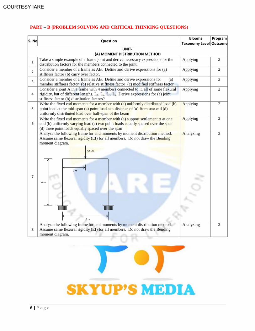
7
Analyze the following frame for end moments by moment distribution method.
Assume same flexural rigidity (EI) for all members. Do not draw the Bending
moment diagram.
Analyzing 2
8 Analyze the following frame for end moments by moment distribution method.
Assume same flexural rigidity (EI) for all members. Do not draw the Bending
moment diagram.
Analyzing 2
COURTESY IARE
7 | P a g e
S. No Question Blooms
Taxonomy Level Program Outcome
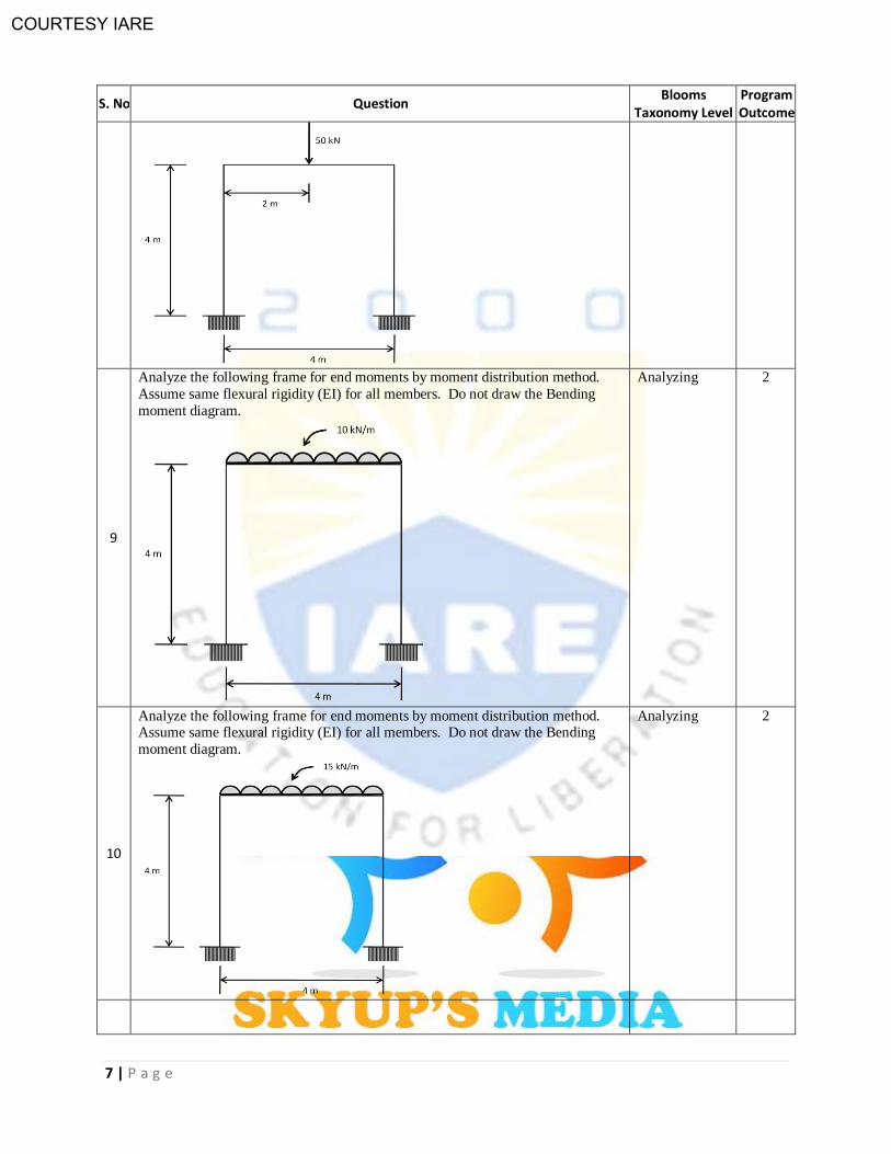
9
Analyze the following frame for end moments by moment distribution method.
Assume same flexural rigidity (EI) for all members. Do not draw the Bending
moment diagram.
Analyzing 2
10
Analyze the following frame for end moments by moment distribution method. Assume same flexural rigidity (EI) for all members. Do not draw the Bending
moment diagram.
Analyzing 2
COURTESY IARE
8 | P a g e
S. No Question Blooms
Taxonomy Level Program Outcome
(B) KANI’S METHOD
11 Write the fixed-end moments for a member with rotation at one of its supports Applying 2
12 Derive the expression for rotation factor for a member AB at joint A as used in
Kani’s method for analysis of frames Applying 2
13 Write the steps for Kani’s method of analysis of a portal frame with sway. Applying 2
14 Write and explain expressions for displacement contribution factors in Kani’s
method of analysis.
Applying 2
15 Consider a joint A in a frame with 4 members connected to it, all of same flexural
rigidity, but of different lengths, L1, L2, L3, L4. Derive expressions for rotation
factors for each member?
Applying 2
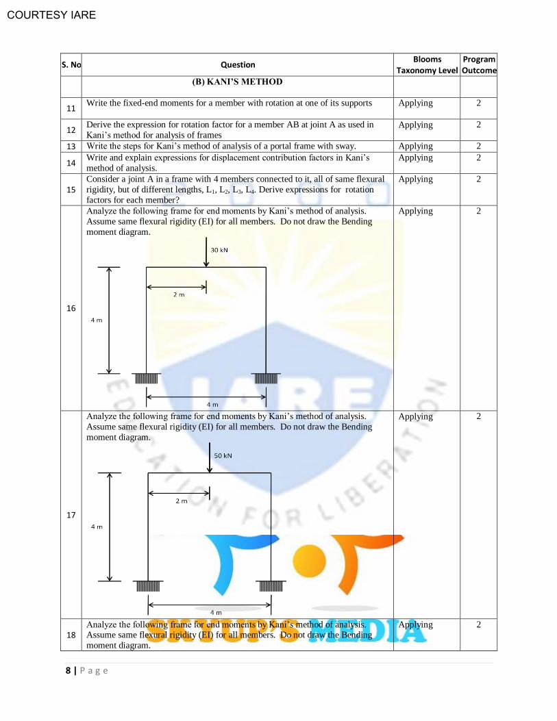
16
Analyze the following frame for end moments by Kani’s method of analysis.
Assume same flexural rigidity (EI) for all members. Do not draw the Bending
moment diagram.
Applying 2
17
Analyze the following frame for end moments by Kani’s method of analysis.
Assume same flexural rigidity (EI) for all members. Do not draw the Bending
moment diagram.
Applying 2
18 Analyze the following frame for end moments by Kani’s method of analysis. Assume same flexural rigidity (EI) for all members. Do not draw the Bending
moment diagram.
Applying 2

COURTESY IARE
9 | P a g e
S. No Question Blooms
Taxonomy Level Program Outcome
19
Analyze the following frame for end moments by Kani’s method of analysis.
Assume same flexural rigidity (EI) for all members. Do not draw the Bending
moment diagram.
Applying 2
20
Using the concept of symmetry, analyze the following frame for end moments by
Kani’s method of analysis. Assume same flexural rigidity (EI) for all members.
Do not draw the Bending moment diagram.
Applying 2
COURTESY IARE
10 | P a g e
S. No Question Blooms
Taxonomy Level Program Outcome
UNIT-II (A) SLOPE DEFLECTION METHOD
1 Explain the steps involved in Slope-Deflection method of analysis Understanding
2
2 Derive slope deflection equations of a member which includes member axis
rotation (or settlement of one support).
Applying 2
3 Derive the simplified slope-deflection equation for a member with a hinged end. Applying
2
4 Derive the shear equation in slope-deflection method for the case of a frame with
sidesway.
Applying
2
5 Explain the effects of support settlement on indeterminate structure. Applying
2
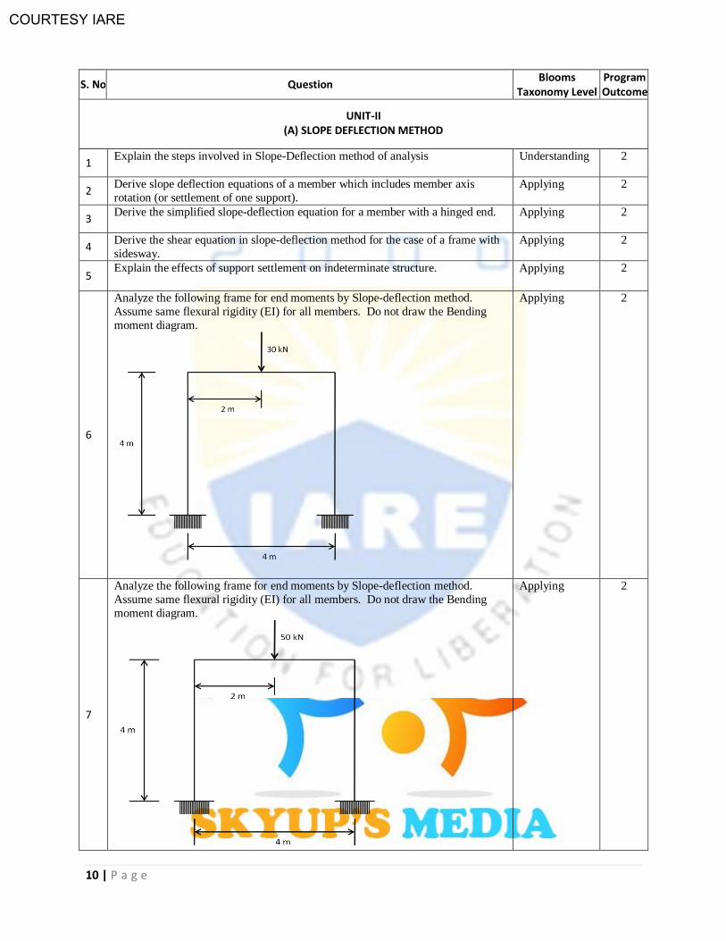
6
Analyze the following frame for end moments by Slope-deflection method.
Assume same flexural rigidity (EI) for all members. Do not draw the Bending
moment diagram.
Applying 2
7
Analyze the following frame for end moments by Slope-deflection method.
Assume same flexural rigidity (EI) for all members. Do not draw the Bending
moment diagram.
Applying
2
COURTESY IARE
11 | P a g e
S. No Question Blooms
Taxonomy Level Program Outcome
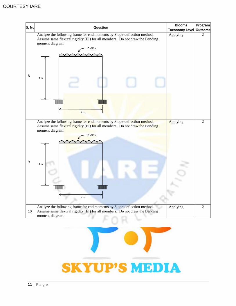
8
Analyze the following frame for end moments by Slope-deflection method.
Assume same flexural rigidity (EI) for all members. Do not draw the Bending moment diagram.
Applying
2
9
Analyze the following frame for end moments by Slope-deflection method.
Assume same flexural rigidity (EI) for all members. Do not draw the Bending
moment diagram.
Applying
2
10 Analyze the following frame for end moments by Slope-deflection method.
Assume same flexural rigidity (EI) for all members. Do not draw the Bending
moment diagram.
Applying
2
COURTESY IARE
12 | P a g e
S. No Question Blooms
Taxonomy Level Program Outcome
(B) TWO HINGED ARCHES
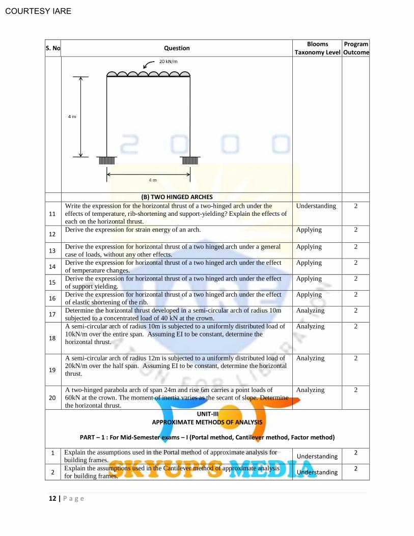
11 Write the expression for the horizontal thrust of a two-hinged arch under the
effects of temperature, rib-shortening and support-yielding? Explain the effects of
each on the horizontal thrust.
Understanding 2
12 Derive the expression for strain energy of an arch. Applying 2
13 Derive the expression for horizontal thrust of a two hinged arch under a general
case of loads, without any other effects.
Applying 2
14 Derive the expression for horizontal thrust of a two hinged arch under the effect
of temperature changes.
Applying 2
15 Derive the expression for horizontal thrust of a two hinged arch under the effect
of support yielding. Applying 2
16 Derive the expression for horizontal thrust of a two hinged arch under the effect
of elastic shortening of the rib. Applying 2
17 Determine the horizontal thrust developed in a semi-circular arch of radius 10m
subjected to a concentrated load of 40 kN at the crown. Analyzing 2
18
A semi-circular arch of radius 10m is subjected to a uniformly distributed load of
10kN/m over the entire span. Assuming EI to be constant, determine the
horizontal thrust.
Analyzing 2
19
A semi-circular arch of radius 12m is subjected to a uniformly distributed load of 20kN/m over the half span. Assuming EI to be constant, determine the horizontal
thrust.
Analyzing 2
20 A two-hinged parabola arch of span 24m and rise 6m carries a point loads of
60kN at the crown. The moment of inertia varies as the secant of slope. Determine
the horizontal thrust.
Analyzing 2
UNIT-III APPROXIMATE METHODS OF ANALYSIS
PART – 1 : For Mid-Semester exams – I (Portal method, Cantilever method, Factor method)
1 Explain the assumptions used in the Portal method of approximate analysis for
building frames. Understanding
2
2 Explain the assumptions used in the Cantilever method of approximate analysis
for building frames. Understanding
2
COURTESY IARE
13 | P a g e
S. No Question Blooms
Taxonomy Level Program Outcome
3 Explain the concept used in the Factor method of approximate analysis for
building frames. Understanding
2
4 Write the steps involved in the Portal method of approximate analysis for building frames.
Understanding 2
5 Write the steps involved in the Cantilever method of approximate analysis for
building frames. Understanding
2
6 Write the steps involved in the Factor method of approximate analysis for building
frames. Understanding
2
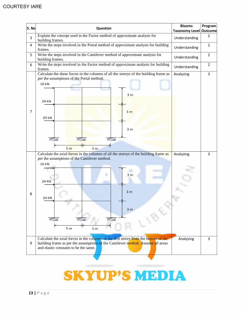
7
Calculate the shear forces in the columns of all the storeys of the building frame as
per the assumptions of the Portal method.
Analyzing 3
8
Calculate the axial forces in the columns of all the storeys of the building frame as
per the assumptions of the Cantilever method.
Analyzing 3
9 Calculate the axial forces in the columns of the first storey from the bottom of the
building frame as per the assumptions of the Cantilever method. Assume all areas
and elastic constants to be the same.
Analyzing 3
COURTESY IARE
14 | P a g e
S. No Question Blooms
Taxonomy Level Program Outcome
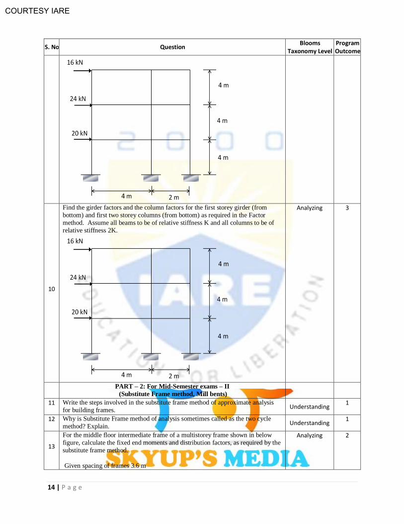
10
Find the girder factors and the column factors for the first storey girder (from
bottom) and first two storey columns (from bottom) as required in the Factor
method. Assume all beams to be of relative stiffness K and all columns to be of
relative stiffness 2K.
Analyzing 3
PART – 2: For Mid-Semester exams – II
(Substitute Frame method, Mill bents)
11 Write the steps involved in the substitute frame method of approximate analysis
for building frames. Understanding
1
12 Why is Substitute Frame method of analysis sometimes called as the two cycle
method? Explain. Understanding
1
13
For the middle floor intermediate frame of a multistorey frame shown in below
figure, calculate the fixed end moments and distribution factors, as required by the
substitute frame method.
Given spacing of frames 3.6 m
Analyzing 2
COURTESY IARE
15 | P a g e
S. No Question Blooms
Taxonomy Level Program Outcome
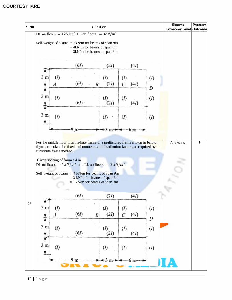
DL on floors LL on floors
Self-weight of beams = 5kN/m for beams of span 9m
= 4kN/m for beams of span 6m
= 3kN/m for beams of span 3m
14
For the middle floor intermediate frame of a multistorey frame shown in below
figure, calculate the fixed end moments and distribution factors, as required by the
substitute frame method.
Given spacing of frames 4 m
DL on floors and LL on floors
Self-weight of beams = 4 kN/m for beams of span 9m
= 3 kN/m for beams of span 6m
= 3 kN/m for beams of span 3m
Analyzing 2
COURTESY IARE
16 | P a g e
S. No Question Blooms
Taxonomy Level Program Outcome
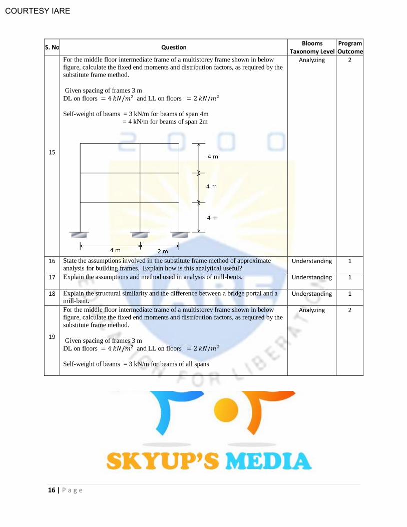
15
For the middle floor intermediate frame of a multistorey frame shown in below
figure, calculate the fixed end moments and distribution factors, as required by the substitute frame method.
Given spacing of frames 3 m
DL on floors and LL on floors
Self-weight of beams = 3 kN/m for beams of span 4m
= 4 kN/m for beams of span 2m
Analyzing 2
16 State the assumptions involved in the substitute frame method of approximate
analysis for building frames. Explain how is this analytical useful? Understanding 1
17 Explain the assumptions and method used in analysis of mill-bents. Understanding 1
18 Explain the structural similarity and the difference between a bridge portal and a mill-bent.
Understanding 1
19
For the middle floor intermediate frame of a multistorey frame shown in below
figure, calculate the fixed end moments and distribution factors, as required by the
substitute frame method.
Given spacing of frames 3 m
DL on floors and LL on floors
Self-weight of beams = 3 kN/m for beams of all spans
Analyzing 2

COURTESY IARE
17 | P a g e
S. No Question Blooms
Taxonomy Level Program Outcome
20
For the middle floor intermediate frame of a multistorey frame shown in below
figure, calculate the fixed end moments and distribution factors, as required by the
substitute frame method.
Given spacing of frames 4 m
DL on floors and LL on floors
Self-weight of beams = 4 kN/m for beams of all spans
Analyzing 2
UNIT-IV MATRIX METHODS OF ANALYSIS
1 How are the basic equations of stiffness matrix method obtained? Understanding
1
2 What is the equilibrium condition used in the stiffness method? Understanding 1
3 Write the element stiffness matrix for a truss element. What is structure/global
stiffness matrix? Understanding
1
4 Write the element stiffness matrix for a beam element. Understanding
1
5 Compare flexibility method and stiffness method. Understanding 1
6 Define flexibility influence coefficient (fij). Remembering 1
7 Write the element flexibility matrix (f) for a truss member & for a beam element Applying 2
COURTESY IARE
18 | P a g e
S. No Question Blooms
Taxonomy Level Program Outcome
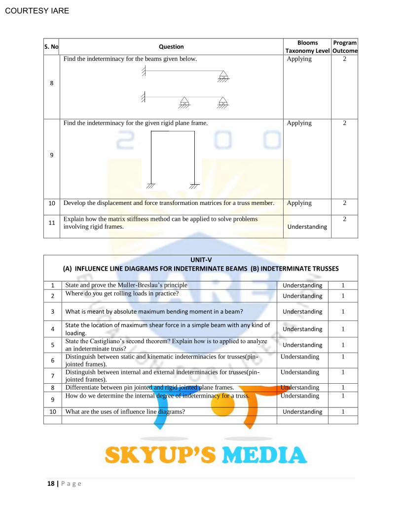
8
Find the indeterminacy for the beams given below.
Applying 2
9
Find the indeterminacy for the given rigid plane frame.
Applying 2
10 Develop the displacement and force transformation matrices for a truss member. Applying 2
11 Explain how the matrix stiffness method can be applied to solve problems
involving rigid frames.
Understanding
2
UNIT-V (A) INFLUENCE LINE DIAGRAMS FOR INDETERMINATE BEAMS (B) INDETERMINATE TRUSSES
1 State and prove the Muller-Breslau’s principle Understanding 1
2 Where do you get rolling loads in practice? Understanding 1
3 What is meant by absolute maximum bending moment in a beam? Understanding 1
4 State the location of maximum shear force in a simple beam with any kind of loading.
Understanding 1
5 State the Castigliano’s second theorem? Explain how is to applied to analyze
an indeterminate truss? Understanding 1
6 Distinguish between static and kinematic indeterminacies for trusses(pin-
jointed frames).
Understanding 1
7 Distinguish between internal and external indeterminacies for trusses(pin-jointed frames).
Understanding 1
8 Differentiate between pin jointed and rigid jointed plane frames. Understanding 1
9 How do we determine the internal degree of indeterminacy for a truss. Understanding 1
10 What are the uses of influence line diagrams? Understanding 1
COURTESY IARE
19 | P a g e
PART – C (ANALYTICAL QUESTIONS)
S.No QUESTIONS Blooms Taxonomy
Level Program Outcome
UNIT-I MOMENT DISTRIBUTION METHOD AND KANI’S METHOD
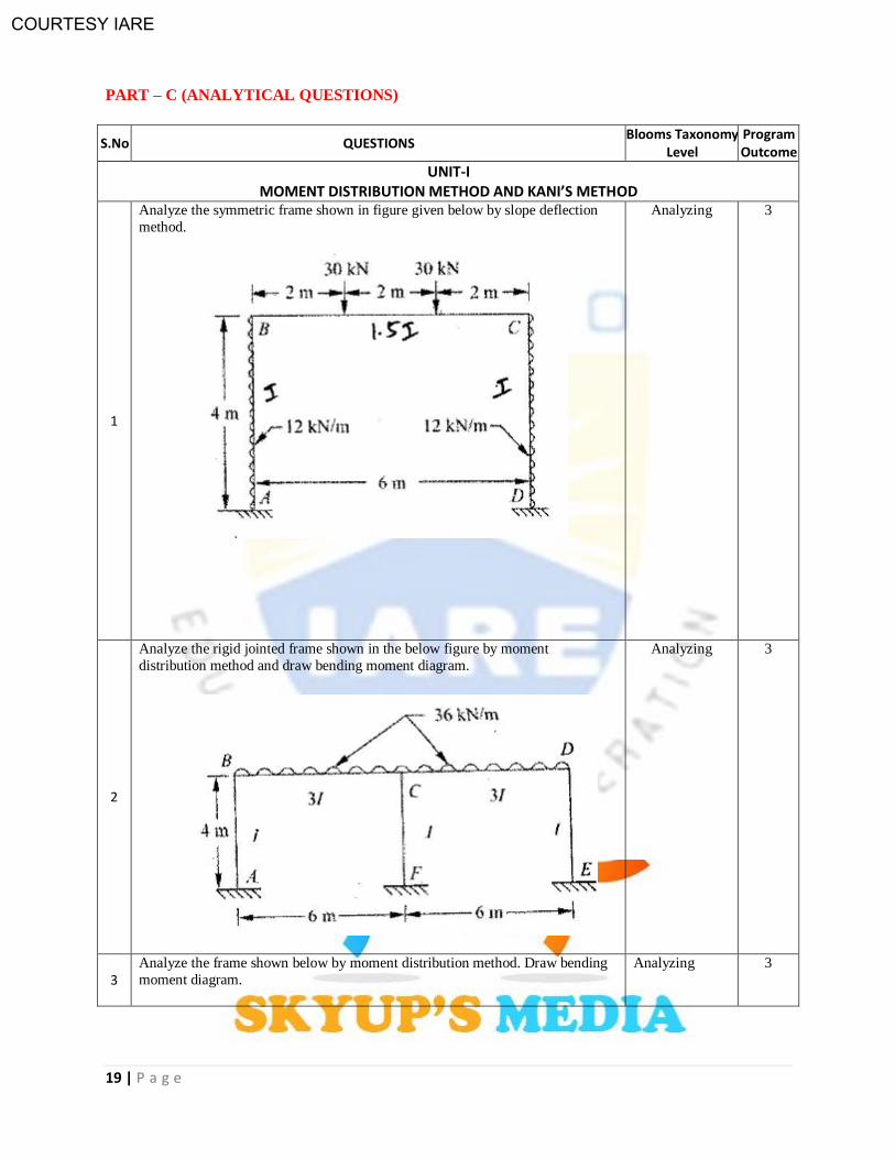
1
Analyze the symmetric frame shown in figure given below by slope deflection
method.
Analyzing 3
2
Analyze the rigid jointed frame shown in the below figure by moment
distribution method and draw bending moment diagram.
Analyzing
3
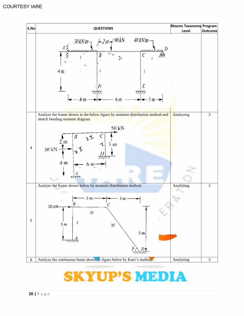
3 Analyze the frame shown below by moment distribution method. Draw bending
moment diagram.
Analyzing
3
COURTESY IARE
20 | P a g e
S.No QUESTIONS Blooms Taxonomy
Level Program Outcome
4
Analyze the frame shown in the below figure by moment distribution method and sketch bending moment diagram.
Analyzing
3
5
Analyze the frame shown below by moment distribution method.
Analyzing 3
6 Analyze the continuous beam shown in figure below by Kani’s method. Analyzing 3
COURTESY IARE
21 | P a g e
S.No QUESTIONS Blooms Taxonomy
Level Program Outcome
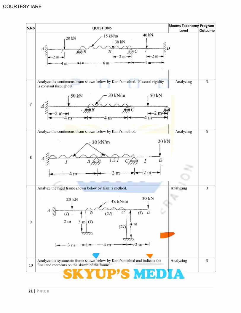
7
Analyze the continuous beam shown below by Kani’s method. Flexural rigidity
is constant throughout.
Analyzing 3
8
Analyze the continuous beam shown below by Kani’s method.
Analyzing
5
9
Analyze the rigid frame shown below by Kani’s method.
Analyzing 3
10 Analyze the symmetric frame shown below by Kani’s method and indicate the final end moments on the sketch of the frame.
Analyzing 3
COURTESY IARE
22 | P a g e
S.No QUESTIONS Blooms Taxonomy
Level Program Outcome
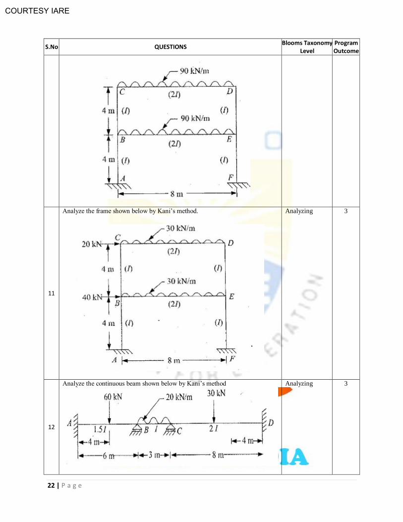
11
Analyze the frame shown below by Kani’s method.
Analyzing 3
12
Analyze the continuous beam shown below by Kani’s method
Analyzing 3
COURTESY IARE
23 | P a g e
S.No QUESTIONS Blooms Taxonomy
Level Program Outcome
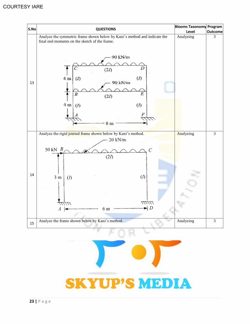
13
Analyze the symmetric frame shown below by Kani’s method and indicate the
final end moments on the sketch of the frame.
Analyzing 3
14
Analyze the rigid jointed frame shown below by Kani’s method.
Analyzing 3
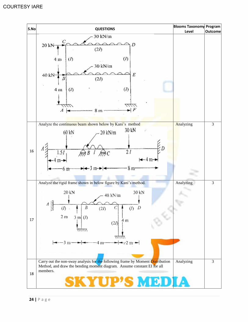
15 Analyze the frame shown below by Kani’s method. Analyzing 3
COURTESY IARE
24 | P a g e
S.No QUESTIONS Blooms Taxonomy
Level Program Outcome
16
Analyze the continuous beam shown below by Kani’s method
Analyzing 3
17
Analyze the rigid frame shown in below figure by Kani’s method.
Analyzing 3
18
Carry out the non-sway analysis for the following frame by Moment Distribution
Method, and draw the bending moment diagram. Assume constant EI for all
members.
Analyzing 3

COURTESY IARE
25 | P a g e
S.No QUESTIONS Blooms Taxonomy
Level Program Outcome
19
Carry out the sway analysis for the following frame by Moment Distribution Method, and draw the bending moment diagram. Assume constant EI for all
members.
Analyzing 3
20 Analyze the following frame by Moment Distribution Method, and draw the
bending moment diagram. Assume constant EI for all members.
Analyzing 3

COURTESY IARE
26 | P a g e
S.No QUESTIONS Blooms Taxonomy
Level Program Outcome
UNIT-II (A) SLOPE DEFLECTION METHOD (B) TWO-HINGED ARCHES
1
Analyze the frame shown below by slope deflection method and draw bending
moment diagram.
Analyzing 3
COURTESY IARE
27 | P a g e
S.No QUESTIONS Blooms Taxonomy
Level Program Outcome
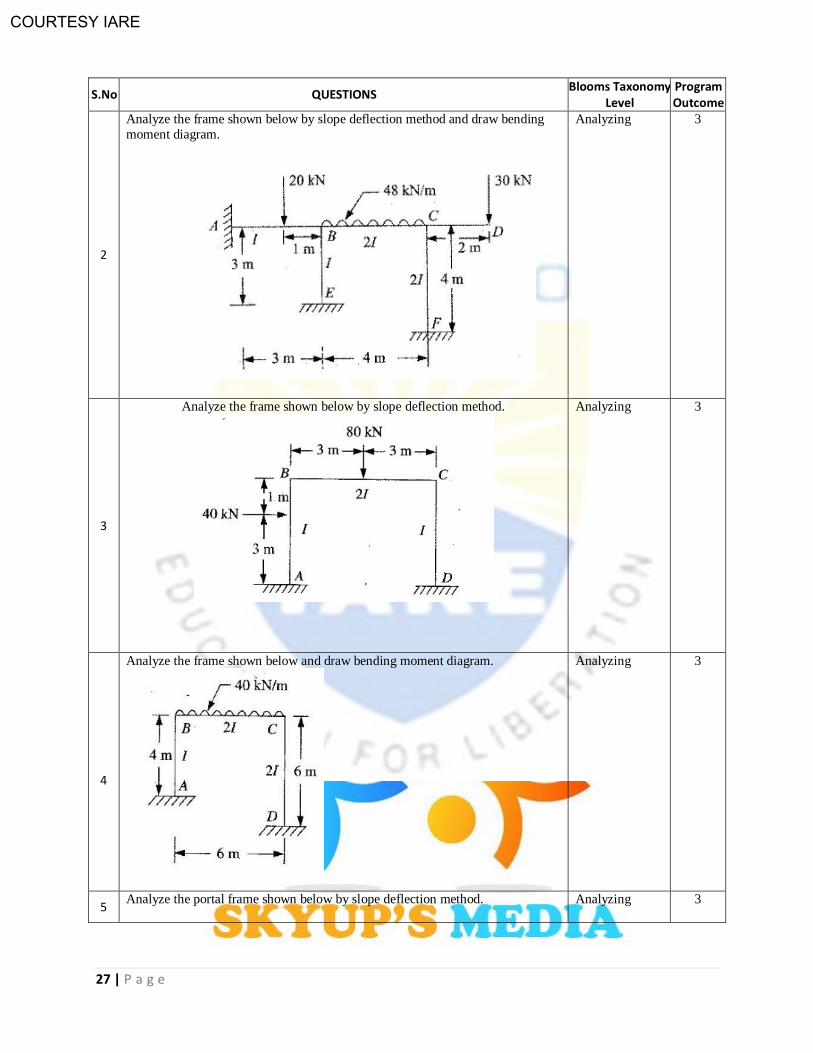
2
Analyze the frame shown below by slope deflection method and draw bending
moment diagram.
Analyzing 3
3
Analyze the frame shown below by slope deflection method.
Analyzing 3
4
Analyze the frame shown below and draw bending moment diagram.
Analyzing 3
5 Analyze the portal frame shown below by slope deflection method. Analyzing 3
COURTESY IARE
28 | P a g e
S.No QUESTIONS Blooms Taxonomy
Level Program Outcome
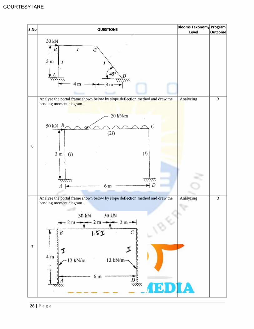
6
Analyze the portal frame shown below by slope deflection method and draw the
bending moment diagram.
Analyzing 3
7
Analyze the portal frame shown below by slope deflection method and draw the
bending moment diagram.
Analyzing 3
COURTESY IARE
29 | P a g e
S.No QUESTIONS Blooms Taxonomy
Level Program Outcome
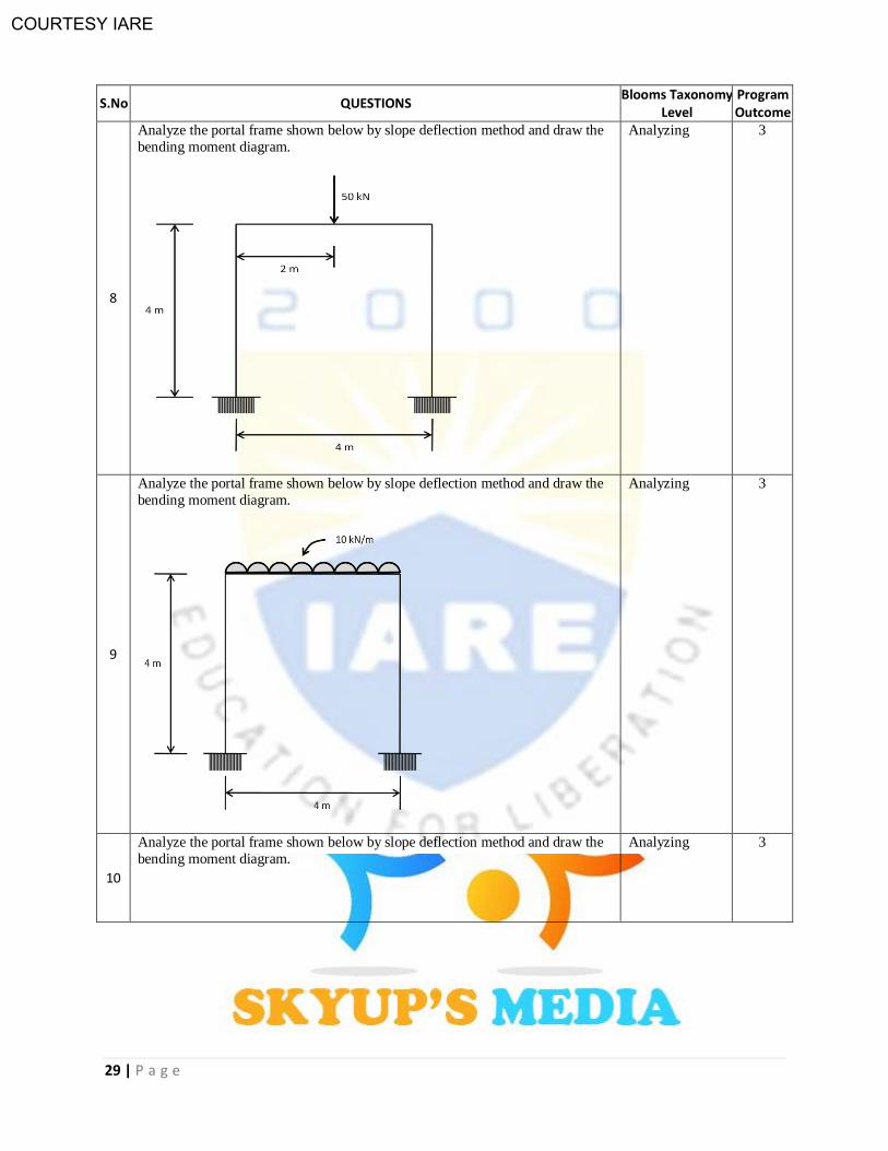
8
Analyze the portal frame shown below by slope deflection method and draw the
bending moment diagram.
Analyzing 3
9
Analyze the portal frame shown below by slope deflection method and draw the
bending moment diagram.
Analyzing 3
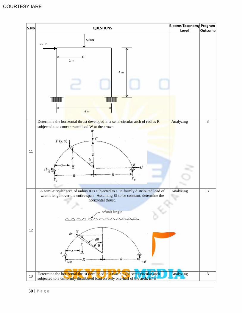
10
Analyze the portal frame shown below by slope deflection method and draw the
bending moment diagram.
Analyzing 3
COURTESY IARE
30 | P a g e
S.No QUESTIONS Blooms Taxonomy
Level Program Outcome
11
Determine the horizontal thrust developed in a semi-circular arch of radius R
subjected to a concentrated load W at the crown.
Analyzing 3
12
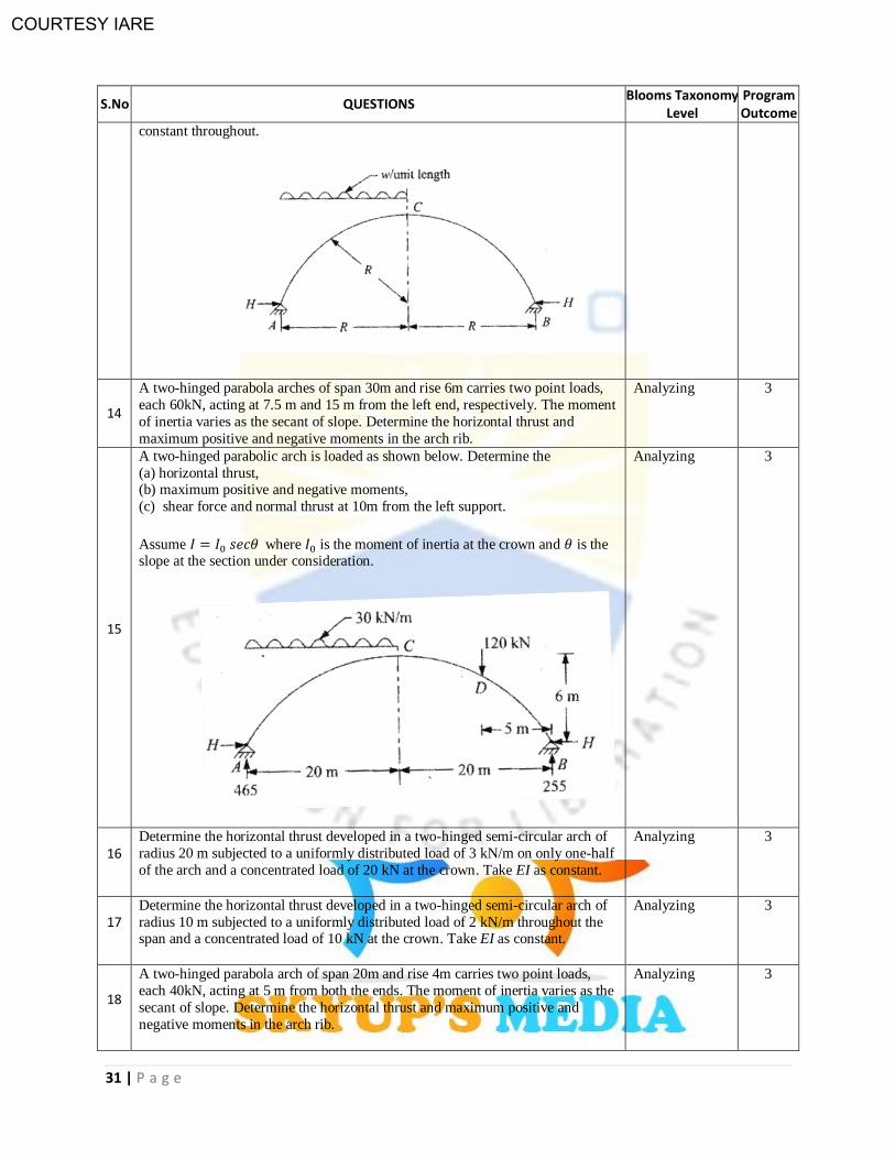
A semi-circular arch of radius R is subjected to a uniformly distributed load of
w/unit length over the entire span. Assuming EI to be constant, determine the
horizontal thrust.
Analyzing 3
13 Determine the horizontal thrust developed in a two-hinged semi-circular arch
subjected to a uniformly distributed load on only one-half of the arch. EI is
Analyzing 3
COURTESY IARE
31 | P a g e
S.No QUESTIONS Blooms Taxonomy
Level Program Outcome
constant throughout.
14
A two-hinged parabola arches of span 30m and rise 6m carries two point loads,
each 60kN, acting at 7.5 m and 15 m from the left end, respectively. The moment
of inertia varies as the secant of slope. Determine the horizontal thrust and
maximum positive and negative moments in the arch rib.
Analyzing 3
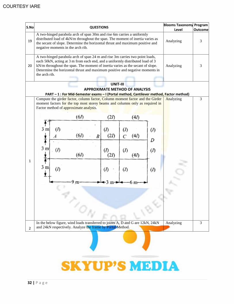
15
A two-hinged parabolic arch is loaded as shown below. Determine the
(a) horizontal thrust, (b) maximum positive and negative moments,
(c) shear force and normal thrust at 10m from the left support.
Assume where is the moment of inertia at the crown and is the slope at the section under consideration.
Analyzing 3
16 Determine the horizontal thrust developed in a two-hinged semi-circular arch of
radius 20 m subjected to a uniformly distributed load of 3 kN/m on only one-half
of the arch and a concentrated load of 20 kN at the crown. Take EI as constant.
Analyzing 3
17 Determine the horizontal thrust developed in a two-hinged semi-circular arch of
radius 10 m subjected to a uniformly distributed load of 2 kN/m throughout the span and a concentrated load of 10 kN at the crown. Take EI as constant.
Analyzing 3
18
A two-hinged parabola arch of span 20m and rise 4m carries two point loads,
each 40kN, acting at 5 m from both the ends. The moment of inertia varies as the
secant of slope. Determine the horizontal thrust and maximum positive and
negative moments in the arch rib.
Analyzing 3
COURTESY IARE
32 | P a g e
S.No QUESTIONS Blooms Taxonomy
Level Program Outcome
19
A two-hinged parabola arch of span 30m and rise 6m carries a uniformly
distributed load of 4kN/m throughout the span. The moment of inertia varies as the secant of slope. Determine the horizontal thrust and maximum positive and
negative moments in the arch rib.
Analyzing 3
20
A two-hinged parabola arch of span 24 m and rise 3m carries two point loads,
each 50kN, acting at 3 m from each end, and a uniformly distributed load of 3
kN/m throughout the span. The moment of inertia varies as the secant of slope.
Determine the horizontal thrust and maximum positive and negative moments in
the arch rib.
Analyzing 3
UNIT-III APPROXIMATE METHOD OF ANALYSIS
PART – 1 : For Mid-Semester exams – I (Portal method, Cantilever method, Factor method)
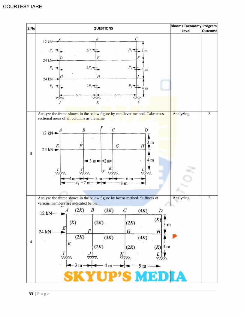
1
Compute the girder factor, column factor, Column moment factor and the Girder
moment factors for the top most storey beams and columns only as required in
Factor method of approximate analysis.
Analyzing
3
2
In the below figure, wind loads transferred to joints A, D and G are 12kN, 24kN and 24kN respectively. Analyze the frame by Portal Method.
Analyzing 3
COURTESY IARE
33 | P a g e
S.No QUESTIONS Blooms Taxonomy
Level Program Outcome
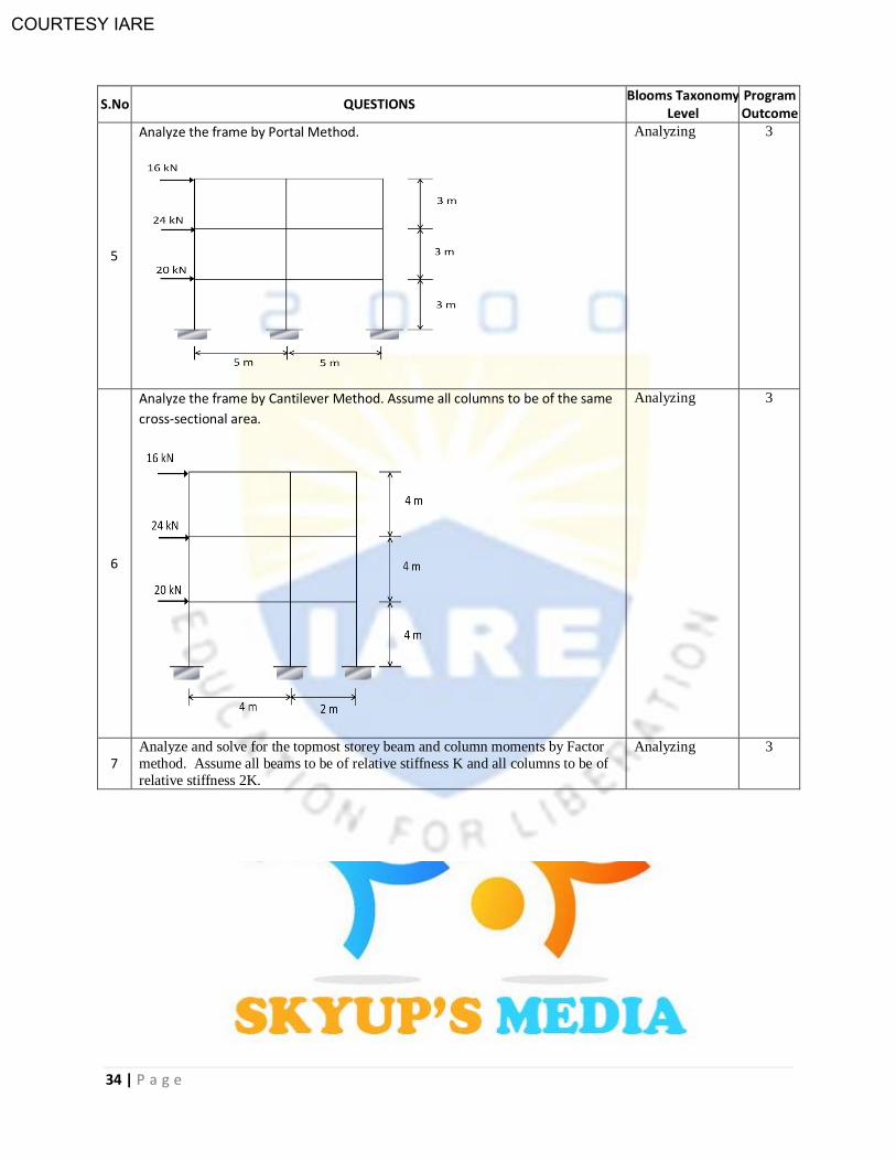
3
Analyze the frame shown in the below figure by cantilever method. Take cross-
sectional areas of all columns as the same.
Analyzing
3
4
Analyze the frame shown in the below figure by factor method. Stiffness of
various members are indicated below.
Analyzing
3
COURTESY IARE
34 | P a g e
S.No QUESTIONS Blooms Taxonomy
Level Program Outcome
5
Analyze the frame by Portal Method.
Analyzing 3
6
Analyze the frame by Cantilever Method. Assume all columns to be of the same
cross-sectional area.
Analyzing 3
7 Analyze and solve for the topmost storey beam and column moments by Factor
method. Assume all beams to be of relative stiffness K and all columns to be of
relative stiffness 2K.
Analyzing 3

COURTESY IARE
35 | P a g e
S.No QUESTIONS Blooms Taxonomy
Level Program Outcome
8
Analyze the frame by Cantilever Method.
Analyzing 3
9
Analyze the frame by Portal Method.
Analyzing 3
10 Analyze the frame by Factor method. Assume stiffness of all members to be
equal.
Analyzing 3
COURTESY IARE
36 | P a g e
S.No QUESTIONS Blooms Taxonomy
Level Program Outcome
APPROXIMATE METHOD OF ANALYSIS
PART – 2 : For Mid-Semester exams – I (Substitute Frame Method, Mill bents)
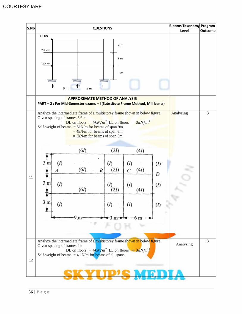
11
Analyze the intermediate frame of a multistorey frame shown in below figure.
Given spacing of frames 3.6 m
DL on floors LL on floors Self-weight of beams = 5kN/m for beams of span 9m
= 4kN/m for beams of span 6m
= 3kN/m for beams of span 3m
Analyzing
3
12
Analyze the intermediate frame of a multistorey frame shown in below figure.
Given spacing of frames 4 m
DL on floors LL on floors
Self-weight of beams = 4 kN/m for beams of all spans
Analyzing 3
COURTESY IARE
37 | P a g e
S.No QUESTIONS Blooms Taxonomy
Level Program Outcome
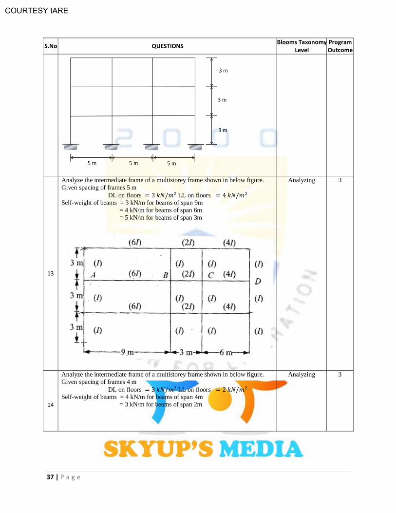
13
Analyze the intermediate frame of a multistorey frame shown in below figure.
Given spacing of frames 5 m
DL on floors LL on floors Self-weight of beams = 3 kN/m for beams of span 9m
= 4 kN/m for beams of span 6m
= 5 kN/m for beams of span 3m
Analyzing
3
14
Analyze the intermediate frame of a multistorey frame shown in below figure.
Given spacing of frames 4 m
DL on floors LL on floors Self-weight of beams = 4 kN/m for beams of span 4m
= 3 kN/m for beams of span 2m
Analyzing
3
COURTESY IARE
38 | P a g e
S.No QUESTIONS Blooms Taxonomy
Level Program Outcome
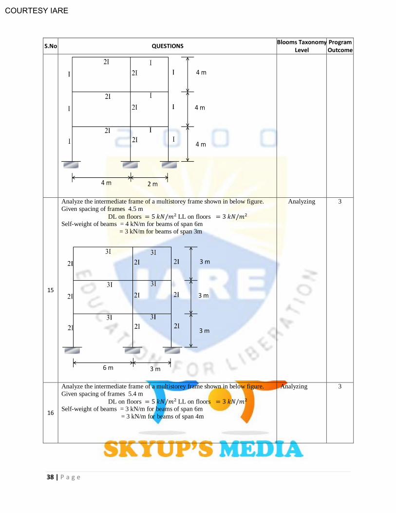
15
Analyze the intermediate frame of a multistorey frame shown in below figure.
Given spacing of frames 4.5 m
DL on floors LL on floors Self-weight of beams = 4 kN/m for beams of span 6m
= 3 kN/m for beams of span 3m
Analyzing
3
16
Analyze the intermediate frame of a multistorey frame shown in below figure.
Given spacing of frames 5.4 m
DL on floors LL on floors Self-weight of beams = 3 kN/m for beams of span 6m
= 3 kN/m for beams of span 4m
Analyzing
3
COURTESY IARE
39 | P a g e
S.No QUESTIONS Blooms Taxonomy
Level Program Outcome
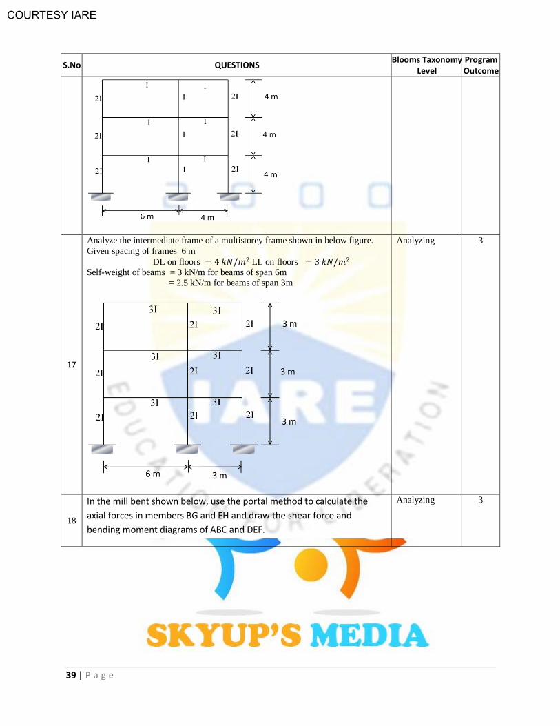
17
Analyze the intermediate frame of a multistorey frame shown in below figure.
Given spacing of frames 6 m
DL on floors LL on floors Self-weight of beams = 3 kN/m for beams of span 6m
= 2.5 kN/m for beams of span 3m
Analyzing 3
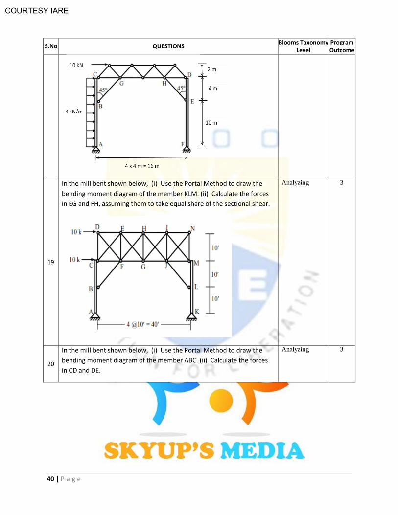
18
In the mill bent shown below, use the portal method to calculate the
axial forces in members BG and EH and draw the shear force and
bending moment diagrams of ABC and DEF.
Analyzing 3
COURTESY IARE
40 | P a g e
S.No QUESTIONS Blooms Taxonomy
Level Program Outcome
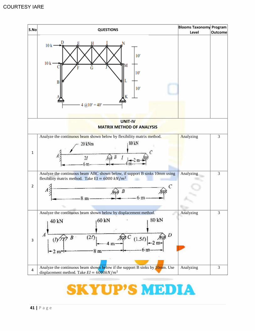
19
In the mill bent shown below, (i) Use the Portal Method to draw the
bending moment diagram of the member KLM. (ii) Calculate the forces
in EG and FH, assuming them to take equal share of the sectional shear.
Analyzing 3
20
In the mill bent shown below, (i) Use the Portal Method to draw the
bending moment diagram of the member ABC. (ii) Calculate the forces
in CD and DE.
Analyzing 3
COURTESY IARE
41 | P a g e
S.No QUESTIONS Blooms Taxonomy
Level Program Outcome
UNIT-IV MATRIX METHOD OF ANALYSIS
1
Analyze the continuous beam shown below by flexibility matrix method.
Analyzing 3
2
Analyze the continuous beam ABC shown below, if support B sinks 10mm using
flexibility matrix method. Take EI
Analyzing 3
3
Analyze the continuous beam shown below by displacement method.
Analyzing 3
4 Analyze the continuous beam shown below if the support B sinks by 10mm. Use
displacement method. Take EI
Analyzing
3
COURTESY IARE
42 | P a g e
S.No QUESTIONS Blooms Taxonomy
Level Program Outcome
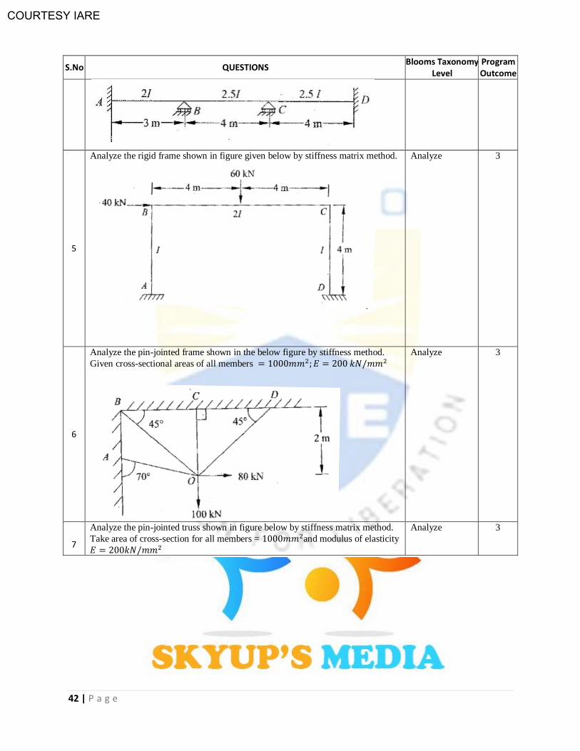
5
Analyze the rigid frame shown in figure given below by stiffness matrix method.
Analyze 3
6
Analyze the pin-jointed frame shown in the below figure by stiffness method.
Given cross-sectional areas of all members
Analyze 3
7
Analyze the pin-jointed truss shown in figure below by stiffness matrix method.
Take area of cross-section for all members = and modulus of elasticity
Analyze
3
COURTESY IARE
43 | P a g e
S.No QUESTIONS Blooms Taxonomy
Level Program Outcome
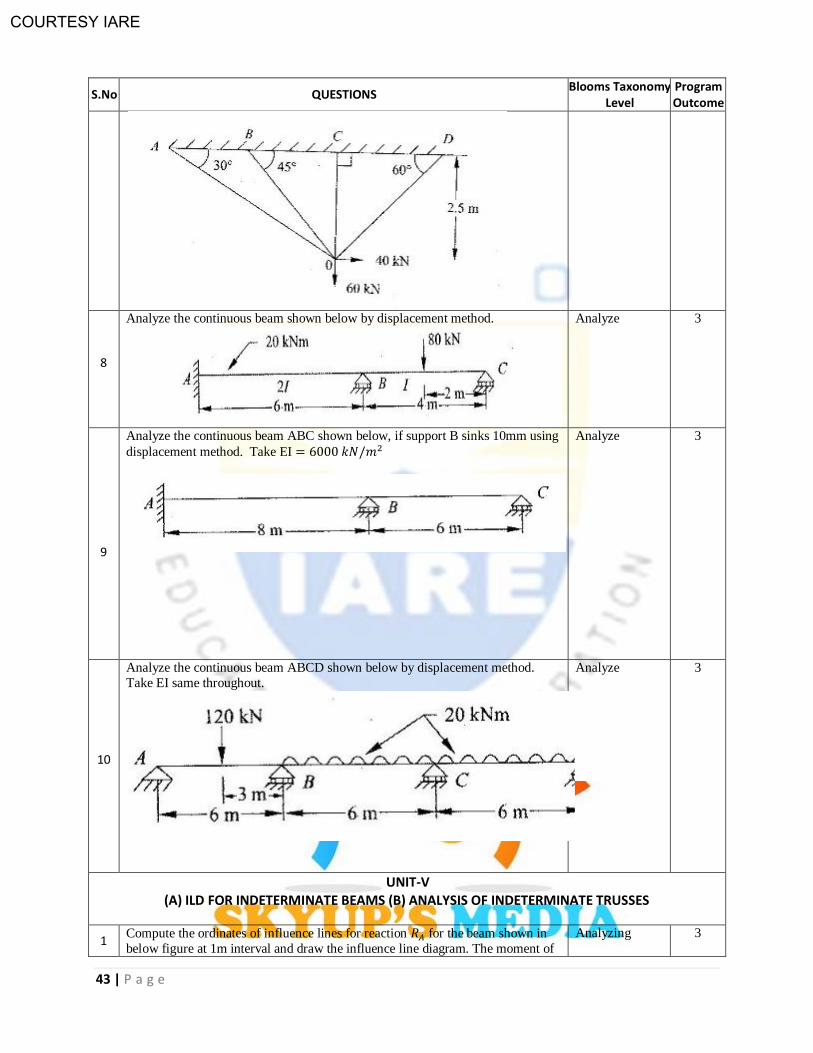
8
Analyze the continuous beam shown below by displacement method.
Analyze 3
9
Analyze the continuous beam ABC shown below, if support B sinks 10mm using
displacement method. Take EI
Analyze 3
10
Analyze the continuous beam ABCD shown below by displacement method.
Take EI same throughout.
Analyze 3
UNIT-V (A) ILD FOR INDETERMINATE BEAMS (B) ANALYSIS OF INDETERMINATE TRUSSES
1 Compute the ordinates of influence lines for reaction for the beam shown in
below figure at 1m interval and draw the influence line diagram. The moment of
Analyzing
3
COURTESY IARE
44 | P a g e
S.No QUESTIONS Blooms Taxonomy
Level Program Outcome
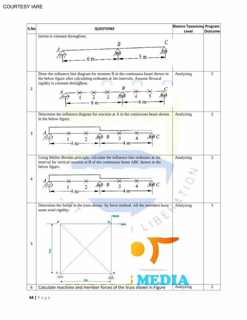
inertia is constant throughout.
2
Draw the influence line diagram for moment B in the continuous beam shown in
the below figure after calculating ordinates at 2m intervals. Assume flexural
rigidity is constant throughout.
Analyzing
3
3
Determine the influence diagram for reaction at A in the continuous beam shown
in the below figure.
Analyzing
3
4
Using Muller-Breslau principle, calculate the influence line ordinates at 2m
interval for vertical reaction at B of the continuous beam ABC shown in the below figure.
Analyzing
3
5
Determine the forces in the truss shown by force method. All the members have
same axial rigidity.
Analyzing
3
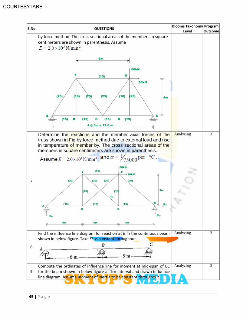
6 Calculate reactions and member forces of the truss shown in Figure Analyzing 3
COURTESY IARE
45 | P a g e
S.No QUESTIONS Blooms Taxonomy
Level Program Outcome
by force method. The cross sectional areas of the members in square centimeters are shown in parenthesis. Assume
.
7
Determine the reactions and the member axial forces of the truss shown in Fig by force method due to external load and rise in temperature of member by. The cross sectional areas of the members in square centimeters are shown in parenthesis.
Analyzing 3
8
Find the influence line diagram for reaction at B in the continuous beam shown in below figure. Take El as constant throughout.
Analyzing 3
9
Compute the ordinates of influence line for moment at mid-span of BC for the beam shown in below figure at 1rn interval and drawn influence line diagram. Assume moment of inertia to be constant throughout.
Analyzing 3

COURTESY IARE
46 | P a g e
S.No QUESTIONS Blooms Taxonomy
Level Program Outcome
10
Draw the influence line diagram for shear force at D in the beam shown in below figure after computing the values of the ordinates at 1m interval.
Analyzing 3
Prepared By: Akshay S. K. Naidu