Embed Size (px)
Citation preview
Institute for Computational Mathematics Hong Kong Baptist University
ICM Research Report 11-02
High Order Weighted Essentially Non-Oscillation Schemes for
One-Dimensional Detonation Wave Simulations
Zhen Gao ∗, Zhiqiu Li †, Wai Sun Don ‡
January 25, 2011
Abstract
In this paper, three versions of WENO schemes WENO-JS (JCP 126, 1996), WENO-M(JCP 207, 2005) and WENO-Z (JCP 227, 2008) are used for one-dimensional detonation wavesimulations with fifth order characteristic based spatial flux reconstruction. Numerical schemesfor solving the system of hyperbolic conversation laws using the ZND analytical solution asinitial condition are presented. Numerical simulations of one-dimensional detonation wave forboth stable and unstable cases are performed. In the stable case with overdrive factor f = 1.8,the temporal histories of peak pressure of the detonation front computed by WENO-JS andWENO-Z reach the theoretical steady state. In comparison, the temporal history of peakpressure computed by the WENO-M scheme fails to reach and oscillates around the theoreticalsteady state. In the unstable cases with overdrive factors f = 1.6, f = 1.4, f = 1.34 and f = 1.3,the results of all WENO schemes agree well with each other as the resolution, defined as thenumber of grid points per half-length of reaction zone, increases. Furthermore, for overdrivefactor f = 1.6, the grid convergence study demonstrates that the high order WENO schemesconverge faster than other existing lower order schemes such as unsplit scheme, Roe’s solver withminmod limiter and Roe’s solver with superbee limiter in reaching the predicted peak pressure.For overdrive factor f = 1.3, the temporal history of peak pressure shows an increasingly chaoticbehavior even at high resolution. In the case of overdrive factor f = 1.1, in accordance withtheoretical studies, an explosion occurs and different WENO schemes leading to this explosionappear at slightly different times.
Keywords
Weighted Essentially Non-Oscillatory, Detonation, ZND
AMS
65P30, 77Axx
∗School of Mathematical Sciences, Ocean University of China, Qingdao, China. E-Mail: [email protected]†Department of Mathematics, Hong Kong Baptist University, Hong Kong, China. E-Mail: [email protected]‡Correspondence author: Department of Mathematics, Hong Kong Baptist University, Hong Kong, China. E-Mail:
1
1 Introduction
Detonation is a complex phenomenon that involves a shock front followed by a reaction zone. Theclassical theory in detonation waves was pioneered by Zekdivich [1], von Neumann [2] and Doering[3], namely the ZND detonation model. Furthermore, linear stability analysis [4] presented rigorousresults, but it is unable to capture properties of non-linear dynamics. In the 1970s, experiments[5, 6, 7] demonstrated that the detonations observed in many circumstances exhibited complicatedunstable wave patterns in reacting gases. Then both theoretical studies and numerical techniqueshave been developed to investigate the detonation phenomenon in many physical applications.Numerical approaches such as PPM with front tracking and mesh refinement [8], Roe’s solver withsuperbee limiter and the minmod limiter [9], unsplit scheme [10], and WENO-M with shock fitting[11] have been implemented to simulate detonation waves to study its instability and mechanisms.
Although detonation has been studied for many years, it remains an active area of research in boththeoretical studies and in numerical simulations due to the practical importance. In this paper,we are interested in the numerical simulations of one-dimensional detonation waves by WeightedEssentially Non-Oscillation (WENO) schemes, which have been developed in recent years as a classof high order/high resolution method for solutions of hyperbolic conservation laws in the presenceof shocks and small scale structures in the solution. It is because the global order of the scheme isof first order only while maintain high resolution in the presence of discontinuities/shock. In thisstudy, the terms high order and high resolution will be used interchangeably in the present context.
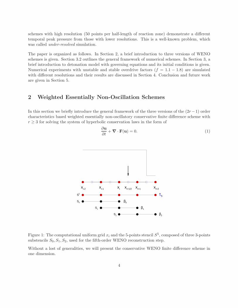
WENO schemes owe their success to the use of a dynamic set of substencils where a nonlinear convexcombination of lower order polynomials adapts either to a higher order polynomial approximationat smooth parts of the solution, or to a lower order polynomial approximation that avoids inter-polation across discontinuities (see Fig. 1). The upwinding of the spatial discretization providesthe necessary dissipation for shock capturing. It is an evolution of the Essentially Non-Oscillatory(ENO) schemes, introduced in [12], which choose only the smoothest substencil, instead of forminga convex combination of all the substencils available in order to optimize accuracy in the smoothparts of the solution.
The local computational stencils of (2r − 1) order WENO schemes are composed of r overlappingsubstencils of r points, forming a larger stencil with (2r − 1) points. The scheme yields a localrate of convergence that goes from order r at the non-smooth parts of the solution, to order(2r − 1) when the convex combination of local lower order polynomials is applied at smooth partsof the solution. The nonlinear coefficients of WENO’s convex combination, hereafter referred to asnonlinear weights, are based on lower order local smoothness indicators βk, k = 0, . . . , r − 1 thatmeasure the sum of the normalized squares of the scaled L2 norms of all derivatives of r localinterpolating polynomials. An essentially zero weight is assigned to those lower order polynomialswhose underlining substencils contain high gradients and/or shocks, aiming at an essentially non-oscillatory solution close to discontinuities. At smooth parts of the solution, higher order is achievedthrough the mimicking of the central upwind scheme of maximum order, when all smoothness
2
indicators are about the same size. Hence, an efficient and careful design of the nonlinear weightsis a delicate and important issue for WENO schemes. In this study, the fifth order (r = 3) WENOscheme will be used.
In this study of detonation wave simulations, we consider the following three favors of WENOschemes.
• In [13], the first set of nonlinear weights of widespread use has been given, hereafter denotedas ωk and the resulting scheme will be hereafter referred as the classical WENO scheme(WENO-JS).
• In [14], it was pointed out that the nonlinear weights of the classical WENO-JS scheme werethe cause of a reduction of the convergence rate at critical points (points of zero of first orhigher derivatives) of the function in the smooth stencil. A modification of the nonlinearweights was proposed in the form of a mapping on the classical WENO-JS nonlinear weights,leading to corrected nonlinear weights that recovered the formal order of accuracy at criticalpoints. We call the scheme composed by this mapped set of nonlinear weights as the mappedWENO scheme (WENO-M).
• In [15], it was shown that the incorporation of a global higher order smoothness indicator,which is denoted as τ2r−1, into the classical WENO-JS nonlinear weights definition improvedthe convergence at critical points with no need of mapping. This scheme has been named theWENO-Z scheme (WENO-Z).
It has been shown that the new set of nonlinear weights of WENO-Z provided less dissipation thanWENO-JS and yielded comparable resolution of smooth solution and captured sharp gradients withWENO-M. It should also be noted that, however, the mapping procedure of WENO-M incurs extraexpensive computational cost, while the WENO-Z modifications are obtained through a simple andinexpensive linear combination of the already computed lower order local smoothness indicatorsβk.
Numerical experiments showed that detonation waves for overdrive factor f , which is the squareof the ratio of imposed detonation front velocity and the Chapman-Jouguet velocity, f = 1.8 isa stable case and lower overdrive factors f = 1.6, f = 1.4, f = 1.34, f = 1.3 and f = 1.1 areunstable cases. For the stable case, the temporal histories of peak pressure of the detonation frontcomputed by WENO-JS and WENO-Z schemes reach the steady state while the temporal historyof peak pressure computed by the WENO-M fails to reach the steady state. For the unstablecases, the results of three versions of WENO schemes agree well with each other as resolution,defined as number of grid points per half-length of reaction zone, increases, except for overdrivefactor f = 1.3 where the temporal history of peak pressure behaves slightly different. In the caseof overdrive factor f = 1.1, which is a highly unstable case, WENO-JS, WENO-M and WENO-Zwith low resolution (15 points per half-length of reaction zone) demonstrate that the explosive riseof the peak pressure occurs at time t ≈ 75, t ≈ 70, t ≈ 66 respectively. In contrast, three WENO
3
schemes with high resolution (50 points per half-length of reaction zone) demonstrate a differenttemporal peak pressure from those with lower resolutions. This is a well-known problem, whichwas called under-resolved simulation.
The paper is organized as follows. In Section 2, a brief introduction to three versions of WENOschemes is given. Section 3.2 outlines the general framework of numerical schemes. In Section 3, abrief introduction to detonation model with governing equations and its initial conditions is given.Numerical experiments with unstable and stable overdrive factors (f = 1.1 − 1.8) are simulatedwith different resolutions and their results are discussed in Section 4. Conclusion and future workare given in Section 5.
2 Weighted Essentially Non-Oscillation Schemes
In this section we briefly introduce the general framework of the three versions of the (2r−1) ordercharacteristics based weighted essentially non-oscillatory conservative finite difference scheme withr ≥ 3 for solving the system of hyperbolic conservation laws in the form of
∂u
∂t+ ∇ ·F(u) = 0. (1)
xi xi+1 xi+2xi-1xi-2 xi+1/2
S2
S0
S1
S5 τ5
β0
β2
β1
Figure 1: The computational uniform grid xi and the 5-points stencil S5, composed of three 3-pointssubstencils S0, S1, S2, used for the fifth-order WENO reconstruction step.
Without a lost of generalities, we will present the conservative WENO finite difference scheme inone dimension.
4
Consider a uniform grid defined by the points xi = i∆x, i = 0, . . . ,N , which are called cell centers,with cell boundaries or intercell boundaries given by xi+ 1
2
= xi +∆x2 , where ∆x is the uniform grid
spacing. The semi-discretized form of (1) is transformed into the system of ordinary differentialequations by method of line
dui(t)
dt= −
∂f
∂x
∣
∣
∣
∣
x=xi
, i = 0, . . . ,N, (2)
where ui(t) is a numerical approximation to the point value u(xi, t).
To form the flux differences across the uniformly spaced cells, conservative finite-difference for-mulation for hyperbolic conservation laws requires high-order consistent numerical fluxes at thecell boundaries. The conservative property of the spatial discretization is obtained by implicitlydefining the numerical flux function h(x) as
f(x) =1
∆x
∫ x+∆x2
x−∆x2
h(ξ)dξ,
such that the spatial derivative in (2) is exactly approximated by a conservative finite differenceformula at the intercell boundaries xi± 1
2
,
dui(t)
dt=
1
∆x
(
hi+ 12
− hi− 12
)
, (3)
where hi± 12
= h(xi± 12
). High order polynomial interpolations to hi± 12
are computed using known
grid values of fi = f(xi). The classical (2r − 1) order WENO scheme uses (2r − 1)-points globalstencil, which is subdivided into r substencils {S0, S1, . . . , Sr−1} with each substencil containing rgrid points.
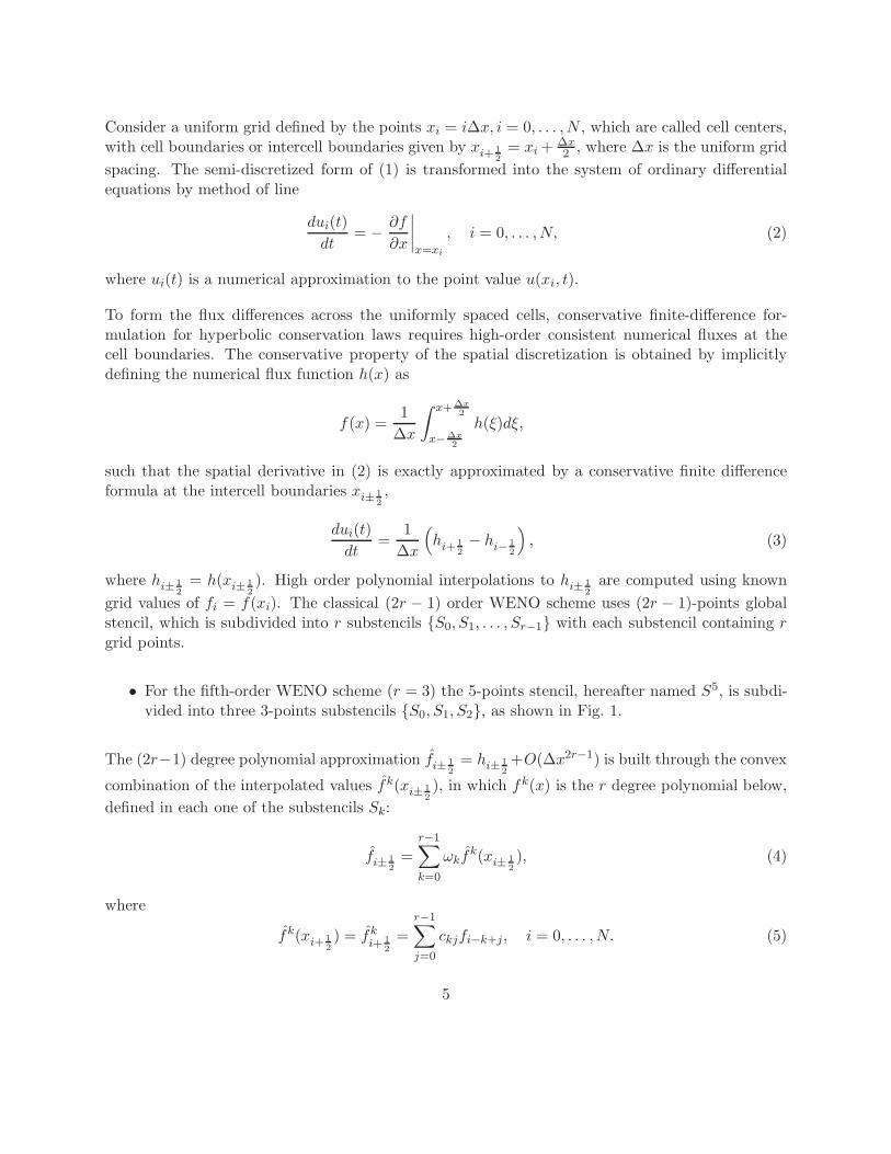
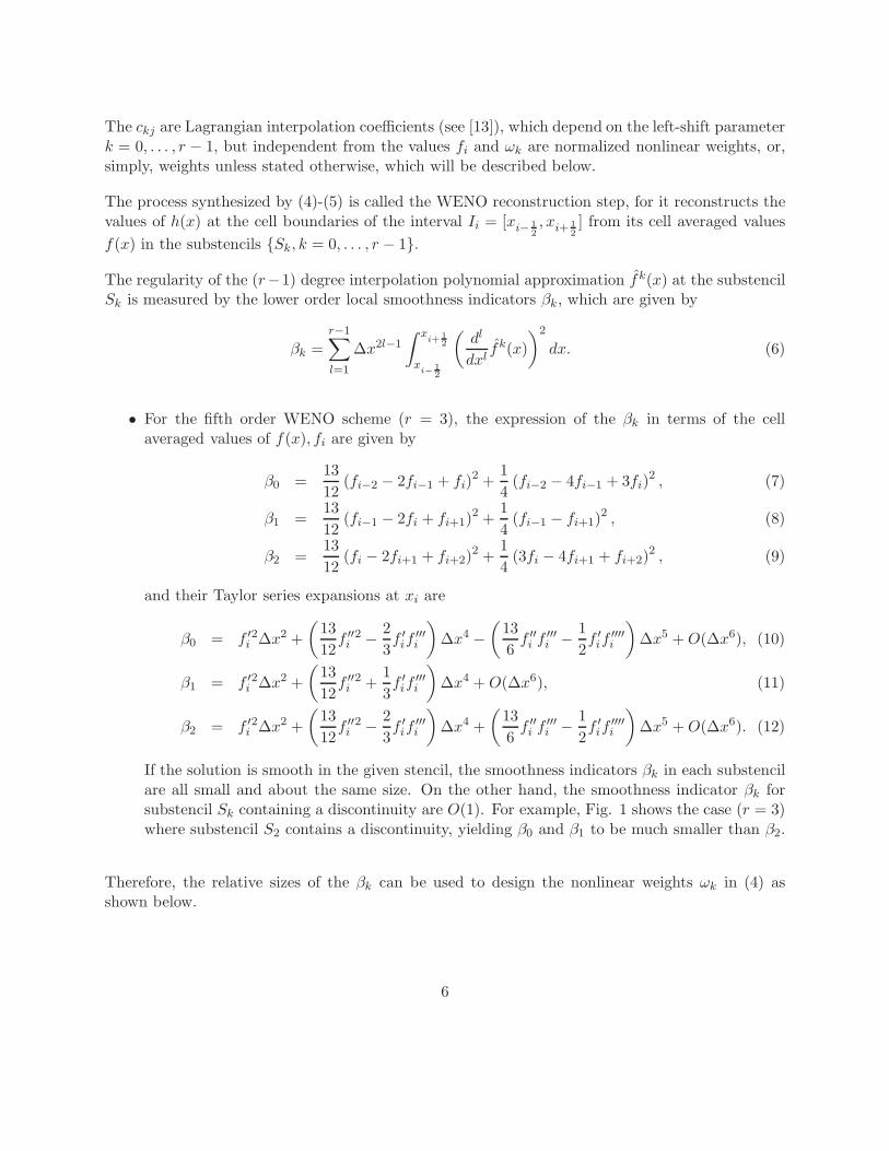
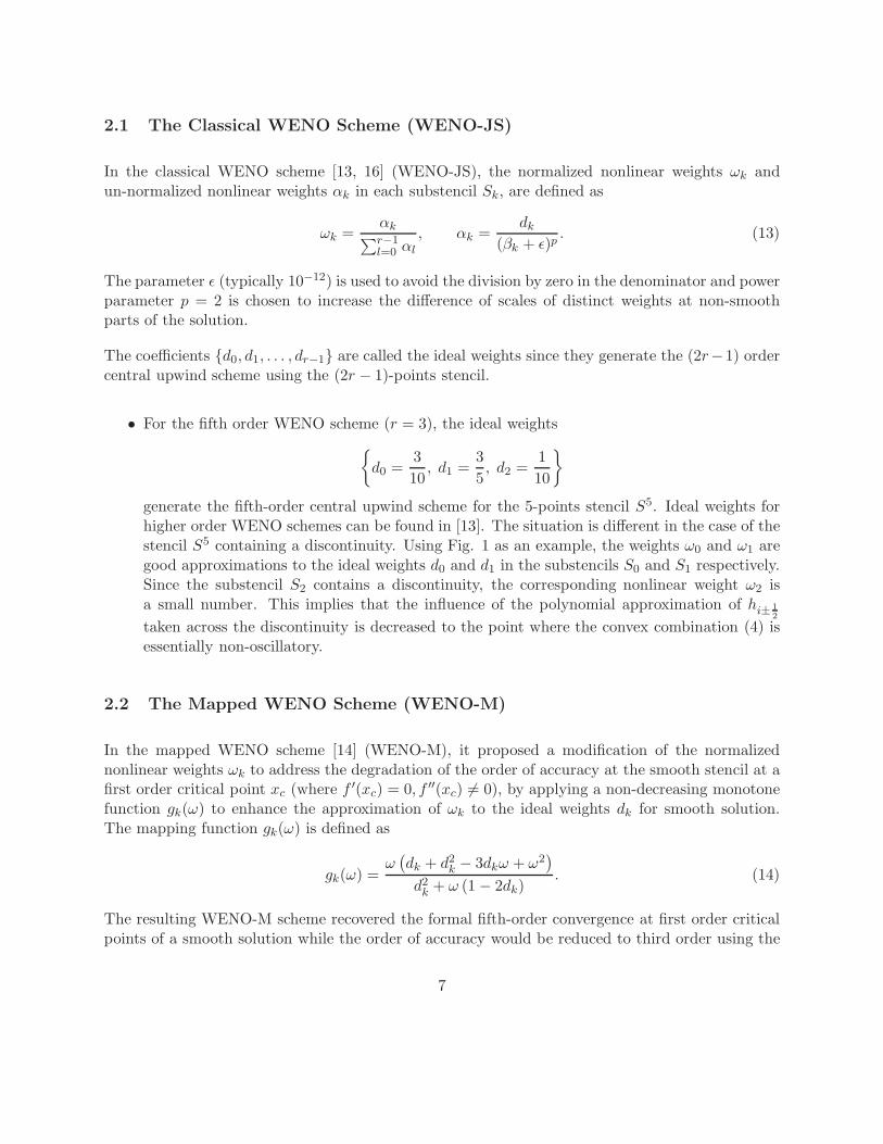
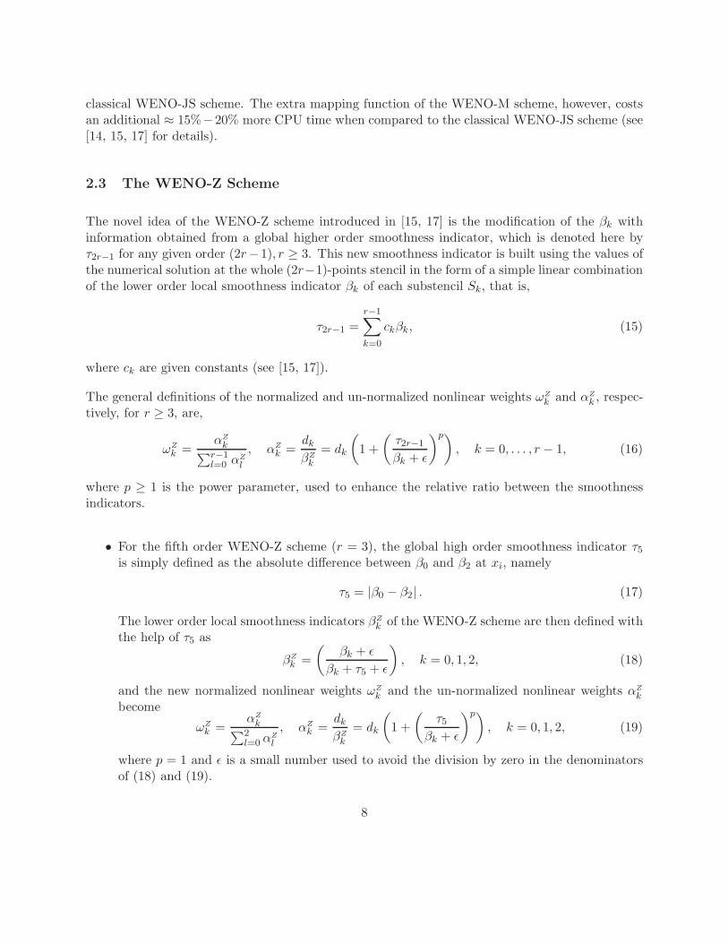
• For the fifth-order WENO scheme (r = 3) the 5-points stencil, hereafter named S5, is subdi-vided into three 3-points substencils {S0, S1, S2}, as shown in Fig. 1.
The (2r−1) degree polynomial approximation f̂i± 1
2
= hi± 1
2
+O(∆x2r−1) is built through the convex
combination of the interpolated values f̂k(xi± 12
), in which fk(x) is the r degree polynomial below,
defined in each one of the substencils Sk:
f̂i± 12
=
r−1∑
k=0
ωkf̂k(xi± 1
2
), (4)
where
f̂k(xi+ 12
) = f̂ki+ 1
2
=
r−1∑
j=0
ckjfi−k+j, i = 0, . . . ,N. (5)
5
The ckj are Lagrangian interpolation coefficients (see [13]), which depend on the left-shift parameterk = 0, . . . , r − 1, but independent from the values fi and ωk are normalized nonlinear weights, or,simply, weights unless stated otherwise, which will be described below.
The process synthesized by (4)-(5) is called the WENO reconstruction step, for it reconstructs thevalues of h(x) at the cell boundaries of the interval Ii = [xi− 1
2
, xi+ 12
] from its cell averaged values
f(x) in the substencils {Sk, k = 0, . . . , r − 1}.
The regularity of the (r−1) degree interpolation polynomial approximation f̂k(x) at the substencilSk is measured by the lower order local smoothness indicators βk, which are given by
βk =r−1∑
l=1
∆x2l−1
∫ xi+ 1
2
xi− 1
2
(
dl
dxlf̂k(x)
)2
dx. (6)
• For the fifth order WENO scheme (r = 3), the expression of the βk in terms of the cellaveraged values of f(x), fi are given by
β0 =13
12(fi−2 − 2fi−1 + fi)
2 +1
4(fi−2 − 4fi−1 + 3fi)
2 , (7)
β1 =13
12(fi−1 − 2fi + fi+1)
2 +1
4(fi−1 − fi+1)
2 , (8)
β2 =13
12(fi − 2fi+1 + fi+2)
2 +1
4(3fi − 4fi+1 + fi+2)
2 , (9)
and their Taylor series expansions at xi are
β0 = f ′i2∆x2 +
(
13
12f ′′
i2 −
2
3f ′
if′′′i
)
∆x4 −
(
13
6f ′′
i f ′′′i −
1
2f ′
if′′′′i
)
∆x5 + O(∆x6), (10)
β1 = f ′i2∆x2 +
(
13
12f ′′
i2 +
1
3f ′
if′′′i
)
∆x4 + O(∆x6), (11)
β2 = f ′i2∆x2 +
(
13
12f ′′
i2 −
2
3f ′
if′′′i
)
∆x4 +
(
13
6f ′′
i f ′′′i −
1
2f ′
if′′′′i
)
∆x5 + O(∆x6). (12)
If the solution is smooth in the given stencil, the smoothness indicators βk in each substencilare all small and about the same size. On the other hand, the smoothness indicator βk forsubstencil Sk containing a discontinuity are O(1). For example, Fig. 1 shows the case (r = 3)where substencil S2 contains a discontinuity, yielding β0 and β1 to be much smaller than β2.
Therefore, the relative sizes of the βk can be used to design the nonlinear weights ωk in (4) asshown below.
6
2.1 The Classical WENO Scheme (WENO-JS)
In the classical WENO scheme [13, 16] (WENO-JS), the normalized nonlinear weights ωk andun-normalized nonlinear weights αk in each substencil Sk, are defined as
ωk =αk
∑r−1l=0 αl
, αk =dk
(βk + ǫ)p. (13)
The parameter ǫ (typically 10−12) is used to avoid the division by zero in the denominator and powerparameter p = 2 is chosen to increase the difference of scales of distinct weights at non-smoothparts of the solution.
The coefficients {d0, d1, . . . , dr−1} are called the ideal weights since they generate the (2r−1) ordercentral upwind scheme using the (2r − 1)-points stencil.
• For the fifth order WENO scheme (r = 3), the ideal weights
{
d0 =3
10, d1 =
3
5, d2 =
1
10
}
generate the fifth-order central upwind scheme for the 5-points stencil S5. Ideal weights forhigher order WENO schemes can be found in [13]. The situation is different in the case of thestencil S5 containing a discontinuity. Using Fig. 1 as an example, the weights ω0 and ω1 aregood approximations to the ideal weights d0 and d1 in the substencils S0 and S1 respectively.Since the substencil S2 contains a discontinuity, the corresponding nonlinear weight ω2 isa small number. This implies that the influence of the polynomial approximation of hi± 1
2
taken across the discontinuity is decreased to the point where the convex combination (4) isessentially non-oscillatory.
2.2 The Mapped WENO Scheme (WENO-M)
In the mapped WENO scheme [14] (WENO-M), it proposed a modification of the normalizednonlinear weights ωk to address the degradation of the order of accuracy at the smooth stencil at afirst order critical point xc (where f ′(xc) = 0, f ′′(xc) 6= 0), by applying a non-decreasing monotonefunction gk(ω) to enhance the approximation of ωk to the ideal weights dk for smooth solution.The mapping function gk(ω) is defined as
gk(ω) =ω
(
dk + d2k − 3dkω + ω2
)
d2k + ω (1 − 2dk)
. (14)
The resulting WENO-M scheme recovered the formal fifth-order convergence at first order criticalpoints of a smooth solution while the order of accuracy would be reduced to third order using the
7
classical WENO-JS scheme. The extra mapping function of the WENO-M scheme, however, costsan additional ≈ 15%−20% more CPU time when compared to the classical WENO-JS scheme (see[14, 15, 17] for details).
2.3 The WENO-Z Scheme
The novel idea of the WENO-Z scheme introduced in [15, 17] is the modification of the βk withinformation obtained from a global higher order smoothness indicator, which is denoted here byτ2r−1 for any given order (2r−1), r ≥ 3. This new smoothness indicator is built using the values ofthe numerical solution at the whole (2r−1)-points stencil in the form of a simple linear combinationof the lower order local smoothness indicator βk of each substencil Sk, that is,
τ2r−1 =
r−1∑
k=0
ckβk, (15)
where ck are given constants (see [15, 17]).
The general definitions of the normalized and un-normalized nonlinear weights ωZk and αZ
k , respec-tively, for r ≥ 3, are,
ωZk =
αZk
∑r−1l=0 αZ
l
, αZk =
dk
βZk
= dk
(
1 +
(
τ2r−1
βk + ǫ
)p)
, k = 0, . . . , r − 1, (16)
where p ≥ 1 is the power parameter, used to enhance the relative ratio between the smoothnessindicators.
• For the fifth order WENO-Z scheme (r = 3), the global high order smoothness indicator τ5
is simply defined as the absolute difference between β0 and β2 at xi, namely
τ5 = |β0 − β2| . (17)
The lower order local smoothness indicators βZk of the WENO-Z scheme are then defined with
the help of τ5 as
βZk =
(
βk + ǫ
βk + τ5 + ǫ
)
, k = 0, 1, 2, (18)
and the new normalized nonlinear weights ωZk and the un-normalized nonlinear weights αZ
k
become
ωZk =
αZk
∑2l=0 αZ
l
, αZk =
dk
βZk
= dk
(
1 +
(
τ5
βk + ǫ
)p)
, k = 0, 1, 2, (19)
where p = 1 and ǫ is a small number used to avoid the division by zero in the denominatorsof (18) and (19).
8
The numerical results in [15] confirmed the usefulness of the new smoothness indicators (18) whichprovided high order convergent numerical solutions at critical points as WENO-M scheme with thesame computational cost as WENO-JS scheme. It has also been shown that the WENO-Z schemegenerates less dissipative solution than WENO-JS scheme at the same order of accuracy.
3 Governing Equations
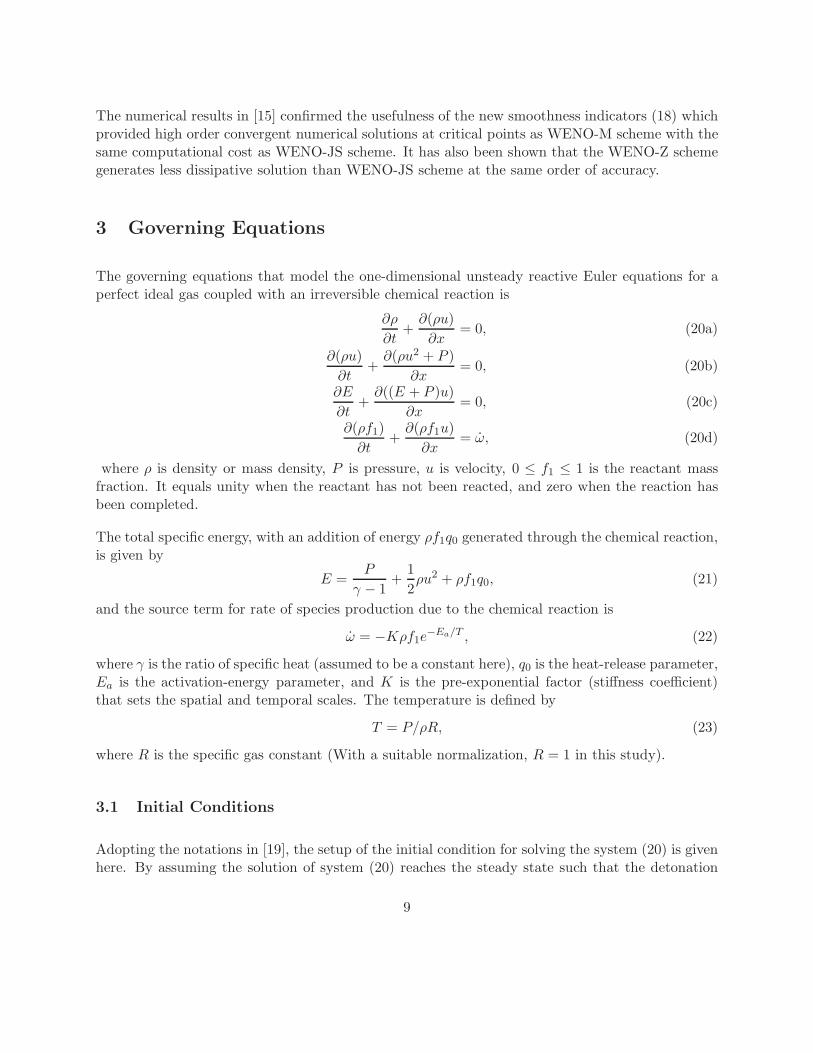
The governing equations that model the one-dimensional unsteady reactive Euler equations for aperfect ideal gas coupled with an irreversible chemical reaction is
∂ρ
∂t+
∂(ρu)
∂x= 0, (20a)
∂(ρu)
∂t+
∂(ρu2 + P )
∂x= 0, (20b)
∂E
∂t+
∂((E + P )u)
∂x= 0, (20c)
∂(ρf1)
∂t+
∂(ρf1u)
∂x= ω̇, (20d)
where ρ is density or mass density, P is pressure, u is velocity, 0 ≤ f1 ≤ 1 is the reactant massfraction. It equals unity when the reactant has not been reacted, and zero when the reaction hasbeen completed.
The total specific energy, with an addition of energy ρf1q0 generated through the chemical reaction,is given by
E =P
γ − 1+
1
2ρu2 + ρf1q0, (21)
and the source term for rate of species production due to the chemical reaction is
ω̇ = −Kρf1e−Ea/T , (22)
where γ is the ratio of specific heat (assumed to be a constant here), q0 is the heat-release parameter,Ea is the activation-energy parameter, and K is the pre-exponential factor (stiffness coefficient)that sets the spatial and temporal scales. The temperature is defined by
T = P/ρR, (23)
where R is the specific gas constant (With a suitable normalization, R = 1 in this study).
3.1 Initial Conditions
Adopting the notations in [19], the setup of the initial condition for solving the system (20) is givenhere. By assuming the solution of system (20) reaches the steady state such that the detonation
9
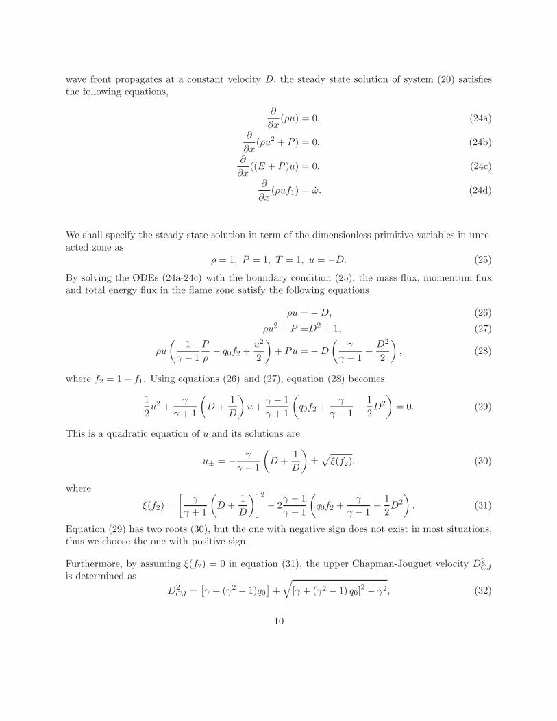
wave front propagates at a constant velocity D, the steady state solution of system (20) satisfiesthe following equations,
∂
∂x(ρu) = 0, (24a)
∂
∂x(ρu2 + P ) = 0, (24b)
∂
∂x((E + P )u) = 0, (24c)
∂
∂x(ρuf1) = ω̇. (24d)
We shall specify the steady state solution in term of the dimensionless primitive variables in unre-acted zone as
ρ = 1, P = 1, T = 1, u = −D. (25)
By solving the ODEs (24a-24c) with the boundary condition (25), the mass flux, momentum fluxand total energy flux in the flame zone satisfy the following equations
ρu = − D, (26)
ρu2 + P =D2 + 1, (27)
ρu
(
1
γ − 1
P
ρ− q0f2 +
u2
2
)
+ Pu = − D
(
γ
γ − 1+
D2
2
)
, (28)
where f2 = 1 − f1. Using equations (26) and (27), equation (28) becomes
1
2u2 +
γ
γ + 1
(
D +1
D
)
u +γ − 1
γ + 1
(
q0f2 +γ
γ − 1+
1
2D2
)
= 0. (29)
This is a quadratic equation of u and its solutions are
u± = −γ
γ − 1
(
D +1
D
)
±√
ξ(f2), (30)
where
ξ(f2) =
[
γ
γ + 1
(
D +1
D
)]2
− 2γ − 1
γ + 1
(
q0f2 +γ
γ − 1+
1
2D2
)
. (31)
Equation (29) has two roots (30), but the one with negative sign does not exist in most situations,thus we choose the one with positive sign.
Furthermore, by assuming ξ(f2) = 0 in equation (31), the upper Chapman-Jouguet velocity D2CJ
is determined as
D2CJ =
[
γ + (γ2 − 1)q0
]
+
√
[γ + (γ2 − 1) q0]2 − γ2, (32)
10
which is the minimum speed for ZND profile.
Hence, the detonation wave velocity D becomes
D2 = fD2CJ , (33)
where the non-dimensional parameter f ≥ 1 is the overdrive factor of detonation.
Giving the parameters γ and q0, the C-J velocity DCJ can be readily obtained by using equation(32). Then by specifying the overdrive factor f , the detonation velocity D can be determined.Finally, the primitive variables u, ρ and P for a given mass fraction f1 can be computed viaequations (26), (27) and (30). We refer to [19] for details.
In this study, the initial spatial profile of the mass fraction f1 is specified via an exponential function
f1(x) =
0, x ≤ x0 − L1/2,
exp
{
−α(
x0+2L1/2
4L1/2− x
)k}
, x0 + L1/2 > x > x0 − L1/2,
1, x ≥ x0 + L1/2,
(34)
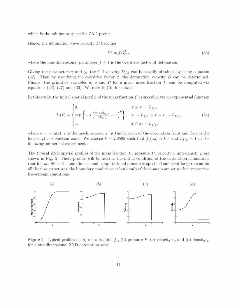
where α = − ln(ε), ε is the machine zero, x0 is the location of the detonation front and L1/2 is thehalf-length of reaction zone. We choose k = 2.8505 such that f1(x0) ≈ 0.5 and L1/2 = 1 in thefollowing numerical experiments.
The typical ZND spatial profiles of the mass fraction f1, pressure P , velocity u and density ρ areshown in Fig. 2. These profiles will be used as the initial condition of the detonation simulationsthat follow. Since the one-dimensional computational domain is specified sufficient large to containall the flow structures, the boundary conditions at both ends of the domain are set to their respectivefree-stream conditions.
(a) (b) (c) (d)
x
Mas
sF
ract
ion
0 1 2 3
0.2
0.4
0.6
0.8
1
x
Pre
ssur
e
0 1 2 30
20
40
60
80
x
Vel
ocity
0 1 2 3-10
-8
-6
-4
-2
0
x
Den
sity
0 1 2 30
2
4
6
8
10
Figure 2: Typical profiles of (a) mass fraction f1, (b) pressure P , (c) velocity u, and (d) density ρfor a one-dimensional ZND detonation wave.
11
3.2 Numerical Methods
We will employ the characteristics based WENO conservative finite difference scheme for system ofhyperbolic conservation laws (in this case, one-dimensional Euler equation). We approximate theinviscid flux, which is the classical Euler equations, via the well known (2r−1) order characteristic-based weighted essentially non-oscillatory conservative finite difference scheme (WENO) explicitly.Following [13, 15, 16], the hyperbolicity of the Euler equations admits a complete set of right andleft eigenvectors for the Jacobian of the system (see Appendix A for details). The approximatedeigenvalues and eigenvectors are obtained via the Roe linearized Riemann solver [18]. The first orderglobal Lax-Friedrichs flux is used as the low order building block for the high order reconstructionstep of the WENO scheme. After projecting the positive and negative fluxes on the characteristicfields via the left eigenvectors, the high order WENO reconstruction step is applied to obtain thehigh order approximation at the cell boundaries using the surrounding cell-centered values, whichare then projected back into the physical space via the right eigenvectors and added together to forma high order numerical flux at the cell-interfaces. The conservative difference of the reconstructedhigh order fluxes can then be computed for inviscid flux.
The resulting set of ODE (3) is advanced in time via the third order TVD Runge-Kutta scheme[13]. The CFL condition is set to be CFL = 0.4 in the numerical experiments performed in thisstudy. We refer to [13, 15] for further details on the WENO algorithm for solving the hyperbolicconservation laws.
4 Numerical Experiments and Discussion
According to the linear stability analysis [20, 21] of the conservation system (20), there is a largerange of the parameters γ, q0, Ea and f to make the detonation system unstable. In the numericalexperiments below, we use the following parameters
γ = 1.2, q0 = 50, Ea = 50. (35)
Therefore, the stability of detonation system is determined by the overdrive factor f only. Thelinear stability analysis shows that there is a critical value fc = 1.72 which determines the stabilityof the conservation system (20). The system is stable for the overdrive factor f ≥ fc and unstablefor f < fc [8].
In the following, we evaluate the performance of the three versions of WENO scheme on one stable(overdrive factor f = 1.8) and five unstable (overdrive factor f = 1.6, f = 1.4, f = 1.34, f = 1.3,f = 1.1) one-dimensional detonation waves, all of which have been studied with different numericaltechniques (most of them are low order schemes).
As the common practice, we define the resolution δn as the number of grid points in the half-reactionlength L1/2. The size of computation domain and the location of detonation front are calculated
12
approximately when the overdrive factor f and the final time tf are given. For instance, in thecase of overdrive factor f = 1.4 and final time tf = 100, the corresponding detonation velocity isD = 8.06 and detonation wave travels for distance about 806 unit-length (L1/2). Total number ofuniformly spaced grid points N must be greater than N ≥ 32240 with resolution δ40.
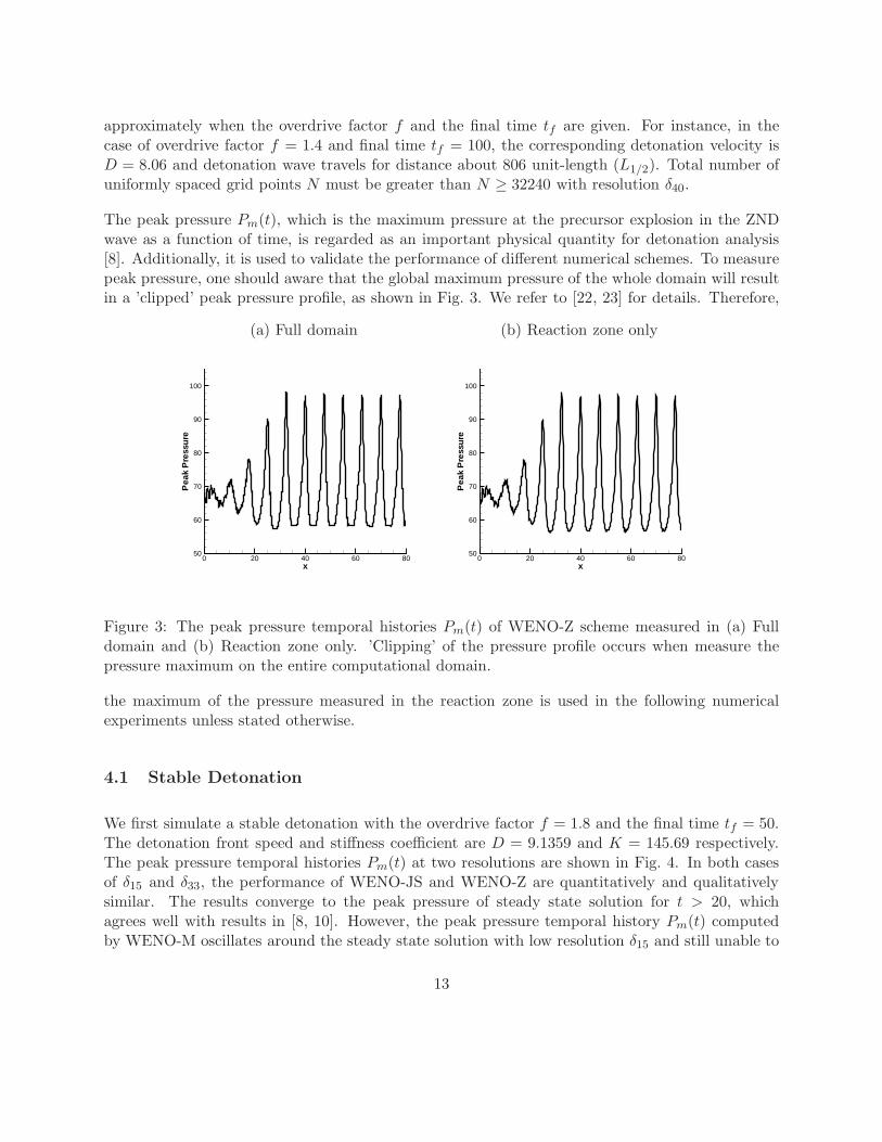
The peak pressure Pm(t), which is the maximum pressure at the precursor explosion in the ZNDwave as a function of time, is regarded as an important physical quantity for detonation analysis[8]. Additionally, it is used to validate the performance of different numerical schemes. To measurepeak pressure, one should aware that the global maximum pressure of the whole domain will resultin a ’clipped’ peak pressure profile, as shown in Fig. 3. We refer to [22, 23] for details. Therefore,
(a) Full domain (b) Reaction zone only
x
Pea
kP
ress
ure
0 20 40 60 8050
60
70
80
90
100
x
Pea
kP
ress
ure
0 20 40 60 8050
60
70
80
90
100
Figure 3: The peak pressure temporal histories Pm(t) of WENO-Z scheme measured in (a) Fulldomain and (b) Reaction zone only. ’Clipping’ of the pressure profile occurs when measure thepressure maximum on the entire computational domain.
the maximum of the pressure measured in the reaction zone is used in the following numericalexperiments unless stated otherwise.
4.1 Stable Detonation
We first simulate a stable detonation with the overdrive factor f = 1.8 and the final time tf = 50.The detonation front speed and stiffness coefficient are D = 9.1359 and K = 145.69 respectively.The peak pressure temporal histories Pm(t) at two resolutions are shown in Fig. 4. In both casesof δ15 and δ33, the performance of WENO-JS and WENO-Z are quantitatively and qualitativelysimilar. The results converge to the peak pressure of steady state solution for t > 20, whichagrees well with results in [8, 10]. However, the peak pressure temporal history Pm(t) computedby WENO-M oscillates around the steady state solution with low resolution δ15 and still unable to
13
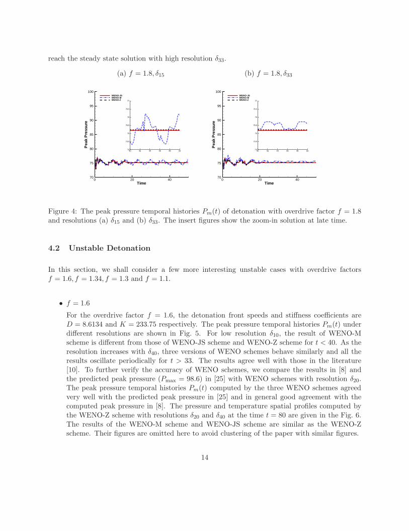
reach the steady state solution with high resolution δ33.
(a) f = 1.8, δ15 (b) f = 1.8, δ33
Time
Pea
kP
ress
ure
0 20 4070
75
80
85
90
95
100WENO-JSWENO-MWENO-Z
40 42 44 46 48 5074
74.5
75
75.5
76
76.5
77
40 42 44 46 48 5074
74.5
75
75.5
76
76.5
77
Time
Pea
kP
ress
ure
0 20 4070
75
80
85
90
95
100WENO-JSWENO-MWENO-Z
40 42 44 46 48 5074
74.5
75
75.5
76
76.5
77
40 42 44 46 48 5074
74.5
75
75.5
76
76.5
77
Figure 4: The peak pressure temporal histories Pm(t) of detonation with overdrive factor f = 1.8and resolutions (a) δ15 and (b) δ33. The insert figures show the zoom-in solution at late time.
4.2 Unstable Detonation
In this section, we shall consider a few more interesting unstable cases with overdrive factorsf = 1.6, f = 1.34, f = 1.3 and f = 1.1.
• f = 1.6
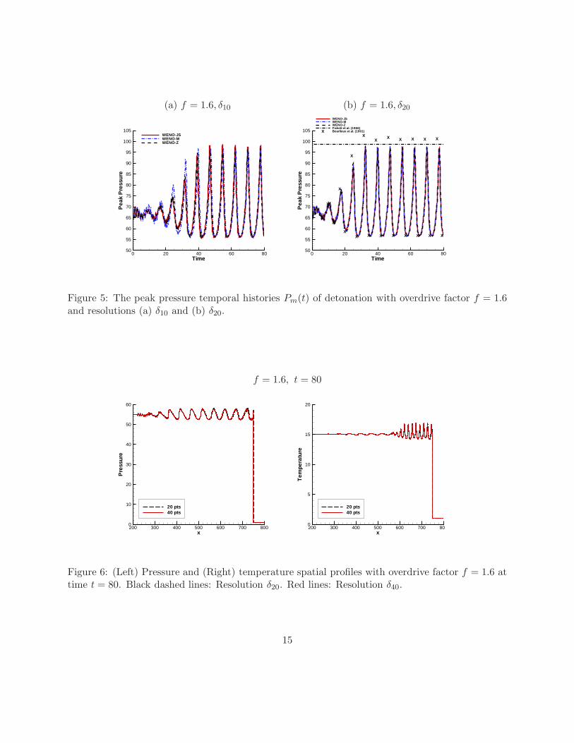
For the overdrive factor f = 1.6, the detonation front speeds and stiffness coefficients areD = 8.6134 and K = 233.75 respectively. The peak pressure temporal histories Pm(t) underdifferent resolutions are shown in Fig. 5. For low resolution δ10, the result of WENO-Mscheme is different from those of WENO-JS scheme and WENO-Z scheme for t < 40. As theresolution increases with δ40, three versions of WENO schemes behave similarly and all theresults oscillate periodically for t > 33. The results agree well with those in the literature[10]. To further verify the accuracy of WENO schemes, we compare the results in [8] andthe predicted peak pressure (Pmax = 98.6) in [25] with WENO schemes with resolution δ20.The peak pressure temporal histories Pm(t) computed by the three WENO schemes agreedvery well with the predicted peak pressure in [25] and in general good agreement with thecomputed peak pressure in [8]. The pressure and temperature spatial profiles computed bythe WENO-Z scheme with resolutions δ20 and δ40 at the time t = 80 are given in the Fig. 6.The results of the WENO-M scheme and WENO-JS scheme are similar as the WENO-Zscheme. Their figures are omitted here to avoid clustering of the paper with similar figures.
14
(a) f = 1.6, δ10 (b) f = 1.6, δ20
Time
Pea
kP
ress
ure
0 20 40 60 8050
55
60
65
70
75
80
85
90
95
100
105WENO-JSWENO-MWENO-Z
X
X
X
X
X
X
X
X
X
X
X
X
X
X
X
X
X
X
X
X
X
X
Time
Pea
kP
ress
ure
0 20 40 60 8050
55
60
65
70
75
80
85
90
95
100
105
WENO-JSWENO-MWENO-ZFickett et al. (1966)Bourlioux et al. (1991)X
Figure 5: The peak pressure temporal histories Pm(t) of detonation with overdrive factor f = 1.6and resolutions (a) δ10 and (b) δ20.
f = 1.6, t = 80
x
Pre
ssur
e
200 300 400 500 600 700 8000
10
20
30
40
50
60
20 pts40 pts
x
Tem
pera
ture
200 300 400 500 600 700 800
5
10
15
20
20 pts40 pts
Figure 6: (Left) Pressure and (Right) temperature spatial profiles with overdrive factor f = 1.6 attime t = 80. Black dashed lines: Resolution δ20. Red lines: Resolution δ40.
15
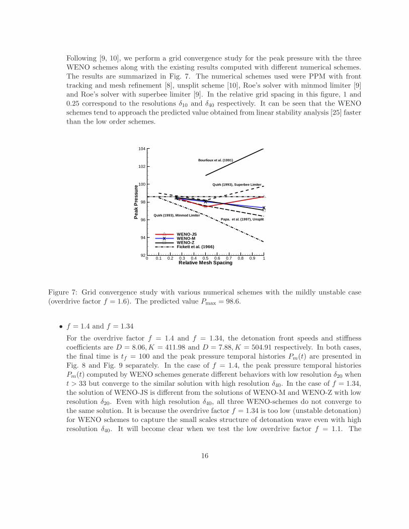
Following [9, 10], we perform a grid convergence study for the peak pressure with the threeWENO schemes along with the existing results computed with different numerical schemes.The results are summarized in Fig. 7. The numerical schemes used were PPM with fronttracking and mesh refinement [8], unsplit scheme [10], Roe’s solver with minmod limiter [9]and Roe’s solver with superbee limiter [9]. In the relative grid spacing in this figure, 1 and0.25 correspond to the resolutions δ10 and δ40 respectively. It can be seen that the WENOschemes tend to approach the predicted value obtained from linear stability analysis [25] fasterthan the low order schemes.
XX
X
Relative Mesh Spacing
Pea
kP
ress
ure
0 0.1 0.2 0.3 0.4 0.5 0.6 0.7 0.8 0.9 192
94
96
98
100
102
104
WENO-JSWENO-MWENO-ZFickett et al. (1966)
X
Bourlioux et al. (1991)
Quirk (1993), Superbee Limiter
Papa. et al. (1997), UnsplitQuirk (1993), Minmod Limiter
Figure 7: Grid convergence study with various numerical schemes with the mildly unstable case(overdrive factor f = 1.6). The predicted value Pmax = 98.6.
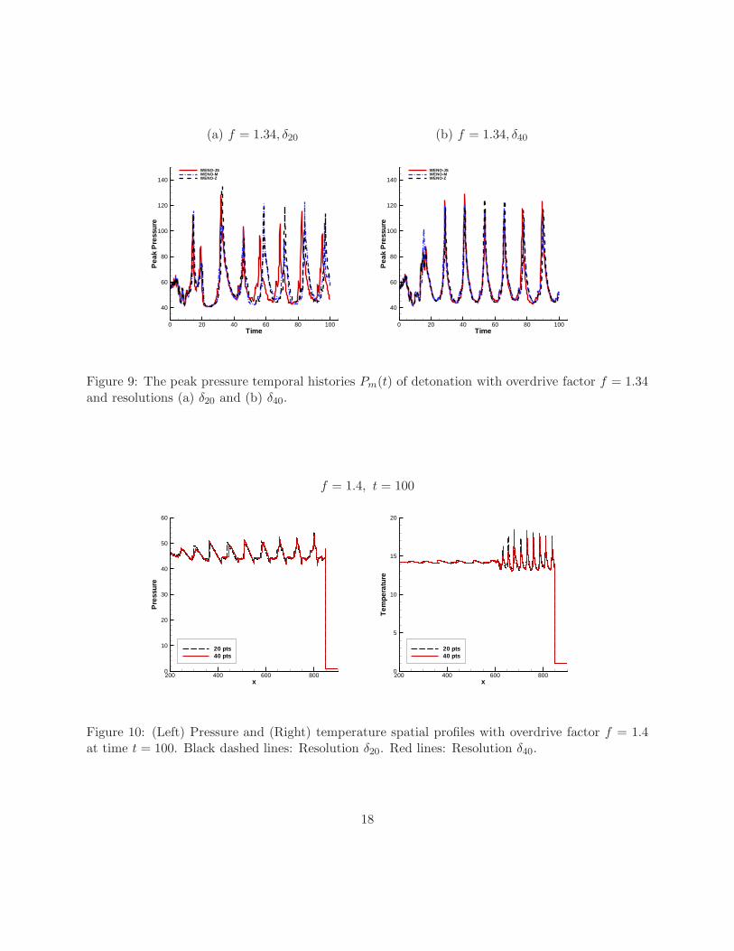
• f = 1.4 and f = 1.34
For the overdrive factor f = 1.4 and f = 1.34, the detonation front speeds and stiffnesscoefficients are D = 8.06,K = 411.98 and D = 7.88,K = 504.91 respectively. In both cases,the final time is tf = 100 and the peak pressure temporal histories Pm(t) are presented inFig. 8 and Fig. 9 separately. In the case of f = 1.4, the peak pressure temporal historiesPm(t) computed by WENO schemes generate different behaviors with low resolution δ20 whent > 33 but converge to the similar solution with high resolution δ40. In the case of f = 1.34,the solution of WENO-JS is different from the solutions of WENO-M and WENO-Z with lowresolution δ20. Even with high resolution δ40, all three WENO-schemes do not converge tothe same solution. It is because the overdrive factor f = 1.34 is too low (unstable detonation)for WENO schemes to capture the small scales structure of detonation wave even with highresolution δ40. It will become clear when we test the low overdrive factor f = 1.1. The
16
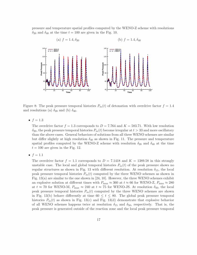
pressure and temperature spatial profiles computed by the WENO-Z scheme with resolutionsδ20 and δ40 at the time t = 100 are given in the Fig. 10.
(a) f = 1.4, δ20 (b) f = 1.4, δ40
Time
Pea
kP
ress
ure
0 20 40 60 80 10040
60
80
100
120
140WENO-JSWENO-MWENO-Z
Time
Pea
kP
ress
ure
0 20 40 60 80 10040
60
80
100
120
140WENO-JSWENO-MWENO-Z
Figure 8: The peak pressure temporal histories Pm(t) of detonation with overdrive factor f = 1.4and resolutions (a) δ20 and (b) δ40.
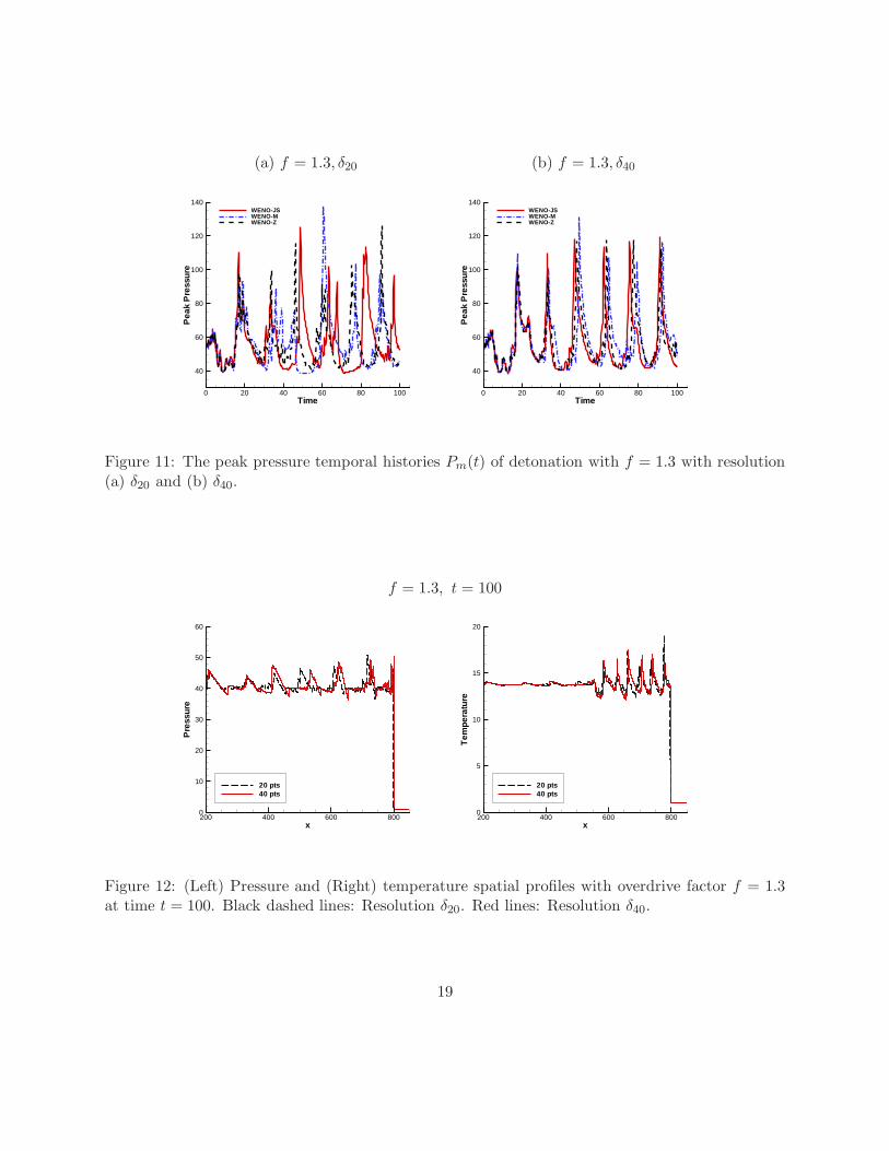
• f = 1.3
The overdrive factor f = 1.3 corresponds to D = 7.764 and K = 583.71. With low resolutionδ20, the peak pressure temporal histories Pm(t) become irregular at t > 33 and more oscillatorythan the above cases. General behaviors of solutions from all three WENO schemes are similarbut differ slightly at high resolution δ40 as shown in Fig. 11. The pressure and temperaturespatial profiles computed by the WENO-Z scheme with resolution δ20 and δ40 at the timet = 100 are given in the Fig. 12.
• f = 1.1
The overdrive factor f = 1.1 corresponds to D = 7.1418 and K = 1389.58 in this stronglyunstable case. The local and global temporal histories Pm(t) of the peak pressure shows noregular structures as shown in Fig. 13 with different resolution. At resolution δ15, the localpeak pressure temporal histories Pm(t) computed by the three WENO schemes as shown inFig. 13(a) are similar to the one shown in [24, 10]. However, the three WENO schemes exhibitan explosive solution at different times with Pmax ≈ 360 at t ≈ 66 for WENO-Z, Pmax ≈ 280at t ≈ 70 for WENO-M, Pmax ≈ 240 at t ≈ 75 for WENO-JS. At resolution δ50, the localpeak pressure temporal histories Pm(t) computed by the three WENO schemes are shownin Fig. 13(b) behave differently at time 60 ≤ t ≤ 80. The global peak pressure temporalhistories Pm(t) as shown in Fig. 13(c) and Fig. 13(d) demonstrate that explosive behaviorof all WENO schemes happens twice at resolution δ15 and δ50, respectively. That is, thepeak pressure is generated outside of the reaction zone and the local peak pressure temporal
17
(a) f = 1.34, δ20 (b) f = 1.34, δ40
Time
Pea
kP
ress
ure
0 20 40 60 80 100
40
60
80
100
120
140
WENO-JSWENO-MWENO-Z
Time
Pea
kP
ress
ure
0 20 40 60 80 100
40
60
80
100
120
140
WENO-JSWENO-MWENO-Z
Figure 9: The peak pressure temporal histories Pm(t) of detonation with overdrive factor f = 1.34and resolutions (a) δ20 and (b) δ40.
f = 1.4, t = 100
x
Pre
ssur
e
200 400 600 8000
10
20
30
40
50
60
20 pts40 pts
x
Tem
pera
ture
200 400 600 8000
5
10
15
20
20 pts40 pts
Figure 10: (Left) Pressure and (Right) temperature spatial profiles with overdrive factor f = 1.4at time t = 100. Black dashed lines: Resolution δ20. Red lines: Resolution δ40.
18
(a) f = 1.3, δ20 (b) f = 1.3, δ40
Time
Pea
kP
ress
ure
0 20 40 60 80 100
40
60
80
100
120
140WENO-JSWENO-MWENO-Z
Time
Pea
kP
ress
ure
0 20 40 60 80 100
40
60
80
100
120
140WENO-JSWENO-MWENO-Z
Figure 11: The peak pressure temporal histories Pm(t) of detonation with f = 1.3 with resolution(a) δ20 and (b) δ40.
f = 1.3, t = 100
x
Pre
ssur
e
200 400 600 8000
10
20
30
40
50
60
20 pts40 pts
x
Tem
pera
ture
200 400 600 8000
5
10
15
20
20 pts40 pts
Figure 12: (Left) Pressure and (Right) temperature spatial profiles with overdrive factor f = 1.3at time t = 100. Black dashed lines: Resolution δ20. Red lines: Resolution δ40.
19
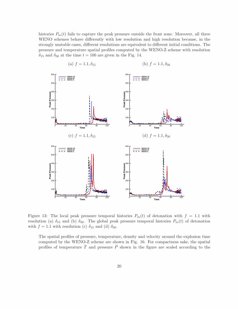
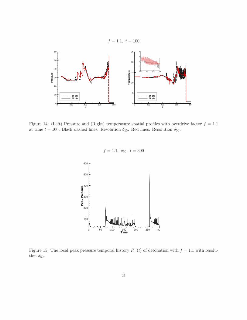
histories Pm(t) fails to capture the peak pressure outside the front zone. Moreover, all threeWENO schemes behave differently with low resolution and high resolution because, in thestrongly unstable cases, different resolutions are equivalent to different initial conditions. Thepressure and temperature spatial profiles computed by the WENO-Z scheme with resolutionδ15 and δ50 at the time t = 100 are given in the Fig. 14.
(a) f = 1.1, δ15 (b) f = 1.1, δ50
Time
Pea
kP
ress
ure
0 20 40 60 80 100
100
200
300
400
500
600WENO-JSWENO-MWENO-Z
TimeP
eak
Pre
ssur
e0 20 40 60 80 100
100
200
300
400
500
600WENO-JSWENO-MWENO-Z
(c) f = 1.1, δ15 (d) f = 1.1, δ50
Time
Pea
kP
ress
ure
0 20 40 60 80 100
100
200
300
400
500
600WENO-JSWENO-MWENO-Z
Time
Pea
kP
ress
ure
0 20 40 60 80 100
100
200
300
400
500
600WENO-JSWENO-MWENO-Z
Figure 13: The local peak pressure temporal histories Pm(t) of detonation with f = 1.1 withresolution (a) δ15 and (b) δ50. The global peak pressure temporal histories Pm(t) of detonationwith f = 1.1 with resolution (c) δ15 and (d) δ50.
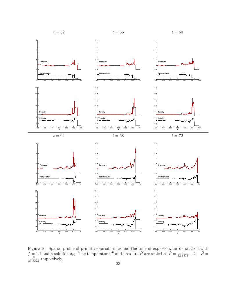
The spatial profiles of pressure, temperature, density and velocity around the explosion timecomputed by the WENO-Z scheme are shown in Fig. 16. For compactness sake, the spatialprofiles of temperature T̄ and pressure P̄ shown in the figure are scaled according to the
20
f = 1.1, t = 100
x
Pre
ssur
e
0 200 400 600 8000
10
20
30
40
50
60
15 pts50 pts
x
Tem
pera
ture
0 200 400 600 800
5
10
15
20
25
15 pts50 pts
610 620 630 64012
14
16
18
20
Figure 14: (Left) Pressure and (Right) temperature spatial profiles with overdrive factor f = 1.1at time t = 100. Black dashed lines: Resolution δ15. Red lines: Resolution δ50.
f = 1.1, δ50, t = 300
Time
Pea
kP
ress
ure
0 50 100 150 200 250 30
100
200
300
400
500
600
Figure 15: The local peak pressure temporal history Pm(t) of detonation with f = 1.1 with resolu-tion δ50.
21
following formulas
T̄ =T
12.8371− 2, P̄ =
P
33.8273.
To further show the behavior of the strongly unstable case, the representative local peakpressure temporal history Pm(t) of detonation computed by WENO-JS scheme is shown inthe Fig. 15. The relatively rapid explosion occurs again in the reaction zone at t ≈ 260. Thedetonation oscillates irregularly from t ≈ 90 to t ≈ 200 and then becomes relatively peacefulfrom t ≈ 20 to t ≈ 260.
Remark In [8, 10], it was proposed the existence of chaotic-pulsation instabilities because ofthe results sensitively depended on the initial data. Numerical experiments are performed witha perturbation on the ZND profiles of the fluid-dynamic variables with certain unity lengthfor lower value of overdrive factors f = 1.3 and f = 1.1. These initial small perturbationsaim at investigating the typical behaviors for chaotic system with small number of degree offreedom [8].
5 Conclusion and Future Work
In this work, we presented some preliminary numerical study of one dimensional detonation wavesimulations. The governing equations are a system of nonlinear hyperbolic conservation laws with aspecies production source term based on a simple irreversible chemical reaction. The heat generatedby the chemical reaction is added to the total energy of the system, which drives the detonationfront and vice versa. The behavior of the combustion front and the reaction zone right behind thefront depends exponentially on the local mass fraction and the temperature around the combustionfront. To solve the nonlinear hyperbolic system, we employed the high order weighted essentiallynonscillatory finite difference scheme and high order TVD Runge-Kutta scheme in order to capturesharp detonation fronts and to resolve small scales structures that appear in the highly complexsolution of PDEs. More specifically, the performance of three versions of fifth order characteristicbased WENO finite difference schemes, namely, the classical WENO scheme (WENO-JS), themapped WENO scheme (WENO-M) and the improved WENO scheme (WENO-Z) are studiedfor both the stable and unstable cases of detonation. The numerical code is written using thesubroutines in the high performance software library PseudoPack [26].
The stability of the system, for a given set of parameters, depends on the overdrive factor f . Weconducted numerical experiments with several overdrive factors f for both stable and unstabledetonation using the three WENO schemes at different grid resolutions. Both the temporal his-tory of the peak pressure and the spatial profiles of pressure and temperature at a given time arepresented for cases studied. For the stable detonation with overdrive factor f = 1.8, the computedpeak pressure in time reaches the theoretical steady state when computed by the WENO-JS andWENO-Z schemes. However, the WENO-M scheme failed to reach and oscillate around the theo-retical steady state even though the detonation is stable. It is indicative that the WENO-JS and
22
t = 52 t = 56 t = 60
x400 450 500 550 600 650 700
-2
0
2
4
6
Temperature
Pressure
x400 450 500 550 600 650 70
-2
0
2
4
6
Temperature
Pressure
x400 450 500 550 600 650 700
-2
0
2
4
6
Temperature
Pressure
x400 450 500 550 600 650 700
-5
0
5
10
15
20
25
Density
Velocity
x400 450 500 550 600 650 70
-5
0
5
10
15
20
25
Density
Velocity
x400 450 500 550 600 650 700
-5
0
5
10
15
20
25
Density
Velocity
t = 64 t = 68 t = 72
x400 450 500 550 600 650 70
-2
0
2
4
6
Temperature
Pressure
x400 450 500 550 600 650 700
-2
0
2
4
6
Temperature
Pressure
x400 450 500 550 600 650 70
-2
0
2
4
6
Temperature
Pressure
x400 450 500 550 600 650 70
-5
0
5
10
15
20
25
Density
Velocity
x400 450 500 550 600 650 700
-5
0
5
10
15
20
25
Density
Velocity
x400 450 500 550 600 650 70
-5
0
5
10
15
20
25
Density
Velocity
Figure 16: Spatial profile of primitive variables around the time of explosion, for detonation withf = 1.1 and resolution δ50. The temperature T̄ and pressure P̄ are scaled as T̄ = T
12.8371 − 2, P̄ =P
33.8273 respectively.23
WENO-Z schemes are a better choice than the WENO-M scheme for this class of problems. Forthe mildly unstable detonation with overdrive factors f = 1.6, 1.4 and f = 1.34, the peak pressureexhibits a steady and stable oscillatory behavior in time. The three WENO schemes agreed wellwith each others with an increased resolution. Moreover, the grid convergence study with overdrivefactor f = 1.6 shows that the high order WENO schemes converges to the predicted peak pressurefaster than the lower order schemes such as unsplit scheme, Roe’s solver with minmod limiter andRoe’s solver with superbee limiter. For strongly unstable detonation with overdrive factors f = 1.3and f = 1.1, the solutions of the system exhibit an increased chaotic behavior along with suddenstrong explosive growth of the peak pressure with similar results appeared in the literature. Thethree WENO schemes, due to the strongly unstable and sensitive nature of detonation on the tem-poral and spatial evolution of mass fraction and temperature at the earlier time, shows the time ofthe explosive behavior appear at slightly different times.
Also we examined the spatial profiles of the pressure and the temperature computed by the WENO-Z scheme at low and high resolutions. For the slightly unstable case with overdrive factor f = 1.6,solutions with both resolutions agreed well with each other. The solutions with increasingly unstablecases will become increasingly different. At the strongly unstable case with overdrive factor f = 1.1,the lower resolution solution is very different from the one computed with higher resolution.
In our future work in this area, we are interested in extending the methodology of high order nu-merical methods for simulating two and three dimensions problems in detonation with increasinglyrealistic chemical reactions and chemical species. For higher dimensional problems, we plan tointroduce a multi-modes perturbation and/or random perturbation within the reaction zone and tostudy the complex detonation behavior in such situations. We will examine quantitative behavior ofthe system via the mixing profile, statistics and spectra of perturbation energy fields (for example,see [27]).
Acknowledgments
The first author gratefully acknowledges the invitation of Prof. Wai-Sun Don and also extends hisgratitude to the Department of Mathematics at Hong Kong Baptist University for hosting his visit.He also acknowledges Prof. Cheng Wang for many useful discussions throughout the research.The authors (Li, Don) gratefully acknowledges the support of this research by Department ofMathematics at Hong Kong Baptist University. The author (Don) would like to thank the fundingsupport provided by the RGC grants HKBU-200910 and HKBU-200909 and the funding for author(Zhen) is partially supported by the RGC grant HKBU-200910 from Hong Kong Research GrantsCouncil.
24
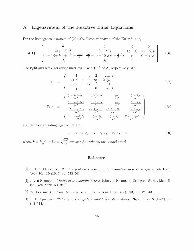
A Eigensystem of the Reactive Euler Equations
For the homogeneous system of (20), the Jacobian matrix of the Euler flux is,
A(Q) =
0 1 0 012 (γ − 3)u2 (3 − γ)u (γ − 1) (1 − γ)q0
(γ − 1)(q0f1u + u3) − γuEρ
γEρ − (γ − 1)(q0f1 + 3
2u2) γu (1 − γ)q0u
uf1 f1 0 u
. (36)
The right and left eigenvector matrices R and R−1 of A, respectively, are
R =
1 1 2 −2q0
u + c u − c 2u −2uq0
h + cu h − cu u2 0f1 f1 0 u2
, (37)
R−1 =
(γ−1)u2−2cu4c2 − (γ−1)u−c
2c2γ−12c2 − (γ−1)q0
2c2
(γ−1)u2+2cu4c2 − (γ−1)u+c
2c2γ−12c2 − (γ−1)q0
2c2
2c2−(γ−1)h2c2
(γ−1)h−c2
uc2c2−(γ−1)h
u2c2(γ−1)hq0
u2c2
− (γ−1)f1
2c2(γ−1)f1
uc2 − (γ−1)f1
u2c2(2h−u2)(γ−1)
2u2c2
, (38)
and the corresponding eigenvalues are,
λ1 = u + c, λ2 = u − c, λ3 = u, λ4 = u, (39)
where h = E+Pρ and c =
√
γPρ are specific enthalpy and sound speed.
References
[1] Y. B. Zeldovich, On the theory of the propagation of detonation in gaseous system, Zh. Eksp.Teor. Fiz. 10 (1940) pp. 542–568.
[2] J. von Neumann, Theory of Detonation Waves, John von Neumann, Collected Works, Macmil-lan, New York, 6 (1942).
[3] W. Doering, On detonation processes in gases, Ann. Phys. 43 (1943) pp. 421–436.
[4] J. J. Erpenbeck, Stability of steady-state equilibrium detonations, Phys. Fluids 5 (1962) pp.604–614.
25
[5] A. K. Oppenheim and R. I. Soloukhin, Experiments in gasdynamics of explosions, Ann. Rev.Fluid Mech. 5 (1973) pp. 31–58.
[6] W. Fickett and W. C. Davis, Detonation, University of California Press, Berkeley, (1979).
[7] J. H. S. Lee and I. O. Moen, The mechanism of transition from deflagration to detonation invapor cloud explosion, Progr. Energy Combust. Sci. 6 (1980) pp. 359–389.
[8] A. Bourlioux, A. J. Majda and V. Roytburd, Theoretical and Numerical Structure for UnstableOne-Dimensional Detonations, SIAM J. Appl. Math. 51 (1991) pp. 303–343.
[9] J. J. Quirk, Godunov-type schemes applied to detonation flows, ICASE Report 93 15 (1993).
[10] M. V. Papalexandris, A. Leonard and P. E. Dimotakis, Unsplit schemes for hyperbolic conser-vation laws with source terms in one space detonation, J. Comp. Phy. 134 (1997) pp. 31–61.
[11] A. K. Henrick, T. D. Aslam and J. M. Powers, Simulations of pulsating one-dimensionaldetonations with true fifth order accuracy, J. Comput. Phys. 213 (2006) 311–329.
[12] A. Harten, High resolution schemes for hyperbolic conservation laws, J. Comput. Phys. 49
(1983) pp. 357–393.
[13] G. S. Jiang and C. W. Shu, Efficient Implementation of Weighted ENO Schemes, J. Comp.Phys. 126 (1996) pp. 202–228.
[14] A. K. Henrick, T. D. Aslam and J. M. Powers, Mapped weighted essentially non-oscillatoryschemes: Achieving optimal order near critical points, J. Comp. Phys. 207 (2005) pp. 542–567.
[15] R. Borges, M. Carmona, B. Costa and W. S. Don, An improved weighted essentially non-oscillatory scheme for hyperbolic conservation laws, J. Comp. Phys. 227 (2008) pp. 3101–3211.
[16] D. Balsara and C. W. Shu, Monotonicity preserving weighted essentially non-oscillatoryschemes with increasingly high order of accuracy, J. Comp. Phys. 160 (2000) pp. 405–452.
[17] M. Castro, B. Costa and W. S. Don, High order weighted essentially non-oscillatory WENO-Zschemes for hyperbolic conservation laws, J. Comp. Phys. In press, (2010).
[18] E. F. Toro, Riemann solvers and numerical methods for fluid dynamics, A practical introduc-tion, Springer, 1999.
[19] Z. C. Zhang, S. T. Yu, H. He and S. C. Chang, Direct calculation of two- and three- dimensionaldetonations by an extended CE/SE method, AIAA (2001) pp. 2001–0476.
[20] J. J. Erpenbeck, Stability of idealized one-reaction detonations, Phys. Fluids 9 (1964) pp.684–696.
[21] H. I. Lee and D. S. Stewart, Calculation for linear detonation instability: one-dimensionalinstability of plane detonation, J. Fluid Mech. 206 (1990) pp. 103–132.
26
[22] P. Hwang, R. P. Fedkiw, B. Merriman, T. D. Aslam, A. R. Karagozian and S. J. Osher,Numerical resolution of pulsating detonation waves, Combust. Theor. Model. 4 (2000) pp.217–240.
[23] B. Engquist and B. Sjogren, Robust Difference Approximations of Stiff inviscid DetonationWaves, UCLA CAM Report (1991) pp. 91-03.
[24] L. T. He and J. H. S. Lee, The dynamical limit of one-dimensional detonations, Phys. Fluids7 (1995) pp. 1151–1158.
[25] W. Fickett and W. W. Wood, Flow calculation for pulsating one-dimensional detonation, Phys.Fluids 9 (1966) pp. 903–916.
[26] B. Costa and W. S. Don, PseudoPack 2001, http://www.cfm.brown.edu/people/wsdon/
[27] M. Latini, O. Schilling and W. S. Don, Effects of order of WENO flux reconstruction and spatialresolution on reshocked two-dimensional Richtmyer-Meshkov instability, J. Comp. Phys. 221
(2007) pp. 805–836.
27